- Table of Contents
-
- H3C SecPath M9000-X Multiservice Security Gateway Series Installation Guide-6W100
- 00-Preface
- 01-Chapter 1 Chassis views
- 02-Chapter 2 Preparing for Installation
- 03-Chapter 3 Installing the Gateway
- 04-Chapter 4 Accessing the Gateway and Configuring Basic Settings
- 05-Chapter 5 Troubleshooting
- 06-Chapter 6 Replacing Removable Components
- 07-Appendix A FRUs and Compatibility Matrixes
- 08-Appendix B Technical Specifications
- 09-Appendix C LEDs
- 10-Appendix D Cables
- 11-Appendix E Slot arrangement and interface numbering
- 12-Appendix F Engineering labels
- 13-Appendix G Cabling Recommendations
- 14-Appendix H Repackaging the Gateway
- Related Documents
-
| Title | Size | Download |
|---|---|---|
| 01-Chapter 1 Chassis views | 3.38 MB |
Chassis views
H3C SecPath M9000-X multiservice security gateways include the M9000-X06 and M9000-X10 models.
The main components of the gateway include supervisor engine modules (SEMs), interface switch modules, interface modules, service modules, switching fabric modules, fan trays, and power supplies. The gateway is not shipped with these components. Purchase them yourself as required.
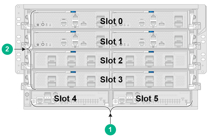
M9000-X06
Figure 1 Front view
|
(1) SEM section |
(2) Interface switch module section |
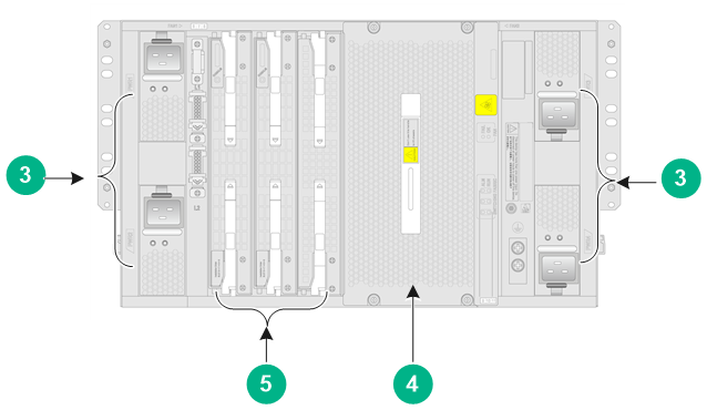
Figure 2 Rear view
|
(3) Power supply sections |
(4) Fan tray section |
|
(5) Switching fabric module section |
|
Table 1 Descriptions for the gateway sections
|
Section |
Description |
|
SEM section |
The SEMs are required. |
|
Interface switch module section |
The interface switch modules, service modules, and interface modules are required. An interface switch module provides two slots for the installation of service modules or interface modules. Do not hot swap interface modules or service modules. Install an interface module or service module on the slot of the interface switch module. |
|
Power supply section |
The power supplies are required. Determine the power supply model based on power distribution and the number of power supplies based on the system power consumption. |
|
Fan tray section |
The fan trays are required. |
|
Switching fabric module section |
The slot numbers of the switching fabric modules are located at the upper left corner and lower right corner of the switching fabric module section. Only slots 6 to 9 are available for installing switching fabric modules. Install a minimum of one switching fabric module if the device is installed with more than one interface switch module. If the device is installed with only one interface switch module, you can choose to not install any switching fabric modules. |
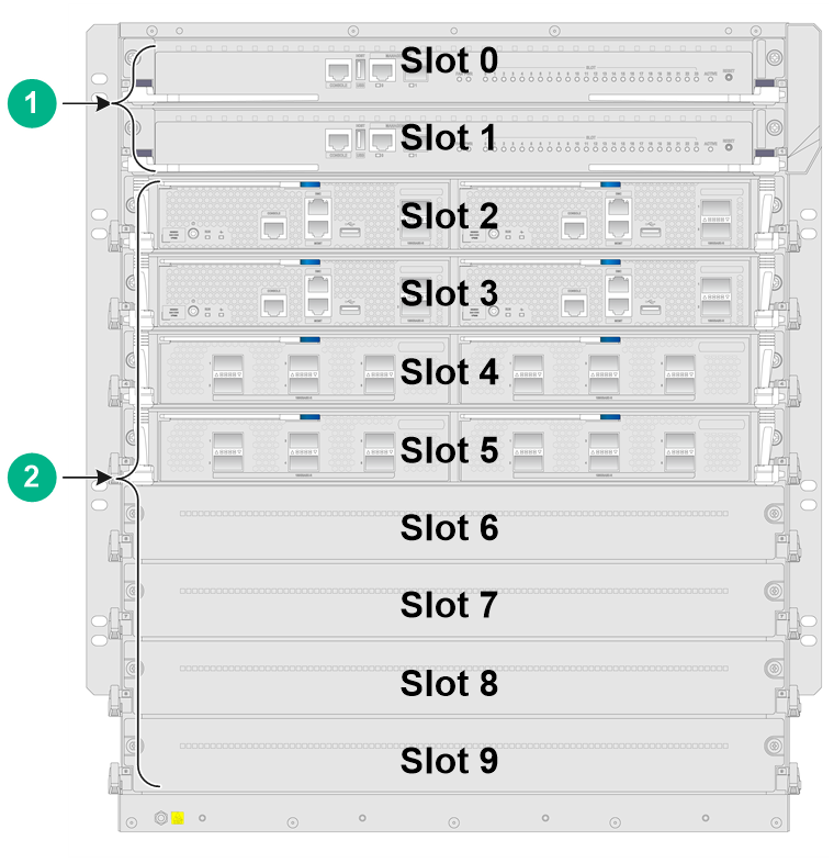
M9000-X10
Figure 3 Front view
|
(1) SEM section |
(2) Interface switch module section |
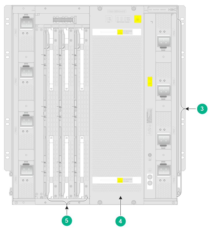
Figure 4 Rear view
|
(3) Power supply section |
(4) Fan tray section |
|
(5) Switching fabric module section |
|
Table 2 Descriptions for the gateway sections
|
Section |
Description |
|
SEM section |
The SEMs are required. |
|
Interface switch module section |
The interface switch modules, service modules, and interface modules are required. An interface switch module provides two slots for the installation of service modules or interface modules. Do not hot swap interface modules or service modules. Install an interface module or service module on the slot of the interface switch module. |
|
Power supply section |
The power supplies are required. Determine the power supply model based on power distribution and the number of power supplies based on the system power consumption. |
|
Fan tray section |
The fan trays are required. |
|
Switching fabric module section |
The switching fabric modules are required. You must install a minimum of one switching fabric module on the gateway. The slot numbers of the switching fabric modules are located at the upper left corner and lower right corner of the switching fabric module section. Only slots 10 to 13 are available for installing switching fabric modules. |
