- Table of Contents
-
- 11-Segment Routing Configuration Guide
- 00-Preface
- 01-SR-MPLS configuration
- 02-SR-MPLS TE policy configuration
- 03-SRv6 configuration
- 04-SRv6 TE policy configuration
- 05-SRv6 VPN overview
- 06-IP L3VPN over SRv6 configuration
- 07-EVPN L3VPN over SRv6 configuration
- 08-EVPN VPWS over SRv6 configuration
- 09-EVPN VPLS over SRv6 configuration
- 10-Public network IP over SRv6 configuration
- 11-SRv6 OAM configuration
- 12-SRv6 network slicing configuration
- Related Documents
-
| Title | Size | Download |
|---|---|---|
| 12-SRv6 network slicing configuration | 202.05 KB |
Configuring SRv6 network slicing
Network slice packet forwarding
Restrictions: Hardware compatibility with SRv6 network slicing
SRv6 network slicing tasks at a glance
Configuring the protocol number for IPv6 hop-by-hop extension headers
Configuring network slice channels on an interface
Configuring the NSI ID for an SRv6 TE policy candidate path
Configuring network slice packet statistics
Display and maintenance commands for SRv6 network slicing
SRv6 network slicing configuration examples
Example: Configuring SRv6 network slicing
Configuring SRv6 network slicing
About SRv6 network slicing
SRv6 network slicing divides an SRv6 network into multiple independent virtual networks. You can deploy different policies for different virtual networks based on their service types. Virtual networks are overlay networks. Multiple virtual networks can use the same underlay network.
Basic concepts
SRv6 network slicing has the following concepts:
· Network slice instance (NSI)—An independent virtual network in an SRv6 network with network slicing deployed. A virtual network is identified by its unique NSI ID. You can define the common attributes for a slice through the NSI. For example, you can configure the description for the slice.
· Network slice packet—An IPv6 packet transmitted in the NSI. The header of a network slice packet carries the NSI ID used for identifying the NSI to which the packet belongs.
· Network slice channel—A logical channel on an interface, used for forwarding network slice packets. A network slice channel is associated with an NSI by the NSI ID. You can create multiple network slice channels on an interface and assign an independent scheduling queue to each network slice channel. In this way, the scheduling queues for network slice channels do not affect each other.
Network slice packet format
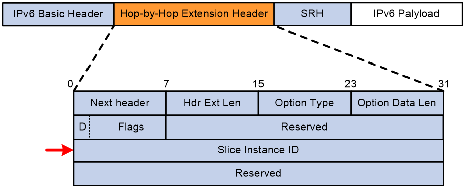
When forwarding a packet, an SRv6 source node adds an IPv6 hop-by-hop extension header to the packet. The IPv6 hop-by-hop extension header contains an NSI ID. As shown in Figure 1, an IPv6 hop-by-hop extension header contains the following key fields:
· Option Type—Option type. The value for this field is 0x1D, indicating that the option is an NSI ID option.
· Flags—This field is 8 bits long. The first bit of it is D flag (drop flag). The D flag determines how the device processes a packet that fails to match any network slice channel on the output interface.
¡ If the D flag is set to 0, the device ignores the NSI ID in the packet and forwards the packet out of the output interface.
¡ If the D flag is set to 1, the device cannot ignore the NSI ID in the packet. The packet is dropped.
· Slice Instance ID—ID of the NSI to which the packet belongs. This field is 32 bits long.
Figure 1 IPv6 hop-by-hop extension header that contains an NSI ID
Network slice packet forwarding
The NSI ID is a key identifier for SRv6 network slicing. A network slice packet always carries an NSI ID. You must associate an SRv6 TE policy with an NSI ID as follows:
· Manually specify the NSI ID for the SRv6 TE policy.
· The device learns the NSI ID from the BGP IPv6 SR policy route advertised by the peer.
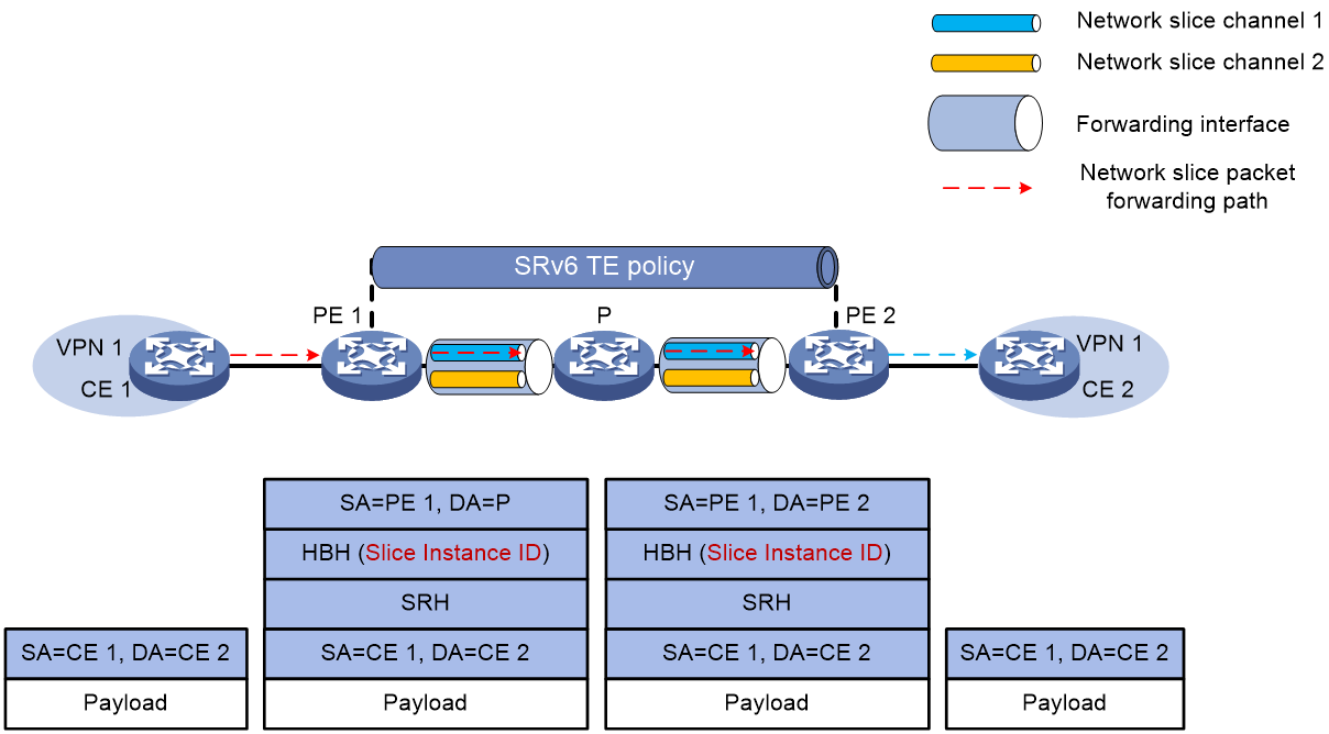
The following describes how SRv6 network slice packets are forwarded in an L3VPNv4 over SRv6 TE network.
The SRv6 network contains NSI 1 and NSI 2. The interfaces on PE 1, P, and PE 2 contain network slice channel 1 and network slice channel 2 that correspond to NSI 1 and NSI 2, respectively. In VPN 1, an SRv6 TE policy carries traffic between CE 1 and CE 2, and is associated with NSI 1. A packet from CE 1 to CE 2 is forwarded as follows:
1. CE 1 sends an IPv4 unicast packet to PE 1. After receiving the packet from CE 1, PE 1 looks up the VPN instance routing table, and finds the route that uses an SRv6 TE policy as the output interface. PE 1 encapsulates the following information into the packet:
¡ The SRH header that carries the SID list of the SRv6 TE policy.
¡ The HBH extension header that carries the NSI ID associated with the SRv6 TE policy. The NSI ID is 1.
¡ IPv6 basic header.
2. PE 1 forwards the packet to P through the network slice channel that matches the NSI ID.
3. P forwards the packet based on the SRH header through the network slice channel that matches the NSI ID.
4. After receiving the packet, PE 2 looks up the local SID list based on the destination IPv6 address of the packet, and finds the End SID. PE 2 reduces the SL of the packet by 1, and updates the destination IPv6 address to the End.DT4 SID. PE 2 looks up the local SID list, and performs the forwarding action corresponding to the End.DT4 SID. PE 2 decapsulates the IPv6 header, and finds VPN 1 that matches the End.DT4 SID. It then looks up the routing table of VPN 1, and forwards the packet to CE 2.
Figure 2 SRv6 network slice packet forwarding
Restrictions: Hardware compatibility with SRv6 network slicing
This feature is available only for the following cards:
|
Card category |
Cards |
|
CEPC |
CEPC-CQ8L, CEPC-CQ8LA, CEPC-CQ8L1A, CEPC-CQ16L1 |
|
CSPEX |
CSPEX-1802X, CSPEX-1802XA, CSPEX-2612XA, CSPEX-1812X-E, CSPEX-2304X-G, CSPEX-1502XA |
|
SPE |
RX-SPE200-E |
SRv6 network slicing tasks at a glance
To configure SRv6 network slicing, perform the following tasks:
1. Create an SRv6 TE policy and configure its basic attributes
Perform this task on the source node of the SRv6 network. For more information, see "Configuring SRv6 TE policies."
2. Configure traffic steering to the SRv6 TE policy
For more information, see "Configuring SRv6 TE policies."
3. Create SRv6 NSIs and configure their basic attributes
b. Configuring the protocol number for IPv6 hop-by-hop extension headers
4. Configuring network slice channels on an interface
5. Configuring the NSI ID for an SRv6 TE policy candidate path
6. (Optional.) Configuring network slice packet statistics
Configuring an SRv6 NSI
Restrictions and guidelines
To delete an NSI associated with an interface, first remove the association.
Procedure
1. Enter system view.
system-view
2. Enable network slicing and enter network slice view.
network-slice
By default, network slicing is disabled.
3. Create an NSI and enter its view.
instance slice-instance-id
4. (Optional.) Configure the description for the NSI.
description text
By default, no description is configured for an NSI.
Configuring the protocol number for IPv6 hop-by-hop extension headers
About this task
With SRv6 network slicing enabled, an SRv6 source node adds an IPv6 hop-by-hop extension header to a packet. The IPv6 hop-by-hop extension header contains an NSI ID. By default, the protocol number in an IPv6 hop-by-hop extension header is 0, indicating that the Next Header field of the preceding IPv6 header is 0. Upon receiving a packet, a network slicing incapable device cannot parse the IPv6 hop-by-hop extension header with protocol number 0. As a result, the packet processing becomes slow or the packet is dropped. To avoid such issues, you can use this feature to set the protocol number to a value other than 0. After that, the network slicing incapable device ignores the IPv6 hop-by-hop extension header with protocol number 0, and forwards the packet based on its IPv6 basic header. The protocol number of IPv6 hop-by-hop extension headers varies by vendor. You can edit the protocol number for interoperability between devices from different vendors.
Procedure
1. Enter system view.
system-view
2. Enter network slice view.
network-slice
3. Set the protocol number for IPv6 hop-by-hop extension headers.
protocol-number number
The default protocol number of IPv6 hop-by-hop extension headers is 0.
Configuring network slice channels on an interface
About this task
With network slicing enabled for an interface, you can create network slice channels on the interface. The device assigns an independent scheduling queue to each network slice channel identified by an NIS ID. Packets matching an NSI ID will be forwarded through the associated channel. The protocol number of the IPv6 hop-by-hop extension headers of packets is the protocol number specified for the NSI ID associated with the channel.
Restrictions and guidelines
Before you enable network slicing, use the instance command to create NSIs.
You can configure multiple network slice channels on an interface.
Only the following interfaces support this feature:
· Layer 3 Ethernet interfaces.
· Layer 3 Ethernet subinterfaces.
· Layer 3 aggregate interfaces.
· Layer 3 aggregate subinterfaces.
· FlexE logical interfaces.
· FlexE logical subinterfaces.
You can enable this feature for a Layer 3 aggregate interface or its subinterface only when all member interfaces of that Layer 3 aggregate interface are on the following cards:
|
Card category |
Cards |
|
CEPC |
CEPC-CQ8L, CEPC-CQ8LA, CEPC-CQ8L1A, CEPC-CQ16L1 |
|
CSPEX |
CSPEX-1802X, CSPEX-1802XA, CSPEX-2612XA, CSPEX-1812X-E, CSPEX-2304X-G, CSPEX-1502XA |
|
SPE |
RX-SPE200-E |
After enabling this feature, you cannot add physical interfaces on a card that does not support this feature to the Layer 3 aggregate interface.
Procedure
1. Enter system view.
system-view
2. Enter interface view.
interface interface-type interface-number
3. Enable network slicing for the interface and enter network slice view of the interface.
network-slice enable
By default, network slicing is disabled for an interface.
4. Configure a network slice channel on the interface and specify the channel bandwidth.
slice-id slice-instance-id flex-channel flex-channel-value
By default, no network slice channels are configured on an interface.
Configuring the NSI ID for an SRv6 TE policy candidate path
About this task
You can specify an NSI ID for an SRv6 TE policy candidate path. If the path is selected, the device encapsulates an IPv6 hop-by-hop extension header that contains the NSI ID into packets forwarded through the path. If an output interface on the path contains a network slice channel that matches the NSI ID, the packets are forwarded through the channel.
Procedure
1. Enter system view.
system-view
2. Enter SRv6 view.
segment-routing ipv6
3. Enter SRv6 TE view.
traffic-engineering
4. Enter SRv6 TE policy view.
policy policy-name
5. Create and enter SRv6 TE policy candidate path view.
candidate-paths
6. Set the preference for a candidate path and enter SRv6 TE policy path preference view.
preference preference-value
Each preference represents a candidate path.
7. Specify an NSI ID for the SRv6 TE policy candidate path.
network-slice slice-instance-id
By default, no NSI ID is specified for an SRv6 TE policy candidate path.
Configuring network slice packet statistics
About this task
With network slice packet statistics enabled, you can use the display network-slice statistics command to view network slice packet statistics.
Procedure
1. Enter system view.
system-view
2. Enter network slice view.
network-slice
3. Enable network slice packet statistics.
statistics enable
By default, network slice packet statistics is disabled.
4. (Optional.) Set the interval for collecting network slice packet statistics.
statistics interval time
By default, the device collects network slice packet statistics at 30-second intervals.
Display and maintenance commands for SRv6 network slicing
Execute display commands in any view and reset commands in user view.
|
Task |
Command |
|
Display associations between NSIs and interfaces. |
display network-slice binding-list [ slice-id slice-instance-id ] [ interface interface-type interface-number ] |
|
Display network slicing configuration. |
display network-slice configuration |
|
Display network slice packet statistics. |
display network-slice statistics [ slice-id slice-instance-id ] [ interface interface-type interface-number ] [ verbose ] |
|
Clear network slice packet statistics. |
reset network-slice statistics [ slice-id slice-instance-id ] [ interface interface-type interface-number ] |
SRv6 network slicing configuration examples
Example: Configuring SRv6 network slicing
Network configuration
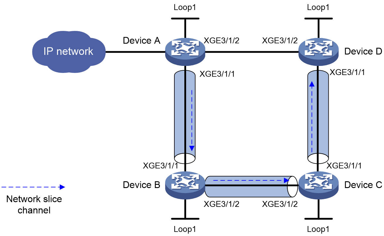
As shown in Figure 3, perform the following tasks on the devices to forward user packets through the network slice on Device A, Device B, Device C, and Device D:
· Configure Device A through Device D to run IS-IS to implement Layer 3 connectivity.
· Deploy an NSI on Device A through Device D. Configure a network slice channel on the output interfaces of Device A through Device D.
· Configure an SRv6 TE policy associated with the NSI to forward user packets along path Device A > Device B > Device C > Device D
|
Device |
Interface |
IP address |
Device |
Interface |
IP address |
|
Device A |
Loop1 |
1::1/128 |
Device B |
Loop1 |
2::2/128 |
|
|
XGE3/1/1 |
1000::1/64 |
|
XGE3/1/1 |
1000::2/64 |
|
|
XGE3/1/2 |
4000::1/64 |
|
XGE3/1/2 |
2000::2/64 |
|
Device C |
Loop1 |
3::3/128 |
Device D |
Loop1 |
4::4/128 |
|
|
XGE3/1/1 |
3000::3/64 |
|
XGE3/1/1 |
3000::4/64 |
|
|
XGE3/1/2 |
2000::3/64 |
|
XGE3/1/2 |
4000::4/64 |
Procedure
1. Configure IPv6 addresses and prefix lengths for the interfaces. (Details not shown.)
2. Configure Device A:
# Create NSI 1, specify the protocol number for the IPv6 hop-by-hop extension header, and enable network slice packet statistics.
<DeviceA> system-view
[DeviceA] network-slice
[DeviceA-network-slice] protocol-number 160
[DeviceA-network-slice] statistics enable
[DeviceA-network-slice] instance 1
[DeviceA-network-slice-instance-1] quit
# Configure a network slice channel on the interface.
[DeviceA] interface ten-gigabitethernet 3/1/1
[DeviceA-Ten-GigabitEthernet3/1/1] network-slice enable
[DeviceA-Ten-GigabitEthernet3/1/1-network-slice] slice-id 1 flex-channel 100
[DeviceA-Ten-GigabitEthernet3/1/1-network-slice] quit
[DeviceA-Ten-GigabitEthernet3/1/1] quit
# Specify the source address in the IPv6 header that the SRv6 VPN encapsulates into the IPv6 packets.
[DeviceA] segment-routing ipv6
[DeviceA-segment-routing-ipv6] encapsulation source-address 1::1
# Configure a locator and configure SRv6 End SIDs.
[DeviceA-segment-routing-ipv6] locator a ipv6-prefix 5000:: 64 static 32
[DeviceA-segment-routing-ipv6-locator-a] opcode 1 end no-flavor
[DeviceA-segment-routing-ipv6-locator-a] quit
# Specify a locator for the BSID of the SRv6 TE policy.
[DeviceA-segment-routing-ipv6] traffic-engineering
[DeviceA-srv6-te] srv6-policy locator a
# Configure an SID list.
[DeviceA-srv6-te] segment-list s1
[DeviceA-srv6-te-sl-s1] index 10 ipv6 6000::1
[DeviceA-srv6-te-sl-s1] index 20 ipv6 7000::1
[DeviceA-srv6-te-sl-s1] index 30 ipv6 8000::1
[DeviceA-srv6-te-sl-s1] quit
# Create SRv6 TE policy p1 and configure its attributes. Associate NSI 1 with SRv6 TE policy p1.
[DeviceA-srv6-te] policy p1
[DeviceA-srv6-te-policy-p1] binding-sid ipv6 5000::2
[DeviceA-srv6-te-policy-p1] color 10 end-point ipv6 4::4
[DeviceA-srv6-te-policy-p1] candidate-paths
[DeviceA-srv6-te-policy-p1-path] preference 10
[DeviceA-srv6-te-policy-p1-path-pref-10] network-slice 1
[DeviceA-srv6-te-policy-p1-path-pref-10] explicit segment-list s1
[DeviceA-srv6-te-policy-p1-path-pref-10] quit
[DeviceA-srv6-te-policy-p1-path] quit
[DeviceA-srv6-te-policy-p1] quit
[DeviceA-srv6-te] quit
[DeviceA-segment-routing-ipv6] quit
# Configure IS-IS and set the IS-IS cost style to wide.
[DeviceA] isis 1
[DeviceA-isis-1] network-entity 00.0000.0000.0001.00
[DeviceA-isis-1] cost-style wide
[DeviceA-isis-1] address-family ipv6 unicast
[DeviceA-isis-1-ipv6] segment-routing ipv6 locator a
[DeviceA-isis-1-ipv6] quit
[DeviceA-isis-1] quit
[DeviceA] interface ten-gigabitethernet 3/1/1
[DeviceA-Ten-GigabitEthernet3/1/1] isis ipv6 enable 1
[DeviceA-Ten-GigabitEthernet3/1/1] quit
[DeviceA] interface ten-gigabitethernet 3/1/2
[DeviceA-Ten-GigabitEthernet3/1/2] isis ipv6 enable 1
[DeviceA-Ten-GigabitEthernet3/1/2] quit
[DeviceA] interface loopback 1
[DeviceA-LoopBack1] isis ipv6 enable 1
[DeviceA-LoopBack1] quit
3. Configure Device B.
# Create NSI 1, specify the protocol number for the IPv6 hop-by-hop extension header, and enable network slice packet statistics.
<DeviceB> system-view
[DeviceB] network-slice
[DeviceB-network-slice] protocol-number 160
[DeviceB-network-slice] statistics enable
[DeviceB-network-slice] instance 1
[DeviceB-network-slice-instance-1] quit
# Configure a network slice channel on the interfaces.
[DeviceB] interface ten-gigabitethernet 3/1/1
[DeviceB-Ten-GigabitEthernet3/1/1] network-slice enable
[DeviceB-Ten-GigabitEthernet3/1/1-network-slice] slice-id 1 flex-channel 100
[DeviceB-Ten-GigabitEthernet3/1/1-network-slice] quit
[DeviceB-Ten-GigabitEthernet3/1/1] quit
[DeviceB] interface ten-gigabitethernet 3/1/2
[DeviceB-Ten-GigabitEthernet3/1/2] network-slice enable
[DeviceB-Ten-GigabitEthernet3/1/2-network-slice] slice-id 1 flex-channel 100
[DeviceB-Ten-GigabitEthernet3/1/2-network-slice] quit
[DeviceB-Ten-GigabitEthernet3/1/2] quit
# Specify the SRv6 End SID.
[DeviceB] segment-routing ipv6
[DeviceB-segment-routing-ipv6] locator b ipv6-prefix 6000:: 64 static 32
[DeviceB-segment-routing-ipv6-locator-b] opcode 1 end no-flavor
[DeviceB-segment-routing-ipv6-locator-b] quit
[DeviceB-segment-routing-ipv6] quit
# Configure IS-IS and set the IS-IS cost style to wide.
[DeviceB] isis 1
[DeviceB-isis-1] network-entity 00.0000.0000.0002.00
[DeviceB-isis-1] cost-style wide
[DeviceB-isis-1] address-family ipv6 unicast
[DeviceB-isis-1-ipv6] segment-routing ipv6 locator b
[DeviceB-isis-1-ipv6] quit
[DeviceB-isis-1] quit
[DeviceB] interface ten-gigabitethernet 3/1/1
[DeviceB-Ten-GigabitEthernet3/1/1] isis ipv6 enable 1
[DeviceB-Ten-GigabitEthernet3/1/1] quit
[DeviceB] interface ten-gigabitethernet 3/1/2
[DeviceB-Ten-GigabitEthernet3/1/2] isis ipv6 enable 1
[DeviceB-Ten-GigabitEthernet3/1/2] quit
[DeviceB] interface loopback 1
[DeviceB-LoopBack1] isis ipv6 enable 1
[DeviceB-LoopBack1] quit
4. Configure Device C.
# Create NSI 1, specify the protocol number for the IPv6 hop-by-hop extension header, and enable network slice packet statistics.
<DeviceC> system-view
[DeviceC] network-slice
[DeviceC-network-slice] protocol-number 160
[DeviceC-network-slice] statistics enable
[DeviceC-network-slice] instance 1
[DeviceC-network-slice-instance-1] quit
# Configure a network slice channel on the interfaces.
[DeviceC] interface ten-gigabitethernet 3/1/1
[DeviceC-Ten-GigabitEthernet3/1/1] network-slice enable
[DeviceC-Ten-GigabitEthernet3/1/1-network-slice] slice-id 1 flex-channel 100
[DeviceC-Ten-GigabitEthernet3/1/1-network-slice] quit
[DeviceC-Ten-GigabitEthernet3/1/1] quit
[DeviceC] interface ten-gigabitethernet 3/1/2
[DeviceC-Ten-GigabitEthernet3/1/2] network-slice enable
[DeviceC-Ten-GigabitEthernet3/1/2-network-slice] slice-id 1 flex-channel 100
[DeviceC-Ten-GigabitEthernet3/1/2-network-slice] quit
[DeviceC-Ten-GigabitEthernet3/1/2] quit
# Specify the SRv6 End SID.
[DeviceC] segment-routing ipv6
[DeviceC-segment-routing-ipv6] locator c ipv6-prefix 7000:: 64 static 32
[DeviceC-segment-routing-ipv6-locator-c] opcode 1 end no-flavor
[DeviceC-segment-routing-ipv6-locator-c] quit
[DeviceC-segment-routing-ipv6] quit
# Configure IS-IS and set the IS-IS cost style to wide.
[DeviceC] isis 1
[DeviceC-isis-1] network-entity 00.0000.0000.0003.00
[DeviceC-isis-1] cost-style wide
[DeviceC-isis-1] address-family ipv6 unicast
[DeviceC-isis-1-ipv6] segment-routing ipv6 locator c
[DeviceC-isis-1-ipv6] quit
[DeviceC-isis-1] quit
[DeviceC] interface ten-gigabitethernet 3/1/1
[DeviceC-Ten-GigabitEthernet3/1/1] isis ipv6 enable 1
[DeviceC-Ten-GigabitEthernet3/1/1] quit
[DeviceC] interface ten-gigabitethernet 3/1/2
[DeviceC-Ten-GigabitEthernet3/1/2] isis ipv6 enable 1
[DeviceC-Ten-GigabitEthernet3/1/2] quit
[DeviceC] interface loopback 1
[DeviceC-LoopBack1] isis ipv6 enable 1
[DeviceC-LoopBack1] quit
5. Configure Device D.
# Create NSI 1, specify the protocol number for the IPv6 hop-by-hop extension header, and enable network slice packet statistics.
<DeviceD> system-view
[DeviceD] network-slice
[DeviceD-network-slice] protocol-number 160
[DeviceD-network-slice] statistics enable
[DeviceD-network-slice] instance 1
[DeviceD-network-slice-instance-1] quit
# Configure a network slice channel on the interface.
[DeviceD] interface ten-gigabitethernet 3/1/1
[DeviceD-Ten-GigabitEthernet3/1/1] network-slice enable
[DeviceD-Ten-GigabitEthernet3/1/1-network-slice] slice-id 1 flex-channel 100
[DeviceD-Ten-GigabitEthernet3/1/1-network-slice] quit
[DeviceD-Ten-GigabitEthernet3/1/1] quit
# Specify the SRv6 End SID.
[DeviceD] segment-routing ipv6
[DeviceD-segment-routing-ipv6] locator d ipv6-prefix 8000:: 64 static 32
[DeviceD-segment-routing-ipv6-locator-d] opcode 1 end no-flavor
[DeviceD-segment-routing-ipv6-locator-d] quit
[DeviceD-segment-routing-ipv6] quit
# Configure IS-IS and set the IS-IS cost style to wide.
[DeviceD] isis 1
[DeviceD-isis-1] network-entity 00.0000.0000.0004.00
[DeviceD-isis-1] cost-style wide
[DeviceD-isis-1] address-family ipv6 unicast
[DeviceD-isis-1-ipv6] segment-routing ipv6 locator d
[DeviceD-isis-1-ipv6] quit
[DeviceD-isis-1] quit
[DeviceD] interface ten-gigabitethernet 3/1/1
[DeviceD-Ten-GigabitEthernet3/1/1] isis ipv6 enable 1
[DeviceD-Ten-GigabitEthernet3/1/1] quit
[DeviceD] interface ten-gigabitethernet 3/1/2
[DeviceD-Ten-GigabitEthernet3/1/2] isis ipv6 enable 1
[DeviceD-Ten-GigabitEthernet3/1/2] quit
[DeviceD] interface loopback 1
[DeviceD-LoopBack1] isis ipv6 enable 1
[DeviceD-LoopBack1] quit
Verifying the configuration
# Display SRv6 TE policy information on Device A.
[DeviceA] display segment-routing ipv6 te policy
Name/ID: p1/0
Color: 10
Endpoint: 4::4
…
Status: Up
…
Candidate paths:
Preference : 10
Network slice ID: 1
…
The output shows that the SRv6 TE policy is up. The device can forward packets through the NSI associated with the SRv6 TE policy.
# Display brief packet statistics for NSI 1.
<Sysname> display network-slice statistics slice-id 1 interface ten-gigabitethernet 3/1/1
Network slice statistics
Interface : XGE3/1/1
Slice ID : 1
[total]
Pass: 42,430,945 packets, 7,298,122,540 bytes
Discard: 2,368,695,114 packets, 407,415,559,608 bytes
Last 50 seconds pass rate:
72,498 pps, 99,757,056 bps
Last 50 seconds discard rate:
4,048,135 pps, 5,570,233,752 bps
Last 5 seconds pass rate:
7298 pps, 99,757,056 bps
Last 5 seconds discard rate:
4148,135 pps, 5,570,233,752 bps
