- Table of Contents
-
- 11-Segment Routing Configuration Guide
- 00-Preface
- 01-SR-MPLS configuration
- 02-SR-MPLS TE policy configuration
- 03-SRv6 configuration
- 04-SRv6 TE policy configuration
- 05-SRv6 VPN overview
- 06-IP L3VPN over SRv6 configuration
- 07-EVPN L3VPN over SRv6 configuration
- 08-EVPN VPWS over SRv6 configuration
- 09-EVPN VPLS over SRv6 configuration
- 10-Public network IP over SRv6 configuration
- 11-SRv6 OAM configuration
- 12-SRv6 network slicing configuration
- Related Documents
-
| Title | Size | Download |
|---|---|---|
| 02-SR-MPLS TE policy configuration | 512.35 KB |
Contents
Configuring SR-MPLS TE policies
SR-MPLS TE policy routing procedure
SR-MPLS TE policy forwarding procedure
Traffic steering to an SR-MPLS TE policy
SR-MPLS TE policy association with SBFD
MP-BGP extension for SR-MPLS TE policy-based routing
Restrictions and guidelines: SR-MPLS TE policy configuration
SR-MPLS TE policy configuration tasks at a glance
Configuring SR-MPLS TE policy attributes
Shutting down an SR-MPLS TE policy
Configuring a candidate path and a SID list for the path
Enabling the device to distribute SR-MPLS TE policy path information to BGP-LS
Configuring BGP to advertise BGP IPv4 SR policy routes
Restrictions and guidelines for BGP IPv4 SR policy routes advertisement
Enabling BGP to advertise BGP IPv4 SR policy routes
Configuring BGP to redistribute routes from the SR-MPLS TE policy
Advertising BGP IPv4 SR policy routes to EBGP peers
Filtering BGP IPv4 SR policy routes by router ID
Enabling validity check for BGP IPv4 SR policy routes
Configuring BGP to control BGP IPv4 SR policy route selection and advertisement
Steering traffic to an SR-MPLS TE policy
Configuring the traffic steering mode
Configuring color-based traffic steering
Configuring tunnel policy-based traffic steering
Configuring DSCP-based traffic steering
Configuring static route-based traffic steering
Configuring QoS policy-based traffic steering
Configuring Flowspec rule-based traffic steering
Enabling SBFD for SR-MPLS TE policies
Enabling hot standby for SR-MPLS TE policies
Configuring path switchover and deletion delays for SR-MPLS TE policies
Setting the delay time for bringing up SR-MPLS TE policies
Configuring SR-MPLS TE policy CBTS
Enabling SR-MPLS TE policy logging
Enabling SNMP notifications for SR-MPLS TE policies
Configuring traffic forwarding statistics for SR-MPLS TE policies
Display and maintenance commands for SR-MPLS TE policies
SR-MPLS TE policy configuration examples
Example: Configuring SR-MPLS TE policy-based forwarding
Configuring SR-MPLS TE policies
About SR-MPLS TE policies
Segment Routing (SR) policies enable the device to flexibly steer traffic through an SR network.
SR-MPLS TE policies apply to scenarios where multiple paths exist between a source node and a destination node on an SR network.
Basic concepts
SR-MPLS TE policy identification
An SR-MPLS TE policy is identified by the following items:
· BSID—SID of the ingress node.
· Color—Color attribute for the forwarding path. You can use the color attribute to distinguish an SR-MPLS TE policy from other SR-MPLS TE policies that are configured for the same source and destination nodes.
· Endpoint—IP address of the destination node.
Candidate path
A candidate path is a forwarding path that an SR-MPLS TE policy can use to forward packets.
An SR-MPLS TE policy can have multiple candidate paths. Two SR-MPLS TE policies cannot share the same candidate path.
Preference
Candidate paths are uniquely identified by their preference values. An SR-MPLS TE policy chooses a candidate path from all its candidate paths based on the preference values.
Segment list
A segment list is a list of SIDs that indicates a packet forwarding subpath. Each SID identifies the segment for forwarding packets to the next hop along the subpath.
A segment list is also call a SID list.
A candidate path can have a single SID list or multiple SID lists that use different weight values.
Weight
A SID list can have a weight value. After an SR-MPLS TE policy chooses a candidate path with multiple SID lists, the traffic will be load shared among the subpaths based on weight values.
SR-MPLS TE policy tunnel
An SR-MPLS TE policy tunnel is a virtual point-to-point connection between the node deployed with the SR-MPLS TE policy and the destination node of the SR-MPLS TE policy. The tunnel is automatically created upon SR-MPLS TE policy creation. SR-MPLS TE policy tunnels use SRLSPs.
SR-MPLS TE policy group
An SR-MPLS TE policy group is a collection of SR-MPLS TE policies. You can add SR-MPLS TE policies to an SR-MPLS TE policy group to implement SR-MPLS TE policy based forwarding according to DSCP values of packets.
SR-MPLS TE policy validity
The following describes the rules for identifying the validity of a SR-MPLS TE policy:
1. An SR-MPLS TE policy is valid only if it has valid candidate paths.
2. A candidate path is valid only if it has a valid SID list.
3. A SID list is valid if none of the following situations exists:
¡ The SID list is empty.
¡ The weight of the SID list is 0.
¡ An SR node cannot find the outgoing interface or next hop address based on the SID at the top of the SID list stack.
SR-MPLS TE policy routing procedure
The following describes how the device chooses and uses an SR-MPLS TE policy to route a packet:
1. Upon receiving a packet whose stack top label is a BSID, the device identifies the valid SR-MPLS TE policies based on the BSID.
2. If multiple valid SR-MPLS TE policies are available, the device chooses the SR-MPLS TE policy that was first bound to the BSID.
3. If the chosen SR-MPLS TE policy has multiple candidate paths, the device chooses the candidate path with the greatest preference value.
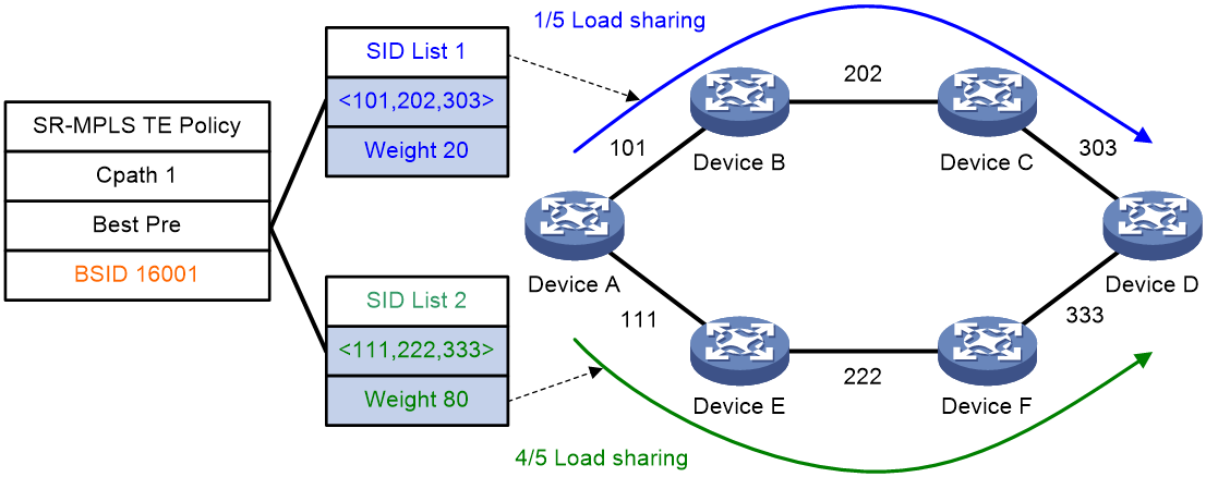
4. If the chosen candidate path has multiple SID lists, the traffic will be load shared based on the weight values among the subpaths identified by the SID lists. The load of SID list x is equal to Weight x/(Weight 1 + Weight 2 + … + Weight n).
For example, Device A in Figure 1 first chooses a valid SR-MPLS TE policy by BSID. Then, the device chooses a candidate path by preference. The candidate path has two valid SID lists: SID list 1 and SID list 2. The weight value of SID list 1 is 20 and the weight value of SID list 2 is 80. One fifth of the traffic will be forwarded through the subpath identified by SID list 1. Four fifth of the traffic will be forwarded through the subpath identified by SID list 2.
Figure 1 SR-MPLS TE policy routing diagram
SR-MPLS TE policy forwarding procedure
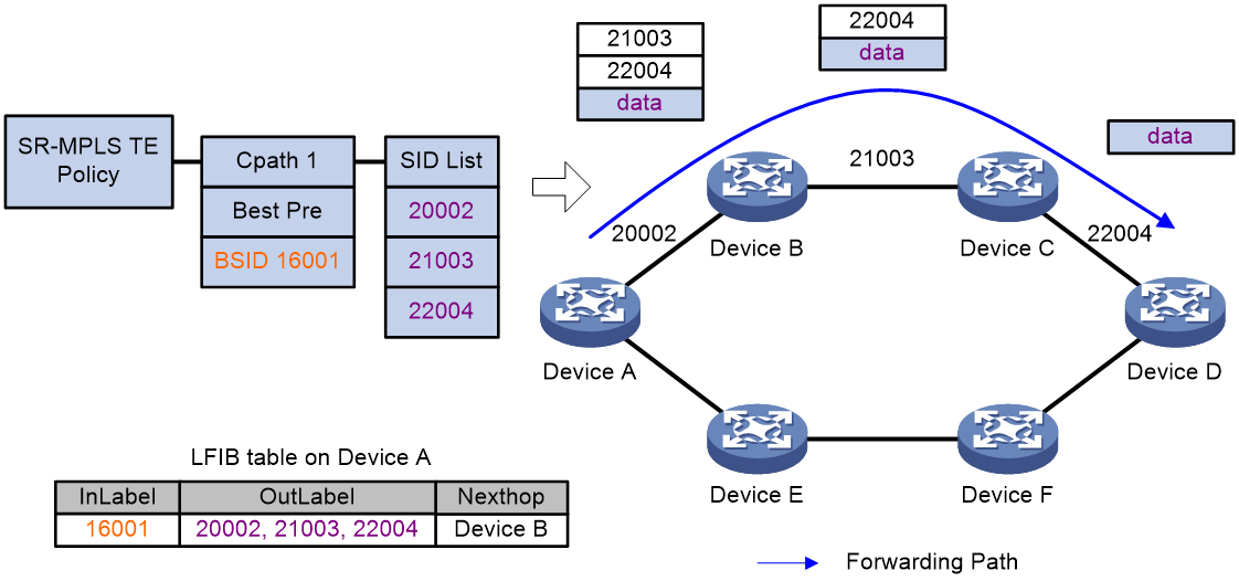
As shown in Figure 2, the SR-MPLS TE policy forwarding procedure is as follows:
1. After Device A receives a packet with the stack top label 16001, it searches its LFIB and determines that the label is a BSID. Then, Device A obtains the outgoing label stack and next hop (Device B), pops the BSID, pushes SID list {20002, 21003, 22004}, and forwards the packet to Device B. 20002 is the SID of the segment for a packet to travel from Device A to Device B. 21003 is the SID of the segment for a packet to travel from Device B to Device C. 22004 is the SID of the segment for a packet to travel from Device C to Device D.
2. After Device B receives the packet, it searches its LFIB by the incoming label and determines that the next hop is Device C. Then, Device B forwards the packet to Device C.
3. After Device C receives the packet, it searches its LFIB by the incoming label and determines that the next hop is Device D. Then, Device C forwards the packet to Device D.
4. After Device D receives the packet, it identifies whether the packet is carrying a label. If yes, Device D searches its LFIB to forward the packet. If not, Device D searches its IP FIB to forward the packet.
Figure 2 SR-MPLS TE policy forwarding diagram
Traffic steering to an SR-MPLS TE policy
You can steer traffic to an SR-MPLS TE policy for further forwarding based on the following criteria:
· BSID—Upon receiving a packet whose stack top label is a BSID, the device chooses an SR-MPLS TE policy based on the BSID to forward the packet.
· Color—The device searches for an SR-MPLS TE policy with the color value and endpoint that match the color extended community attribute and next hop of a BGP route. If a matching SR-MPLS TE policy is found, the device recurses the BGP route to that SR-MPLS TE policy. Then, packets matching the BGP route will be steered to the SR-MPLS TE policy for further forwarding.
· Tunnel policy—In an MPLS L3VPN or EVPN L3VPN, configure a tunnel policy that uses an SR-MPLS TE policy as the public tunnel to carry the VPN packets. For more information about tunnel policies, see MPLS Configuration Guide.
· DSCP value—Create color-to-DSCP mappings for an SR-MPLS TE policy group, and create a tunnel policy that binds a destination IP address to the SR-MPLS TE policy group. Upon receiving a packet with the specified destination IP address, the device searches for the SR-MPLS TE policy containing the color value mapped to the DSCP value of the packet. The device will use the SR-MPLS TE policy to forward the packet.
· Static route—Associate a static route with an SR-MPLS TE policy so that packets matching the static route will be steered to the SR-MPLS TE policy for forwarding.
· QoS policy—Redirect traffic to an SR-MPLS TE policy through a QoS policy. The device uses the SR-MPLS TE policy to forward the packets that match the traffic classes of the QoS policy. For more information about QoS policies, see the QoS configuration in ACL and QoS Configuration Guide.
· Flowspec—Redirect traffic to an SR-MPLS TE policy through a Flowspec rule. The device uses the SR-MPLS TE policy to forward the packets that match the Flowspec rule. For more information about Flowspec, see ACL and QoS Configuration Guide.
SR-MPLS TE policy CBTS
About SR-MPLS TE policy CBTS
SR-MPLS TE policy Class Based Tunnel Selection (CBTS) enables dynamic routing and forwarding of traffic with service class values over different SR-MPLS TE policy tunnels between the same tunnel headend and tailend. CBTS uses a dedicated tunnel for a certain class of service to implement differentiated forwarding for services.
How SR-MPLS TE policy CBTS works
SR-MPLS TE policy CBTS processes traffic mapped to a priority as follows:
1. Uses a traffic behavior to set a service class value for the traffic. For more information about setting a service class value in traffic behavior view, see the remark service-class command in ACL and QoS Command Reference.
2. Compares the service class value of the traffic with the service class values of the SR-MPLS TE policy tunnels and forwards the traffic to a matching tunnel.
SR-MPLS TE policy tunnel selection rules
SR-MPLS TE policy CBTS uses the following rules to select an SR-MPLS TE policy tunnel for the traffic to be forwarded:
· If an SR-MPLS TE policy tunnel has the same service class value as the traffic, CBTS uses this tunnel.
· If multiple SR-MPLS TE policy tunnels have the same service class value as the traffic, CBTS selects a tunnel based on the flow forwarding mode:
¡ If only one flow exists and flow-based forwarding is set, CBTS randomly selects a matching tunnel for packets of the same flow.
¡ If multiple flows exist or if only one flow exists but packet-based forwarding is set, CBTS uses all matching tunnels to load share the packets.
For more information about the flow identification and load sharing mode, see the ip load-sharing mode command in Layer 3—IP Services Command Reference.
· If the traffic does not match any SR-MPLS TE policy tunnels by service class value, CBTS randomly selects a tunnel from all SR-MPLS TE policy tunnels with the lowest forwarding priority. An SR-MPLS TE policy that has a smaller service class value has a lower forwarding priority. An SR-MPLS TE policy that is not configured with a service class value has the lowest priority.
SR-MPLS TE policy CBTS application scenario
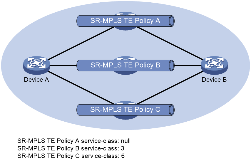
As shown in Figure 3, CBTS selects SR-MPLS TE policy tunnels for traffic from Device A to Device B as follows:
· Uses SR-MPLS TE policy B to forward traffic with service class value 3.
· Uses SR-MPLS TE policy C to forward traffic with service class value 6.
· Uses SR-MPLS TE policy A to forward traffic with service class value 4.
· Uses SR-MPLS TE policy A to forward traffic with no service class value.
Figure 3 SR-MPLS TE policy CBTS application scenario
SR-MPLS TE policy association with SBFD
Typically, SR-MPLS TE policies use SBFD to maintain policy state and detect path failures. By default, SBFD detects the SID lists for only the candidate path of the highest preference in an SR-MPLS TE policy.
Figure 4 SR-MPLS TE policy association with SBFD
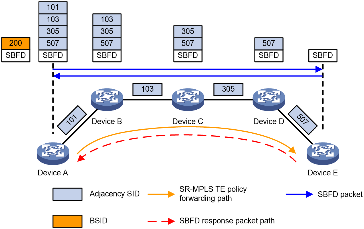
As shown in Figure 4, the SR-MPLS TE policy is associated with SBFD on source node Device A. The endpoint IP address is specified as the remote discriminator of the SBFD session. If the candidate path of the highest preference in the SR-MPLS TE policy has multiple SID lists, multiple SBFD sessions are established to detect the forwarding path for each SID list. All SBFD sessions use the same remote discriminator.
The SR-MPLS TE policy uses SBFD to detect the forwarding paths as follows:
1. The source node (Device A) sends an SBFD packet that encapsulates the target SID lists of the SR-MPLS TE policy.
2. Upon receiving the SBFD packet, the destination node (Device E) sends a response along the shortest path obtained through routing table lookup.
3. Upon receiving the SBFD response, Device A determines that the forwarding path for the SID list is available. If no response is received, Device A determines that the forwarding path is faulty. If all SID lists for the current candidate path are faulty, another candidate path takes over.
|
|
NOTE: Because SBFD responses are forwarded according to the IP routing table lookup, all SBFD sessions for the SR-MPLS TE policies that have the same source and destination nodes use the same path to send responses. A failure of the SBFD response path will cause all the SBFD sessions to be down and consequentially packets cannot be forwarded through the SR-MPLS TE policies. |
SR-MPLS TE policy hot standby
If an SR-MPLS TE policy has multiple valid candidate paths, the device chooses the candidate path with the greatest preference value. If the chosen path fails, the SR-MPLS TE policy must select another candidate path. During path reselection, packet loss might occur to affect service continuity.
The SR-TE hot standby feature can address this issue. This feature takes the candidate path with the greatest preference value as the primary path and that with the second greatest preference value as the standby path. As shown in Figure 5, when the forwarding paths corresponding to all SID lists of the primary path fails, the standby path immediately takes over to minimize service interruption.
Figure 5 SR-MPLS TE policy hot standby
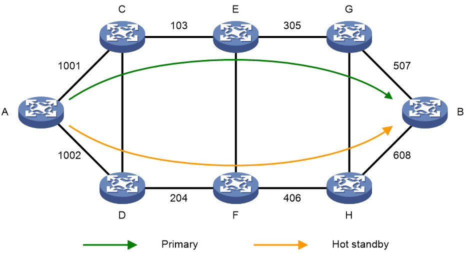
You can configure both the hot standby and SBFD features for an SR-MPLS TE policy. Use SBFD to detect the availability of the primary and standby paths specified for hot standby. If all SID lists of the primary path become unavailable, the standby path takes over and a path recalculation is performed. The standby path becomes the new primary path, and a new standby path is selected. If both the primary and standby paths fail, the SR-MPLS TE policy will calculate new primary and standby paths.
MP-BGP extension for SR-MPLS TE policy-based routing
To support SR-MPLS TE policies, MP-BGP increases the following definitions:
· BGP IPv4 SR policy address family.
· BGP IPv4 SR policy routes, which are also called SR-MPLS TE policy NLRI.
BGP IPv4 SR policy route information carries SR-MPLS TE policy settings, including the BSIDs, color values, endpoints, preference values, and weight values. After the device advertises BGP IPv4 SR policy routes to a peer, the peer can also use SR-MPLS TE policies to steer traffic.
The device supports the color extended community attribute. Upon receiving a packet that matches a route with the color extended community attribute, the device searches for an SR-MPLS TE policy that has the same color value as the route. If an SR-MPLS TE policy is found, the device forwards the packet based on the SR-MPLS TE policy. If not, the device uses the optimal route to forward the packet.
The color extended community attribute is in the format of 2-bit Color-Only flag:32-bit user-defined color value, for example, 10:3.
Restrictions and guidelines: SR-MPLS TE policy configuration
This feature is available only for the following cards:
|
Card category |
Cards |
|
CEPC |
CEPC-XP4LX, CEPC-XP24LX, CEPC-XP48RX, CEPC-CP4RX, CEPC-CP4RXA, CEPC-CP4RX-L, CEPC-CQ8L, CEPC-CQ8LA, CEPC-CQ8L1A, CEPC-CQ16L1 |
|
CSPEX |
CSPEX-1304X, CSPEX-1404X, CSPEX-1502X, CSPEX-1504X, CSPEX-1504XA, CSPEX-1602X, CSPEX-1602XA, CSPEX-1804X, CSPEX-1512X, CSPEX-1612X, CSPEX-1812X, CSPEX-1802X, CSPEX-1802XA, CSPEX-2612XA, CSPEX-1812X-E, CSPEX-2304X-G, CSPEX-1502XA |
|
SPE |
RX-SPE200, RX-SPE200-E |
|
OAA |
IM-NGFWX-IV |
SR-MPLS TE policy configuration tasks at a glance
To configure an SR-MPLS TE policy, perform the following tasks:
1. Create an SR-MPLS TE policy and configure the settings:
a. Creating an SR-MPLS TE policy
b. Configuring SR-MPLS TE policy attributes
c. (Optional.) Shutting down an SR-MPLS TE policy
d. Configuring a candidate path and a SID list for the path
e. (Optional.) Enabling the device to distribute SR-MPLS TE policy path information to BGP-LS
2. (Optional.) Configuring BGP to advertise BGP IPv4 SR policy routes
a. Enabling BGP to advertise BGP IPv4 SR policy routes
b. Configuring BGP to redistribute routes from the
c. (Optional.) Advertising BGP IPv4 SR policy routes to EBGP peers
d. (Optional.) Filtering BGP IPv4 SR policy routes by router ID
e. (Optional.) Enabling validity check for BGP IPv4 SR policy routes
f. (Optional.) Configuring BGP to control BGP IPv4 SR policy route selection and advertisement
g. (Optional.) Maintaining BGP sessions
3. Steering traffic to an SR-MPLS TE policy
4. (Optional.) Configuring SR-MPLS TE policy high availability
¡ Enabling SBFD for SR-MPLS TE policies
¡ Enabling hot standby for SR-MPLS TE policies
¡ Configuring path switchover and deletion delays for SR-MPLS TE policies
¡ Setting the delay time for bringing up SR-MPLS TE policies
5. (Optional.) Configuring SR-MPLS TE policy CBTS
6. (Optional.) Maintaining SR-MPLS TE policies
¡ Enabling SR-MPLS TE policy logging
¡ Enabling SNMP notifications for SR-MPLS TE policies
¡ Configuring traffic forwarding statistics for SR-MPLS TE policies
Creating an SR-MPLS TE policy
1. Enter system view.
system-view
2. Enter segment routing view.
segment-routing
3. Enter SR TE view.
traffic-engineering
4. Create an SR-MPLS TE policy and enter its view.
policy policy-name
Configuring SR-MPLS TE policy attributes
About this task
An SR-MPLS TE policy is identified by the following items: BSID, color, and endpoint. Upon receiving a packet whose stack top label is a BSID, the device chooses an SR-MPLS TE policy based on the BSID to forward the packet.
You can bind a BSID to the policy manually, or set only the color and endpoint attributes of the policy so the system automatically assigns a BSID to the policy. If you use both methods, the manually bound BSID takes effect.
Restrictions and guidelines
If you configure an MPLS label as the BSID but the label is not in the range of the SRGB or SRLB or is already used by a protocol, the configuration does not take effect. For more information about SRGB or SRLB, see "Configuring SR-MPLS."
Different SR-MPLS TE policies cannot have the same color and endpoint address combination.
Procedure
1. Enter system view.
system-view
2. Enter segment routing view.
segment-routing
3. Enter the SR TE view.
traffic-engineering
4. Enter SR-MPLS TE policy view.
policy policy-name
5. Bind a BSID to the policy.
binding-sid mpls mpls-label
6. Set the color and endpoint attributes.
color color-value end-point ipv4 ipv4-address
Shutting down an SR-MPLS TE policy
About this task
If multiple SR-MPLS TE policies exist on the device, you can shut down unnecessary SR-MPLS TE policies to prevent them from affecting traffic forwarding.
Procedure
1. Enter system view.
system-view
2. Enter segment routing view.
segment-routing
3. Enter SR TE view.
traffic-engineering
4. Enter SR-MPLS TE policy view.
policy policy-name
5. Shut down the SR-MPLS TE policy.
shutdown
By default, an SR-MPLS TE policy is not administratively shut down.
Configuring a candidate path and a SID list for the path
About this task
After you add nodes to a SID list, the system will sort the nodes in ascending order of node index.
Procedure
1. Enter system view.
system-view
2. Enter segment routing view.
segment-routing
3. Enter SR TE view.
traffic-engineering
4. Create a SID list and enter its view.
segment-list segment-list-name
5. Add a node to the SID list.
index index-number mpls label label-value
6. Return to system view.
quit
7. Enter SR-MPLS TE policy view.
policy policy-name
8. Create and enter SR-MPLS TE policy candidate path view.
candidate-paths
9. Set the preference for a candidate path and enter candidate path preference view.
preference preference-value
By default, no candidate path preferences are set.
Each preference represents a candidate path.
10. Specify an explicit path for the candidate path.
explicit segment-list segment-list-name [ weight weight-value ]
A candidate path can have multiple SID lists.
Enabling the device to distribute SR-MPLS TE policy path information to BGP-LS
About this task
This feature enables the device to distribute SR-MPLS TE policy candidate path information to BGP-LS. BGP-LS advertises the SR-MPLS TE policy candidate path information to meet application requirements.
Prerequisites
Before you configure this feature, enable the device to exchange LS information with the related peer or peer group. For more information about the LS exchange capability, see the BGP LS configuration in Layer 3—IP Routing Configuration Guide.
Procedure
1. Enter system view.
system-view
2. Enter segment routing view.
segment-routing
3. Enter SR TE view.
traffic-engineering
4. Enable the device to distribute SR-MPLS TE policy candidate path information to BGP-LS.
distribute bgp-ls
By default, the device cannot distribute SR-MPLS TE policy candidate path information to BGP-LS.
Configuring BGP to advertise BGP IPv4 SR policy routes
Restrictions and guidelines for BGP IPv4 SR policy routes advertisement
For more information about BGP commands, see Layer 3—IP Routing Commands.
Enabling BGP to advertise BGP IPv4 SR policy routes
1. Enter system view.
system-view
2. Configure a global router ID.
router id router-id
By default, no global router ID is configured.
3. Enable a BGP instance and enter its view.
bgp as-number [ instance instance-name ]
By default, BGP is disabled and no BGP instances exist.
4. Configure a peer.
peer { group-name | ipv4-address [ mask-length ] | ipv6-address [ prefix-length ] } as-number as-number
5. Create the BGP IPv4 SR policy address family and enter its view.
address-family ipv4 sr-policy
6. Enable BGP to exchange SR-MPLS TE policy routing information with the peer or peer group.
peer { group-name | ipv4-address [ mask-length ] | ipv6-address [ prefix-length ] } enable
By default, the device cannot use BGP to exchange SR-MPLS TE policy routing information with a peer or peer group.
Configuring BGP to redistribute routes from the SR-MPLS TE policy
About this task
After you configure BGP to redistribute BGP IPv4 SR policy routes, the system will redistribute the local BGP IPv4 SR policy routes to the BGP routing table and advertise the routes to IBGP peers. Then, the peers can forward traffic based on the SR-MPLS TE policy.
Procedure
1. Enter system view.
system-view
2. Enter BGP instance view.
bgp as-number [ instance instance-name ]
3. Enter BGP IPv4 SR policy address family view.
address-family ipv4 sr-policy
4. Enable BGP to redistribute routes from the SR-MPLS TE policy.
import-route sr-policy
By default, BGP does not redistribute BGP IPv4 SR policy routes.
Advertising BGP IPv4 SR policy routes to EBGP peers
About this task
By default, only IBGP peers exchange BGP IPv4 SR policy routes. Perform this task to advertise BGP IPv4 SR policy routes to EBGP peers.
Procedure
1. Enter system view.
system-view
2. Enter BGP instance view.
bgp as-number [ instance instance-name ]
3. Enter BGP IPv4 SR policy address family view.
address-family ipv4 sr-policy
4. Advertise BGP IPv4 SR policy routes to EBGP peers.
advertise ebgp enable
By default, BGP IPv4 SR policy routes are not advertised to EBGP peers.
Filtering BGP IPv4 SR policy routes by router ID
About this task
When a large number of BGP IPv4 SR policy routes exist in the network, perform this task to enable the device to process only specific BGP IPv4 SR policy routes.
The Router ID filtering feature enables the device to check the Route Target attribute of a received BGP IPv4 SR policy route.
· If the Route Target attribute contains the Router ID of the local device, the device accepts the route and generates an SR-MPLS TE policy accordingly.
· If the Route Target attribute does not contain the Router ID of the local device, the device processes the route as follows:
¡ If the bgp-rib-only keyword is not specified in the command for enabling Router ID filtering, the device drops the route.
¡ If the bgp-rib-only keyword is specified, the device accepts the route but does not generate the corresponding SR-MPLS TE policy.
When the controller advertises a BGP IPv4 SR policy route to the source node, the transit nodes between the controller and the source node only need to forward the BGP IPv4 SR policy route. They do not need to generate the SR-MPLS TE policy. In this case, you can execute the router-id filter bgp-rib-only command on the transit nodes. Then, when a transit node receives a BGP IPv4 SR policy route, it forwards the route even if the route's Route Target attribute does not contain the Router ID of the local device. Meanwhile, it does not generate an SR-MPLS TE policy in order to not affect packet forwarding.
Restrictions and guidelines
To avoid incorrect route learning or filtering, configure a routing policy to add an appropriate RT attribute to BGP IPv4 SR policy routes before using this feature.
Procedure
1. Enter system view.
system-view
2. Enter BGP instance view.
bgp as-number [ instance instance-name ]
3. Enter BGP IPv4 SR policy address family view.
address-family ipv4 sr-policy
4. Enable BGP IPv4 SR policy route filtering by router ID.
router-id filter [ bgp-rib-only ]
By default, BGP IPv4 SR policy route filtering by router ID is disabled.
Enabling validity check for BGP IPv4 SR policy routes
About this task
After validity check is enabled for BGP IPv4 SR policy routes, the device determines that a BGP IPv4 SR policy route is invalid and will not select the route if the route does not contain the IPv4 address format RT extended community attribute or the NO_ADVERTISE community attribute.
You can configure this feature on the RR in networks where the controller and the RR establish BGP peer relationship and the RR establishes BGP peer relationship with the source nodes of multiple SR-MPLS TE policies.
The RR checks whether the SR policy routes issued by the controller carry the IPv4 address format RT extended community attribute or the NO_ADVERTISE community attribute. If yes, the RR accepts the routes and reflects the routes that do not carry the NO_ADVERTISE attribute to the source nodes of the SR-MPLS TE policies.
On the source nodes, you can use the router-id filter command to enable BGP IPv4 SR policy route filtering by router ID. After a source node receives a BGP IPv4 SR policy route, it compares the local router ID with the IPv4 address in the RT attribute of the route. If they are the same, the source node accepts the route. If they are different, the source node drops the route.
Procedure
1. Enter system view.
system-view
2. Enter BGP instance view.
bgp as-number [ instance instance-name ]
3. Enter BGP IPv4 SR policy address family view.
address-family ipv4 sr-policy
4. Enable validity check for BGP IPv4 SR policy routes.
validation-check enable
By default, validity check for BGP IPv4 SR policy routes is disabled. The device does not check the validity of the BGP IPv4 SR policy routes received from the peer or peer group.
Configuring BGP to control BGP IPv4 SR policy route selection and advertisement
1. Enter system view.
system-view
2. Enter BGP instance view.
bgp as-number [ instance instance-name ]
3. Enter BGP IPv4 SR policy address family view.
address-family ipv4 sr-policy
4. Specify the local router as the next hop for routes sent to a peer or peer group.
peer { group-name | ipv4-address [ mask-length ] } next-hop-local
By default, BGP sets the local router as the next hop for all routes sent to an EBGP peer or peer group. BGP does not set the local router as the next hop for routes sent to an IBGP peer or peer group.
5. Allow a local AS number to exist in the AS_PATH attribute of routes from a peer or peer group, and to set the number of times the local AS number can appear.
peer { group-name | ipv4-address [ mask-length ] } allow-as-loop [ number ]
By default, the local AS number is not allowed to exist in the AS_PATH attribute of routes from a peer or peer group.
6. Specify a preferred value for routes received from a peer or peer group.
peer { group-name | ipv4-address [ mask-length ] } preferred-value value
By default, the preferred value is 0 for routes received from a peer or peer group.
7. Set the maximum number of routes that can be received from a peer or peer group.
peer { group-name | ipv4-address [ mask-length ] } route-limit prefix-number [ { alert-only | discard | reconnect reconnect-time } | percentage-value ] *
By default, the number of routes that can be received from a peer or peer group is not limited.
8. Configure the device as a route reflector and specify a peer or peer group as a client.
peer { group-name | ipv4-address [ mask-length ] } reflect-client
By default, neither the route reflector nor the client is configured.
9. Specify a prefix list to filter routes received from or advertised to a peer or peer group.
peer { group-name | ipv4-address [ mask-length ] } prefix-list ipv4-prefix-list-name { export | import }
By default, no prefix list based filtering is configured.
10. Apply a routing policy to routes incoming from or outgoing to a peer or peer group.
peer { group-name | ipv4-address [ mask-length ] } route-policy route-policy-name { export | import }
By default, no routing policy is applied to routes incoming from or outgoing to a peer or peer group.
11. Advertise the COMMUNITY attribute to a peer or peer group.
peer { group-name | ipv4-address [ mask-length ] } advertise-community
By default, BGP does not advertise the COMMUNITY attribute to any peers or peer groups.
12. Advertise the extended community attribute to a peer or peer group.
peer { group-name | ipv4-address [ mask-length ] } advertise-ext-community
By default, BGP does not advertise the extended community attribute to any peers or peer groups.
13. Advertise the Large Community attribute to a peer or peer group.
peer { group-name | ipv4-address [ mask-length ] } advertise-large-community
By default, BGP does not advertise the Large Community attribute any peers or peer groups.
14. Assign a peer or peer group a high priority in BGP route selection.
peer { group-name | ipv4-address [ mask-length ] } high-priority
By default, a peer or peer group does not have a high priority in BGP route selection.
Maintaining BGP sessions
To maintain BGP sessions, execute the following commands in user view:
· Reset BGP sessions for the BGP IPv4 SR policy address family.
reset bgp [ instance instance-name ] { as-number | ipv4-address [ mask-length ] | all | external | group group-name | internal } ipv4 sr-policy
· Manually soft-reset BGP sessions for the BGP IPv4 SR policy address family.
refresh bgp [ instance instance-name ] { ipv4-address [ mask-length ] | all | external | group group-name | internal } { export | import } ipv4 sr-policy
Steering traffic to an SR-MPLS TE policy
Configuring the traffic steering mode
Restrictions and guidelines
This feature does not take effect in L2VPN networks.
Procedure
1. Enter system view.
system-view
2. Enter BGP instance view.
bgp as-number [ instance instance-name ]
3. Configure the SR-MPLS TE policy traffic steering mode.
sr-policy steering { disable | policy-based }
By default, traffic is steered to an SR-MPLS TE policy based on the color value.
After the policy-based keyword is specified, traffic is steered based on tunnel binding policy, color, and load sharing policy, in descending order of priority.
Configuring color-based traffic steering
About this task
To steer traffic to an SR-MPLS TE policy based on colors, you can configure a color extended community for routes that do not carry a color extended community in the following methods:
· Configure a routing policy to add a color value to routes.
· Configure a default color value.
The color value specified in the routing policy is preferred.
Restrictions and guidelines
The default color value applies only to the VPN routes or public network routes learned from a remote PE.
The default color value is used only for SR-MPLS TE policy traffic steering. It does not used in route advertisement.
Configuring a routing policy to add a color value to routes
1. Enter system view.
system-view
2. Enter routing policy node view.
route-policy route-policy-name { deny | permit } node node-number
3. Set the color extended community attribute for BGP routes.
apply extcommunity color color [ additive ]
By default, no BGP route attributes are configured.
4. Return to system view.
quit
5. Enter BGP instance view.
bgp as-number [ instance instance-name ]
6. Enter BGP IPv4 unicast address family view, BGP IPv6 unicast address family view, BGP VPNv4 address family view, or BGP VPNv6 address family view.
¡ Enter BGP IPv4 unicast address family view.
address-family ipv4 [ unicast ]
¡ Enter BGP IPv6 unicast address family view.
address-family ipv6 [ unicast ]
¡ Enter BGP VPNv4 address family view.
address-family vpnv4
¡ Enter BGP VPNv6 address family view.
address-family vpnv6
7. Specify a routing policy to filter routes advertised to or received from a peer or peer group.
peer { group-name | ipv4-address [ mask-length ] } route-policy route-policy-name { export | import }
By default, no routing policy is specified.
Configuring a default color value for VPN routes
1. Enter system view.
system-view
2. Enter VPN instance view.
ip vpn-instance vpn-instance-name [ index vpn-index ]
3. Enter VPN instance IPv4 address family view or VPN instance IPv6 address family view.
¡ Enter VPN instance IPv4 address family view.
address-family ipv4
¡ Enter VPN instance IPv6 address family view.
address-family ipv6
4. Configure a default color value for L3VPN route recursion to an SR-MPLS TE policy.
default-color color-value [ evpn ]
By default, no default color is configured for L3VPN route recursion to an SR-MPLS TE policy.
Configuring a default color value for public network routes
1. Enter system view.
system-view
2. Enter pubic instance view.
ip public-instance
3. Enter public instance IPv4 or IPv6 address family view.
¡ Enter public instance IPv4 address family view
address-family ipv4
¡ Enter public instance IPv6 address family view.
address-family ipv6
4. Configure a default color value for public network route recursion to an SR-MPLS TE policy.
default-color color-value
By default, no default color value is configured for public network route recursion to an SR-MPLS TE policy.
Configuring tunnel policy-based traffic steering
1. Enter system view.
system-view
2. Create a tunnel policy and enter tunnel policy view.
tunnel-policy tunnel-policy-name [ default ]
3. Configure the tunnel policy. Choose one option as needed:
¡ Configure an SR-MPLS TE policy tunnel as a preferred tunnel.
preferred-path sr-policy name sr-policy-name
By default, no preferred tunnels are configured.
¡ Configure a tunnel load sharing policy.
select-seq sr-policy load-balance-number number
By default, no tunnel load sharing policies are configured.
For more information about the commands, see MPLS Command Reference.
4. Return to system view.
quit
5. Enter VPN instance view, VPN instance IPv4 address family view, or VPN instance IPv6 address family view.
¡ Enter VPN instance view.
ip vpn-instance vpn-instance-name
¡ Execute the following commands in sequence to enter VPN instance IPv4 address family view.
ip vpn-instance vpn-instance-name
address-family ipv4
¡ Execute the following commands in sequence to enter VPN instance IPv6 address family view.
ip vpn-instance vpn-instance-name
address-family ipv6
6. Apply a tunnel policy to the VPN instance.
tnl-policy tunnel-policy-name
By default, no tunnel policy is applied to the VPN instance.
For more information about this command, see MPLS Command Reference.
Configuring DSCP-based traffic steering
About this task
Each SR-MPLS TE policy in an SR-MPLS TE policy group has a different color attribute value. By configuring color-to-DSCP mappings for an SR-MPLS TE policy group, you associate DSCP values to SR-MPLS TE policies. This allows IP packets containing a specific DSCP value to be steered to the corresponding SR-MPLS TE policy for further forwarding.
Restrictions and guidelines
You can map the color values of only valid SR-MPLS TE policies to DSCP values.
You can configure color-to-DSCP mappings separately for the IPv4 address family and IPv6 address family. For a specific address family, a DSCP value can be mapped to only one color value.
Use the color match dscp default command to specify the default SR-MPLS TE policy for an address family. If no SR-MPLS TE policy in an SR-MPLS TE policy group matches a specific DSCP value, the default SR-MPLS TE policy is used to forward packets containing the DSCP value. Only one default SR-MPLS TE policy can be specified for an address family.
When the device receives an IPv4 or IPv6 packet that does not match any color-to-DSCP mapping, the device selects a valid SR-MPLS TE policy for the packet in the following order:
1. The default SR-MPLS TE policy specified for the same address family as the packet.
2. The default SR-MPLS TE policy specified for the other address family.
3. The SR-MPLS TE policy mapped to the smallest DSCP value in the same address family as the packet.
4. The SR-MPLS TE policy mapped to the smallest DSCP value in the other address family.
Procedure
1. Enter system view.
system-view
2. Enter segment routing view.
segment-routing
3. Create and enter the SR TE view.
traffic-engineering
4. Create an SR-MPLS TE policy group and enter its view.
policy-group group-id
5. Configure the endpoint IP address for the SR-MPLS TE policy group.
end-point ipv4 ipv4-address
By default, no endpoint IP address is configured for the SR-MPLS TE policy group.
The SR-MPLS TE policies added to the SR-MPLS TE policy group must use the same endpoint IP address as the SR-MPLS TE policy group.
6. Create color-to-DSCP mappings for the SR-MPLS TE policy group.
color color-value match dscp { ipv4 | ipv6 } dscp-value-list
color color-value match dscp { ipv4 | ipv6 } default
By default, no color-to-DSCP mappings are created for the SR-MPLS TE policy group.
DSCP-based traffic steering cannot function if no color-to-DSCP mappings are created.
7. Return to system view.
quit
8. Create a tunnel policy and enter tunnel policy view.
tunnel-policy tunnel-policy-name [ default ]
9. Bind the SR-MPLS TE policy group to a destination IP address.
binding-destination dest-ip-address sr-policy group sr-policy-group-id [ ignore-destination-check ] [ down-switch ]
By default, a tunnel policy does not bind any SR-MPLS TE policy group to a destination IP address.
For more information about the command, see MPLS Command Reference.
Configuring static route-based traffic steering
Restrictions and guidelines
After you configure this feature, execute the route-replicate command in public instance IPv4 address family view to replicate the routes of the specified VPN instance to the public network. The public network can then use the VPN routes to forward user traffic.
Procedure
1. Enter system view.
system-view
2. Configure a static route and associate it with an SR-MPLS TE policy.
tunnel-policy tunnel-policy-name [ default ]
Public network:
ip route-static dest-address { mask-length | mask } sr-policy policy-name [ preference preference ] [ tag tag-value ] [ description text ]
VPN:
ip route-static vpn-instance s-vpn-instance-name dest-address { mask-length | mask } sr-policy policy-name [ preference preference ] [ tag tag-value ] [ description text ]
By default, no static route is configured.
For more information about the commands, see Layer 3—IP Routing Command Reference.
Configuring QoS policy-based traffic steering
About this task
To resolve congestion for certain IPv4 public network traffic, you can create a traffic class to identify traffic, and redirect matching traffic to an SR-MPLS TE policy based on endpoint and color. If traffic fails to match the redirection rule or the SR-MPLS TE policy fails, the traffic class becomes invalid, and the traffic is forwarded according to IPv4 routing table lookup.
Restrictions and guidelines
For more information about QoS policy commands, see QoS commands in ACL and QoS Command Reference.
Procedure
a. Enter system view.
system-view
b. Create a traffic class and enter traffic class view.
traffic classifier classifier-name [ operator { and | or } ]
c. Configure a match criterion.
if-match [ not ] match-criteria
By default, no match criterion is configured.
For more information, see the if-match command in ACL and QoS Command Reference.
a. Create a traffic behavior and enter traffic behavior view.
traffic behavior behavior-name
b. Redirect matching traffic to an SR-MPLS TE policy.
redirect sr-policy endpoint color
By default, no action is configured for a traffic behavior.
a. Create a QoS policy and enter QoS policy view.
qos policy policy-name
b. Associate a traffic class with a traffic behavior to create a class-behavior association in the QoS policy.
classifier classifier-name behavior behavior-name
By default, a traffic class is not associated with a traffic behavior.
c. Return to system view.
quit
d. Apply the QoS policy.
For more information, see QoS policy configuration in ACL and QoS Configuration Guide.
By default, the QoS policy is not applied.
Configuring Flowspec rule-based traffic steering
Creating and activating an IPv4 Flowspec rule
1. Enter system view.
system-view
2. Create an IPv4 Flowspec rule.
flow-route flowroute-name
3. Configure a match criterion.
if-match match-criteria
4. Apply an action that redirects packets to an SR-MPLS TE policy.
apply redirect next-hop ipv4-address color color
By default, no action is configured.
5. Commit the match criterion and action.
commit
By default, match criteria and actions are not committed.
Applying an IPv4 Flowspec rule to the public network
1. Enter system view.
system-view
2. Enter Flowspec view.
flowspec
3. Create a Flowspec IPv4 address family for the public network and enter its view.
address-family ipv4
4. Apply an IPv4 Flowspec rule to the public network. Choose one option as needed:
¡ Apply an IPv4 Flowspec rule.
flow-route flowroute-name
By default, no IPv4 Flowspec rule is applied to the public network.
¡ Apply an IPv4 Flowspec rule and associate it with a Flowspec interface group.
flow-route flowroute-name flow-interface-group group-id
By default, no Flowspec interface group is associated with an IPv4 Flowspec rule.
Applying an IPv4 Flowspec rule to a VPN instance
1. Enter system view.
system-view
2. Configure a VPN instance.
a. Create a VPN instance and enter VPN instance view.
ip vpn-instance vpn-instance-name
b. Configure an RD for the VPN instance.
route-distinguisher route-distinguisher
By default, no RD is configured for a VPN instance.
c. Configure route targets for the VPN instance.
vpn-target { vpn-target&<1-8> [ both | export-extcommunity | import-extcommunity ] }
By default, no route targets are configured.
For more information about the ip vpn-instance, route-distinguisher, and vpn-target commands, see MPLS L3VPN commands in MPLS Command Reference.
3. Enter the IPv4 Flowspec address family view of the VPN instance.
address-family ipv4 flowspec
4. Configure an RD for the IPv4 Flowspec address family.
route-distinguisher route-distinguisher
By default, no RD is configured for the IPv4 Flowspec address family.
5. Configure route targets for the IPv4 Flowspec address family.
vpn-target vpn-target&<1-8> [ both | export-extcommunity | import-extcommunity ]
By default, no route targets are configured for the IPv4 Flowspec address family.
The route targets configured must be the same as the route targets configured previously for the VPN instance.
6. Execute the quit command twice to return to system view.
7. Enter Flowspec view.
flowspec
8. Create a Flowspec IPv4 address family and associate the address family with the VPN instance.
address-family ipv4 vpn-instance vpn-instance-name
9. Apply an IPv4 Flowspec rule to the Flowspec IPv4 VPN instance address family. Choose one option as needed:
¡ Apply an IPv4 Flowspec rule.
flow-route flowroute-name
By default, no IPv4 Flowspec rule is applied to a Flowspec IPv4 VPN instance address family.
¡ Apply an IPv4 Flowspec rule and associate it with a Flowspec interface group.
flow-route flowroute-name flow-interface-group group-id
By default, no Flowspec interface group is associated with an IPv4 Flowspec rule.
Enabling BGP to distribute IPv4 Flowspec rules
1. Enter system view.
system-view
2. Enter BGP instance view:
bgp as-number [ instance instance-name ]
3. Enter BGP IPv4 Flowspec address family view, BGP-VPN IPv4 Flowspec address family view, or BGP VPNv4 Flowspec address family view:
¡ Enter BGP IPv4 Flowspec address family view to distribute public network IPv4 Flowspec rules:
address-family ipv4 flowspec
¡ Enter BGP-VPN IPv4 Flowspec address family view to distribute private network IPv4 Flowspec rules:
ip vpn-instance vpn-instance-name
address-family ipv4 flowspec
¡ Enter BGP VPNv4 Flowspec address family view to distribute VPNv4 Flowspec rules:
address-family vpnv4 flowspec
4. Enable BGP Flowspec peers to exchange routing information.
peer { group-name | ipv4-address [ mask-length ] | ipv6-address [ prefix-length ] } enable
By default, BGP Flowspec peers cannot exchange routing information.
Enabling SBFD for SR-MPLS TE policies
Restrictions and guidelines
You can enable SBFD for all SR-MPLS TE policies globally in SR TE view or for a specific SR-MPLS TE policy in SR-MPLS TE policy view. The policy-specific configuration takes precedence over the global configuration. An SR-MPLS TE policy uses the global configuration only when it has no policy-specific configuration.
Prerequisites
Before you configure this feature, execute the mpls bfd enable command to enable MPLS BFD. For more information about the mpls bfd enable command, see MPLS OAM commands in MPLS Command Reference.
Procedure
1. Enter system view.
system-view
2. Enter segment routing view.
segment-routing
3. Enter SR TE view.
traffic-engineering
4. Enable SBFD for all SR-MPLS TE policies.
sr-policy sbfd enable [ remote remote-id ] [ template template-name ] [ backup-template backup-template-name ]
By default, SBFD is disabled for all SR-MPLS TE policies.
5. (Optional.) Configure SBFD detection timer parameters.
sr-policy sbfd timer { detect-multiplier multiplier-value | min-tx-interval transmit-interval }
By default, no SBFD detection timer parameters are configured.
6. (Optional.) Globally enable BFD session down events to trigger SR-MPLS TE policy path reselection.
sr-policy bfd trigger path-down enable
By default, this feature is disabled.
7. (Optional.) Configure the delay time for the device to notify an SR-MPLS TE policy of the BFD/SBFD session down event.
sr-policy bfd first-fail-timer seconds
By default, the delay time for the device to notify an SR-MPLS TE policy of the BFD/SBFD session down event is 60 seconds.
8. Enter SR-MPLS TE policy view.
policy policy-name
9. Configure SBFD for the SR-MPLS TE policy.
sbfd { disable | enable [ remote remote-id ] [ template template-name ] [ backup-template backup-template-name ] }
By default, SBFD is not configured for an SR-MPLS TE policy.
10. (Optional.) Enable BFD session down events to trigger candidate path reselection for the SR-MPLS TE policy.
bfd trigger path-down { disable | enable }
By default, this feature is not configured for an SR-MPLS TE policy, and the configuration in SR TE view applies.
Enabling hot standby for SR-MPLS TE policies
Restrictions and guidelines
You can enable hot standby for all SR-MPLS TE policies globally in SR TE view or for a specific SR-MPLS TE policy in SR-MPLS TE policy view. The policy-specific configuration takes precedence over the global configuration. An SR-MPLS TE policy uses the global configuration only when it has no policy-specific configuration.
Procedure
1. Enter system view.
system-view
2. Enter segment routing view.
segment-routing
3. Enter SR TE view.
traffic-engineering
4. Enable hot standby for all SR-MPLS TE policies.
sr-policy backup hot-standby enable
By default, hot standby is disabled for all SR-MPLS TE policies.
5. Enter SR-MPLS TE policy view.
policy policy-name
6. Configure hot standby for the SR-MPLS TE policy.
backup hot-standby { disable | enable }
By default, hot standby is not configured for an SR-MPLS TE policy.
Configuring path switchover and deletion delays for SR-MPLS TE policies
About this task
The switchover delay and deletion delay mechanism is used to avoid traffic forwarding failure during a forwarding path (SID list) switchover.
When updating an SR-MPLS TE policy forwarding path, the device first establishes the new forwarding path before it deletes the old one. During the new path setup process, the device uses the old path to forward traffic until the switchover delay timer expires. When the switchover delay timer expires, the device switches traffic to the new path. The old path is deleted when the deletion delay timer expires.
To apply the switchover delay and deletion delay, the old and new forwarding paths of the SR-MPLS TE policy must both be up. When the old forwarding path goes down, traffic is switched to the new path immediately without waiting for the switchover delay time.
Procedure
1. Enter system view.
system-view
2. Enter segment routing view.
segment-routing
3. Enter SR TE view.
traffic-engineering
4. Configure the switchover delay time and deletion delay time for the SR-MPLS TE policy forwarding path.
sr-policy switch-delay switch-delay-time delete-delay delete-delay-time
By default, the switchover delay time and deletion delay time for the SR-MPLS TE policy forwarding path is 5000 milliseconds and 20000 milliseconds, respectively.
Setting the delay time for bringing up SR-MPLS TE policies
About this task
After an SR-MPLS TE policy recovers from a fault, the device waits for the delay time before bringing up the SR-MPLS TE policy. This is to ensure that the fault is completely removed so as to avoid packet loss caused by SR-MPLS TE policy flapping.
After this command is executed, the device starts different delay timers for an SR-MPLS TE policy according to the SBFD configuration for the SR-MPLS TE policy.
· If SBFD is not enabled, the device starts an LSP delay timer when the SID list state changes from Down to Up.
· If SBFD is enabled, the device starts an SBFD delay timer when the SBFD session state changes from Down to Up.
Restrictions and guidelines
To view the SBFD configuration, SID list state, and SBFD session state, execute the display segment-routing te policy command.
Set a proper SR-MPLS TE policy up delay time according to your network conditions. A very long delay time will cause an SR-MPLS TE policy to be unable to process user traffic for a long time.
You can set the delay time for all SR-MPLS TE policies globally in SR TE view or for a specific SR-MPLS TE policy in SR-MPLS TE policy view. The policy-specific configuration takes precedence over the global configuration. An SR-MPLS TE policy uses the global configuration only when it has no policy-specific configuration.
If you execute this command for multiple times, the most recent configuration takes effect. A new delay time setting does not apply to the SR-MPLS TE policies that are already in a policy-up delay process.
Procedure
1. Enter system view.
system-view
2. Enter segment routing view.
segment-routing
3. Enter SR TE view.
traffic-engineering
4. Set the policy-up delay time for all SR-MPLS TE policies.
sr-policy up-delay delay-time
By default, the device does not delay bringing up SR-MPLS TE policies.
5. Enter SR-MPLS TE policy view.
policy policy-name
6. Set the policy-up delay time for the SR-MPLS TE policy.
up-delay delay-time
By default, no policy-up delay time is set for an SR-MPLS TE policy and the policy-up delay time set in SR TE view applies.
Configuring SR-MPLS TE policy CBTS
Prerequisites
Before configuring CBTS, you must configure a QoS traffic behavior to mark the MPLS TE service class values for packets by using the remark service-class command. For more information, see QoS policy commands in ACL and QoS Command Reference.
Procedure
1. Enter system view.
system-view
2. Enter segment routing view.
segment-routing
3. Enter SR TE view.
traffic-engineering
4. Enter SR-MPLS TE policy view.
policy policy-name
5. Set a service class value for the SR-MPLS TE policy.
service-class service-class-value
By default, no service class value is set for an SR-MPLS TE policy. An SR-MPLS TE policy uses service class 255, which has the lowest forwarding priority.
Enabling SR-MPLS TE policy logging
Abou this task
This feature enables the device to log SR-MPLS TE policy state changes to facilitate audit of SR-MPLS TE policy operations. The SR-MPLS TE policy log messages are sent to the information center and output as configured in the information center. For more information about information center, see Network Management and Monitoring Configuration Guide.
Procedure
1. Enter system view.
system-view
2. Enter segment routing view.
segment-routing
3. Enter SR TE view.
traffic-engineering
4. Enable SR-MPLS TE policy logging.
sr-policy log enable
By default, SR-MPLS TE policy logging is disabled.
Enabling SNMP notifications for SR-MPLS TE policies
Abou this task
This feature enables the device to send SNMP notifications about state changes of SR-MPLS TE policies. For SNMP notifications to be sent correctly, you must also configure SNMP on the device. For more information about SNMP configuration, see the Network Management and Monitoring Configuration Guide.
Procedure
1. Enter system view.
system-view
2. Enable SNMP notifications for SR-MPLS TE policies.
snmp-agent trap enable sr-policy
By default, SNMP notifications for SR-MPLS TE policies
Configuring traffic forwarding statistics for SR-MPLS TE policies
About this task
This feature collects statistics on traffic forwarded by SR-MPLS TE policies.
Restrictions and guidelines
You can configure the SR-MPLS TE policy forwarding statistics feature for all SR-MPLS TE policies globally in SR TE view or for a specific SR-MPLS TE policy in SR-MPLS TE policy view. The policy-specific configuration takes precedence over the global configuration. An SR-MPLS TE policy uses the global configuration only when it has no policy-specific configuration.
Procedure
1. Enter system view.
system-view
2. Enter segment routing view.
segment-routing
3. Enter SR TE view.
traffic-engineering
4. Enable traffic forwarding statistics for all SR-MPLS TE policies globally.
forwarding statistics [ service-class ] enable
By default, traffic forwarding statistics is disabled for all SR-MPLS TE policies globally.
If you specify the service-class keyword, the device collects statistics on the total traffic as well as the traffic of each service class that are forwarded by SR-MPLS TE policies.
5. (Optional.) Set the SR-MPLS TE policy forwarding statistics interval.
forwarding statistics interval interval
By default, the SR-MPLS TE policy forwarding statistics interval is 30 seconds.
6. Enter SR-MPLS TE policy view.
policy policy-name
7. Configure traffic forwarding statistics for the SR-MPLS TE policy.
forwarding statistics { disable | [ service-class ] enable }
By default, an SR-MPLS TE policy uses the traffic forwarding statistics configuration in SR TE view.
If you specify the service-class keyword, the device collects statistics on the total traffic as well as the traffic of each service class that are forwarded by the SR-MPLS TE policy.
Display and maintenance commands for SR-MPLS TE policies
Execute display commands in any view. Execute reset commands in user view.
|
Task |
Command |
|
Display BGP peer or peer group information. |
display bgp [ instance instance-name ] peer ipv4 sr-policy [ ipv4-address mask-length | { ipv4-address | group-name group-name } log-info | [ ipv4-address ] verbose ] |
|
Display BGP IPv4 SR policy routing information. |
display bgp [ instance instance-name ] routing-table ipv4 sr-policy [ sr-policy-prefix [ advertise-info ] ] display bgp [ instance instance-name ] routing-table ipv4 sr-policy [ as-path-acl { as-path-acl-number | as-path-acl-name } | as-path-regular-expression regular-expression ] display bgp [ instance instance-name ] routing-table ipv4 sr-policy [ color color-value [ end-point ipv4 ipv4-address ] | end-point ipv4 ipv4-address ] display bgp [ instance instance-name ] routing-table ipv4 sr-policy [ peer { ipv4-address | ipv6-address } { advertised-routes | received-routes } [ sr-policy-prefix [ verbose ] | color color-value [ end-point ipv4 ipv4-address ] | end-point ipv4 ipv4-address | statistics [ color color-value [ end-point ipv4 ipv4-address ] | end-point ipv4 ipv4-address ] ] ] display bgp [ instance instance-name ] routing-table ipv4 sr-policy [ statistics [ color color-value [ end-point ipv4 ipv4-address ] | end-point ipv4 ipv4-address ] ] display bgp [ instance instance-name ] routing-table ipv4 sr-policy peer { ipv4-address | ipv6-address } { accepted-routes | not-accepted-routes } |
|
Display BGP peer group information. |
display bgp [ instance instance-name ] group ipv4 sr-policy [ group-name group-name ] |
|
Display BGP update group information. |
display bgp [ instance instance-name ] update-group ipv4 sr-policy [ ipv4-address ] |
|
Display SR-MPLS TE policy database information. |
display segment-routing te database [ link | node | prefix ] |
|
Display SR TE forwarding information. |
display segment-routing te forwarding [ policy { name policy-name | { color color-value | end-point ipv4 ip-address } * } ] [ verbose ] |
|
Display SR-MPLS TE policy information. |
display segment-routing te policy [ name policy-name | down | up | { color color-value | end-point ipv4 ip-address } * ] |
|
Display information about the most recent down event for SR-MPLS TE policies. |
display segment-routing te policy last-down-reason [ binding-sid bsid | color color-value end-point ipv4 ipv4-address | policy-name policy-name ] |
|
Display SR-MPLS TE policy statistics. |
display segment-routing te policy statistics |
|
Display SR-MPLS TE policy group information. |
display segment-routing te policy-group [ group-id ] [ verbose ] |
|
Display SBFD information for SR-MPLS TE policies. |
display segment-routing te sbfd [ down | policy { { color color-value | end-point ipv4 ipv4-address } * | name policy-name } | up ] |
|
Display SR-TE SID list information. |
display segment-routing te segment-list [ name segment-list-name | id id-value ] |
|
Clear SR TE forwarding statistics. |
reset segment-routing te forwarding statistics [ binding-sid binding-sid | color color-value endpoint endpoint-ipv4 | name name-value ] |
SR-MPLS TE policy configuration examples
Example: Configuring SR-MPLS TE policy-based forwarding
Network configuration
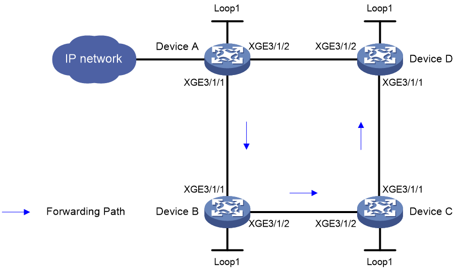
As shown in Figure 6, perform the following tasks on the devices to implement SR-MPLS TE policy-based forwarding:
· Configure Device A through Device D to run IS-IS to implement Layer 3 connectivity.
· Configure SR-MPLS on Device A through Device D to establish an SRLSP.
· Configure an SR-MPLS TE policy on Device A to forward user packets along path Device A > Device B > Device C > Device D.
|
Device |
Interface |
IP address |
Device |
Interface |
IP address |
|
Device A |
Loop1 |
1.1.1.1/32 |
Device B |
Loop1 |
2.2.2.2/32 |
|
|
XGE3/1/1 |
12.0.0.1/24 |
|
XGE3/1/1 |
12.0.0.2/24 |
|
|
XGE3/1/2 |
14.0.0.1/24 |
|
XGE3/1/2 |
23.0.0.2/24 |
|
Device C |
Loop1 |
3.3.3.3/32 |
Device D |
Loop1 |
4.4.4.4/32 |
|
|
XGE3/1/1 |
34.0.0.3/24 |
|
XGE3/1/1 |
34.0.0.4/24 |
|
|
XGE3/1/2 |
23.0.0.3/24 |
|
XGE3/1/2 |
14.0.0.4/24 |
Procedure
1. Configure IP addresses and masks for interfaces. (Details not shown.)
2. Configure Device A:
# Configure IS-IS and set the IS-IS cost style to wide.
<DeviceA> system-view
[DeviceA] isis 1
[DeviceA-isis-1] network-entity 00.0000.0000.0001.00
[DeviceA-isis-1] cost-style wide
[DeviceA-isis-1] quit
[DeviceA] interface ten-gigabitethernet 3/1/1
[DeviceA-Ten-GigabitEthernet3/1/1] isis enable 1
[DeviceA-Ten-GigabitEthernet3/1/1] quit
[DeviceA] interface ten-gigabitethernet 3/1/2
[DeviceA-Ten-GigabitEthernet3/1/2] isis enable 1
[DeviceA-Ten-GigabitEthernet3/1/2] quit
[DeviceA] interface loopback 1
[DeviceA-LoopBack1] isis enable 1
[DeviceA-LoopBack1] quit
# Configure the MPLS LSR ID, and enable MPLS and MPLS TE.
[DeviceA] mpls lsr-id 1.1.1.1
[DeviceA] mpls te
[DeviceA-te] quit
[DeviceA] interface ten-gigabitethernet 3/1/1
[DeviceA-Ten-GigabitEthernet3/1/1] mpls enable
[DeviceA-Ten-GigabitEthernet3/1/1] quit
[DeviceA] interface ten-gigabitethernet 3/1/2
[DeviceA-Ten-GigabitEthernet3/1/2] mpls enable
[DeviceA-Ten-GigabitEthernet3/1/2] quit
# Configure the SRGB and enable SR-MPLS in IPv4 unicast address family view.
[DeviceA] isis 1
[DeviceA-isis-1] segment-routing global-block 16000 16999
[DeviceA-isis-1] address-family ipv4
[DeviceA-isis-1-ipv4] segment-routing mpls
[DeviceA-isis-1-ipv4] quit
[DeviceA-isis-1] quit
# Configure the IS-IS prefix SID.
[DeviceA] interface loopback 1
[DeviceA-LoopBack1] isis prefix-sid index 10
[DeviceA-LoopBack1] quit
# Configure an SID list.
[DeviceA] segment-routing
[DeviceA-segment-routing] traffic-engineering
[DeviceA-sr-te] segment-list s1
[DeviceA-sr-te-sl-s1] index 10 mpls label 16020
[DeviceA-sr-te-sl-s1] index 20 mpls label 17030
[DeviceA-sr-te-sl-s1] index 30 mpls label 18040
[DeviceA-sr-te-sl-s1] quit
# Create an SR-MPLS TE policy and set the attributes.
[DeviceA-sr-te] policy p1
[DeviceA-sr-te-policy-p1] binding-sid mpls 15000
[DeviceA-sr-te-policy-p1] color 10 end-point ipv4 4.4.4.4
# Configure a candidate path for the SR-MPLS TE policy and specify an explicit path for the candidate path.
[DeviceA-sr-te-policy-p1] candidate-paths
[DeviceA-sr-te-policy-p1-path] preference 10
[DeviceA-sr-te-policy-p1-path-pref-10] explicit segment-list s1
[DeviceA-sr-te-policy-p1-path-pref-10] quit
[DeviceA-sr-te-policy-p1-path] quit
[DeviceA-sr-te-policy-p1] quit
[DeviceA-sr-te] quit
[DeviceA-segment-routing] quit
3. Configure Device B:
# Configure IS-IS and set the IS-IS cost style to wide.
<DeviceB> system-view
[DeviceB] isis 1
[DeviceB-isis-1] network-entity 00.0000.0000.0002.00
[DeviceB-isis-1] cost-style wide
[DeviceB-isis-1] quit
[DeviceB] interface ten-gigabitethernet 3/1/1
[DeviceB-Ten-GigabitEthernet3/1/1] isis enable 1
[DeviceB-Ten-GigabitEthernet3/1/1] quit
[DeviceB] interface ten-gigabitethernet 3/1/2
[DeviceB-Ten-GigabitEthernet3/1/2] isis enable 1
[DeviceB-Ten-GigabitEthernet3/1/2] quit
[DeviceB] interface loopback 1
[DeviceB-LoopBack1] isis enable 1
[DeviceB-LoopBack1] quit
# Configure the MPLS LSR ID, and enable MPLS and MPLS TE.
[DeviceB] mpls lsr-id 2.2.2.2
[DeviceB] mpls te
[DeviceB-te] quit
[DeviceB] interface ten-gigabitethernet 3/1/1
[DeviceB-Ten-GigabitEthernet3/1/1] mpls enable
[DeviceB-Ten-GigabitEthernet3/1/1] quit
[DeviceB] interface ten-gigabitethernet 3/1/2
[DeviceB-Ten-GigabitEthernet3/1/2] mpls enable
[DeviceB-Ten-GigabitEthernet3/1/2] quit
# Configure the SRGB and enable SR-MPLS in IPv4 unicast address family view.
[DeviceB] isis 1
[DeviceB-isis-1] segment-routing global-block 17000 17999
[DeviceB-isis-1] address-family ipv4
[DeviceB-isis-1-ipv4] segment-routing mpls
[DeviceB-isis-1-ipv4] quit
[DeviceB-isis-1] quit
# Configure the IS-IS prefix SID.
[DeviceB] interface loopback 1
[DeviceB-LoopBack1] isis prefix-sid index 20
[DeviceB-LoopBack1] quit
4. Configure Device C:
# Configure IS-IS and set the IS-IS cost style to wide.
<DeviceC> system-view
[DeviceC] isis 1
[DeviceC-isis-1] network-entity 00.0000.0000.0003.00
[DeviceC-isis-1] cost-style wide
[DeviceC-isis-1] quit
[DeviceC] interface ten-gigabitethernet 3/1/1
[DeviceC-Ten-GigabitEthernet3/1/1] isis enable 1
[DeviceC-Ten-GigabitEthernet3/1/1] quit
[DeviceC] interface ten-gigabitethernet 3/1/2
[DeviceC-Ten-GigabitEthernet3/1/2] isis enable 1
[DeviceC-Ten-GigabitEthernet3/1/2] quit
[DeviceC] interface loopback 1
[DeviceC-LoopBack1] isis enable 1
[DeviceC-LoopBack1] quit
# Configure the MPLS LSR ID, and enable MPLS and MPLS TE.
[DeviceC] mpls lsr-id 3.3.3.3
[DeviceC] mpls te
[DeviceC-te] quit
[DeviceC] interface ten-gigabitethernet 3/1/1
[DeviceC-Ten-GigabitEthernet3/1/1] mpls enable
[DeviceC-Ten-GigabitEthernet3/1/1] quit
[DeviceC] interface ten-gigabitethernet 3/1/2
[DeviceC-Ten-GigabitEthernet3/1/2] mpls enable
[DeviceC-Ten-GigabitEthernet3/1/2] quit
# Configure the SRGB and enable SR-MPLS in IPv4 unicast address family view.
[DeviceC] isis 1
[DeviceC-isis-1] segment-routing global-block 18000 18999
[DeviceC-isis-1] address-family ipv4
[DeviceC-isis-1-ipv4] segment-routing mpls
[DeviceC-isis-1-ipv4] quit
[DeviceC-isis-1] quit
# Configure the IS-IS prefix SID.
[DeviceC] interface loopback 1
[DeviceC-LoopBack1] isis prefix-sid index 30
[DeviceC-LoopBack1] quit
5. Configure Device D:
# Configure IS-IS and set the IS-IS cost style to wide.
<DeviceD> system-view
[DeviceD] isis 1
[DeviceD-isis-1] network-entity 00.0000.0000.0004.00
[DeviceD-isis-1] cost-style wide
[DeviceD-isis-1] quit
[DeviceD] interface ten-gigabitethernet 3/1/1
[DeviceD-Ten-GigabitEthernet3/1/1] isis enable 1
[DeviceD-Ten-GigabitEthernet3/1/1] quit
[DeviceD] interface ten-gigabitethernet 3/1/2
[DeviceD-Ten-GigabitEthernet3/1/2] isis enable 1
[DeviceD-Ten-GigabitEthernet3/1/2] quit
[DeviceD] interface loopback 1
[DeviceD-LoopBack1] isis enable 1
[DeviceD-LoopBack1] quit
# Configure the MPLS LSR ID, and enable MPLS and MPLS TE.
[DeviceD] mpls lsr-id 4.4.4.4
[DeviceD] mpls te
[DeviceD-te] quit
[DeviceD] interface ten-gigabitethernet 3/1/1
[DeviceD-Ten-GigabitEthernet3/1/1] mpls enable
[DeviceD-Ten-GigabitEthernet3/1/1] quit
[DeviceD] interface ten-gigabitethernet 3/1/2
[DeviceD-Ten-GigabitEthernet3/1/2] mpls enable
[DeviceD-Ten-GigabitEthernet3/1/2] quit
# Configure the SRGB and enable SR-MPLS in IPv4 unicast address family view.
[DeviceD] isis 1
[DeviceD-isis-1] segment-routing global-block 19000 19999
[DeviceD-isis-1] address-family ipv4
[DeviceD-isis-1-ipv4] segment-routing mpls
[DeviceD-isis-1-ipv4] quit
[DeviceD-isis-1] quit
# Configure the IS-IS prefix SID.
[DeviceD] interface loopback 1
[DeviceD-LoopBack1] isis prefix-sid index 40
[DeviceD-LoopBack1] quit
Verifying the configuration
# Display SR TE policy information on Device A.
[DeviceA] display segment-routing te policy
Name/ID: p1/0
Color: 10
Endpoint: 4.4.4.4
Name from Bgp:
BSID:
Mode: Explicit Type: Type_1 Request state: Succeeded
Current BSID: 15000 Explicit BSID: 15000 Dynamic BSID: -
Reference counts: 4
Flags: A/BS/NC
Status: Up
AdminStatus: Up
Up time: 2019-10-25 11:16:15
Down time: 2019-10-25 11:16:00
Hot-standby: Not configured
Statistics: Not configured
Statistics by service class: Not configured
SBFD: Not configured
BFD trigger path-down: Disabled
PolicyNid: 6201
Service-class: -
Candidate paths state: Configured
Candidate paths statistics:
CLI paths: 1 BGP paths: 0 PCEP paths: 0
Candidate paths:
Preference : 10
CPathName:
ProtoOrigin: CLI Discriminator: 10
Instance ID: 0 Node Address: 0.0.0.0
Originator: 0, 0.0.0.0
Optimal: Y Flags: V/A
Explicit SID list:
ID: 1 Name: s1
Weight: 1 Nid: 24117249
State: Up SBFD state: -
The output shows that the SR-MPLS TE policy is in up state. The device can use the SR-MPLS TE policy to forward packets.
# Display SR TE forwarding information on Device A.
[DeviceA] display segment-routing te forwarding verbose
Total Forwarding entries: 1
Policy name/ID: p1/0
Binding SID: 15000
Policy NID: 0x01400001
Main path:
SegList ID: 1
SegList NID: 0x01700001
Weight: 1
Outgoing NID: 0x01600001
OutLabels: 3
Interface: XGE3/1/1
NextHop: 12.0.0.2
Path ID: 0
Label stack: {17030, 18040}
The output shows that the label stack for packets forwarded by using the SR-MPLS TE policy is {17030, 18040}.
# Display MPLS LSP information on Device A.
[DeviceA] display mpls lsp
FEC Proto In/Out Label Out Inter/NHLFE/LSINDEX
12.0.0.2 Local -/- XGE3/1/1
14.0.0.4 Local -/- XGE3/1/2
1.1.1.1/32 ISIS 16010/- -
2.2.2.2/32 ISIS 16020/3 XGE3/1/1
2.2.2.2/32 ISIS -/3 XGE3/1/1
3.3.3.3/32 ISIS 16030/17030 XGE3/1/1
3.3.3.3/32 ISIS -/17030 XGE3/1/1
3.3.3.3/32 ISIS 16030/19030 XGE3/1/2
3.3.3.3/32 ISIS -/19030 XGE3/1/2
4.4.4.4/32 ISIS 16040/3 XGE3/1/2
4.4.4.4/32 ISIS -/3 XGE3/1/2
4.4.4.4/32/23068673 SRPolicy -/17030 XGE3/1/1
18040
24117249 SRPolicy -/- LSINDEX23068673
4.4.4.4/10 SRPolicy 15000/- LSINDEX24117249
The output shows that the forwarding paths used by the SR-MPLS TE policy.
