- Table of Contents
-
- 11-Segment Routing Configuration Guide
- 00-Preface
- 01-SR-MPLS configuration
- 02-SR-MPLS TE policy configuration
- 03-SRv6 configuration
- 04-SRv6 TE policy configuration
- 05-SRv6 VPN overview
- 06-IP L3VPN over SRv6 configuration
- 07-EVPN L3VPN over SRv6 configuration
- 08-EVPN VPWS over SRv6 configuration
- 09-EVPN VPLS over SRv6 configuration
- 10-Public network IP over SRv6 configuration
- 11-SRv6 OAM configuration
- 12-SRv6 network slicing configuration
- Related Documents
-
| Title | Size | Download |
|---|---|---|
| 09-EVPN VPLS over SRv6 configuration | 842.97 KB |
Configuring EVPN VPLS over SRv6
EVPN VPLS over SRv6 multihoming
LDP or static PW ACs for SRv6 PWs
Intercommunication between EVPN VPLS over SRv6 and EVPN VPWS over SRv6 networks
Restrictions and guidelines: EVPN VPLS over SRv6 configuration
EVPN VPLS over SRv6 tasks at a glance
About EVPN instance configuration
Restrictions and guidelines for EVPN instance configuration
Configuring an EVPN instance created in system view
Configuring an EVPN instance created in VSI view
Applying a locator to an EVPN instance
Applying a locator to an EVPN instance created in system view
Applying a locator to an EVPN instance created in VSI view
Configuring unicast traffic forwarding based on End.DX2 and End.DX2L SIDs
Configuring the route recursion mode
Prerequisites for route recursion mode configuration
Configuring the route recursion mode on an EVPN instance created in system view
Configuring the route recursion mode on an EVPN instance created in VSI view
Configuring SRv6 TE policy traffic steering
Restrictions and guidelines for SRv6 TE policy traffic steering
Configuring color-based traffic steering
Configuring tunnel policy-based traffic steering
Mapping a Layer 3 interface to a VSI
Mapping an Ethernet service instance to a VSI
Configuring PEs to exchange BGP EVPN routes
Specifying a source address for the outer IPv6 header of SRv6-encapsulated EVPN VPLS packets
Configuring EVPN VPLS over SRv6 multihoming
Restrictions and guidelines for EVPN VPLS over SRv6 multihoming
Configuring local FRR for EVPN VPLS over SRv6
Enabling VSIs to ignore the state of ACs
Enabling ARP flood suppression
Restrictions and guidelines for EVPN E-tree configuration
Configuring EVPN E-tree for an EVPN instance created in system view
Configuring EVPN E-tree for an EVPN instance created VSI view
Configuring LDP or static PWs as ACs for SRv6 PWs
About LDP or static PW AC configuration for SRv6 PWs
Restrictions and guidelines for LDP or static PW AC configuration for SRv6 PWs
Prerequisites for LDP or static PW AC configuration for SRv6 PWs
Configuring LDP PWs as ACs for SRv6 PWs
Configuring static PWs as ACs for SRv6 PWs
Configuring intercommunication between EVPN VPLS over SRv6 and EVPN VPWS over SRv6 networks
Configuring SRv6 PW packet statistics
Test the connectivity of an SRv6 PW
Using ping to test the connectivity of an SRv6 PW
Using tracert to test the connectivity of an SRv6 PW
Using a static BFD session to test the connectivity of an SRv6 PW
Display and maintenance commands for EVPN VPLS over SRv6
EVPN VPLS over SRv6 configuration examples
Example: Setting up an SRv6 tunnel between single-homed EVPN VPLS sites
Example: Configuring EVPN VPLS over SRv6 multihoming (S-Trunk dual-homed)
Example: Configuring LDP PWs as ACs for SRv6 PWs
Example: Configuring intercommunication between EVPN VPLS over SRv6 and EVPN VPWS over SRv6 networks
Configuring EVPN VPLS over SRv6
About EVPN VPLS over SRv6
EVPN VPLS over SRv6 uses SRv6 tunnels to carry EVPN VPLS services. This technology establishes point-to-multipoint connections for customer sites over the IPv6 backbone network and transparently forwards Layer 2 customer traffic over the IPv6 backbone network. For more information about EVPN VPLS configuration, see EVPN Configuration Guide.
Basic principle
As shown in Figure 1, PEs set up an SRv6 tunnel by advertising End.DT2M SIDs, End.DT2U SIDs, and End.DX2 SIDs to each other through BGP EVPN routes. On a PE, this SRv6 tunnel is used as a PW to encapsulate and forward Layer 2 data packets received from the local site and destined for a remote site. The devices on the IPv6 backbone transport network forward the SRv6-encapsulated packets according to the optimal routes calculated by an IGP. As a result, Layer 2 data packets of one customer site can be transparently forwarded to another site over the IPv6 backbone transport network.
Figure 1 EVPN VPLS over SRv6 network diagram
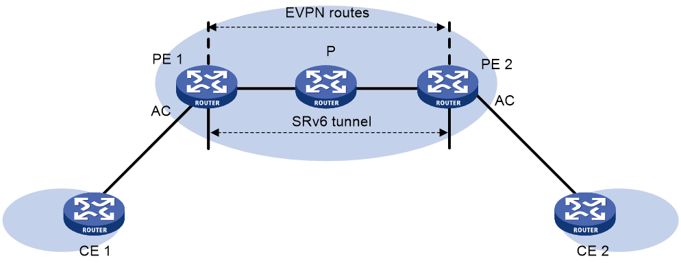
BGP EVPN route advertisement
A PE adds the End.DT2M SID and End.DT2U SID of a local VSI or the End.DX2 SID of an AC to BGP EVPN routes and advertises the routes to remote PEs. The routes help the PE establish an SRv6 tunnel to each remote PE.
· The End.DT2M SID is carried in Ethernet auto-discovery routes or IMET routes and is used to deliver EVPN VPLS broadcast, unknown unicast, and multicast (BUM) traffic.
· The End.DT2U or End.DX2 SID is carried in MAC/IP advertisement routes and is used to deliver EVPN VPLS known unicast traffic.
A pair of PEs both advertise End.DT2M SIDs and End.DT2U or End.DX2 SIDs, and they establish two SRv6 tunnels at two directions. The two SRv6 tunnels form a PW to carry Layer 2 customer traffic.
Traffic forwarding
EVPN VPLS over SRv6 supports the following route recursion modes:
· SRv6 BE mode.
· SRv6 TE mode.
· SRv6 TE and SRv6 BE hybrid mode.
The packet forwarding process differs by the route recursion mode in use.
SRv6 BE mode
This mode is also called SID-based forwarding mode. In this mode, a PE forwards an SRv6 packet by searching the IPv6 routing table based on the End.DT2U, End.DX2, or End.DT2M SID encapsulated in the packet.
As shown in Figure 1, a Layer 2 known unicast packet is forwarded from CE 1 to CE 2 as follows:
1. CE 1 sends the Layer 2 packet to PE 1.
2. After PE 1 receives the packet on the AC connected to CE 1, it searches the MAC address table of the VSI associated with that AC for the destination MAC address. PE 1 finds that the output interface is an SRv6 tunnel and obtains the End.DT2U or End.DX2 SID of the SRv6 tunnel.
3. PE 1 encapsulates an outer IPv6 header for the packet. The End.DT2U or End.DX2 SID is encapsulated in the outer IPv6 header as the destination IPv6 address. The source IPv6 address is the source address specified for the outer IPv6 header of SRv6-encapsulated EVPN VPLS packets.
4. PE 1 searches the IPv6 routing table based on the End.DT2U or End.DX2 SID for the optimal IGP route and forwards the packet to P through the optimal IGP route.
5. P searches the IPv6 routing table based on the End.DT2U or End.DX2 SID for the optimal IGP route and forwards the packet to PE 2 through the optimal IGP route.
6. PE 2 searches the local SID forwarding table for the End.DT2U or End.DX2 SID. According to the SID type, PE 2 removes the outer IPv6 header from the packet and performs the following operations:
¡ If the SID is an End.DT2U SID, PE 2 matches the packet to a VSI and searches the MAC address table of the VSI for the destination MAC address. Then, PE 2 forwards the packet to CE 2.
¡ If the SID is an End.DX2 SID, PE 2 forwards the packet to the AC associated with the End.DX2 SID.
As shown in Figure 1, a Layer 2 broadcast, multicast, or unknown unicast packet is forwarded as follows:
1. CE 1 sends the Layer 2 packet to PE 1.
2. After PE 1 receives the packet on the AC connected to CE 1, it searches all End.DT2M SIDs received from remote PEs on the VSI associated with the AC.
3. PE 1 encapsulates an outer IPv6 header for the packet. An End.DT2M SID is encapsulated in the outer IPv6 header as the destination IPv6 address. The source IPv6 address is the source address specified for the outer IPv6 header of SRv6-encapsulated EVPN VPLS packets.
If PE 1 has received End.DT2M SIDs from multiple remote PEs, it encapsulates each End.DT2M SID to the Layer 2 packet and floods the packet to all remote PEs.
4. PE 1 searches the IPv6 routing table based on the End.DT2M SID for the optimal IGP route and forwards the packet to P through the optimal IGP route.
5. P searches the IPv6 routing table based on the End.DT2M SID for the optimal IGP route and forwards the packet to PE 2 through the optimal IGP route.
6. PE 2 searches the local SID forwarding table for the End.DT2M SID and performs the following operations:
a. Removes the outer IPv6 header.
b. Matches the packet to a VSI based on the End.DT2M SID.
c. Floods the packet in the VSI.
SRv6 TE mode
This mode is also called SRv6 TE policy-based forwarding mode. In this mode, when the PE forwards a customer packet, it first searches for a matching SRv6 TE policy based on the packet attributes. Then, the PE adds an SRH to the packet. The SRH includes the destination End.DT2M SID or End.DT2U or End.DX2 SID and the SID list of the SRv6 TE policy. Finally, the PE forwards the encapsulated packet based on the SRv6 TE policy.
The following modes are available to steer traffic to an SRv6 TE policy:
· Color—The device searches for an SRv6 TE policy that has the same color and endpoint address as the color and nexthop address of a BGP EVPN route. If a matching SRv6 TE policy exists, the device recurses the BGP EVPN route to that SRv6 TE policy. When the device receives packets that match the BGP EVPN route, it forwards the packets through the SRv6 TE policy.
· Tunnel policy—The device searches the tunnel policies for a matching SRv6 TE policy based on the next hop of a matching route. Configure a preferred tunnel or load sharing tunnel policy that uses the SRv6 TE policy. In this way, the SRv6 TE policy will be used as the public tunnel to carry the SRv6 PW that forwards the packets of private network packets.
For more information about tunnel policies, see MPLS Configuration Guide. For more information about SRv6 TE policies, see "Configuring SRv6 TE policies."
SRv6 TE and SRv6 BE hybrid mode
In this mode, the PE preferentially uses the SRv6 TE mode to forward a customer packet. If no SRv6 TE policy is available for the packet, the PE forwards the packet in SRv6 BE mode.
EVPN VPLS over SRv6 multihoming
About EVPN VPLS over SRv6 multihoming
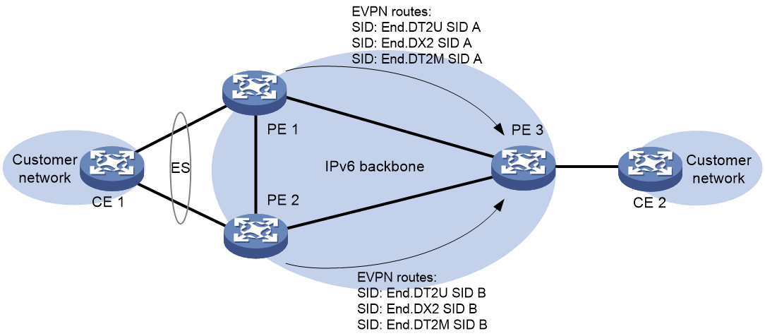
As shown in Figure 2, EVPN VPLS over SRv6 supports deploying multiple PEs at a site for redundancy and high availability. On the redundant PEs, Ethernet links connected to the site form an Ethernet segment (ES) that is uniquely identified by an ES identifier (ESI). EVPN VPLS over SRv6 supports only dualhoming.
Figure 2 EVPN VPLS over SRv6 multihoming
Redundancy mode
The device supports single-active redundancy mode and all-active redundancy mode of EVPN VPLS over SRv6 multihoming.
· All-active mode—This mode allows all redundant PEs to a multihomed site to load share unicast traffic.
· Single-active mode—This mode allows one of the redundant PEs to forward traffic. When the primary PE becomes unavailable because of device failure or link failure, traffic is switched to the backup PE for forwarding. A designated forwarder (DF) is elected from the redundant PEs as the primary PE. For more information about DF election, see EVPN VPLS configuration in EVPN Configuration Guide.
Route advertisement
The redundant PEs at a multihomed site both advertise End.DT2U or End.DX2 SIDs and End.DT2M SIDs to remote PEs. In addition, they advertise the redundancy mode of the multihomed site and their roles (primary or secondary) to remote PEs. A remote PE handles BGP EVPN routes advertised by the redundant PEs based on the redundancy mode.
· In all-active mode, the remote PE treats the routes advertised by the redundant PEs as ECMP routes that can load share traffic.
· In single-active mode, the remote PE treats the routes advertised by the primary PE as the optimal routes and only uses the optimal routes to forward traffic.
Local FRR for EVPN VPLS over SRv6
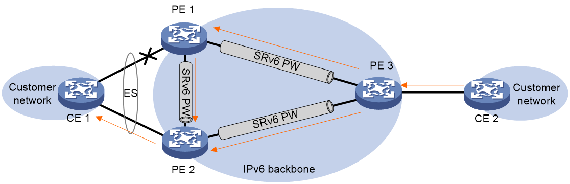
As shown in Figure 3, CE 1 is dualhomed to PE 1 and PE 2, and PE 1 is the DF. When the AC on PE 1 fails, PE 1 deletes the corresponding MAC address entries and advertises the local unreachable event to PE 2 and remote PEs (PE 3 in this example). Then, the remote PEs will switch traffic destined for CE 1 to the tunnels to PE 2. This process takes some time. PE 1 might receive packets destined for CE 1 before the remote PEs are notified of the unreachable event and perform link switchover. In this situation, PE 1 drops the packets, because the AC's MAC address entries have been deleted. To resolve this issue, enable local FRR on PE 1. If an AC fails, PE 1 changes the output interface of the AC's MAC address entries to the index of the bypass SRv6 PW between PE 1 and PE 2. When receiving packets from remote PEs after its AC fails, PE 1 forwards the packets to PE 2 over the bypass SRv6 PW to prevent traffic loss.
Figure 3 Local FRR network diagram
A loop might exist if PE 1 and PE 2 establish a bypass SRv6 PW between them through End.DT2U or End.DX2 SIDs. When the AC on PE 1 or PE 2 fails, PE 1 or PE 2 forwards the packets received from its peer back to its peer through the bypass SRv6 PW. To resolve this issue, use End.DT2UL or End.DX2L SIDs to establish a bypass SRv6 PW between PE 1 and PE 2. The packets from a bypass SRv6 PW carry an End.DT2UL or End.DX2L SID. A PE does not forward the packets back to the bypass SRv6 PW.
PEs preferentially use End.DT2UL or End.DX2L SIDs to establish a bypass SRv6 PW. If no End.DT2UL or End.DX2L SIDs are available, the PEs use End.DT2U or End.DX2 SIDs to establish a bypass SRv6 PW.
EVPN E-tree
About EVPN E-tree
In an EVPN VPLS over SRv6 network, EVPN E-tree isolates unicast and flood traffic (broadcast, multicast, and unknown unicast) of ACs in the same EVPN instance based on the AC roles. With EVPN E-tree, the device isolates unicast and flood traffic of ACs in the same EVPN instance as follows:
· Leaf ACs can access root ACs.
· Leaf ACs cannot access each other.
· Root ACs can access each other and access leaf ACs.
Figure 4 EVPN E-tree network diagram
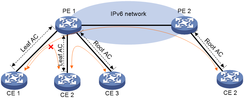
Local traffic isolation
EVPN E-tree isolates traffic between local ACs on a PE as follows:
· When the PE receives packets from a leaf AC on a VSI, it forwards the packets only to root ACs on the VSI.
· When the PE receives packets from a root AC on a VSI, it forwards the packets to all local ACs on the VSI except the incoming AC.
Remote known unicast traffic isolation
With EVPN E-tree, PEs perform MAC address learning for hosts attached to leaf ACs as follows:
1. When a PE receives a packet from a leaf AC, it learns the source MAC address of the packet and adds the Leaf flag to the MAC address.
2. The PE advertises the MAC address to the remote PE in a MAC/IP advertisement route. The route carries the E-tree extended community attribute that contains the Leaf flag.
3. The remote PE adds the MAC address that carries the Leaf flag to the MAC address table.
When one PE receives a packet destined for a host on another PE from a local AC, it searches the MAC address table for the destination MAC address. If the entry of the destination MAC address has the Leaf flag and the packet is also from a leaf AC, the PE discards the packet. In other situations, the PE forwards the packet.
Remote flood traffic isolation
With EVPN E-tree, a PE sets the Args value of SRv6 SIDs to 1 for leaf ACs. The PE adds the Args value to Ethernet auto-discovery routes and advertises the routes to remote PEs.
EVPN E-tree isolates flood traffic from one PE to another PE as follows:
1. When a PE receives a flood packet from a leaf AC on a VSI, it recalculates the End.DT2M SID based on the End.DT2M SID advertised by the remote PE and the Args value of 1. Then, the local PE adds the newly calculated End.DT2M SID to the packet and forwards the packet to the remote PE.
2. The remote PE checks the Args value of the End.DT2M SID and finds that the value is 1. Then, the PE forwards the packet only to local root ACs on the same VSI.
If a PE receives a flood packet from a root AC, it directly adds the End.DT2M SID advertised by the remote PE to the packet and forwards the packet to the remote PE. The Args value of the End.DT2M SID is 0 by default. When the remote PE receives the packet, it forwards the packet to both local root ACs and local leaf ACs.
LDP or static PW ACs for SRv6 PWs
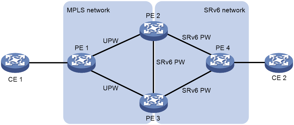
This feature ensures that a traditional MPLS VPLS network and an EVPN VPLS over SRv6 network can communicate with each other. The LDP or static PWs in the VPLS network are configured as ACs to the SRv6 PWs in the SRv6 network. These ACs are referred to as UPWs in the EVPN VPLS over SRv6 network. Packets can be forwarded between SRv6 PWs and UPWs, so the VPLS and EVPN VPLS over SRv6 networks can communicate with each other.
With this feature, an LDP or static PW can be single-homed to an SRv6 PW or two LDP or static PWs can be dual-homed to two SRv6 PWs.
As shown in Figure 5, in the VPLS network, PE 1 is connected to PE 2 and PE 3 through LDP or static PWs. One of the PWs is the primary PW and the other PW is the backup PW. The PWs are UPWs. In the EVPN VPLS over SRv6 network, PE 4 is connected to PE 2 and PE 3 through SRv6 PWs. The UPWs in the VPLS network act as ACs for the SRv6 network. When PE 2 or PE 3 receives packets from an UPW, it decapsulates MPLS encapsulation from the packets and looks up the MAC address table for a matching SRv6 PW. Then, the PE adds SRv6 encapsulation to the packets and forwards the packets to PE 4. When PE 2 or PE 3 receives packets from an SRv6 PW, it uses the same procedure to process the packets.
Figure 5 Using LDP or static PWs as ACs for SRv6 PWs
Intercommunication between EVPN VPLS over SRv6 and EVPN VPWS over SRv6 networks
In an EVPN VPWS over SRv6 network, an SRv6 PW can be associated only with one AC. If multiple ACs are attached to a PE, the PE cannot use the same SRv6 PW to forward traffic for the ACs. For the PE to use the same SRv6 PW to forward traffic for the ACs in the EVPN VPWS over SRv6 network, configure intercommunication between EVPN VPLS over SRv6 and EVPN VPWS over SRv6 networks. With this feature, you can associate an SRv6 PW with multiple ACs on the PE without changing existing SRv6 PW and AC associations in the EVPN VPWS over SRv6 network. The PE where an SRv6 PW is associated with multiple ACs acts as a boundary PE between the EVPN VPWS over SRv6 and EVPN VPLS over SRv6 networks.
|
|
IMPORTANT: In the current software version, for intercommunication between an EVPN VPLS over SRv6 network and an EVPN VPWS over SRv6 network, a maximum of two boundary PEs can be deployed to connect the networks. In the EVPN VPWS over SRv6 network, a maximum of two PEs can be deployed in addition to the boundary PEs. The EVPN VPLS over SRv6 network cannot have any PEs other than the boundary PEs. |
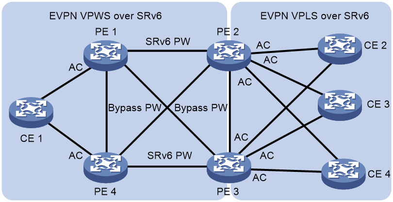
As shown in Figure 6, boundary PEs (PE 2 and PE 3) each assigns an End.DT2U SID to a VSI and uses Ethernet auto-discovery routes to advertise the SIDs to the PEs (PE 1 and PE 4) in the EVPN VPWS over SRv6 network. PE 1 and PE 4 use the standard process to allocate and advertise End.DX2 SIDs. After the PEs receive SRv6 SIDs from the peers, each pair of the PEs establish an SRv6 PW.
After SRv6 PWs are established, a packet is forwarded from the EVPN VPWS over SRv6 network to the EVPN VPLS over SRv6 network as follows:
1. When PE 1 receives the packet from CE 1, it performs the following operations:
a. Looks up for the SRv6 PW associated with the AC that receives the packet.
b. Adds the SRv6 SID of the PW to the packet. The SRv6 SID is the End.DT2U SID allocated by PE 2 or PE 3.
c. Forwards the packet to PE 2 or PE 3.
2. When PE 2 or PE 3 receives the packet from the SRv6 PW, it performs the following operations:
a. Decapsulates the packet.
b. Handles the packet according to the function of the SRv6 SID, that is, looks up the MAC address table to forward the packet to the matching AC. If no matching AC is found, PE 2 or PE 3 broadcasts the packet to all ACs in the VSI.
|
|
NOTE: The PEs (PE 1 and PE 4) in the EVPN VPWS over SRv6 network can be multihomed to the boundary PEs. In this case, you must specify an ESI and multihoming redundancy mode in VSI view on the boundary PEs. PE 1 or PE 4 forwards packets to PE 2 or PE 3 when it receives the packets from an AC, depending on the multihoming redundancy mode and the roles (DF or not) of PE 2 and PE 3. |
A packet is forwarded from the EVPN VPLS over SRv6 network to the EVPN VPWS over SRv6 network as follows:
1. When PE 2 receives the packet from CE 2, it performs the following operations:
a. Looks up for a matching SRv6 PW in the VSI mapped to the AC that receives the packet.
b. Adds the SRv6 SID of the SRv6 PW to the packet. The SRv6 SID is the End.DX2 SID allocated by PE 1 or PE 4.
c. Forwards the packet to PE 1 or PE 4.
2. When PE 1 or PE 4 receives the packet from the SRv6 PW, it decapsulates the packet and forwards the packet to the AC associated with the End.DX2 SID.
|
|
NOTE: · In the EVPN VPWS over SRv6 network, if a CE (CE 1 in Figure 6) is multihomed to the PEs (PE 1 and PE 4), you must specify an ESI and multihoming redundancy mode on the interfaces connected to the CE on PE 1 and PE 4. A boundary PE forwards packets received from ACs to PE 1 or PE 4, depending on the multihoming redundancy mode and the roles (DF or not) of PE 1 and PE 4. · When a boundary PE receives packets from ACs in the EVPN VPLS over SRv6 network, it forwards all of the packets to SRv6 PWs. ACs in the EVPN VPLS over SRv6 network cannot communicate with each other. |
Restrictions and guidelines: EVPN VPLS over SRv6 configuration
In standard system operating mode, only the following cards support this feature:
|
Card category |
Cards |
|
CEPC |
CEPC-CQ8L, CEPC-CQ8LA, CEPC-CQ8L1A, CEPC-CQ16L1 |
|
CSPEX |
CSPEX-1802X, CSPEX-1802XA, CSPEX-2612XA, CSPEX-1812X-E, CSPEX-2304X-G, CSPEX-1502XA |
|
SPE |
RX-SPE200-E |
In SDN-WAN system operating mode, only the following cards support this feature:
|
Card category |
Cards |
|
CEPC |
CEPC-XP4LX, CEPC-XP24LX, CEPC-XP48RX, CEPC-CP4RX, CEPC-CP4RXA, CEPC-CP4RX-L, CEPC-CQ8L, CEPC-CQ8LA, CEPC-CQ8L1A, CEPC-CQ16L1 |
|
CSPEX |
CSPEX-1304X, CSPEX-1404X, CSPEX-1502X, CSPEX-1504X, CSPEX-1504XA, CSPEX-1602X, CSPEX-1602XA, CSPEX-1804X, CSPEX-1512X, CSPEX-1612X, CSPEX-1812X, CSPEX-1802X, CSPEX-1802XA, CSPEX-2612XA, CSPEX-1812X-E, CSPEX-2304X-G, CSPEX-1502XA |
|
SPE |
RX-SPE200, RX-SPE200-E |
|
OAA |
IM-NGFWX-IV |
EVPN VPLS over SRv6 networks do not support using BFD to verify PW connectivity.
EVPN VPLS over SRv6 networks do not support ARP suppression.
If an MPLS L2VPN network is used to access an L3VPN or IP backbone, do not configure the MPLS L2VPN network as an EVPN VPLS over SRv6 network.
The E-tree feature is not supported in a network configured with CFD and NQA. For more information about CFD, see High Availability Configuration Guide. For more information about NQA, see Network Management and Monitoring Configuration Guide.
EVPN VPLS over SRv6 tasks at a glance
To configure EVPN VPLS over SRv6, perform the following tasks:
1. Creating and configuring an EVPN instance
b. Configuring an EVPN instance
2. Applying for SRv6 SIDs from a locator
b. Applying a locator to an EVPN instance
3. Configuring packet forwarding methods
¡ (Optional.) Configuring unicast traffic forwarding based on End.DX2 and End.DX2L SIDs
¡ Configuring the route recursion mode
¡ Configuring SRv6 TE policy traffic steering
This task is required if the route recursion mode is SRv6 TE mode or SRv6 TE and SRv6 BE hybrid mode.
5. Configuring PEs to exchange BGP EVPN routes
6. Configure SRv6 packets
¡ Specifying a source address for the outer IPv6 header of SRv6-encapsulated EVPN VPLS packets
7. (Optional.) Configuring EVPN VPLS over SRv6 multihoming
8. (Optional.) Configuring advanced features for EVPN VPLS over SRv6
¡ Enabling ARP flood suppression
¡ Configuring LDP or static PWs as ACs for SRv6 PWs
¡ Configuring intercommunication between EVPN VPLS over SRv6 and EVPN VPWS over SRv6 networks
9. (Optional.) Maintaining the EVPN VPLS over SRv6 network
¡ Configuring SRv6 PW packet statistics
¡ Test the connectivity of an SRv6 PW
Creating a VSI
Restrictions and guidelines
For more information about the commands in this section, see VPLS commands in MPLS Command Reference.
Procedure
1. Enter system view.
system-view
2. Enable L2VPN.
l2vpn enable
By default, L2VPN is disabled.
3. Create a VSI and enter VSI view.
vsi vsi-name
4. Bring up the VSI.
undo shutdown
By default, a VSI is not administratively down.
Configuring an EVPN instance
About EVPN instance configuration
The BGP EVPN routes advertised by a PE carry the RD and route targets configured for the EVPN instance of the routes.
Use one of the following methods to create an EVPN instance:
· Create an EVPN instance in system view—You can bind an EVPN instance created in system view to multiple VSIs to simplify configuration.
· Create an EVPN instance on a VSI—An EVPN instance created in VSI view is automatically bound with the VSI.
Restrictions and guidelines for EVPN instance configuration
If you have created an EVPN instance in VSI view for a VSI, you cannot bind the VSI to an EVPN instance created in system view. If you have bound a VSI to an EVPN instance created in system view, you cannot create an EVPN instance in VSI view for the VSI.
Configuring an EVPN instance created in system view
1. Enter system view.
system-view
2. (Optional.) Configure a PW class.
a. Create a PW class and enter its view.
pw-class class-name
For more information about this command, see MPLS Command Reference.
b. Configure the SRv6 PW data encapsulation type for the PW class.
srv6-pw-type { ethernet | vlan }
By default, the SRv6 PW data encapsulation type for the PW class is Ethernet.
c. Return to system view.
quit
3. Create an EVPN instance and enter its view.
evpn instance instance-name
For more information about this command, see EVPN Command Reference.
4. Configure an RD for the EVPN instance.
route-distinguisher route-distinguisher
By default, no RD is configured for an EVPN instance.
For more information about this command, see EVPN Command Reference.
5. Configure route targets for the EVPN instance.
vpn-target vpn-target&<1-8> [ both | export-extcommunity | import-extcommunity ]
By default, an EVPN instance does not have route targets.
For more information about this command, see EVPN Command Reference.
|
Parameter |
Description |
|
export-extcommunity |
Do not specify the same export targets for different EVPN instances. Do not specify the same export targets for the EVPN instances created in different views (system view, VSI view, VPN instance view, public instance view, and cross-connect group view). As a best practice, the export targets configured for the following objects do not match the import targets configured for the EVPN instances created in cross-connect group view: · VPN instances. · The public instance. · EVPN instances created in system view, VSI view, VPN instance view, and public instance view. |
|
import-extcommunity |
As a best practice, the import targets configured for the following objects do not match the export targets configured for the EVPN instances created in cross-connect group view: · VPN instances. · The public instance. · EVPN instances created in system view, VSI view, VPN instance view, and public instance view. |
6. (Optional.) Apply a PW class to the EVPN instance.
pw-class class-name
By default, no PW class is applied to an EVPN instance.
The PW class applies to all PWs created for the EVPN instance.
For more information about this command, see EVPN Command Reference.
7. (Optional.) Apply a tunnel policy to the EVPN instance.
tunnel-policy tunnel-policy-name
By default, no tunnel policy is applied to an EVPN instance.
For more information about this command, see EVPN Command Reference.
8. (Optional.) Apply an export routing policy to the EVPN instance.
export route-policy route-policy
By default, no export routing policy is applied to a VPN instance.
For more information about this command, see EVPN Command Reference.
9. (Optional.) Apply an import routing policy to the VPN instance.
import route-policy route-policy
By default, no import routing policy is applied to a VPN instance. The VPN instance accepts a route when the export route targets of the route match local import route targets.
For more information about this command, see EVPN Command Reference.
10. Return to system view.
quit
11. Enter VSI view.
vsi vsi-name
For more information about this command, see EVPN Command Reference.
12. Bind the VSI to the EVPN instance.
evpn encapsulation srv6 binding instance instance-name vsi-tag tag-id
By default, a VSI is not bound to an EVPN instance created in system view.
You can bind a VSI only to one EVPN instance that uses SRv6 encapsulation.
Configuring an EVPN instance created in VSI view
1. Enter system view.
system-view
2. (Optional.) Configure a PW class.
a. Create a PW class and enter its view.
pw-class class-name
For more information about this command, see MPLS Command Reference.
b. Configure the SRv6 PW data encapsulation type for the PW class.
srv6-pw-type { ethernet | vlan }
By default, the SRv6 PW data encapsulation type for the PW class is Ethernet.
c. Return to system view.
quit
3. Enter VSI view.
vsi vsi-name
For more information about this command, see EVPN Command Reference.
4. Create an EVPN instance and enter VSI EVPN instance view.
evpn encapsulation srv6
5. Configure an RD for the EVPN instance.
route-distinguisher route-distinguisher
By default, no RD is configured for an EVPN instance.
For more information about this command, see EVPN Command Reference.
6. Configure route targets for the EVPN instance.
vpn-target { vpn-target&<1-8> } [ both | export-extcommunity | import-extcommunity ]
By default, an EVPN instance does not have route targets.
For more information about this command, see EVPN Command Reference.
|
Parameter |
Description |
|
export-extcommunity |
Do not specify the same export targets for the EVPN instances of different VSIs. Do not specify the same export targets for the EVPN instances created in different views (system view, VSI view, VPN instance view, public instance view, and cross-connect group view). As a best practice, the export targets configured for the following objects do not match the import targets configured for the EVPN instances created in cross-connect group view: · VPN instances. · The public instance. · EVPN instances created in system view, VSI view, VPN instance view, and public instance view. |
|
import-extcommunity |
As a best practice, the import targets configured for the following objects do not match the export targets configured for the EVPN instances created in cross-connect group view: · VPN instances. · The public instance. · EVPN instances created in system view, VSI view, VPN instance view, and public instance view. |
7. (Optional.) Apply a PW class to the EVPN instance.
pw-class class-name
By default, no PW class is applied to an EVPN instance.
The PW class applies to all PWs in the EVPN instance.
For more information about this command, see EVPN Command Reference.
8. (Optional.) Apply a tunnel policy to the EVPN instance.
tunnel-policy tunnel-policy-name
By default, no tunnel policy is applied to an EVPN instance.
For more information about this command, see EVPN Command Reference.
Configuring SRv6 SIDs
1. Enter system view.
system-view
2. Enable SRv6 and enter SRv6 view.
segment-routing ipv6
3. Configure a locator and enter SRv6 locator view.
locator locator-name [ ipv6-prefix ipv6-address prefix-length [ args args-length | static static-length ] * ]
4. Configure the opcode portion.
¡ Configure End.DT2U SIDs.
opcode { opcode | hex hex-opcode } end-dt2u vsi vsi-name
¡ Configure End.DT2UL SIDs.
opcode { opcode | hex hex-opcode } end-dt2ul vsi vsi-name
¡ Configure End.DX2 SIDs.
opcode { opcode | hex hex-opcode } end-dx2 vsi vsi-name interface interface-type interface-number [ service-instance instance-id ]
¡ Configure End.DX2L SIDs.
opcode { opcode | hex hex-opcode } end-dx2l vsi vsi-name interface interface-type interface-number [ service-instance instance-id ]
¡ Configure End.DT2M SIDs.
opcode { opcode | hex hex-opcode } end-dt2m vsi vsi-name
Applying a locator to an EVPN instance
About this task
Perform this task to allocate SRv6 SIDs from a locator to the VSIs bound to an EVPN instance.
Use one of the following methods to apply a locator to an EVPN instance:
· Apply a locator to an EVPN instance created in system view—The locator will be applied to all VSIs bound to that EVPN instance to simplify configuration.
· Apply a locator to the EVPN instance created on a VSI—You can apply the same locator to multiple VSIs.
Applying a locator to an EVPN instance created in system view
1. Enter system view.
system-view
2. Create an EVPN instance and enter EVPN instance view.
evpn instance instance-name
3. Apply a locator to the EVPN instance.
segment-routing ipv6 locator locator-name [ dt2u-locator dt2u-locator-name ] [ dt2ul-locator dt2ul-locator-name ] [ auto-sid-disable ]
By default, no locator is applied to an EVPN instance created in system view.
Applying a locator to an EVPN instance created in VSI view
1. Enter system view.
system-view
2. Enter VSI view.
vsi vsi-name
3. Enter VSI EVPN instance view.
evpn encapsulation srv6
4. Apply a locator to the EVPN instance.
segment-routing ipv6 locator locator-name [ dt2u-locator dt2u-locator-name ] [ dt2ul-locator dt2ul-locator-name ] [ dx2-locator dx2-locator-name ] [ dx2l-locator dx2l-locator-name ] [ auto-sid-disable ]
By default, no locator is applied to the EVPN instance on a VSI.
Configuring unicast traffic forwarding based on End.DX2 and End.DX2L SIDs
About this task
By default, when a PE receives a packet that includes an End.DT2U or End.DT2UL SID, it looks up the MAC address table of the SID's VSI to forward the packet.
To improve forwarding efficiency, use this feature. This feature enables the PE to allocate an End.DX2 or End.DX2L SID to each AC associated with a VSI and advertise the SIDs to remote PEs through MAC/IP advertisement routes. When the PE receives an SRv6 packet that includes a locally allocated End.DX2 or End.DX2L SID, it does not look up the MAC address table. The PE directly forwards the packet to the AC that is associated with the SID after removing the SRv6 encapsulation.
Restrictions and guidelines
The unicast-forwarding dx2-based and unknown-mac-route commands are mutually exclusive. If you use both the commands, the device cannot correctly advertise UMRs.
Procedure
1. Enter system view.
system-view
2. Enter VSI view.
vsi vsi-name
3. Enter VSI EVPN instance view.
evpn encapsulation srv6
4. Configure unicast traffic forwarding based on End.DX2 and End.DX2L SIDs.
unicast-forwarding dx2-based
By default, unicast traffic is forwarded based on End.DT2U and End.DT2UL SIDs.
Configuring the route recursion mode
About route recursion modes
After a PE receives a customer packet destined for an End.DT2M, End.DT2U, End.DT2UL, End.DX2, or End.DX2L SID, it forwards the packet according to the route recursion mode.
· SRv6 BE mode—In this mode, the PE first encapsulates the SID into the packet. Then, the PE searches the IPv6 routing table based on the SID encapsulated in the packet to forward the packet.
· SRv6 TE mode—In this mode, the PE first searches for a matching SRv6 TE policy based on the color attribute or next hop address of a matching route. Then, the PE adds an SRH to the packet. The SRH includes the End.DT2M, End.DT2U, End.DT2UL, End.DX2, or End.DX2L SID and the SID list of the SRv6 TE policy. Finally, the PE forwards the encapsulated packet through the SRv6 TE policy. For more information, see "Configuring SRv6 TE policies."
· SRv6 TE and SRv6 BE hybrid mode—In this mode, the PE preferentially uses the SRv6 TE mode to forward the packet. If no SRv6 TE policy is available for the packet, the PE forwards the packet in SRv6 BE mode.
In SRv6 TE mode, you can associate the SRv6 TE policy that contains paths between two PEs with the static BFD session specified for testing the IP connectivity between the two PEs. For this purpose, you must execute the segment-routing ipv6 traffic-engineer command with the track-bfd keyword and create a static BFD session to test the IP connectivity between the two PEs. If the static BFD session goes down, the state of the SRv6 TE policy also changes to down. This mechanism avoids traffic forwarding failure caused by path disconnectivity. For more information about static BFD, see High Availability Configuration Guide. For more information about testing the IP connectivity between two PEs, see "Using a static BFD session to test the connectivity of an SRv6 PW."
Prerequisites for route recursion mode configuration
To use the SRv6 TE mode or the SRv6 TE and SRv6 BE hybrid mode, you must configure SRv6 TE policy traffic steering. For more information, see "Configuring SRv6 TE policy traffic steering."
Configuring the route recursion mode on an EVPN instance created in system view
1. Enter system view.
system-view
2. Create an EVPN instance and enter EVPN instance view.
evpn instance instance-name
3. Configure the route recursion mode.
segment-routing ipv6 { best-effort | traffic-engineering [ best-effort ] }
By default, a PE searches the IPv6 routing table based on the next hop of a matching EVPN route to forward traffic.
If a VSI is bound to the EVPN instance, the VSI will use the route recursion mode specified for the EVPN instance.
Configuring the route recursion mode on an EVPN instance created in VSI view
1. Enter system view.
system-view
2. Enter VSI view.
vsi vsi-name
3. Enter VSI EVPN instance view.
evpn encapsulation srv6
4. Configure the route recursion mode.
segment-routing ipv6 { best-effort | traffic-engineering [ track-bfd ] [ best-effort ] }
By default, a PE searches the IPv6 routing table based on the next hop of a matching EVPN route to forward traffic.
Configuring SRv6 TE policy traffic steering
Restrictions and guidelines for SRv6 TE policy traffic steering
This task is required if the route recursion mode is SRv6 TE mode or SRv6 TE and SRv6 BE hybrid mode.
If both color-based traffic steering and tunnel policy-based traffic steering are configured, the device selects a traffic steering method in the following order for a tunnel:
1. The policy bound to the tunnel.
2. Color-based traffic steering. If the device fails to use this method, the load sharing policy for tunnels is used.
3. Preferred tunnel policy. This method does not take effect if color-based traffic steering is configured.
4. Load sharing policy for tunnels. If no load sharing policy is configured, the default tunnel policy is used.
Configuring color-based traffic steering
About this task
The device searches for an SRv6 TE policy that has the same color and endpoint address as the color and next hop address of a BGP EVPN route. If a matching SRv6 TE policy exists, the device recurses the route to that SRv6 TE policy. When the device receives packets that match the route, it forwards the packets through the SRv6 TE policy.
Use one of the following methods to configure colors for BGP EVPN routes:
· Routing policy-based coloring—Configure a routing policy to add the color extended community attribute to BGP EVPN routes or modify the existing color extended community attribute in BGP EVPN routes.
· Default color—Specify a color as the default color for BGP EVPN routes. A BGP EVPN route uses the default color for color-based traffic steering if the route does not have the color extended community attribute or match a routing policy to obtain a color.
Restrictions and guidelines
Traffic steering is based on the greatest value among the color extended community attributes when the following conditions exist:
· You specify the additive keyword for the apply extcommunity color clause in a routing policy, and specify the routing policy for the import route-policy command.
· The received BGP EVPN routes carry the color extended community attribute.
Configuring routing policy-based coloring
1. Enter system view.
system-view
2. Enter routing policy node view.
route-policy route-policy-name { deny | permit } node node-number
For more information about this command, see routing policy commands in Layer 3—IP Routing Command Reference.
3. Set the color extended community attribute for BGP routes.
apply extcommunity color color [ additive ]
By default, no color extended community attribute is set for BGP routes.
For more information about this command, see routing policy commands in Layer 3—IP Routing Command Reference.
4. Return to system view.
quit
5. Enter VSI view.
vsi vsi-name
6. Enter VSI EVPN instance view.
evpn encapsulation srv6
7. Apply the routing policy as an import policy to the EVPN instance.
import route-policy route-policy
By default, no import routing policy is applied to an EVPN instance. The EVPN instance does not filter received routes.
8. Apply the routing policy as an export policy to the EVPN instance.
export route-policy route-policy
By default, no export routing policy is applied to an EVPN instance. The EVPN instance does not filter advertised routes.
Configuring the default color for BGP EVPN routes
1. Enter system view.
system-view
2. Enter VSI view.
vsi vsi-name
3. Enter VSI EVPN instance view.
evpn encapsulation srv6
4. Configure the default color for BGP EVPN routes.
default color color-value
By default, no default color is configured for BGP EVPN routes.
Configuring tunnel policy-based traffic steering
About this task
The device searches the tunnel policies for a matching SRv6 TE policy based on the next hop of a matching route. Configure a preferred tunnel or load sharing tunnel policy that uses the SRv6 TE policy. In this way, the SRv6 TE policy will be used as the public tunnel to carry the SRv6 PW that forwards the packets of private network packets. For more information about tunnel policies, see MPLS Configuration Guide.
Configuring a tunnel policy
1. Enter system view.
system-view
2. Create a tunnel policy and enter tunnel policy view.
tunnel-policy tunnel-policy-name [ default ]
3. Configure the tunnel policy. Choose a minimum of one option:
¡ Specify an SRv6 TE policy as a preferred tunnel of the tunnel policy.
preferred-path srv6-policy name srv6-policy-name
By default, no preferred tunnel is specified for a tunnel policy.
¡ Configuring SRv6 TE policy load sharing for the tunnel policy.
select-seq srv6-policy load-balance-number number
By default, no load sharing tunnel policy is configured.
For more information about the tunnel policy commands, see MPLS Command Reference.
Specifying the tunnel policy for an EVPN instance
1. Enter system view.
system-view
2. Enter VSI view.
vsi vsi-name
3. Enter VSI EVPN instance view.
evpn encapsulation srv6
4. Specify a tunnel policy for the EVPN instance.
tunnel-policy tunnel-policy-name
By default, no tunnel policy is specified for an EVPN instance.
Mapping ACs to a VSI
Mapping a Layer 3 interface to a VSI
About this task
To assign the customer traffic on a Layer 3 interface to a VSI, map that interface to the VSI. The VSI uses its MAC address table to forward the customer traffic.
For more information about the command in this task, see VPLS commands in MPLS Command Reference.
Procedure
1. Enter system view.
system-view
2. Enter Layer 3 interface view.
interface interface-type interface-number
3. Map the Layer 3 interface to a VSI.
xconnect vsi vsi-name [ access-mode { ethernet | vlan } ] [ track track-entry-number&<1-3> ]
By default, a Layer 3 interface is not mapped to a VSI.
Mapping an Ethernet service instance to a VSI
About this task
An Ethernet service instance matches a list of VLANs on a site-facing interface by using a frame match criterion. The frame match criterion specifies the characteristics of traffic from the VLANs, such as tagging status and VLAN IDs. The PE assigns traffic from the VLANs to a VSI by mapping the Ethernet service instance to the VSI. The VSI performs Layer 2 forwarding for the VLANs based on its MAC address table.
For more information about the commands in this task, see VPLS commands in MPLS Command Reference.
Restrictions and guidelines
An Ethernet service instance can contain only one match criterion. To change the match criterion, you must remove the original criterion first. When you remove the match criterion in an Ethernet service instance, the mapping between the service instance and the VSI is removed automatically.
Procedure
1. Enter system view.
system-view
2. Enter interface view.
¡ Enter Layer 2 Ethernet interface view.
interface interface-type interface-number
¡ Enter Layer 2 aggregate interface view.
interface bridge-aggregation interface-number
3. Create an Ethernet service instance and enter Ethernet service instance view.
service-instance instance-id
4. Choose one option to configure a frame match criterion.
¡ Match frames with the specified inner VLAN tags.
encapsulation c-vid { vlan-id | vlan-id-list }
¡ Match frames with the specified outer VLAN tags.
encapsulation s-vid { vlan-id | vlan-id-list } [ only-tagged ]
¡ Match frames with the specified inner and outer VLAN tags.
encapsulation s-vid vlan-id c-vid { vlan-id-list | all }
¡ Match any VLAN tagged or untagged frames.
encapsulation { tagged | untagged }
¡ Match frames that do not match any other service instance on the interface.
encapsulation default
An interface can contain only one Ethernet service instance that uses the default match criterion.
An Ethernet service instance that uses the default match criterion matches any frames if it is the only instance on the interface.
By default, an Ethernet service instance does not contain a frame match criterion.
5. Map the Ethernet service instance to a VSI.
xconnect vsi vsi-name [ access-mode { ethernet | vlan } ] [ track track-entry-number&<1-3> ]
By default, an Ethernet service instance is not mapped to a VSI.
Configuring PEs to exchange BGP EVPN routes
Restrictions and guidelines
For more information about BGP commands, see Layer 3—IP Routing Command Reference.
Procedure
1. Enter system view.
system-view
2. Enter BGP instance view.
bgp as-number [ instance instance-name ]
3. Configure an IPv6 peer or peer group.
peer { group-name | ipv6-address [ prefix-length ] } as-number as-number
4. Specify the source interface of TCP connections to a peer or peer group.
peer { group-name | ipv6-address [ prefix-length ] } connect-interface interface-type interface-number
By default, BGP uses the IPv6 address of the output interface in the optimal route to the BGP peer or peer group as the source address of TCP connections to the peer or peer group.
5. Enter BGP EVPN address family view.
address-family l2vpn evpn
6. Enable BGP to exchange EVPN routes with an IPv6 peer or peer group.
peer { group-name | ipv6-address [ prefix-length ] } enable
By default, BGP cannot exchange EVPN routes with an IPv6 peer or peer group.
7. Enable BGP to advertise SRv6-encapsulated EVPN routes to a peer or peer group.
peer { group-name | ipv6-address [ prefix-length ] } advertise encap-type srv6
By default, BGP advertises VXLAN-encapsulated EVPN routes to a peer or peer group.
Specifying a source address for the outer IPv6 header of SRv6-encapsulated EVPN VPLS packets
Restrictions and guidelines
To ensure correct VPN traffic forwarding in an EVPN VPLS over SRv6 network, you must specify a source address for the outer IPv6 header of SRv6-encapsulated EVPN VPLS packets.
You cannot specify a loopback address, link-local address, multicast address, or unspecified address as the source IPv6 address. You must specify an IPv6 address of the local device as the source IPv6 address, and make sure the IPv6 address has been advertised by a routing protocol. As a best practice, specify a loopback interface address of the local device as the source IPv6 address.
Procedure
1. Enter system view.
system-view
2. Enter SRv6 view.
segment-routing ipv6
3. Specify a source address for the outer IPv6 header of SRv6-encapsulated EVPN VPLS packets.
encapsulation source-address ipv6-address [ ip-ttl ttl-value ]
By default, no source address is specified for the outer IPv6 header of SRv6-encapsulated EVPN VPLS packets.
Configuring EVPN VPLS over SRv6 multihoming
Restrictions and guidelines for EVPN VPLS over SRv6 multihoming
At a multihomed site, AC configuration must be consistent on redundant PEs of the same ES.
You can assign an ESI to both a main interface and its subinterfaces.
· The ESI assigned to a subinterface takes precedence over the ESI assigned to the main interface. If you assign an ESI to a subinterface, the redundancy mode configured on the subinterface applies.
· If you assign an ESI only to the main interface, both the ESI and redundancy mode settings on the main interface apply to the associated subinterfaces. The redundancy mode configured on the subinterfaces will not take effect.
Configuring an ESI
About this task
An ESI uniquely identifies an ES. The interfaces (or VSIs) with the same ESI belong to the same ES. Traffic of the ES can be distributed among the interfaces (or VSIs) for load sharing.
Assigning an ESI to an interface
1. Enter system view.
system-view
2. Enter interface view.
¡ Enter Layer 2 Ethernet interface view.
interface interface-type interface-number
¡ Enter Layer 2 aggregate interface view.
interface bridge-aggregation interface-number
¡ Enter Layer 3 Ethernet interface view.
interface interface-type interface-number
¡ Enter Layer 3 aggregate interface view.
interface route-aggregation interface-number
¡ Enter FlexE physical interface view.
interface interface-type interface-number
¡ Enter FlexE logical interface view.
interface flexe interface-number
3. Assign an ESI to the interface.
esi esi-id
By default, no ESI is assigned to an interface.
For more information about this command, see EVPN Command Reference.
Assigning an ESI to a VSI
1. Enter system view.
system-view
2. Enter VSI view.
vsi vsi-name
3. Assign an ESI to the VSI.
esi esi-id
By default, no ESI is assigned to a VSI.
Setting the redundancy mode
About this task
EVPN VPLS over SRv6 multihoming provides the single-active redundancy mode and all-active redundancy mode.
The redundant PEs at a dualhomed site each establish an EVPN PW to a remote PE. To use one PW as a backup of the other PW, use the single-active mode. To distribute traffic across the PWs for load sharing, use the all-active mode.
Setting the redundancy mode on an interface
1. Enter system view.
system-view
2. Enter interface view.
¡ Enter Layer 2 Ethernet interface view.
interface interface-type interface-number
¡ Enter Layer 2 aggregate interface view.
interface bridge-aggregation interface-number
¡ Enter Layer 3 Ethernet interface view.
interface interface-type interface-number
¡ Enter Layer 3 aggregate interface view.
interface route-aggregation interface-number
¡ Enter FlexE physical interface view.
interface interface-type interface-number
¡ Enter FlexE logical interface view.
interface flexe interface-number
3. Set the redundancy mode.
evpn redundancy-mode { all-active | single-active }
By default, the all-active redundancy mode is used.
For more information about this command, see EVPN Command Reference.
Setting the redundancy mode on a VSI
1. Enter system view.
system-view
2. Enter VSI view.
vsi vsi-name
3. Set the redundancy mode.
evpn redundancy-mode { all-active | single-active }
By default, the all-active redundancy mode is used.
Configuring local FRR for EVPN VPLS over SRv6
About local FRR for EVPN VPLS over SRv6
Local fast reroute (FRR) enables two PEs at a multihomed EVPN VPLS over SRv6 network site to set up a bypass SRv6 PW between them. This feature helps reduce the traffic loss caused by AC failure.
Restrictions and guidelines for local FRR configuration for EVPN VPLS over SRv6
On an EVPN instance, EVPN instance-specific local FRR configuration takes precedence over global local FRR configuration.
If you have executed the evpn frr local enable command on an EVPN instance, the undo evpn multihoming vpls-frr local command does not disable local FRR for the EVPN instance.
Perform this task on redundant PEs at a multihomed site.
Enabling local FRR globally
1. Enter system view.
system-view
2. Enable local FRR globally for EVPN VPLS over SRv6.
evpn multihoming vpls-frr local
By default, local FRR is disabled globally for EVPN VPLS over SRv6.
For more information about this command, see EVPN Command Reference.
Configuring local FRR on an EVPN instance created in system view
1. Enter system view.
system-view
2. Enter EVPN instance view.
evpn instance instance-name
3. Configure local FRR on the EVPN instance.
evpn frr local { disable | enable }
By default, an EVPN instance uses the global local FRR configuration of EVPN VPLS over SRv6.
For more information about this command, see EVPN Command Reference.
Configuring local FRR on an EVPN instance created in VSI view
1. Enter system view.
system-view
2. Enter VSI view.
vsi vsi-name
3. Enter VSI EVPN instance view.
evpn encapsulation srv6
4. Configure local FRR on the EVPN instance.
evpn frr local { disable | enable }
By default, an EVPN instance uses the global local FRR configuration of EVPN VPLS over SRv6.
For more information about this command, see EVPN Command Reference.
Enabling VSIs to ignore the state of ACs
About this task
This task helps reduce the traffic loss caused by AC failure at a multihomed EVPN VPLS over SRv6 network site that uses single-active redundancy mode.
At a multihomed EVPN VPLS network site that uses single-active redundancy mode, CE 1 is dualhomed to PE 1 and PE 2 through a smart trunk. PE 1 is the primary PE, and PE 2 is the secondary PE. When the AC on PE 1 fails, PE 1 and PE 2 act as follows:
· PE 1 withdraws advertised Ethernet auto-discovery routes.
· PE 2 brings up its AC and advertises Ethernet auto-discovery routes to remote PEs.
The remote PEs switch traffic to the paths to PE 2 only after receiving the Ethernet auto-discovery routes advertised by PE 2, and traffic loss occurs during path switchover. To resolve this issue, enable VSIs to ignore the state of ACs on PE 2. This feature allows PE 2 to advertise Ethernet auto-discovery routes to remote PEs regardless of the state of ACs and speeds up path switchover when the AC on PE 1 fails.
Restrictions and guidelines for AC state ignore configuration
In an EVPN VPLS over SRv6 multihoming network that operates in single-active redundancy mode, enable VSIs to ignore the state of ACs if a CE is dual-homed to two PEs at one site through S-Trunk. The configuration ensures successful traffic forwarding.
On a VSI, VSI-specific AC state ignore configuration takes precedence over global AC state ignore configuration.
Perform this task together with the feature of generating MAC address entries for received MAC/IP advertisement routes.
Enabling VSIs to ignore the state of ACs globally
1. Enter system view.
system-view
2. Enable VSIs to ignore the state of ACs globally.
l2vpn ignore-ac-state [ evpn-vpls ]
By default, VSIs does not ignore the state of ACs.
Configuring a VSI to ignore the state of ACs
1. Enter system view.
system-view
2. Enter VSI view.
vsi vsi-name
3. Enable a VSI to ignore the state of ACs or disable a VSI from ignoring the state of ACs.
ignore-ac-state { enable | disable }
By default, a VSI uses the global AC state ignore configuration.
Configuring UMRs
About this task
Unknown MAC routes (UMRs) refer to MAC/IP advertisement routes for MAC address 0-0-0.
With UMR advertisement enabled, PEs advertise UMRs to BGP peers.
With UMR reception enabled, a PE adds a MAC address entry for MAC address 0-0-0 to the MAC address table of the related VSI after receiving a UMR route. That MAC address entry is a default MAC address entry. When the PE receives a packet from an AC of the VSI, it looks up the MAC address table for a matching entry. If no match is found for the destination MAC address, the PE forwards the packet based on the default MAC address entry.
You can use UMRs for the following purposes:
· To reduce the MAC address table size on PEs and the number of MAC/IP advertisement routes when network sites accommodate a large number of hosts.
· To avoid traffic loss when unknown unicast floods are suppressed. When unknown unicast floods are suppressed on the local PE, enable remote PEs to advertise UMRs for the local PE to forward unknown unicast packets to the remote sites.
At a multihomed site, the UMRs advertised by a PE carry an ESI configured in VSI view. The ESI identifies the ES of the routes. In VSI view, you can also configure the redundancy mode for the ES. For more information about the ESI and redundancy mode configuration, see "Assigning an ESI to a VSI" and "Setting the redundancy mode on a VSI."
Hardware and feature compatibility
This feature is available only for the following cards:
|
Card category |
Cards |
|
CEPC |
CEPC-CQ8L, CEPC-CQ8LA, CEPC-CQ8L1A, CEPC-CQ16L1 |
|
CSPEX |
CSPEX-1802X, CSPEX-1802XA, CSPEX-2612XA, CSPEX-1812X-E, CSPEX-2304X-G, CSPEX-1502XA |
|
SPE |
RX-SPE200-E |
Restrictions and guidelines
After a PE receives a UMR, it forwards all unknown unicast packets to the remote PE that advertises the UMR. If the UMR does not point to the remote site that accommodates the destination of the unknown unicast packets, forwarding failure will occur. To ensure correct traffic forwarding, enable UMR advertisement or reception with caution.
Procedure
1. Enter system view.
system-view
2. Enter VSI view.
vsi vsi-name
3. Enter VSI EVPN instance view.
evpn encapsulation srv6
4. Enable UMR advertisement or reception.
unknown-mac-route { receive | send [ detail-suppressed ] [ receive ] }
By default, UMR advertisement and reception are disabled.
Enabling ARP flood suppression
About this task
ARP flood suppression reduces ARP request broadcasts by enabling a PE to reply to ARP requests on behalf of VMs.
This feature snoops ARP requests, ARP responses, and BGP EVPN routes to populate the ARP flood suppression table with local and remote MAC addresses. If an ARP request has a matching entry, the PE replies to the request on behalf of the VM. If no match is found, the PE floods the request to both local and remote sites through SRv6 PWs.
Restrictions and guidelines
The aging timer is fixed at 25 minutes for ARP flood suppression entries. If the flooding disable command is configured, set the MAC aging timer to a higher value than the aging timer for ARP flood suppression entries on all PEs. This setting prevents the traffic blackhole that occurs when a MAC address entry ages out before its ARP flood suppression entry ages out. To set the MAC aging timer, use the mac-address timer command.
Procedure
1. Enter system view.
system-view
2. Enter VSI view.
vsi vsi-name
3. Enable ARP flood suppression.
arp suppression enable
By default, ARP flood suppression is disabled.
Configuring EVPN E-tree
About EVPN E-tree
Use EVPN E-tree to isolate traffic between ACs based on the AC roles. This feature can better control AC access and improve security.
Restrictions and guidelines for EVPN E-tree configuration
Inter-site EVPN E-tree controls communication between local ACs and remote ACs. You do not need to enable this feature if you want to control communication between local ACs.
Configuring EVPN E-tree for an EVPN instance created in system view
1. Enter system view.
system-view
2. Enter EVPN instance view.
evpn instance instance-name
3. Enable inter-site EVPN E-tree.
e-tree enable
By default, inter-site EVPN E-tree is disabled.
For more information about this command, see EVPN Command Reference.
4. Return to system view.
quit
5. Execute the following commands to configure a Layer 3 interface as a leaf AC:
a. Enter Layer 3 interface view.
interface interface-type interface-number
b. Configure the AC as a leaf AC.
xconnect vsi vsi-name leaf
If you do not specify the leaf keyword for an AC, the AC acts as a root AC.
For more information about this command, see VPLS commands in MPLS Command Reference.
6. Execute the following commands to configure an Ethernet service instance as a leaf AC:
a. Enter Layer 2 Ethernet interface view or Layer 2 aggregate interface view.
interface interface-type interface-number
b. Enter Ethernet service instance view.
service-instance instance-id
c. Configure the AC as a leaf AC.
xconnect vsi vsi-name leaf
If you do not specify the leaf keyword for an AC, the AC acts as a root AC.
For more information about this command, see VPLS commands in MPLS Command Reference.
Configuring EVPN E-tree for an EVPN instance created VSI view
1. Enter system view.
system-view
2. Enter VSI view.
vsi vsi-name
3. Enter SRv6 VSI EVPN instance view.
evpn encapsulation srv6
4. Enable inter-site EVPN E-tree.
e-tree enable
By default, inter-site EVPN E-tree is disabled.
For more information about this command, see EVPN Command Reference.
5. Return to system view.
quit
quit
6. Execute the following commands to configure a Layer 3 interface as a leaf AC:
a. Enter Layer 3 interface view.
interface interface-type interface-number
b. Configure the AC as a leaf AC.
xconnect vsi vsi-name leaf
If you do not specify the leaf keyword for an AC, the AC acts as a root AC.
For more information about this command, see VPLS commands in MPLS Command Reference.
7. Execute the following commands to configure an Ethernet service instance as a leaf AC:
a. Enter Layer 2 Ethernet interface view or Layer 2 aggregate interface view.
interface interface-type interface-number
b. Enter Ethernet service instance view.
service-instance instance-id
c. Configure the AC as a leaf AC.
xconnect vsi vsi-name leaf
If you do not specify the leaf keyword for an AC, the AC acts as a root AC.
For more information about this command, see VPLS commands in MPLS Command Reference.
Configuring LDP or static PWs as ACs for SRv6 PWs
About LDP or static PW AC configuration for SRv6 PWs
Use this feature to ensure that a VPLS network and an EVPN VPLS over SRv6 network can communicate with each other.
Restrictions and guidelines for LDP or static PW AC configuration for SRv6 PWs
As a best practice, set the same redundancy mode for the UPWs that use the same ESI at a multihomed site.
If the all-active redundancy mode is used at a multihomed site, you must enable the dual receive feature for PW redundancy on the multihomed PEs. To enable this feature, use the protection dual-receive command.
Prerequisites for LDP or static PW AC configuration for SRv6 PWs
Complete the following tasks:
· In the VPLS network, complete VPLS settings on the PEs.
· In the SRv6 network, complete EVPN VPLS over SRv6 settings on the PEs.
Configuring LDP PWs as ACs for SRv6 PWs
Restrictions and guidelines
The data encapsulation type of an LDP PW must be the same as the access mode of the ACs mapped to the same VSI as the LDP PW. If they are different, perform one of the following tasks:
· Use the pw-type command on the PW class to which the LDP PW belongs to change the PW data encapsulation type.
· Use the xconnect vsi command on the ACs and specify the access-mode parameter in the command to change the access mode of the ACs.
Procedure
1. Enter system view.
system-view
2. Enter VSI view.
vsi vsi-name
3. Enter VSI EVPN instance view.
evpn encapsulation srv6
4. Return to VSI view.
quit
5. Configure the VSI to use LDP to establish LDP PWs, and enter VSI LDP signaling view.
pwsignaling ldp
By default, no PW signaling protocol is specified for a VSI.
6. Configure a VSI LDP PW, disables split horizon forwarding for the PW, and enter VSI LDP PW view.
peer ip-address [ pw-id pw-id ] no-split-horizon [ hub | ignore-standby-state | pw-class class-name | tunnel-policy tunnel-policy-name ] *
The LDP PW configured by using this command is called an UPW, which acts as an AC for the SRv6 network.
For more information about this command, see VPLS commands in MPLS Command Reference.
7. (Optional.) Assign an ESI to the UPW.
esi esi-id
By default, no ESI is assigned to an UPW.
At a multihomed site, use this command on the PEs in the VPLS and EVPN VPLS over SRv6 networks.
For more information about this command, see EVPN Command Reference.
8. (Optional.) Set the redundancy mode of the UPW.
evpn redundancy-mode { all-active | single-active }
By default, the redundancy mode is all-active.
At a multihomed site, use this command on the PEs in the VPLS and EVPN VPLS over SRv6 networks.
For more information about this command, see EVPN Command Reference.
9. Configure a VSI LDP backup PW and enter its view.
backup-peer ip-address [ pw-id pw-id ] [ pw-class class-name | tunnel-policy tunnel-policy-name ] *
At a multihomed site, use this command on the multihomed PEs.
For more information about this command, see VPLS commands in MPLS Command Reference.
Configuring static PWs as ACs for SRv6 PWs
1. Enter system view.
system-view
2. Enter VSI view.
vsi vsi-name
3. Enter VSI EVPN instance view.
evpn encapsulation srv6
4. Return to VSI view.
quit
5. Configure the VSI to establish static PWs and enter VSI static configuration view.
pwsignaling static
By default, no PW signaling protocol is specified for a VSI.
6. Configure a static PW, disable split horizon forwarding for the PW, and enter VSI static PW view.
peer ip-address [ pw-id pw-id ] in-label label-value out-label label-value no-split-horizon [ hub | pw-class class-name | tunnel-policy tunnel-policy-name ] *
The static PW configured by using this command is called an UPW, which acts as an AC for the SRv6 network.
For more information about this command, see VPLS commands in MPLS Command Reference.
7. (Optional.) Assign an ESI to the UPW.
esi esi-id
By default, no ESI is assigned to an UPW.
At a multihomed site, use this command on the PEs in the VPLS and EVPN VPLS over SRv6 networks.
For more information about this command, see EVPN Command Reference.
8. (Optional.) Set the redundancy mode of the UPW.
evpn redundancy-mode { all-active | single-active }
By default, the redundancy mode is all-active.
At a multihomed site, use this command on the PEs in the VPLS and EVPN VPLS over SRv6 networks.
For more information about this command, see EVPN Command Reference.
9. Configure a VSI static backup PW and enter its view.
backup-peer ip-address [ pw-id pw-id ] in-label label-value out-label label-value [ pw-class class-name | tunnel-policy tunnel-policy-name ] *
At a multihomed site, use this command on the multihomed PEs.
For more information about this command, see VPLS commands in MPLS Command Reference.
Configuring intercommunication between EVPN VPLS over SRv6 and EVPN VPWS over SRv6 networks
About this task
Perform this task on a boundary PE between an EVPN VPLS over SRv6 network and an EVPN VPWS over SRv6 network. This task enables the boundary PE to establish SRv6 PWs with the PEs in the EVPN VPWS over SRv6 network for intercommunication between the EVPN VPLS over SRv6 and EVPN VPWS over SRv6 networks.
In an EVPN VPLS over SRv6 multihomed network, a PE by default broadcasts a received packet to all ACs mapped to a VSI in the following situations:
· The packet contains an End.DT2M SID.
· The packet contains an End.DT2U SID, but the PE fails to find a matching MAC address entry for the packet in the VSI to which the End.DT2U SID belongs.
In the situations described above, the packet cannot reach the site connected to an AC when the AC fails.
With the bum-forwarding dx2l-based command, the PE assigns an End.DX2L SID to each AC and advertises the SIDs to the peer PE (redundant PE for multihoming) at the local site. When an AC on the peer PE fails, the peer PE encapsulates the End.DX2L SID corresponding to the AC to BUM traffic and forwards the traffic to the local PE through the bypass PW. Then, the local PE forwards the traffic to the local AC corresponding to the End.DX2L SID. When the peer PE receives traffic that contains an End.DX2L SID, it does not forward the traffic to the bypass PW when the AC corresponding to the End.DX2L SID fails.
Restrictions and guidelines
Use this feature only for intercommunication between EVPN VPLS over SRv6 and EVPN VPWS over SRv6 networks. As a best practice to ensure successful service traffic forwarding, do not use this feature in other situations.
If a PE in the EVPN VPWS over SRv6 network is multihomed to the boundary PEs, you must specify an ESI and redundancy mode in VSI view on the boundary PEs. The boundary PEs use Ethernet auto-discovery routes to advertise the information to remote PEs.
If a PE in the EVPN VPWS over SRv6 network and a CE in the EVPN VPLS over SRv6 network are multihomed to the boundary PEs, you must specify the same redundancy mode for the following objects:
· The VSI on the boundary PEs.
· The interfaces connected the boundary PEs to the CE.
If single-active mode is enabled, make sure the same boundary PE is selected as the DF for both the multihomed sites to ensure successful traffic forwarding.
Procedure
1. Enter system view.
system-view
2. Enter VSI view.
vsi vsi-name
3. (Optional.) Assign an ESI to the VSI.
esi esi-id
By default, no ESI is assigned to a VSI.
4. (Optional.) Set the redundancy mode for the VSI.
evpn redundancy-mode { all-active | single-active }
By default, the redundancy mode is all-active.
5. Enter VSI EVPN instance view.
evpn encapsulation srv6
6. Create an SRv6 PW for intercommunication with an EVPN VPWS over SRv6 network.
evpn vpws local-service-id local-service-id remote-service-id remote-service-id forwarding-preferred
7. (Optional.) Configure the device to forward BUM traffic based on an End.DX2L SID through the bypass PW when an AC fails in an EVPN VPLS over SRv6 multihomed network.
bum-forwarding dx2l-based
By default, BUM traffic is not forwarded through the bypass PW when an AC fails in an EVPN VPLS over SRv6 multihomed network.
Configuring SRv6 PW packet statistics
About this task
This task enables the packet statistics feature for all SRv6 PWs in a VSI EVPN isntance.
To display inbound packet statistics for all SRv6 PWs, use the display l2vpn statistics srv6-pw inbound command.
To display outbound packet statistics for each SRv6 PW, use the display l2vpn peer srv6 verbose command.
To clear SRv6 PW packet statistics, use the reset l2vpn statistics srv6-pw command.
Procedure
1. Enter system view.
system-view
2. Enter VSI view.
vsi vsi-name
3. Enter VSI EVPN instance view.
evpn encapsulation srv6
4. Enable SRv6 PW packet statistics.
statistics enable
By default, SRv6 PW packet statistics is disabled.
Test the connectivity of an SRv6 PW
Using ping to test the connectivity of an SRv6 PW
About this task
In an EVPN VPLS over SRv6 network, a PE transmits data packets to a remote PE over an SRv6 PW. Perform this task to test the connectivity of the SRv6 PW from the local PE to the remote PE when packet loss or traffic interruption occurs between the PEs.
The test process is as follows:
1. The local PE constructs an MPLS echo request packet and searches for the SRv6 tunnel that matches the specified VSI. After obtaining the End.DT2U SID of the SRv6 tunnel, the PE adds a UDP header and an IPv6 header to the packet and forwards the packet to the remote PE.
2. Upon receiving the MPLS echo request packet, the remote PE replies to the request packet.
3. The local PE identifies the connectivity of the SRv6 PW based on whether it has received MPLS echo reply packets from the remote PE and the reply response time. In addition, the local PE outputs statistics about the ping operation.
Procedure
To test the connectivity of an SRv6 PW from the local PE to the remote PE in an EVPN VPLS over SRv6 network, execute the following command in any view:
ping evpn vpls srv6 vsi vsi-name mac mac-address [ end-op endop ] [ -a source-ipv6 | -c count | -h hop-limit | -m interval | -r reply-mode | -s packet-size | -t time-out | -tc tc ] *
Using tracert to test the connectivity of an SRv6 PW
About this task
In an EVPN VPLS over SRv6 network, a PE transmits data packets to a remote PE over an SRv6 PW. Perform this task to trace the path of the SRv6 PW from the local PE to the remote PE when packet loss or traffic interruption occurs between the PEs. This task helps you locate the failed nodes on the path.
The test process is as follows:
1. The local PE constructs an MPLS echo request packet and searches for the SRv6 tunnel that matches the specified VSI. After obtaining the End.DT2U SID of the SRv6 tunnel, the PE adds a UDP header and an IPv6 header to the packet and forwards the packet to the remote PE. In the IPv6 header, the value of the Hop limit field is set to 1.
2. When the next node receives the packet, the value of the Hop limit field changes to 0. Then, the node sends an ICMPv6 timeout packet to the first node (the local PE).
3. When the local PE receives the ICMPv6 timeout packet, it increases the value of the Hop limit field by one in the MPLS echo request packet. Then, the local PE forwards the request packet to the remote PE. The value of the Hop limit field is 2.
4. The value of the Hop limit field decreases by one each time the request packet reaches a node. When the value of the Hop limit field decreases to 0, the node that receives the request packet responds to the first node with an ICMPv6 timeout packet. If the node that receives the request packet is the destination node, it sends an MPLS echo reply packet to the first node.
5. The local PE repeats the previous step until one of the following conditions exist:
¡ The local PE has not received any reply packets before the reply timeout time expires for all request packets.
¡ The local PE receives a reply packet from the remote PE.
6. The local PE identifies the connectivity of the SRv6 PW based on whether it has received MPLS echo reply packets from the remote PE and the reply response time. In addition, the local PE outputs statistics about the tracert operation.
Procedure
To trace the path of an SRv6 PW from the local PE to the remote PE in an EVPN VPLS over SRv6 network, execute the following command in any view:
tracert evpn vpls srv6 vsi vsi-name mac mac-address [ end-op endop ] [ -a source-ip | -h hop-limit | -r reply-mode | -t time-out | -tc tc ] *
Using a static BFD session to test the connectivity of an SRv6 PW
About this task
Enable BFD on both ends of an SRv6 PW for quick link connectivity detection. The PEs periodically send BFD control packets to each other through the SRv6 PW in the specified VSI. A PE sets the PW state to Down if it does not receive control packets from the remote end within a detection interval. To avoid packet forwarding failure, the PE switches packets to the backup SRv6 PW or an equal-cost SRv6 PW.
Restrictions and guidelines
Make sure the static BFD session is in Asynchronous mode.
Perform this task on both PEs at the two ends of an SRv6 PW.
In a primary/backup SRv6 PW scenario or an equal-cost SRv6 PW scenario, you must configure a static BFD session for each SRv6 PW to detect their connectivity.
Procedure
1. Enter system view.
system-view
2. Create a static BFD session for SRv6 PW connectivity detection and enter static BFD session view.
bfd static session-name evpn-vpls-srv6 vsi vsi-name remote-peer remote-ipv6-address [ discriminator auto ]
Display and maintenance commands for EVPN VPLS over SRv6
Execute display commands in any view and reset commands in user view.
For more information about the following BGP commands, see Layer 3—IP Routing Command Reference:
· display bgp group.
· display bgp peer.
· display bgp update-group.
For more information about the display evpn route vpws command, see EVPN Command Reference.
|
Task |
Command |
|
Display information about EVPN VPLS forwarding. |
In standalone mode: display l2vpn forwarding evpn [ vsi ] [ name vsi-name ] [ slot slot-number [ cpu cpu-number ] ] [ verbose ] In IRF mode: display l2vpn forwarding evpn [ vsi ] [ name vsi-name ] [ chassis chassis-number slot slot-number [ cpu cpu-number ] ] [ verbose ] |
|
Display BGP peer group information. |
display bgp [ instance instance-name ] group l2vpn evpn [ group-name group-name ] |
|
Display BGP EVPN routes. |
display bgp [ instance instance-name ] l2vpn evpn [ peer { ipv6-address } { advertised-routes | received-routes } [ statistics ] | [ route-distinguisher route-distinguisher ] [ route-type { auto-discovery | es | imet | mac-ip } ] [ { evpn-route route-length | evpn-prefix } [ advertise-info ] ] | [ ipv4-address | ipv6-address | mac-address ] ] | [ statistics ] ] |
|
Display BGP peer or peer group information. |
display bgp [ instance instance-name ] peer l2vpn evpn [ ipv6-address prefix-length | { ipv6-address | group-name group-name } log-info | [ ipv6-address ] verbose ] |
|
Display information about BGP update groups. |
display bgp [ instance instance-name ] update-group l2vpn evpn [ ipv6-address ] |
|
Display information about peers that are automatically discovered through BGP. |
display evpn auto-discovery { mac-ip [ srv6 ] [ peer ip-address] [ vsi vsi-name ] | macip-prefix [ nexthop next-hop ] [ count ] } |
|
Display EVPN ES information. |
display evpn es { local [ count | [ vsi vsi-name ] [ esi esi-id ] [ verbose ] ] | remote [ vsi vsi-name ] [ esi esi-id ] [ nexthop next-hop ] [ verbose ]} |
|
Display information about IPv6 peers that are automatically discovered through BGP. |
display evpn ipv6 auto-discovery { ethernet-ad srv6 [ peer ipv6-address ] [ vsi vsi-name ] | { imet | mac-ip } [ srv6 | vxlan ] [ peer ipv6-address ] [ vsi vsi-name ] | macip-prefix [ nexthop next-hop ] [ count ] } |
|
Display EVPN ARP flood suppression entries. |
display evpn route arp suppression [ srv6 ] [ local | remote ] [ vsi vsi-name ] [ ip ip-address ] [ count ] |
|
Display EVPN MAC address entries. |
display evpn route mac [ mac-address mac-address | umr [ verbose ] ] [ srv6 ] [ local | remote ] [ vsi vsi-name ] [ count ] |
|
Display information about EVPN VPWS over SRv6. |
display evpn route vpws [ vsi vsi-name ] [ count ] |
|
Display EVPN VSI information. |
display evpn vsi [ name vsi-name ] [ verbose ] |
|
Display L2VPN SRv6 forwarding information. |
display l2vpn forwarding srv6 [ vsi vsi-name ] [ verbose ] |
|
Display information about L2VPN MAC address entries. |
display l2vpn mac-address [ interface interface-type inteface-number [ service-instance instance-id ] | mac-address | peer ip-address pw-id pw-id | s-vlan vlan-id | vsi vsi-name [ ac | pw ] ] [ dynamic ] [ count ] |
|
Display L2VPN SRv6 information. |
display l2vpn peer srv6 [ vsi vsi-name ] [ state-machine | verbose ] |
|
Display inbound packet statistics for SRv6 PWs. |
display l2vpn statistics srv6-pw inbound [ vsi vsi-name ] |
|
Display information about Ethernet service instances. |
display l2vpn service-instance [ interface interface-type interface-number [ service-instance instance-id ] ] [ verbose ] |
|
Display VSI information. |
display l2vpn vsi [ evpn-srv6 | name vsi-name ] [ verbose ] |
|
Clear SRv6 PW packet statistics. |
reset l2vpn statistics srv6-pw [ vsi vsi-name [ peer ipv6-address ] ] |
EVPN VPLS over SRv6 configuration examples
Example: Setting up an SRv6 tunnel between single-homed EVPN VPLS sites
Network configuration
As shown in Figure 7, set up an SRv6 tunnel between PE 1 and PE 2 for users in site 1 and site 2 to communicate through EVPN VPLS over the IPv6 backbone network.
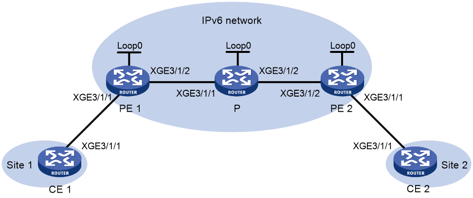
|
Device |
Interface |
IP address |
Device |
Interface |
IP address |
|
CE 1 |
XGE3/1/1 |
10::1/64 |
P |
Loop0 |
3::3/128 |
|
PE 1 |
Loop0 |
1::1/128 |
|
XGE3/1/1 |
20::2/64 |
|
|
XGE3/1/1 |
- |
|
XGE3/1/2 |
30::1/64 |
|
|
XGE3/1/2 |
20::1/64 |
PE 2 |
Loop0 |
2::2/128 |
|
CE 2 |
XGE3/1/1 |
10::2/64 |
|
XGE3/1/1 |
- |
|
|
|
|
|
XGE3/1/2 |
30::2/64 |
Procedure
1. Configure CE 1.
<CE1> system-view
[CE1] interface ten-gigabitethernet 3/1/1
[CE1-Ten-GigabitEthernet3/1/1] ipv6 address 10::1 64
[CE1-Ten-GigabitEthernet3/1/1] quit
2. Configure PE 1:
# Run OSPFv3 on PE 1 and use OSPFv3 to advertise SIDs.
<PE1> system-view
[PE1] ospfv3
[PE1-ospfv3-1] router-id 1.1.1.1
[PE1-ospfv3-1] segment-routing ipv6 locator aaa
[PE1-ospfv3-1] area 0.0.0.0
[PE1-ospfv3-1-area-0.0.0.0] quit
[PE1-ospfv3-1] quit
# Configure interface Loopback 0.
[PE1] interface loopback 0
[PE1-LoopBack0] ipv6 address 1::1 128
[PE1-LoopBack0] ospfv3 1 area 0
[PE1-LoopBack0] quit
# Enable L2VPN.
[PE1] l2vpn enable
# Configure Ten-GigabitEthernet 3/1/2, the interface connected to P.
[PE1] interface ten-gigabitethernet 3/1/2
[PE1-Ten-GigabitEthernet3/1/2] ipv6 address 20::1 64
[PE1-Ten-GigabitEthernet3/1/2] ospfv3 1 area 0
[PE1-Ten-GigabitEthernet3/1/2] undo shutdown
[PE1-Ten-GigabitEthernet3/1/2] quit
# Configure PE 1 to establish IBGP neighbor relationship with PE 2 and enable BGP EVPN to advertise routes in SRv6 encapsulation to PE 2.
[PE1] bgp 100
[PE1-bgp-default] router-id 1.1.1.1
[PE1-bgp-default] peer 2::2 as-number 100
[PE1-bgp-default] peer 2::2 connect-interface loopback 0
[PE1-bgp-default] address-family l2vpn evpn
[PE1-bgp-default-evpn] peer 2::2 enable
[PE1-bgp-default-evpn] peer 2::2 advertise encap-type srv6
[PE1-bgp-default-evpn] quit
[PE1-bgp-default] quit
# Create VSI vpna, create an EVPN instance for it, and enable SRv6 encapsulation. Configure an RD and route targets for the EVPN instance, enable the SID-route-recursion feature, and apply a locator to the EVPN instance.
[PE1] vsi vpna
[PE1-vsi-vpna] evpn encapsulation srv6
[PE1-vsi-vpna-evpn-srv6] route-distinguisher 1:1
[PE1-vsi-vpna-evpn-srv6] vpn-target 1:1 export-extcommunity
[PE1-vsi-vpna-evpn-srv6] vpn-target 1:1 import-extcommunity
[PE1-vsi-vpna-evpn-srv6] segment-routing ipv6 best-effort
[PE1-vsi-vpna-evpn-srv6] segment-routing ipv6 locator aaa
[PE1-vsi-vpna-evpn-srv6] quit
# Map Ten-GigabitEthernet 3/1/1 to the VSI.
[PE1] interface ten-gigabitethernet 3/1/1
[PE1-Ten-GigabitEthernet3/1/1] xconnect vsi vpna
[PE1-Ten-GigabitEthernet3/1/1] quit
# Specify a source IP address for the outer IPv6 header of SRv6-encapsulated packets, and configure a locator to apply for End.DT2U SIDs and End.DT2M SIDs.
[PE1] segment-routing ipv6
[PE1-segment-routing-ipv6] encapsulation source-address 1::1
[PE1-segment-routing-ipv6] locator aaa ipv6-prefix 100:: 64 static 32
[PE1-segment-routing-ipv6-locator-aaa] quit
[PE1-segment-routing-ipv6] quit
3. Configure PE 2:
# Run OSPFv3 on PE 2 and use OSPFv3 to advertise SIDs.
<PE2> system-view
[PE2] ospfv3
[PE2-ospfv3-1] router-id 2.2.2.2
[PE2-ospfv3-1] segment-routing ipv6 locator aaa
[PE2-ospfv3-1] area 0.0.0.0
[PE2-ospfv3-1-area-0.0.0.0] quit
[PE2-ospfv3-1] quit
# Configure interface Loopback 0.
[PE2] interface loopback 0
[PE2-LoopBack0] ipv6 address 2::2 128
[PE2-LoopBack0] ospfv3 1 area 0
[PE2-LoopBack0] quit
# Enable L2VPN.
[PE2] l2vpn enable
# Configure Ten-GigabitEthernet 3/1/2, the interface connected to P.
[PE2] interface ten-gigabitethernet 3/1/2
[PE2-Ten-GigabitEthernet3/1/2] ipv6 address 30::2 64
[PE2-Ten-GigabitEthernet3/1/2] ospfv3 1 area 0.0.0.0
[PE2-Ten-GigabitEthernet3/1/2] undo shutdown
[PE2-Ten-GigabitEthernet3/1/2] quit
# Configure PE 2 to establish IBGP neighbor relationship with PE 1, and enable BGP EVPN to advertise routes in SRv6 encapsulation to PE 1.
[PE2] bgp 100
[PE2-bgp-default] router-id 2.2.2.2
[PE2-bgp-default] peer 1::1 as-number 100
[PE2-bgp-default] peer 1::1 connect-interface loopback 0
[PE2-bgp-default] address-family l2vpn evpn
[PE2-bgp-default-evpn] peer 1::1 enable
[PE2-bgp-default-evpn] peer 1::1 advertise encap-type srv6
[PE2-bgp-default-evpn] quit
[PE2-bgp-default] quit
# Create VSI vpna, create an EVPN instance for it, and enable SRv6 encapsulation. Configure an RD and route targets for the EVPN instance, enable the SID-route-recursion feature, and apply a locator to the EVPN instance.
[PE2] vsi vpna
[PE2-vsi-vpna] evpn encapsulation srv6
[PE2-vsi-vpna-evpn-srv6] route-distinguisher 1:1
[PE2-vsi-vpna-evpn-srv6] vpn-target 1:1 export-extcommunity
[PE2-vsi-vpna-evpn-srv6] vpn-target 1:1 import-extcommunity
[PE2-vsi-vpna-evpn-srv6] segment-routing ipv6 best-effort
[PE2-vsi-vpna-evpn-srv6] segment-routing ipv6 locator aaa
[PE2-vsi-vpna-evpn-srv6] quit
# Map Ten-GigabitEthernet 3/1/1 to the VSI.
[PE2] interface ten-gigabitethernet 3/1/1
[PE2-Ten-GigabitEthernet3/1/1] xconnect vsi vpna
[PE2-Ten-GigabitEthernet3/1/1] quit
# Specify a source IP address for the outer IPv6 header of SRv6-encapsulated packets, and configure a locator to apply for End.DT2U SIDs and End.DT2M SIDs.
[PE2] segment-routing ipv6
[PE2-segment-routing-ipv6] encapsulation source-address 2::2
[PE2-segment-routing-ipv6] locator aaa ipv6-prefix 200:: 64 static 32
[PE2-segment-routing-ipv6-locator-aaa] quit
[PE2-segment-routing-ipv6] quit
4. Configure P:
# Run OSPFv3 on P.
<P> system-view
[P] ospfv3
[P-ospfv3-1] router-id 3.3.3.3
[P-ospfv3-1] area 0.0.0.0
[P-ospfv3-1-area-0.0.0.0] quit
[P-ospfv3-1] quit
# Configure IPv6 addresses for interfaces and run OSPFv3 on the interfaces.
[P] interface loopback 0
[P-LoopBack0] ipv6 address 3::3 128
[P-LoopBack0] ospfv3 1 area 0
[P-LoopBack0] quit
[P] interface ten-gigabitethernet 3/1/1
[P-Ten-GigabitEthernet3/1/1] ipv6 address 20::2 64
[P-Ten-GigabitEthernet3/1/1] ospfv3 1 area 0
[P-Ten-GigabitEthernet3/1/1] quit
[P] interface ten-gigabitethernet 3/1/2
[P-Ten-GigabitEthernet3/1/2] ipv6 address 30::1 64
[P-Ten-GigabitEthernet3/1/2] ospfv3 1 area 0
[P-Ten-GigabitEthernet3/1/2] quit
5. Configure CE 2.
<CE2> system-view
[CE2] interface ten-gigabitethernet 3/1/1
[CE2-Ten-GigabitEthernet3/1/1] ipv6 address 10::2 64
[CE2-Ten-GigabitEthernet3/1/1] quit
Verifying the configuration
# Verify that an SRv6 tunnel has been established between PE 1 and PE 2.
[PE1] display l2vpn peer srv6
Total number of SRv6 Tunnels: 1
1 up, 0 blocked, 0 down
VSI Name: vpna
Peer : 2::2
Flag : Main
State : Up
# Verify that the SRv6 forwarding information on PE 1 is correct.
[PE1] display l2vpn forwarding srv6
Total number of VSIs: 1
Total number of SRv6 tunnels: 1, 1 up, 0 blocked, 0 down
VSI Name : vpna
Link ID : 0x9000000 Type: BE State: Up
In SID : 100::1:0:1
Out SID : 200::1:0:0
# Verify that CE 1 and CE 2 can ping each other. (Details not shown.)
Example: Configuring EVPN VPLS over SRv6 multihoming (S-Trunk dual-homed)
Network configuration
As shown in Figure 8, CE 1 is dual-homed to PE 1 and PE 2 through S-Trunk. Configure EVPN VPLS over SRv6 for dual-homed site 1 and single-homed site 2 to communicate over the IPv6 backbone network through an SRv6 tunnel.
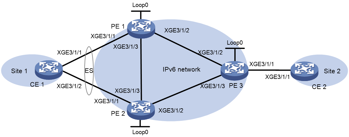
|
Device |
Interface |
IP address |
Device |
Interface |
IP address |
|
PE 1 |
Loop0 |
1::1/128 |
PE 2 |
Loop0 |
2::2/128 |
|
|
XGE3/1/1 |
N/A |
|
XGE3/1/1 |
N/A |
|
|
XGE3/1/2 |
10::1/64 |
|
XGE3/1/2 |
30::2/64 |
|
|
XGE3/1/3 |
20::1/64 |
|
XGE3/1/3 |
20::2/64 |
|
|
XGE3/1/3 |
10.1.2.1/24 |
|
XGE3/1/3 |
10.1.2.2/24 |
|
PE 3 |
Loop0 |
3::3/128 |
CE 1 |
RAGG1 |
100::1/64 |
|
|
XGE3/1/1 |
N/A |
CE 2 |
XGE3/1/1 |
100::2/64 |
|
|
XGE3/1/2 |
10::3/64 |
|
|
|
|
|
XGE3/1/3 |
30::3/64 |
|
|
|
Procedure
1. Configure CE 1:
# Create dynamic Layer 3 aggregate interface 1 and assign it an IPv6 address and prefix.
<CE1> system-view
[CE1] interface route-aggregation 1
[CE1-Route-Aggregation1] link-aggregation mode dynamic
[CE1-Route-Aggregation1] ipv6 address 100::1 64
[CE1-Route-Aggregation1] quit
# Assign Ten-GigabitEthernet 3/1/1 and Ten-GigabitEthernet 3/1/2 to aggregation group 1.
[CE1] interface ten-gigabitethernet 3/1/1
[CE1-Ten-GigabitEthernet3/1/1] port link-aggregation group 1
[CE1-Ten-GigabitEthernet3/1/1] quit
[CE1] interface ten-gigabitethernet 3/1/2
[CE1-Ten-GigabitEthernet3/1/2] port link-aggregation group 1
[CE1-Ten-GigabitEthernet3/1/2] quit
2. Configure PE 1:
# Run OSPFv3 on PE 1.
<PE1> system-view
[PE1] ospfv3
[PE1-ospfv3-1] router-id 1.1.1.1
[PE1-ospfv3-1] segment-routing ipv6 locator aaa
[PE1-ospfv3-1] area 0
[PE1-ospfv3-1-area-0.0.0.0] quit
[PE1-ospfv3-1] quit
# Configure interface Loopback 0.
[PE1] interface loopback 0
[PE1-LoopBack0] ipv6 address 1::1 128
[PE1-LoopBack0] ospfv3 1 area 0
[PE1-LoopBack0] quit
# Enable L2VPN.
[PE1] l2vpn enable
# Configure Ten-GigabitEthernet 3/1/2, the interface connected to PE 3.
[PE1] interface ten-gigabitethernet 3/1/2
[PE1-Ten-GigabitEthernet3/1/2] ipv6 address 10::1/64
[PE1-Ten-GigabitEthernet3/1/2] ospfv3 1 area 0
[PE1-Ten-GigabitEthernet3/1/2] undo shutdown
[PE1-Ten-GigabitEthernet3/1/2] quit
# Configure Ten-GigabitEthernet 3/1/3, the interface connected to PE 2.
[PE1] interface ten-gigabitethernet 3/1/3
[PE1-Ten-GigabitEthernet3/1/3] ipv6 address 20::1/64
[PE1-Ten-GigabitEthernet3/1/3] ospfv3 1 area 0
[PE1-Ten-GigabitEthernet3/1/3] undo shutdown
[PE1-Ten-GigabitEthernet3/1/3] quit
# Configure PE 1 to establish IBGP neighbor relationships with PE 2 and PE 3, and enable BGP EVPN to advertise routes in SRv6 encapsulation to PE 2 and PE 3.
[PE1] bgp 100
[PE1-bgp-default] router-id 1.1.1.1
[PE1-bgp-default] peer 2::2 as-number 100
[PE1-bgp-default] peer 2::2 connect-interface loopback 0
[PE1-bgp-default] peer 3::3 as-number 100
[PE1-bgp-default] peer 3::3 connect-interface loopback 0
[PE1-bgp-default] address-family l2vpn evpn
[PE1-bgp-default-evpn] peer 2::2 enable
[PE1-bgp-default-evpn] peer 3::3 enable
[PE1-bgp-default-evpn] peer 2::2 advertise encap-type srv6
[PE1-bgp-default-evpn] peer 3::3 advertise encap-type srv6
[PE1-bgp-default-evpn] quit
[PE1-bgp-default] quit
# Create VSI vpna, create an EVPN instance for it, and enable SRv6 encapsulation. Configure an RD and route targets for the EVPN instance, enable the SID-route-recursion feature, and apply a locator to the EVPN instance.
[PE1] vsi vpna
[PE1-vsi-vpna] ignore-ac-state enable
[PE1-vsi-vpna] evpn encapsulation srv6
[PE1-vsi-vpna-evpn-srv6] route-distinguisher 1:1
[PE1-vsi-vpna-evpn-srv6] vpn-target 1:1 export-extcommunity
[PE1-vsi-vpna-evpn-srv6] vpn-target 1:1 import-extcommunity
[PE1-vsi-vpna-evpn-srv6] segment-routing ipv6 best-effort
[PE1-vsi-vpna-evpn-srv6] segment-routing ipv6 locator aaa
[PE1-vsi-vpna-evpn-srv6] quit
# Configure S-Trunk for CE 1 to be dual-homed to PE 1 and PE 2.
[PE1] lacp system-priority 10
[PE1] lacp system-mac 1-1-1
[PE1] lacp system-number 1
[PE1] s-trunk id 1
[PE1-s-trunk1] s-trunk ip destination 10.1.2.2 source 10.1.2.1
[PE1-s-trunk1] quit
[PE1] interface route-aggregation 1
[PE1-Route-Aggregation1] link-aggregation mode dynamic
[PE1-Route-Aggregation1] s-trunk 1
[PE1-Route-Aggregation1] s-trunk port-role primary
[PE1-Route-Aggregation1] quit
[PE1] interface ten-gigabitethernet 3/1/1
[PE1-Ten-GigabitEthernet3/1/1] port link-aggregation group 1
[PE1-Ten-GigabitEthernet3/1/1] quit
# Assign an ESI to site-facing interface Route-Aggregation 1, set the redundancy mode of the interface to all-active, and map the interface to VSI vpna.
[PE1] interface route-aggregation 1
[PE1-Route-Aggregation1] esi 1.1.1.1.1
[PE1-Route-Aggregation1] evpn redundancy-mode all-active
[PE1-Route-Aggregation1] xconnect vsi vpna
[PE1-Route-Aggregation1] quit
# Specify a source IP address for the outer IPv6 header of SRv6-encapsulated packets, and configure a locator to apply for End.DT2U SIDs and End.DT2M SIDs.
[PE1] segment-routing ipv6
[PE1-segment-routing-ipv6] encapsulation source-address 1::1
[PE1-segment-routing-ipv6] locator aaa ipv6-prefix 111:: 64 static 32
[PE1-segment-routing-ipv6-locator-aaa] quit
[PE1-segment-routing-ipv6] quit
3. Configure PE 2:
# Run OSPFv3 on PE 2.
<PE2> system-view
[PE2] ospfv3
[PE2-ospfv3-1] router-id 2.2.2.2
[PE2-ospfv3-1] segment-routing ipv6 locator aaa
[PE2-ospfv3-1] area 0.0.0.0
[PE2-ospfv3-1-area-0.0.0.0] quit
[PE2-ospfv3-1] quit
# Configure interface Loopback 0.
[PE2] interface loopback 0
[PE2-LoopBack0] ipv6 address 2::2 128
[PE2-LoopBack0] ospfv3 1 area 0
[PE2-LoopBack0] quit
# Enable L2VPN.
[PE2] l2vpn enable
# Configure Ten-GigabitEthernet 3/1/3, the interface connected to PE 1.
[PE2] interface ten-gigabitethernet 3/1/3
[PE2-Ten-GigabitEthernet3/1/3] ipv6 address 20::2 64
[PE2-Ten-GigabitEthernet3/1/3] ospfv3 1 area 0
[PE2-Ten-GigabitEthernet3/1/3] undo shutdown
[PE2-Ten-GigabitEthernet3/1/3] quit
# ConfigureTen-GigabitEthernet 3/1/2, the interface connected to PE 3.
[PE2] interface ten-gigabitethernet 3/1/2
[PE2-Ten-GigabitEthernet3/1/2] ipv6 address 30::2 64
[PE2-Ten-GigabitEthernet3/1/2] ospfv3 1 area 0
[PE2-Ten-GigabitEthernet3/1/2] undo shutdown
[PE2-Ten-GigabitEthernet3/1/2] quit
# Configure PE 2 to establish IBGP neighbor relationships with PE 1 and PE 3, and enable BGP EVPN to advertise routes in SRv6 encapsulation to PE 1 and PE 3.
[PE2] bgp 100
[PE2-bgp-default] router-id 2.2.2.2
[PE2-bgp-default] peer 1::1 as-number 100
[PE2-bgp-default] peer 1::1 connect-interface loopback 0
[PE2-bgp-default] peer 3::3 as-number 100
[PE2-bgp-default] peer 3::3 connect-interface loopback 0
[PE2-bgp-default] address-family l2vpn evpn
[PE2-bgp-default-evpn] peer 1::1 enable
[PE2-bgp-default-evpn] peer 3::3 enable
[PE2-bgp-default-evpn] peer 1::1 advertise encap-type srv6
[PE2-bgp-default-evpn] peer 3::3 advertise encap-type srv6
[PE2-bgp-default-evpn] quit
[PE2-bgp-default] quit
# Create VSI vpna, create an EVPN instance for it, and enable SRv6 encapsulation. Configure an RD and route targets for the EVPN instance, enable the SID-route-recursion feature, and apply a locator to the EVPN instance.
[PE2] vsi vpna
[PE2-vsi-vpna] ignore-ac-state enable
[PE2-vsi-vpna] evpn encapsulation srv6
[PE2-vsi-vpna-evpn-srv6] route-distinguisher 1:1
[PE2-vsi-vpna-evpn-srv6] vpn-target 1:1 export-extcommunity
[PE2-vsi-vpna-evpn-srv6] vpn-target 1:1 import-extcommunity
[PE2-vsi-vpna-evpn-srv6] segment-routing ipv6 best-effort
[PE2-vsi-vpna-evpn-srv6] segment-routing ipv6 locator aaa
[PE2-vsi-vpna-evpn-srv6] quit
# Configure S-Trunk for CE 1 to be dual-homed to PE 1 and PE 2.
[PE2] lacp system-priority 10
[PE2] lacp system-mac 1-1-1
[PE2] lacp system-number 2
[PE2] s-trunk id 1
[PE2-s-trunk1] s-trunk ip destination 10.1.2.1 source 10.1.2.2
[PE2-s-trunk1] quit
[PE2] interface route-aggregation 1
[PE2-Route-Aggregation1] link-aggregation mode dynamic
[PE2-Route-Aggregation1] s-trunk 1
[PE2-Route-Aggregation1] s-trunk port-role primary
[PE2-Route-Aggregation1] quit
[PE2] interface ten-gigabitethernet 3/1/1
[PE2-Ten-GigabitEthernet3/1/1] port link-aggregation group 1
[PE2-Ten-GigabitEthernet3/1/1] quit
# Assign an ESI to site-facing interface Route-Aggregation 1, set the redundancy mode of the interface to all-active, and map the interface to VSI vpna.
[PE2] interface route-aggregation 1
[PE2-Route-Aggregation1] esi 1.1.1.1.1
[PE2-Route-Aggregation1] evpn redundancy-mode all-active
[PE2-Route-Aggregation1] xconnect vsi vpna
[PE2-Route-Aggregation1] quit
# Specify a source IP address for the outer IPv6 header of SRv6-encapsulated packets, and configure a locator to apply for End.DT2U SIDs and End.DT2M SIDs.
[PE2] segment-routing ipv6
[PE2-segment-routing-ipv6] encapsulation source-address 2::2
[PE2-segment-routing-ipv6] locator aaa ipv6-prefix 222:: 64 static 32
[PE2-segment-routing-ipv6-locator-aaa] quit
[PE2-segment-routing-ipv6] quit
4. Configure PE 3:
# Run OSPFv3 on PE 3.
<PE3> system-view
[PE3] ospfv3
[PE3-ospfv3-1] router-id 3.3.3.3
[PE3-ospfv3-1] segment-routing ipv6 locator aaa
[PE3-ospfv3-1] area 0
[PE3-ospfv3-1-area-0.0.0.0] quit
[PE3-ospfv3-1] quit
# Configure interface Loopback 0.
[PE3] interface loopback 0
[PE3-LoopBack0] ipv6 address 3::3 128
[PE3-LoopBack0] ospfv3 1 area 0
[PE3-LoopBack0] quit
# Enable L2VPN.
[PE3] l2vpn enable
# Configure Ten-GigabitEthernet 3/1/2, the interface connected to PE 1.
[PE3] interface ten-gigabitethernet 3/1/2
[PE3-Ten-GigabitEthernet3/1/2] ipv6 address 10::3 64
[PE3-Ten-GigabitEthernet3/1/2] ospfv3 1 area 0
[PE3-Ten-GigabitEthernet3/1/2] undo shutdown
[PE3-Ten-GigabitEthernet3/1/2] quit
# Configure Ten-GigabitEthernet 3/1/3, the interface connected to PE 2.
[PE3] interface ten-gigabitethernet 3/1/3
[PE3-Ten-GigabitEthernet3/1/3] ipv6 address 30::3 64
[PE3-Ten-GigabitEthernet3/1/3] ospfv3 1 area 0
[PE3-Ten-GigabitEthernet3/1/3] undo shutdown
[PE3-Ten-GigabitEthernet3/1/3] quit
# Configure PE 3 to establish IBGP neighbor relationships with PE 1 and PE 2, and enable BGP EVPN to advertise routes in SRv6 encapsulation to PE 1 and PE 2.
[PE3] bgp 100
[PE3-bgp-default] router-id 3.3.3.3
[PE3-bgp-default] peer 1::1 as-number 100
[PE3-bgp-default] peer 1::1 connect-interface loopback 0
[PE3-bgp-default] peer 2::2 as-number 100
[PE3-bgp-default] peer 2::2 connect-interface loopback 0
[PE3-bgp-default] address-family l2vpn evpn
[PE3-bgp-default-evpn] peer 1::1 enable
[PE3-bgp-default-evpn] peer 2::2 enable
[PE3-bgp-default-evpn] peer 1::1 advertise encap-type srv6
[PE3-bgp-default-evpn] peer 2::2 advertise encap-type srv6
[PE3-bgp-default-evpn] quit
[PE3-bgp-default] quit
# Create VSI vpna, create an EVPN instance for it, and enable SRv6 encapsulation. Configure an RD and route targets for the EVPN instance, enable the SID-route-recursion feature, and apply a locator to the EVPN instance.
[PE3] vsi vpna
[PE3-vsi-vpna] evpn encapsulation srv6
[PE3-vsi-vpna-evpn-srv6] route-distinguisher 1:1
[PE3-vsi-vpna-evpn-srv6] vpn-target 1:1 export-extcommunity
[PE3-vsi-vpna-evpn-srv6] vpn-target 1:1 import-extcommunity
[PE3-vsi-vpna-evpn-srv6] segment-routing ipv6 best-effort
[PE3-vsi-vpna-evpn-srv6] segment-routing ipv6 locator aaa
[PE3-vsi-vpna-evpn-srv6] quit
# Map Ten-GigabitEthernet 3/1/1 to the VSI.
[PE3] interface ten-gigabitethernet 3/1/1
[PE3-Ten-GigabitEthernet3/1/1] xconnect vsi vpna
[PE3-Ten-GigabitEthernet3/1/1] quit
# Specify a source IP address for the outer IPv6 header of SRv6-encapsulated packets, and configure a locator to apply for End.DT2U SIDs and End.DT2M SIDs.
[PE3] segment-routing ipv6
[PE3-segment-routing-ipv6] encapsulation source-address 3::3
[PE3-segment-routing-ipv6] locator aaa ipv6-prefix 333:: 64 static 32
[PE3-segment-routing-ipv6-locator-aaa] quit
[PE3-segment-routing-ipv6] quit
5. Configure CE 2.
<CE2> system-view
[CE2] interface ten-gigabitethernet 3/1/1
[CE2-Ten-GigabitEthernet3/1/1] ipv6 address 100::2 64
[CE2-Ten-GigabitEthernet3/1/1] quit
Verifying the configuration
# Verify that PE 3 has established SRv6 tunnels to PE 1 and PE 2. The SRv6 tunnels are ECMP tunnels that can load share traffi.
[PE3] display l2vpn peer srv6
Total number of SRv6 Tunnels: 2
2 up, 0 blocked, 0 down
VSI Name: vpna
Peer : 1::1
Flag : Main
State : Up
Peer : 2::2
Flag : Main
State : Up
# Verify that the SRv6 forwarding information on PE 3 is correct.
[PE3] display l2vpn forwarding srv6
Total number of VSIs: 1
Total number of SRv6 tunnels: 2, 2 up, 0 blocked, 0 down
VSI Name : vpna
Link ID : 0x9000000 Type: BE State: Up
In SID : 333::1:0:4
Out SID : 111::1:0:4
Link ID : 0x9000001 Type: BE State: Up
In SID : 333::1:0:4
Out SID : 222::1:0:3
# Verify that CE 1 and CE 2 can ping each other. (Details not shown.)
# Verify that CE 1 and CE 2 can ping each other when the PW on PE 1 or PE 2 fails. (Details not shown.)
Example: Configuring LDP PWs as ACs for SRv6 PWs
Network configuration
As shown in Figure 9:
· PE 1 and PE 2 are edge devices on both the MPLS network and SRv6 network.
· Configure VPLS on PE 1, PE 2, and PE 4, and configure the PEs to use LDP to establish LDP PWs.
· Configure EVPN VPLS over SRv6 on PE 1, PE 2, and PE 3.
· On PE 1 and PE 2, configure LDP PWs as UPWs (ACs) for SRv6 PWs to ensure that the VPLS and EVPN VPLS over SRv6 networks can communicate with each other.
· PE 4 is dual-homed to PE 1 and PE 2 through two LDP PWs (UPWs).
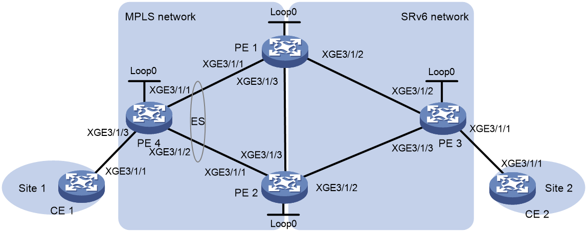
|
Device |
Interface |
IP address |
Device |
Interface |
IP address |
|
PE 1 |
Loop0 |
1::1/128 |
PE 3 |
Loop0 |
3::3/128 |
|
|
Loop0 |
1.1.1.9/32 |
|
XGE3/1/1 |
- |
|
|
XGE3/1/1 |
10.1.1.1/24 |
|
XGE3/1/2 |
10::3/64 |
|
|
XGE3/1/2 |
10::1/64 |
|
XGE3/1/3 |
30::3/64 |
|
|
XGE3/1/3 |
20::1/64 |
PE 4 |
Loop0 |
4.4.4.9 |
|
PE 2 |
Loop0 |
2::2/128 |
|
XGE3/1/1 |
10.1.1.4/24 |
|
|
Loop0 |
2.2.2.9/32 |
|
XGE3/1/2 |
20.1.1.4/24 |
|
|
XGE3/1/1 |
20.1.1.2/24 |
|
XGE3/1/3 |
- |
|
|
XGE3/1/2 |
30::2/64 |
CE 1 |
XGE3/1/1 |
100::1/64 |
|
|
XGE3/1/3 |
20::2/64 |
CE2 |
XGE3/1/1 |
100::2/64 |
Procedure
1. Configure CE 1:
# Configure an IP address and mask for Ten-GigabitEthernet 3/1/1.
<CE1> system-view
[CE1] interface ten-gigabitethernet 3/1/1
[CE1-Ten-GigabitEthernet3/1/1] ipv6 address 100::1 64
[CE1-Ten-GigabitEthernet3/1/1] quit
2. Configure PE 4:
# Configure MPLS basic capabilities.
<PE4> system-view
[PE4] interface loopback 0
[PE4-LoopBack0] ip address 4.4.4.9 32
[PE4-LoopBack0] ospf 1 area 0
[PE4-LoopBack0] quit
[PE4] mpls lsr-id 4.4.4.9
[PE4] mpls ldp
[PE4-ldp] quit
# Enable L2VPN.
[PE4] l2vpn enable
# Configure Ten-GigabitEthernet 3/1/1, the interface connected to PE 1.
[PE4] interface ten-gigabitethernet 3/1/1
[PE4-Ten-GigabitEthernet3/1/1] ip address 10.1.1.4 24
[PE4-Ten-GigabitEthernet3/1/1] ospf 1 area 0
[PE4-Ten-GigabitEthernet3/1/1] mpls enable
[PE4-Ten-GigabitEthernet3/1/1] mpls ldp enable
[PE4-Ten-GigabitEthernet3/1/1] undo shutdown
[PE4-Ten-GigabitEthernet3/1/1] quit
# Configure Ten-GigabitEthernet 3/1/2, the interface connected to PE 2.
[PE4] interface ten-gigabitethernet 3/1/2
[PE4-Ten-GigabitEthernet3/1/2] ip address 20.1.1.4 24
[PE4-Ten-GigabitEthernet3/1/2] ospf 1 area 0
[PE4-Ten-GigabitEthernet3/1/2] mpls enable
[PE4-Ten-GigabitEthernet3/1/2] mpls ldp enable
[PE4-Ten-GigabitEthernet3/1/2] undo shutdown
[PE4-Ten-GigabitEthernet3/1/2] quit
# Configure VSI vpna to use LDP to establish LDP PWs. The LDP PW between PE 1 and PE 4 is the primary PW and the LDP PW between PE 2 and PE 4 is the backup PW. Enable the dual receive feature for PW redundancy.
[PE4] vsi vpna
[PE4-vsi-vpna] protection dual-receive
[PE4-vsi-vpna] pwsignaling ldp
[PE4-vsi-vpna-ldp] peer 1.1.1.9 pw-id 500
[PE4-vsi-vpna-ldp-1.1.1.9-500] backup-peer 2.2.2.9 pw-id 500
[PE4-vsi-vpna-ldp-1.1.1.9-500-backup] quit
[PE4-vsi-vpna-ldp-1.1.1.9-500] quit
[PE4-vsi-vpna-ldp] quit
[PE4-vsi-vpna] quit
# Map Ten-GigabitEthernet 3/1/3 to VSI vpna.
[PE4] interface ten-gigabitethernet 3/1/3
[PE4-Ten-GigabitEthernet3/1/3] xconnect vsi vpna
[PE4-Ten-GigabitEthernet3/1/3] quit
3. Configure PE 1:
# Run OSPF on PE 1.
<PE1> system-view
[PE1] ospf
[PE1-ospf-1] area 0
[PE1-ospf-1-area-0.0.0.0] network 1.1.1.9 0.0.0.0
[PE1-ospf-1-area-0.0.0.0] network 10.1.1.0 0.0.0.255
[PE1-ospf-1-area-0.0.0.0] quit
[PE1-ospf-1] quit
# Run OSPFv3 on PE 1.
<PE1> system-view
[PE1] ospfv3
[PE1-ospfv3-1] router-id 1.1.1.9
[PE1-ospfv3-1] segment-routing ipv6 locator aaa
[PE1-ospfv3-1] area 0
[PE1-ospfv3-1-area-0.0.0.0] quit
[PE1-ospfv3-1] quit
# Configure interface Loopback 0.
[PE1] interface loopback 0
[PE1-LoopBack0] ip address 1.1.1.9 32
[PE1-LoopBack0] ipv6 address 1::1 128
[PE1-LoopBack0] ospfv3 1 area 0
[PE1-LoopBack0] quit
# Configure MPLS basic capabilities.
[PE1] mpls lsr-id 1.1.1.9
[PE1] mpls ldp
[PE1-ldp] quit
# Enable L2VPN.
[PE1] l2vpn enable
# Configure Ten-GigabitEthernet 3/1/1, the interface connected to PE 4.
[PE1] interface ten-gigabitethernet 3/1/1
[PE1-Ten-GigabitEthernet3/1/1] ip address 10.1.1.1 24
[PE1-Ten-GigabitEthernet3/1/1] mpls enable
[PE1-Ten-GigabitEthernet3/1/1] mpls ldp enable
[PE1-Ten-GigabitEthernet3/1/1] undo shutdown
[PE1-Ten-GigabitEthernet3/1/1] quit
# Configure Ten-GigabitEthernet 3/1/2, the interface connected to PE 3.
[PE1] interface ten-gigabitethernet 3/1/2
[PE1-Ten-GigabitEthernet3/1/2] ipv6 address 10::1 64
[PE1-Ten-GigabitEthernet3/1/2] ospfv3 1 area 0
[PE1-Ten-GigabitEthernet3/1/2] quit
# ConfigureTen-GigabitEthernet 3/1/3, the interface connected to PE 2.
[PE1] interface ten-gigabitethernet 3/1/3
[PE1-Ten-GigabitEthernet3/1/3] ipv6 address 20::1 64
[PE1-Ten-GigabitEthernet3/1/3] ospfv3 1 area 0
[PE1-Ten-GigabitEthernet3/1/3] quit
# Establish IBGP connections to PE 2 and PE 3, and enable BGP EVPN to advertise route information to PE 2 and PE 3.
[PE1] bgp 100
[PE1-bgp-default] router-id 1.1.1.9
[PE1-bgp-default] peer 2::2 as-number 100
[PE1-bgp-default] peer 2::2 connect-interface loopback 0
[PE1-bgp-default] peer 3::3 as-number 100
[PE1-bgp-default] peer 3::3 connect-interface loopback 0
[PE1-bgp-default] address-family l2vpn evpn
[PE1-bgp-default-evpn] peer 2::2 enable
[PE1-bgp-default-evpn] peer 3::3 enable
[PE1-bgp-default-evpn] peer 2::2 advertise encap-type srv6
[PE1-bgp-default-evpn] peer 3::3 advertise encap-type srv6
[PE1-bgp-default-evpn] quit
[PE1-bgp-default] quit
# Create VSI vpna, create an EVPN instance for it, enable SRv6 encapsulation, and configure an RD and route targets for the EVPN instance. Enable SRv6 BE route recursion mode and apply a locator to the EVPN instance.
[PE1] vsi vpna
[PE1-vsi-vpna] evpn encapsulation srv6
[PE1-vsi-vpna-evpn-srv6] route-distinguisher 1:1
[PE1-vsi-vpna-evpn-srv6] vpn-target 1:1 export-extcommunity
[PE1-vsi-vpna-evpn-srv6] vpn-target 1:1 import-extcommunity
[PE1-vsi-vpna-evpn-srv6] segment-routing ipv6 best-effort
[PE1-vsi-vpna-evpn-srv6] segment-routing ipv6 locator aaa
[PE1-vsi-vpna-evpn-srv6] quit
# Configure VSI vpna to use LDP to establish LDP PWs. Configure PE 1 to establish an UPW with PE 4, assign an ESI to the UPW, and set the redundancy mode of the UPW to all-active.
[PE1-vsi-vpna] pwsignaling ldp
[PE1-vsi-vpna-ldp] peer 4.4.4.9 pw-id 500 no-split-horizon
[PE1-vsi-vpna-ldp-4.4.4.9-500] esi 1.1.1.1.1
[PE1-vsi-vpna-ldp-4.4.4.9-500] evpn redundancy-mode all-active
[PE1-vsi-vpna-ldp-4.4.4.9-500] quit
[PE1-vsi-vpna-ldp] quit
# Configure a locator to apply for End.DT2U SIDs and End.DT2M SIDs.
[PE1] segment-routing ipv6
[PE1-segment-routing-ipv6] encapsulation source-address 1::1
[PE1-segment-routing-ipv6] locator aaa ipv6-prefix 111:: 64 static 32
[PE1-segment-routing-ipv6-locator-aaa] quit
[PE1-segment-routing-ipv6] quit
4. Configure PE 2:
# Run OSPF on PE 2.
<PE2> system-view
[PE2] ospf
[PE2-ospf-1] area 0.0.0.0
[PE2-ospf-1-area-0.0.0.0] network 2.2.2.9 0.0.0.0
[PE2-ospf-1-area-0.0.0.0] network 20.1.1.0 0.0.0.255
[PE2-ospf-1-area-0.0.0.0] quit
[PE2-ospf-1] quit
# Run OSPFv3 on PE 2.
<PE2> system-view
[PE2] ospfv3
[PE2-ospfv3-1] router-id 2.2.2.9
[PE2-ospfv3-1] segment-routing ipv6 locator aaa
[PE2-ospfv3-1] area 0.0.0.0
[PE2-ospfv3-1-area-0.0.0.0] quit
[PE2-ospfv3-1] quit
# Configure interface Loopback 0.
[PE2] interface loopback 0
[PE2-LoopBack1] ip address 2.2.2.9 32
[PE2-LoopBack0] ipv6 address 2::2 128
[PE2-LoopBack0] ospfv3 1 area 0
[PE2-LoopBack0] quit
# Configure MPLS basic capabilities.
[PE2] mpls lsr-id 2.2.2.9
[PE2] mpls ldp
[PE2-ldp] quit
# Enable L2VPN.
[PE2] l2vpn enable
# Configure Ten-GigabitEthernet 3/1/3, the interface connected to PE 1.
[PE2] interface ten-gigabitethernet 3/1/3
[PE2-Ten-GigabitEthernet3/1/3] ipv6 address 20::2 64
[PE2-Ten-GigabitEthernet3/1/3] ospfv3 1 area 0
[PE2-Ten-GigabitEthernet3/1/3] undo shutdown
[PE2-Ten-GigabitEthernet3/1/3] quit
# Configure Ten-GigabitEthernet 3/1/2, the interface connected to PE 3.
[PE2] interface ten-gigabitethernet 3/1/2
[PE2-Ten-GigabitEthernet3/1/2] ipv6 address 30::2 64
[PE2-Ten-GigabitEthernet3/1/2] ospfv3 1 area 0
[PE2-Ten-GigabitEthernet3/1/2] undo shutdown
[PE2-Ten-GigabitEthernet3/1/2] quit
# Configure Ten-GigabitEthernet 3/1/1, the interface connected to PE 4.
[PE2] interface ten-gigabitethernet 3/1/1
[PE2-Ten-GigabitEthernet3/1/1] ip address 20.1.1.2 24
[PE2-Ten-GigabitEthernet3/1/1] mpls enable
[PE2-Ten-GigabitEthernet3/1/1] mpls ldp enable
[PE2-Ten-GigabitEthernet3/1/1] undo shutdown
[PE2-Ten-GigabitEthernet3/1/1] quit
# Establish IBGP connections to PE 1 and PE 3 and enable BGP EVPN to advertise route information to PE 1 and PE 3.
[PE2] bgp 100
[PE2-bgp-default] router-id 2.2.2.9
[PE2-bgp-default] peer 1::1 as-number 100
[PE2-bgp-default] peer 1::1 connect-interface loopback 0
[PE2-bgp-default] peer 3::3 as-number 100
[PE2-bgp-default] peer 3::3 connect-interface loopback 0
[PE2-bgp-default] address-family l2vpn evpn
[PE2-bgp-default-evpn] peer 1::1 enable
[PE2-bgp-default-evpn] peer 3::3 enable
[PE2-bgp-default-evpn] peer 1::1 advertise encap-type srv6
[PE2-bgp-default-evpn] peer 3::3 advertise encap-type srv6
[PE2-bgp-default-evpn] quit
[PE2-bgp-default] quit
# Create VSI vpna, create an EVPN instance for it, enable SRv6 encapsulation, and configure an RD and route targets for the EVPN instance. Enable SRv6 BE route recursion mode and apply a locator to the EVPN instance.
[PE2] vsi vpna
[PE2-vsi-vpna] evpn encapsulation srv6
[PE2-vsi-vpna-evpn-srv6] route-distinguisher 1:1
[PE2-vsi-vpna-evpn-srv6] vpn-target 1:1 export-extcommunity
[PE2-vsi-vpna-evpn-srv6] vpn-target 1:1 import-extcommunity
[PE2-vsi-vpna-evpn-srv6] segment-routing ipv6 best-effort
[PE2-vsi-vpna-evpn-srv6] segment-routing ipv6 locator aaa
[PE2-vsi-vpna-evpn-srv6] quit
# Configure VSI vpna to use LDP to establish LDP PWs. Configure PE 2 to establish an UPW with PE 4, assign an ESI to the UPW, and set the redundancy mode of the UPW to all-active.
[PE2-vsi-vpna] pwsignaling ldp
[PE2-vsi-vpna-ldp] peer 4.4.4.9 pw-id 500 no-split-horizon
[PE2-vsi-vpna-ldp-4.4.4.9-500] esi 1.1.1.1.1
[PE2-vsi-vpna-ldp-4.4.4.9-500] evpn redundancy-mode all-active
[PE2-vsi-vpna-ldp-4.4.4.9-500] quit
# Configure a locator to apply for End.DT2U SIDs and End.DT2M SIDs.
[PE2] segment-routing ipv6
[PE2-segment-routing-ipv6] encapsulation source-address 2::2
[PE2-segment-routing-ipv6] locator aaa ipv6-prefix 222:: 64 static 32
[PE2-segment-routing-ipv6-locator-aaa] quit
[PE2-segment-routing-ipv6] quit
5. Configure PE 3:
# Run OSPFv3 on PE 3.
<PE3> system-view
[PE3] ospfv3
[PE3-ospfv3-1] router-id 3.3.3.9
[PE3-ospfv3-1] segment-routing ipv6 locator aaa
[PE3-ospfv3-1] area 0
[PE3-ospfv3-1-area-0.0.0.0] quit
[PE3-ospfv3-1] quit
# Configure interface Loopback 0.
[PE3] interface loopback 0
[PE3-LoopBack0] ipv6 address 3::3 128
[PE3-LoopBack0] ospfv3 1 area 0
[PE3-LoopBack0] quit
# Enable L2VPN.
[PE3] l2vpn enable
# Configure Ten-GigabitEthernet 3/1/2, the interface connected to PE 1.
[PE3] interface ten-gigabitethernet 3/1/2
[PE3-Ten-GigabitEthernet3/1/2] ipv6 address 10::3 64
[PE3-Ten-GigabitEthernet3/1/2] ospfv3 1 area 0
[PE3-Ten-GigabitEthernet3/1/2] undo shutdown
[PE3-Ten-GigabitEthernet3/1/2] quit
# Configure Ten-GigabitEthernet 3/1/3, the interface connected to PE 2.
[PE3] interface ten-gigabitethernet 3/1/3
[PE3-Ten-GigabitEthernet3/1/3] ipv6 address 30::3 64
[PE3-Ten-GigabitEthernet3/1/3] ospfv3 1 area 0
[PE3-Ten-GigabitEthernet3/1/3] undo shutdown
[PE3-Ten-GigabitEthernet3/1/3] quit
# Establish IBGP connections to PE 1 and PE 2, and enable BGP EVPN to advertise route information to PE 1 and PE 2.
[PE3] bgp 100
[PE3-bgp-default] router-id 3.3.3.9
[PE3-bgp-default] peer 1::1 as-number 100
[PE3-bgp-default] peer 1::1 connect-interface loopback 0
[PE3-bgp-default] peer 2::2 as-number 100
[PE3-bgp-default] peer 2::2 connect-interface loopback 0
[PE3-bgp-default] address-family l2vpn evpn
[PE3-bgp-default-evpn] peer 1::1 enable
[PE3-bgp-default-evpn] peer 2::2 enable
[PE3-bgp-default-evpn] peer 1::1 advertise encap-type srv6
[PE3-bgp-default-evpn] peer 2::2 advertise encap-type srv6
[PE3-bgp-default-evpn] quit
[PE3-bgp-default] quit
# Create VSI vpna, create an EVPN instance for it, enable SRv6 encapsulation, and configure an RD and route targets for the EVPN instance. Enable SRv6 BE route recursion mode and apply a locator to the EVPN instance.
[PE3] vsi vpna
[PE3-vsi-vpna] evpn encapsulation srv6
[PE3-vsi-vpna-evpn-srv6] route-distinguisher 1:1
[PE3-vsi-vpna-evpn-srv6] vpn-target 1:1 export-extcommunity
[PE3-vsi-vpna-evpn-srv6] vpn-target 1:1 import-extcommunity
[PE3-vsi-vpna-evpn-srv6] segment-routing ipv6 best-effort
[PE3-vsi-vpna-evpn-srv6] segment-routing ipv6 locator aaa
[PE3-vsi-vpna-evpn-srv6] quit
# Map Ten-GigabitEthernet 3/1/1 to VSI vpna.
[PE3] interface ten-gigabitethernet 3/1/1
[PE3-Ten-GigabitEthernet3/1/1] xconnect vsi vpna
[PE3-Ten-GigabitEthernet3/1/1] quit
# Configure a locator to apply for End.DT2U SIDs and End.DT2M SIDs.
[PE3] segment-routing ipv6
[PE3-segment-routing-ipv6] encapsulation source-address 3::3
[PE3-segment-routing-ipv6] locator aaa ipv6-prefix 333:: 64 static 32
[PE3-segment-routing-ipv6-locator-aaa] quit
[PE3-segment-routing-ipv6] quit
6. Configure CE 2.
<CE2> system-view
[CE2] interface ten-gigabitethernet 3/1/1
[CE2-Ten-GigabitEthernet3/1/1] ipv6 address 100::2 64
[CE2-Ten-GigabitEthernet3/1/1] quit
Verifying the configuration
# On PE 1, display detailed VSI information. Verify that PE 1 has established an LDP PW with PE 4 and SRv6 PWs with PE 2 and PE 3.
[PE1] display l2vpn vsi verbose
VSI Name: vpna
VSI Index : 0
VSI State : Up
MTU : 1500
Diffserv Mode : -
Bandwidth : -
Broadcast Restrain : 5120 kbps
Multicast Restrain : 5120 kbps
Unknown Unicast Restrain: 5120 kbps
MAC Learning : Enabled
MAC Table Limit : -
MAC Learning rate : Unlimited
Local MAC aging time : 300 sec
Remote MAC aging time : 300 sec
Drop Unknown : Disabled
PW Redundancy Mode : Slave
Flooding : Enabled
ESI : 0000.0000.0000.0000.0000
Redundancy Mode : All-active
Straight-fwd PW-to-AC : Disabled
Statistics : Disabled
VXLAN ID : -
LDP PWs:
Peer PW ID Link ID State Flag
4.4.4.9 500 8 Up Main
Create time: 2020-10-30 17:17:21
Last time status changed: 2020-10-30 17:17:21
Last time PW went down: 2020-10-30 17:17:21
SRv6 tunnels:
Peer : 2::2
Link ID : 0x9000001
State : Up
Peer : 3::3
Link ID : 0x9000002
State : Up
# On PE 1, display detailed local ES information. Verify that the LDP PW (UPW) has multihoming settings.
[PE1] display evpn es local verbose
VSI name : vpna
ESI : 0001.0001.0001.0001.0001
Interface : -
Redundancy mode : All-active
State : Up
UPWs :
Link ID : 0x8
Service instance ID : -
Tag ID : 0
DF address : 1.1.1.9
Argument : ::2
# On PE 2, display detailed VSI information. Verify that PE 2 has established an LDP PW with PE 4 and SRv6 PWs with PE 1 and PE 3.
[PE2] display l2vpn vsi ver
VSI Name: vpna
VSI Index : 0
VSI State : Up
MTU : 1500
Diffserv Mode : -
Bandwidth : -
Broadcast Restrain : 5120 kbps
Multicast Restrain : 5120 kbps
Unknown Unicast Restrain: 5120 kbps
MAC Learning : Enabled
MAC Table Limit : -
MAC Learning rate : Unlimited
Local MAC aging time : 300 sec
Remote MAC aging time : 300 sec
Drop Unknown : Disabled
PW Redundancy Mode : Slave
Flooding : Enabled
ESI : 0000.0000.0000.0000.0000
Redundancy Mode : All-active
Straight-fwd PW-to-AC : Disabled
Statistics : Disabled
VXLAN ID : -
LDP PWs:
Peer PW ID Link ID State Flag
4.4.4.9 500 8 Up Main
Create time: 2020-10-30 17:22:30
Last time status changed: 2020-10-30 17:33:55
Last time PW went down: 2020-10-30 17:33:55
SRv6 tunnels:
Peer : 1::1
Link ID : 0x9000001
State : Up
Peer : 3::3
Link ID : 0x9000002
State : Up
# On PE 2, display detailed local ES information. Verify that the LDP PW (UPW) has multihoming settings.
[PE2] display evpn es local verbose
VSI name : vpna
ESI : 0001.0001.0001.0001.0001
Interface : -
Redundancy mode : All-active
State : Up
UPWs :
Link ID : 0x8
Service instance ID : -
Tag ID : 0
DF address : 1.1.1.9
Argument : ::2
# Verify that CE 1 and CE 2 can ping each other. (Details not shown.)
Example: Configuring intercommunication between EVPN VPLS over SRv6 and EVPN VPWS over SRv6 networks
Network configuration
As shown in Figure 10:
· In the EVPN VPWS over SRv6 network, CE 1 is dualhomed to PE 1 and PE 4.
· PE 2 and PE 3 are boundary PEs deployed at the edge of the EVPN VPLS over SRv6 and EVPN VPWS over SRv6 networks.
· PE 1 and PE 4 are dualhomed to PE 2 and PE 3.
· In the EVPN VPLS over SRv6 network, CE 2 and CE 3 are dualhomed to PE 2 and PE 3.
For intercommunication between the EVPN VPLS over SRv6 and EVPN VPWS over SRv6 networks, configure intercommunication between EVPN VPLS over SRv6 and EVPN VPWS over SRv6 networks on PE 2 and PE 3.
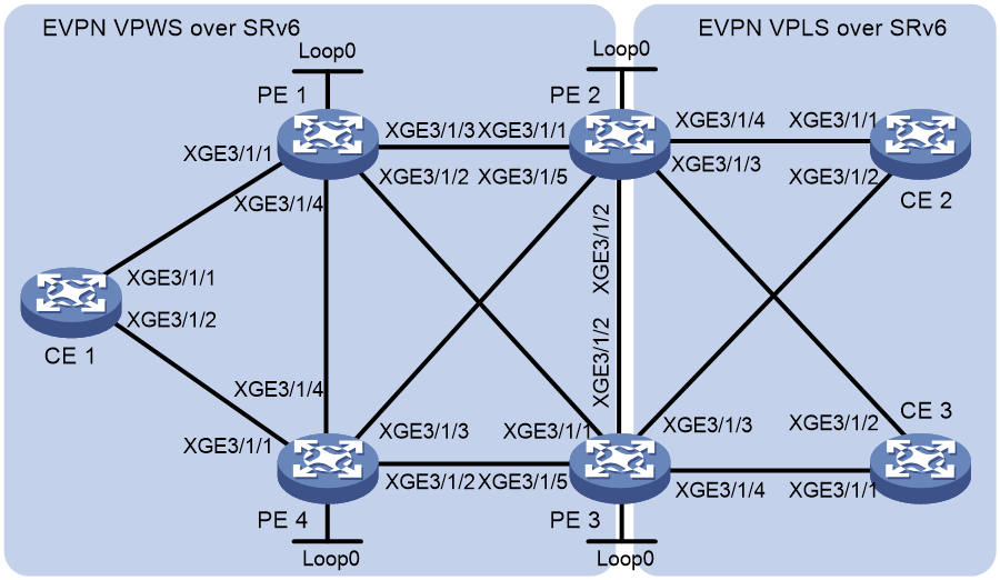
Table 1 Interface and IP address assignment
|
Device |
Interface |
IP address |
Device |
Interface |
IP address |
|
PE 1 |
Loop0 |
1::1/128 |
PE 4 |
Loop0 |
4::4/128 |
|
|
XGE3/1/1 |
- |
|
XGE3/1/1 |
- |
|
|
XGE3/1/2 |
10::1/64 |
|
XGE3/1/2 |
50::4/64 |
|
|
XGE3/1/3 |
20::1/64 |
|
XGE3/1/3 |
60::4/64 |
|
|
XGE3/1/4 |
40::1/64 |
|
XGE3/1/4 |
40::4/64 |
|
PE 2 |
Loop0 |
2::2/128 |
PE 3 |
Loop0 |
3::3/128 |
|
|
XGE3/1/1 |
20::2/64 |
|
XGE3/1/1 |
10::3/64 |
|
|
XGE3/1/2 |
30::2/64 |
|
XGE3/1/2 |
30::3/64 |
|
|
XGE3/1/3 |
- |
|
XGE3/1/3 |
- |
|
|
XGE3/1/4 |
- |
|
XGE3/1/4 |
- |
|
|
XGE3/1/5 |
60::2/64 |
|
XGE3/1/5 |
50::3/64 |
|
CE 1 |
RAGG1 |
100::1/64 |
CE 2 |
RAGG1 |
100::2/64 |
|
CE 3 |
RAGG1 |
100::3/64 |
|
|
|
Procedure
1. Configure CE 1:
# Create Layer 3 aggregate interface 1 and configure the aggregation group to operate in dynamic aggregation mode. Assign an IPv6 address and prefix length to the aggregate interface.
<CE1> system-view
[CE1] interface route-aggregation 1
[CE1-Route-Aggregation1] link-aggregation mode dynamic
[CE1-Route-Aggregation1] ipv6 address 100::1 64
[CE1-Route-Aggregation1] quit
# Assign interfaces Ten-GigabitEthernet 3/1/1 and Ten-GigabitEthernet 3/1/2 to aggregation group 1.
[CE1] interface ten-gigabitethernet 3/1/1
[CE1-Ten-GigabitEthernet3/1/1] port link-aggregation group 1
[CE1-Ten-GigabitEthernet3/1/1] quit
[CE1] interface ten-gigabitethernet 3/1/2
[CE1-Ten-GigabitEthernet3/1/2] port link-aggregation group 1
[CE1-Ten-GigabitEthernet3/1/2] quit
2. Configure PE 1:
# Run OSPFv3.
<PE1> system-view
[PE1] ospfv3
[PE1-ospfv3-1] router-id 1.1.1.1
[PE1-ospfv3-1] segment-routing ipv6 locator aaa
[PE1-ospfv3-1] area 0
[PE1-ospfv3-1-area-0.0.0.0] quit
[PE1-ospfv3-1] quit
# Configure Loopback 0.
[PE1] interface loopback 0
[PE1-LoopBack0] ipv6 address 1::1 128
[PE1-LoopBack0] ospfv3 1 area 0
[PE1-LoopBack0] quit
# Enable L2VPN.
[PE1] l2vpn enable
# Configure Ten-GigabitEthernet 3/1/2 (the interface connected to PE 3).
[PE1] interface ten-gigabitethernet 3/1/2
[PE1-Ten-GigabitEthernet3/1/2] ipv6 address 10::1 64
[PE1-Ten-GigabitEthernet3/1/2] ospfv3 1 area 0
[PE1-Ten-GigabitEthernet3/1/2] undo shutdown
[PE1-Ten-GigabitEthernet3/1/2] quit
# Configure Ten-GigabitEthernet 3/1/3 (the interface connected to PE 2).
[PE1] interface ten-gigabitethernet 3/1/3
[PE1-Ten-GigabitEthernet3/1/3] ipv6 address 20::1 64
[PE1-Ten-GigabitEthernet3/1/3] ospfv3 1 area 0
[PE1-Ten-GigabitEthernet3/1/3] undo shutdown
[PE1-Ten-GigabitEthernet3/1/3] quit
# Configure Ten-GigabitEthernet 3/1/4 (the interface connected to PE 4).
[PE1] interface ten-gigabitethernet 3/1/4
[PE1-Ten-GigabitEthernet3/1/4] ipv6 address 40::1 64
[PE1-Ten-GigabitEthernet3/1/4] ospfv3 1 area 0
[PE1-Ten-GigabitEthernet3/1/4] undo shutdown
[PE1-Ten-GigabitEthernet3/1/4] quit
# Configure PE 1 to establish IBGP connections with PE 2, PE 3, and PE 4, and use BGP EVPN to advertise route information.
[PE1] bgp 100
[PE1-bgp-default] router-id 1.1.1.1
[PE1-bgp-default] peer 2::2 as-number 100
[PE1-bgp-default] peer 2::2 connect-interface loopback 0
[PE1-bgp-default] peer 3::3 as-number 100
[PE1-bgp-default] peer 3::3 connect-interface loopback 0
[PE1-bgp-default] peer 4::4 as-number 100
[PE1-bgp-default] peer 4::4 connect-interface loopback 0
[PE1-bgp-default] address-family l2vpn evpn
[PE1-bgp-default-evpn] peer 2::2 enable
[PE1-bgp-default-evpn] peer 3::3 enable
[PE1-bgp-default-evpn] peer 4::4 enable
[PE1-bgp-default-evpn] peer 2::2 advertise encap-type srv6
[PE1-bgp-default-evpn] peer 3::3 advertise encap-type srv6
[PE1-bgp-default-evpn] peer 4::4 advertise encap-type srv6
[PE1-bgp-default-evpn] quit
[PE1-bgp-default] quit
# Assign an ESI to site-facing interface Ten-GigabitEthernet 3/1/1 and set the redundancy mode to all-active on the interface.
[PE1] interface ten-gigabitethernet 3/1/1
[PE1-Ten-GigabitEthernet3/1/1] esi 1.1.1.1.1
[PE1-Ten-GigabitEthernet3/1/1] evpn redundancy-mode all-active
[PE1-Ten-GigabitEthernet3/1/1] quit
# Create cross-connect group vpna and create an EVPN instance that uses SRv6 encapsulation for the cross-connect group. Configure an RD and route targets for the EVPN instance, enable SRv6 BE route recursion mode, and enable local FRR for the EVPN instance.
[PE1] xconnect-group vpna
[PE1-xcg-vpna] evpn encapsulation srv6
[PE1-xcg-vpna-evpn-srv6] route-distinguisher 1:1
[PE1-xcg-vpna-evpn-srv6] vpn-target 1:1 export-extcommunity
[PE1-xcg-vpna-evpn-srv6] vpn-target 1:1 import-extcommunity
[PE1-xcg-vpna-evpn-srv6] segment-routing ipv6 best-effort
[PE1-xcg-vpna-evpn-srv6] evpn frr local enable
[PE1-xcg-vpna-evpn-srv6] quit
# Create cross-connect pw1, associate interface Ten-GigabitEthernet 3/1/1 with the cross-connect. Create an SRv6 tunnel on the cross-connect for association between the AC and SRv6 tunnel.
[PE1-xcg-vpna] connection pw1
[PE1-xcg-vpna-pw1] ac interface ten-gigabitethernet 3/1/1
[PE1-xcg-vpna-pw1-Ten-GigabitEthernet3/1/1] quit
[PE1-xcg-vpna-pw1] evpn local-service-id 5001 remote-service-id 5000
[PE1-xcg-vpna-pw1-2-1] quit
# Apply locator aaa to cross-connect pw1.
[PE1-xcg-vpna-pw1] segment-routing ipv6 locator aaa
[PE1-xcg-vpna-pw1] quit
[PE1-xcg-vpna] quit
# Configure locator aaa for SRv6 SID allocation.
[PE1] segment-routing ipv6
[PE1-segment-routing-ipv6] encapsulation source-address 1::1
[PE1-segment-routing-ipv6] locator aaa ipv6-prefix 111:: 64 static 32
[PE1-segment-routing-ipv6-locator-aaa] quit
[PE1-segment-routing-ipv6] quit
3. Configure PE 2:
# Run OSPFv3.
<PE2> system-view
[PE2] ospfv3
[PE2-ospfv3-1] router-id 2.2.2.2
[PE2-ospfv3-1] segment-routing ipv6 locator aaa
[PE2-ospfv3-1] area 0.0.0.0
[PE2-ospfv3-1-area-0.0.0.0] quit
[PE2-ospfv3-1] quit
# Configure Loopback 0.
[PE2] interface loopback 0
[PE2-LoopBack0] ipv6 address 2::2 128
[PE2-LoopBack0] ospfv3 1 area 0
[PE2-LoopBack0] quit
# Enable L2VPN.
[PE2] l2vpn enable
# Configure Ten-GigabitEthernet 3/1/1 (the interface connected to PE 1).
[PE2] interface ten-gigabitethernet 3/1/1
[PE2-Ten-GigabitEthernet3/1/1] ipv6 address 20::2 64
[PE2-Ten-GigabitEthernet3/1/1] ospfv3 1 area 0
[PE2-Ten-GigabitEthernet3/1/1] undo shutdown
[PE2-Ten-GigabitEthernet3/1/1] quit
# Configure Ten-GigabitEthernet 3/1/2 (the interface connected to PE 3).
[PE2] interface ten-gigabitethernet 3/1/2
[PE2-Ten-GigabitEthernet3/1/2] ipv6 address 30::2 64
[PE2-Ten-GigabitEthernet3/1/2] ospfv3 1 area 0
[PE2-Ten-GigabitEthernet3/1/2] undo shutdown
[PE2-Ten-GigabitEthernet3/1/2] quit
# Configure Ten-GigabitEthernet 3/1/5 (the interface connected to PE 4).
[PE2] interface ten-gigabitethernet 3/1/5
[PE2-Ten-GigabitEthernet3/1/5] ipv6 address 60::2 64
[PE2-Ten-GigabitEthernet3/1/5] ospfv3 1 area 0
[PE2-Ten-GigabitEthernet3/1/5] undo shutdown
[PE2-Ten-GigabitEthernet3/1/5] quit
# Configure PE 2 to establish IBGP connections with PE 1, PE 3, and PE 4, and use BGP EVPN to advertise route information.
[PE2] bgp 100
[PE2-bgp-default] router-id 2.2.2.2
[PE2-bgp-default] peer 1::1 as-number 100
[PE2-bgp-default] peer 1::1 connect-interface loopback 0
[PE2-bgp-default] peer 3::3 as-number 100
[PE2-bgp-default] peer 3::3 connect-interface loopback 0
[PE2-bgp-default] peer 4::4 as-number 100
[PE2-bgp-default] peer 4::4 connect-interface loopback 0
[PE2-bgp-default] address-family l2vpn evpn
[PE2-bgp-default-evpn] peer 1::1 enable
[PE2-bgp-default-evpn] peer 3::3 enable
[PE2-bgp-default-evpn] peer 4::4 enable
[PE2-bgp-default-evpn] peer 1::1 advertise encap-type srv6
[PE2-bgp-default-evpn] peer 3::3 advertise encap-type srv6
[PE2-bgp-default-evpn] peer 4::4 advertise encap-type srv6
[PE2-bgp-default-evpn] quit
[PE2-bgp-default] quit
# Create VSI vpna and create an EVPN instance that uses SRv6 encapsulation for the VSI. Configure an RD and route targets for the EVPN instance, enable SRv6 BE route recursion mode, and apply a locator to the EVPN instance.
[PE2] vsi vpna
[PE2-vsi-vpna] esi 4.4.4.4.4
[PE2-vsi-vpna] evpn encapsulation srv6
[PE2-vsi-vpna-evpn-srv6] route-distinguisher 1:1
[PE2-vsi-vpna-evpn-srv6] vpn-target 1:1 export-extcommunity
[PE2-vsi-vpna-evpn-srv6] vpn-target 1:1 import-extcommunity
[PE2-vsi-vpna-evpn-srv6] segment-routing ipv6 best-effort
[PE2-vsi-vpna-evpn-srv6] segment-routing ipv6 locator aaa
# Create an SRv6 PW for intercommunication with the EVPN VPWS over SRv6 network for VSI vpna.
[PE2-vsi-vpna-evpn-srv6] evpn vpws local-service-id 5000 remote-service0id 5001 forwarding-preferred
[PE2-vsi-vpna-evpn-srv6] quit
[PE2-vsi-vpna] quit
# Assign an ESI to site-facing interface Ten-GigabitEthernet 3/1/3, set the redundancy mode to all-active on the interface, and map the interface to VSI vpna.
[PE2] interface ten-gigabitethernet 3/1/3
[PE2-Ten-GigabitEthernet3/1/3] esi 2.2.2.2.2
[PE2-Ten-GigabitEthernet3/1/3] evpn redundancy-mode all-active
[PE2-Ten-GigabitEthernet3/1/3] xconnect vsi vpna
[PE2-Ten-GigabitEthernet3/1/3] quit
# Assign an ESI to site-facing interface Ten-GigabitEthernet 3/1/4, set the redundancy mode to all-active on the interface, and map the interface to VSI vpna.
[PE2] interface ten-gigabitethernet 3/1/4
[PE2-Ten-GigabitEthernet3/1/4] esi 3.3.3.3.3
[PE2-Ten-GigabitEthernet3/1/4] evpn redundancy-mode all-active
[PE2-Ten-GigabitEthernet3/1/4] xconnect vsi vpna
[PE2-Ten-GigabitEthernet3/1/4] quit
# Configure locator aaa for SRv6 SID allocation.
[PE2] segment-routing ipv6
[PE2-segment-routing-ipv6] encapsulation source-address 2::2
[PE2-segment-routing-ipv6] locator aaa ipv6-prefix 222:: 64 static 32
[PE2-segment-routing-ipv6-locator-aaa] quit
[PE2-segment-routing-ipv6] quit
4. Configure PE 3:
# Run OSPFv3.
<PE3> system-view
[PE3] ospfv3
[PE3-ospfv3-1] router-id 3.3.3.3
[PE3-ospfv3-1] segment-routing ipv6 locator aaa
[PE3-ospfv3-1] area 0.0.0.0
[PE3-ospfv3-1-area-0.0.0.0] quit
[PE3-ospfv3-1] quit
# Configure Loopback 0.
[PE3] interface loopback 0
[PE3-LoopBack0] ipv6 address 3::3 128
[PE3-LoopBack0] ospfv3 1 area 0
[PE3-LoopBack0] quit
# Enable L2VPN.
[PE3] l2vpn enable
# Configure Ten-GigabitEthernet 3/1/1 (the interface connected to PE 1).
[PE3] interface ten-gigabitethernet 3/1/1
[PE3-Ten-GigabitEthernet3/1/1] ipv6 address 10::3 64
[PE3-Ten-GigabitEthernet3/1/1] ospfv3 1 area 0
[PE3-Ten-GigabitEthernet3/1/1] undo shutdown
[PE3-Ten-GigabitEthernet3/1/1] quit
# Configure Ten-GigabitEthernet 3/1/2 (the interface connected to PE 2).
[PE3] interface ten-gigabitethernet 3/1/2
[PE3-Ten-GigabitEthernet3/1/2] ipv6 address 30::3 64
[PE3-Ten-GigabitEthernet3/1/2] ospfv3 1 area 0
[PE3-Ten-GigabitEthernet3/1/2] undo shutdown
[PE3-Ten-GigabitEthernet3/1/2] quit
# Configure Ten-GigabitEthernet 3/1/5 (the interface connected to PE 4).
[PE3] interface ten-gigabitethernet 3/1/5
[PE3-Ten-GigabitEthernet3/1/5] ipv6 address 50::3 64
[PE3-Ten-GigabitEthernet3/1/5] ospfv3 1 area 0
[PE3-Ten-GigabitEthernet3/1/5] undo shutdown
[PE3-Ten-GigabitEthernet3/1/5] quit
# Configure PE 3 to establish IBGP connections with PE 1, PE 2, and PE 4, and use BGP EVPN to advertise route information.
[PE3] bgp 100
[PE3-bgp-default] router-id 3.3.3.3
[PE3-bgp-default] peer 1::1 as-number 100
[PE3-bgp-default] peer 1::1 connect-interface loopback 0
[PE3-bgp-default] peer 2::2 as-number 100
[PE3-bgp-default] peer 2::2 connect-interface loopback 0
[PE3-bgp-default] peer 4::4 as-number 100
[PE3-bgp-default] peer 4::4 connect-interface loopback 0
[PE3-bgp-default] address-family l2vpn evpn
[PE3-bgp-default-evpn] peer 1::1 enable
[PE3-bgp-default-evpn] peer 2::2 enable
[PE3-bgp-default-evpn] peer 4::4 enable
[PE3-bgp-default-evpn] peer 1::1 advertise encap-type srv6
[PE3-bgp-default-evpn] peer 2::2 advertise encap-type srv6
[PE3-bgp-default-evpn] peer 4::4 advertise encap-type srv6
[PE3-bgp-default-evpn] quit
[PE3-bgp-default] quit
# Create VSI vpna and create an EVPN instance that uses SRv6 encapsulation for the VSI. Configure an RD and route targets for the EVPN instance, enable SRv6 BE route recursion mode, and apply a locator to the EVPN instance.
[PE3] vsi vpna
[PE3-vsi-vpna] esi 4.4.4.4.4
[PE3-vsi-vpna] evpn encapsulation srv6
[PE3-vsi-vpna-evpn-srv6] route-distinguisher 1:1
[PE3-vsi-vpna-evpn-srv6] vpn-target 1:1 export-extcommunity
[PE3-vsi-vpna-evpn-srv6] vpn-target 1:1 import-extcommunity
[PE3-vsi-vpna-evpn-srv6] segment-routing ipv6 best-effort
[PE3-vsi-vpna-evpn-srv6] segment-routing ipv6 locator aaa
# Create an SRv6 PW for intercommunication with the EVPN VPWS over SRv6 network for VSI vpna.
[PE3-vsi-vpna-evpn-srv6] evpn vpws local-service-id 5000 remote-service0id 5001 forwarding-preferred
[PE3-vsi-vpna-evpn-srv6] quit
[PE3-vsi-vpna] quit
# Assign an ESI to site-facing interface Ten-GigabitEthernet 3/1/3, set the redundancy mode to all-active on the interface, and map the interface to VSI vpna.
[PE3] interface ten-gigabitethernet 3/1/3
[PE3-Ten-GigabitEthernet3/1/3] esi 2.2.2.2.2
[PE3-Ten-GigabitEthernet3/1/3] evpn redundancy-mode all-active
[PE3-Ten-GigabitEthernet3/1/3] xconnect vsi vpna
[PE3-Ten-GigabitEthernet3/1/3] quit
# Assign an ESI to site-facing interface Ten-GigabitEthernet 3/1/4, set the redundancy mode to all-active on the interface, and map the interface to VSI vpna.
[PE3] interface ten-gigabitethernet 3/1/4
[PE3-Ten-GigabitEthernet3/1/4] esi 3.3.3.3.3
[PE3-Ten-GigabitEthernet3/1/4] evpn redundancy-mode all-active
[PE3-Ten-GigabitEthernet3/1/4] xconnect vsi vpna
[PE3-Ten-GigabitEthernet3/1/4] quit
# Configure locator aaa for SRv6 SID allocation.
[PE3] segment-routing ipv6
[PE3-segment-routing-ipv6] encapsulation source-address 3::3
[PE3-segment-routing-ipv6] locator aaa ipv6-prefix 333:: 64 static 32
[PE3-segment-routing-ipv6-locator-aaa] quit
[PE3-segment-routing-ipv6] quit
5. Configure PE 4:
# Run OSPFv3.
<PE4> system-view
[PE4] ospfv3
[PE4-ospfv3-1] router-id 4.4.4.4
[PE4-ospfv3-1] segment-routing ipv6 locator aaa
[PE4-ospfv3-1] area 0
[PE4-ospfv3-1-area-0.0.0.0] quit
[PE4-ospfv3-1] quit
# Configure Loopback 0.
[PE4] interface loopback 0
[PE4-LoopBack0] ipv6 address 4::4 128
[PE4-LoopBack0] ospfv3 1 area 0
[PE4-LoopBack0] quit
# Enable L2VPN.
[PE4] l2vpn enable
# Configure Ten-GigabitEthernet 3/1/2 (the interface connected to PE 3).
[PE4] interface ten-gigabitethernet 3/1/2
[PE4-Ten-GigabitEthernet3/1/2] ipv6 address 50::4 64
[PE4-Ten-GigabitEthernet3/1/2] ospfv3 1 area 0
[PE4-Ten-GigabitEthernet3/1/2] undo shutdown
[PE4-Ten-GigabitEthernet3/1/2] quit
# Configure Ten-GigabitEthernet 3/1/3 (the interface connected to PE 2).
[PE4] interface ten-gigabitethernet 3/1/3
[PE4-Ten-GigabitEthernet3/1/3] ipv6 address 60::4 64
[PE4-Ten-GigabitEthernet3/1/3] ospfv3 1 area 0
[PE4-Ten-GigabitEthernet3/1/3] undo shutdown
[PE4-Ten-GigabitEthernet3/1/3] quit
# Configure Ten-GigabitEthernet 3/1/4 (the interface connected to PE 1).
[PE4] interface ten-gigabitethernet 3/1/4
[PE4-Ten-GigabitEthernet3/1/4] ipv6 address 40::4 64
[PE4-Ten-GigabitEthernet3/1/4] ospfv3 1 area 0
[PE4-Ten-GigabitEthernet3/1/4] undo shutdown
[PE4-Ten-GigabitEthernet3/1/4] quit
# Configure PE 4 to establish IBGP connections with PE 1, PE 2, and PE 3, and use BGP EVPN to advertise route information.
[PE4] bgp 100
[PE4-bgp-default] router-id 4.4.4.4
[PE4-bgp-default] peer 1::1 as-number 100
[PE4-bgp-default] peer 1::1 connect-interface loopback 0
[PE4-bgp-default] peer 2::2 as-number 100
[PE4-bgp-default] peer 2::2 connect-interface loopback 0
[PE4-bgp-default] peer 3::3 as-number 100
[PE4-bgp-default] peer 3::3 connect-interface loopback 0
[PE4-bgp-default] address-family l2vpn evpn
[PE4-bgp-default-evpn] peer 1::1 enable
[PE4-bgp-default-evpn] peer 2::2 enable
[PE4-bgp-default-evpn] peer 3::3 enable
[PE4-bgp-default-evpn] peer 4::4 advertise encap-type srv6
[PE4-bgp-default-evpn] peer 1::1 advertise encap-type srv6
[PE4-bgp-default-evpn] peer 3::3 advertise encap-type srv6
[PE4-bgp-default-evpn] quit
[PE4-bgp-default] quit
# Assign an ESI to site-facing interface Ten-GigabitEthernet 3/1/1 and set the redundancy mode to all-active on the interface.
[PE4] interface ten-gigabitethernet 3/1/1
[PE4-Ten-GigabitEthernet3/1/1] esi 1.1.1.1.1
[PE4-Ten-GigabitEthernet3/1/1] evpn redundancy-mode all-active
[PE4-Ten-GigabitEthernet3/1/1] quit
# Create cross-connect group vpna and create an EVPN instance that uses SRv6 encapsulation for the EVPN instance. Configure an RD and route targets for the EVPN instance, enable SRv6 BE route recursion mode, and enable local FRR for the EVPN instance.
[PE4] xconnect-group vpna
[PE4-xcg-vpna] evpn encapsulation srv6
[PE4-xcg-vpna-evpn-srv6] route-distinguisher 1:1
[PE4-xcg-vpna-evpn-srv6] vpn-target 1:1 export-extcommunity
[PE4-xcg-vpna-evpn-srv6] vpn-target 1:1 import-extcommunity
[PE4-xcg-vpna-evpn-srv6] segment-routing ipv6 best-effort
[PE4-xcg-vpna-evpn-srv6] evpn frr local enable
[PE4-xcg-vpna-evpn-srv6] quit
# Create cross-connect pw1, associate interface Ten-GigabitEthernet 3/1/1 with the cross-connect. Create an SRv6 tunnel on the cross-connect for association between the AC and SRv6 tunnel.
[PE4-xcg-vpna] connection pw1
[PE4-xcg-vpna-pw1] ac interface ten-gigabitethernet 3/1/1
[PE4-xcg-vpna-pw1-Ten-GigabitEthernet3/1/1] quit
[PE4-xcg-vpna-pw1] evpn local-service-id 5001 remote-service-id 5000
[PE4-xcg-vpna-pw1-2-1] quit
# Apply locator aaa to cross-connect pw1.
[PE4-xcg-vpna-pw1] segment-routing ipv6 locator aaa
[PE4-xcg-vpna-pw1] quit
[PE4-xcg-vpna] quit
# Configure locator aaa for SRv6 SID allocation.
[PE4] segment-routing ipv6
[PE4-segment-routing-ipv6] encapsulation source-address 4::4
[PE4-segment-routing-ipv6] locator aaa ipv6-prefix 444:: 64 static 32
[PE4-segment-routing-ipv6-locator-aaa] quit
[PE4-segment-routing-ipv6] quit
6. Configure CE 2:
# Create Layer 3 aggregate interface 1 and configure the aggregation group to operate in dynamic aggregation mode. Assign an IPv6 address and prefix length to the aggregate interface.
<CE2> system-view
[CE2] interface route-aggregation 1
[CE2-Route-Aggregation1] link-aggregation mode dynamic
[CE2-Route-Aggregation1] ipv6 address 100::2 64
[CE2-Route-Aggregation1] quit
# Assign interfaces Ten-GigabitEthernet 3/1/1 and Ten-GigabitEthernet 3/1/2 to aggregation group 1.
[CE2] interface ten-gigabitethernet 3/1/1
[CE2-Ten-GigabitEthernet3/1/1] port link-aggregation group 1
[CE2-Ten-GigabitEthernet3/1/1] quit
[CE2] interface ten-gigabitethernet 3/1/2
[CE2-Ten-GigabitEthernet3/1/2] port link-aggregation group 1
[CE2-Ten-GigabitEthernet3/1/2] quit
7. Configure CE 3:
# Create Layer 3 aggregate interface 1 and configure the aggregation group to operate in dynamic aggregation mode. Assign an IPv6 address and prefix length to the aggregate interface.
<CE3> system-view
[CE3] interface route-aggregation 1
[CE3-Route-Aggregation1] link-aggregation mode dynamic
[CE3-Route-Aggregation1] ipv6 address 100::3 64
[CE3-Route-Aggregation1] quit
# Assign interfaces Ten-GigabitEthernet 3/1/1 and Ten-GigabitEthernet 3/1/2 to aggregation group 1.
[CE3] interface ten-gigabitethernet 3/1/1
[CE3-Ten-GigabitEthernet3/1/1] port link-aggregation group 1
[CE3-Ten-GigabitEthernet3/1/1] quit
[CE3] interface ten-gigabitethernet 3/1/2
[CE3-Ten-GigabitEthernet3/1/2] port link-aggregation group 1
[CE3-Ten-GigabitEthernet3/1/2] quit
Verifying the configuration
# On PE 1, display L2VPN SRv6 information. Verify that PE 1 has established SRv6 tunnels with PE 2 and PE 3 and the two SRv6 tunnels are ECMP tunnels for load sharing.
[PE1] display l2vpn peer srv6
Total number of SRv6 Tunnels: 2
2 up, 0 blocked, 0 down, 0 defect
Xconnect-group Name: vpna
Peer : 2::2
Flag : ECMP
State : Up
Remote SrvID : 5000
Peer : 3::3
Flag : ECMP
State : Up
Remote SrvID : 5000
# On PE 1, display SRv6 forwarding information.
[PE1] display l2vpn forwarding srv6
Total number of cross-connections: 1
Total number of SRv6 tunnels: 2, 2 up, 0 blocked, 0 down
Xconnect-group Name : vpna
Connection Name : pw1
Link ID : 0x1 Type: BE State: Up
In SID : 111::1:0:2
Out SID : 222::1:0:3
Link ID : 0x1 Type: BE State: Up
In SID : 111::1:0:2
Out SID : 333::1:0:3
# Verify that CE 1 and CE 2 can ping each other and CE 1 and CE 3 can ping each other. (Details not shown.)
