- Table of Contents
-
- 11-Segment Routing Configuration Guide
- 00-Preface
- 01-SR-MPLS configuration
- 02-SR-MPLS TE policy configuration
- 03-SRv6 configuration
- 04-SRv6 TE policy configuration
- 05-SRv6 VPN overview
- 06-IP L3VPN over SRv6 configuration
- 07-EVPN L3VPN over SRv6 configuration
- 08-EVPN VPWS over SRv6 configuration
- 09-EVPN VPLS over SRv6 configuration
- 10-Public network IP over SRv6 configuration
- 11-SRv6 OAM configuration
- 12-SRv6 network slicing configuration
- Related Documents
-
| Title | Size | Download |
|---|---|---|
| 01-SR-MPLS configuration | 1.97 MB |
Traffic steering to an SR-MPLS tunnel
Dynamic SID allocation through an IGP
Dynamic SID allocation through BGP
SID allocation through BGP EPE
Label forwarding entry installation based on SIDs
BGP SR and non-SR network interworking
Microloop avoidance after a network failure
Microloop avoidance after a failure recovery
Restrictions and guidelines for SR-MPLS
IP traffic forwarding over SRLSPs tasks at a glance
MPLS TE traffic forwarding over static SRLSPs tasks at a glance
MPLS TE traffic forwarding over explicit paths tasks at a glance
MPLS TE traffic forwarding over PCE-calculated SRLSPs tasks at a glance
Prerequisites for static segment configuration
Configuring a static adjacency segment
Configuring a static prefix segment
Configuring IGP-based SID advertisement
IGP-based prefix SID advertisement tasks at a glance
IGP-based adjacency SID advertisement tasks at a glance (for non-member interfaces)
IGP-based adjacency SID advertisement tasks at a glance (for member interfaces)
Prerequisites for configuring IGP-based SID advertisement
Configuring the IGP to support SR-MPLS
Enabling SR-MPLS adjacency SID allocation for the IGP
Assigning adjacency SIDs to aggregation group member interfaces
Configuring BGP-based SID advertisement
BGP-based SID advertisement tasks at a glance
Prerequisites for configuring BGP-based SID advertisement
Configuring BGP to support SR-MPLS
Specifying the type of label to advertise to the penultimate hop
Configuring SID allocation through BGP EPE
Configuring a BGP EPE peer set
Configuring delay advertisement for BGP EPE
Configuring bandwidth advertisement for BGP EPE
Configuring the SRLSP establishment triggering policy
Configuring the device to prefer SRLSPs in traffic forwarding
Configuring an MPLS TE tunnel over a static SRLSP
Binding a static SRLSP to an MPLS TE tunnel interface
Configuring an MPLS TE tunnel over an explicit-path SRLSP
Configuring an explicit path for the MPLS TE tunnel
Configuring an MPLS TE tunnel over the explicit path
Configuring an MPLS TE tunnel over a PCE-calculated SRLSP
Configuring an MPLS TE tunnel interface to use PCE to calculate the SRLSP
Configuring IGP SR and LDP interworking
Restrictions and guidelines for IGP SR and LDP interworking
Prerequisites for SR-MPLS and LDP internetworking
Enabling advertisement of locally configured prefix-SID mappings
Configuring prefix-SID mappings
Enabling reception of advertised prefix-SID mappings
Configuring BGP SR and non-SR network interworking
Restrictions and guidelines for BGP SR and non-SR network interworking
Restrictions and guidelines for TI-LFA FRR
Disabling an interface from participating in TI-LFA calculation
Configuring microloop avoidance
Configuring SR microloop avoidance to encapsulate only strict SIDs in the SID list
Configuring tunnel BFD for all SRLSPs
Display and maintenance commands for SR-MPLS
SR-MPLS configuration examples
Example: Configuring SR-MPLS based on static segments
Example: Configuring SR-MPLS based on ISIS-advertised SIDs
Example: Configuring SR-MPLS based on OSPF-advertised SIDs
Example: Configuring an SR-based MPLS TE tunnel over an explicit path
Example: Configuring an MPLS TE tunnel over a PCE-calculated SRLSP
Example: Configuring SR-MPLS inter-AS option B
Example: Configuring SR-MPLS to LDP (IS-IS)
Example: Configuring SR-MPLS to LDP (OSPF)
Example: Configuring SR-MPLS to LDP (labeled route exchange in BGP IPv4 unicast address family)
Example: Configuring SR-MPLS over LDP
Example: Configuring IS-IS TI-LFA FRR
Configuring SR-MPLS
About SR-MPLS
Segment Routing (SR) is a source routing technology. The source node selects a path for the packets, and then encodes the path in the packet header as an ordered list of segments. Each segment is identified by a label called the segment identifier (SID). The SR nodes along the path forward the packets based on the SIDs in the packets. Only the source node needs to maintain the path status.
SR can operate with MPLS. In an MPLS network, SR uses MPLS labels as SIDs to forward packets on an LSP.
SR-MPLS characteristics
SR-MPLS has the following characteristics:
· SR-MPLS forwards packets based on the existing MPLS infrastructure. No infrastructure modifications are needed to implement SR on an MPLS network. For more information about the MPLS infrastructure, see MPLS basics configuration in MPLS Configuration Guide.
· SR-MPLS expands and optimizes existing IGPs and BGP and uses the IGPs and BGP to distribute labels.
· SR-MPLS implements network features such as MPLS TE in a simpler way, eliminating issues such as heavy and complicated routing protocol deployment.
Basic concepts
· SR node—A node enabled with the SR-MPLS feature. The ingress node (source node) adds labels to packets. The transit nodes forward packets based on labels. The egress node removes labels and forwards packets to the destination networks. SR nodes form an SR domain.
· Segment—An instruction an SR node executes on the incoming packet.
· SID—Segment ID, which is MPLS label in SR-MPLS.
· Segment type—The following types of segments are available:
¡ Prefix segment—SIDs are assigned to nodes based on destination address prefix. The nodes create prefix-specific forwarding entries.
¡ Adjacency segment—SIDs are assigned to nodes based on adjacency.
· SRLSP—Segment routing label switched path, an LSP along which SR uses MPLS labels as SIDs to forward packets.
· SRGB—Segment routing global block, a range of global labels dedicated for SR-MPLS prefix SIDs. Different nodes can have different SRGBs. The minimum label value of an SRGB label range is referred to as the base value of the SRGB.
· SRLB—Segment routing local block, a range of local labels dedicated for SR-MPLS adjacency SIDs. All nodes share the same SRLB. The minimum label value of the SRLB label range is referred to as the base value of the SRLB.
· MPLS Segment Routing Best Effort (SR-MPLS BE)—Uses IGP to compute the optimal SRLSP by using the shortest path algorithm, and uses SIDs to instruct data forwarding. The SRLSP establishment and data forwarding are similar to the LDP LSP establishment and data forwarding. SR-MPLS BE does not use tunnel interfaces.
· MPLS Segment Routing Traffic Engineering (SR-MPLS TE)—A TE tunnel technology that uses SR as the control protocol. SR-MPLS BE and SR-MPLS TE both need to establish SRLSPs, but the ways they establish SRLSPs are different. An SRLSP used by an SR-MPLS TE tunnel can be established manually through explicit path configuration. Or, it can be computed by the controller, which then deploys the label stack to the device for establishment of the SRLSP. The tunnel interface must be created on the ingress node of the SR-MPLS TE tunnel. The device encapsulates the label stack into the packets so as to control the forwarding path of the packets on the network.
How SR-MPLS works
SR-MPLS involves the following steps:
1. Label allocation for all nodes and links along the packet forwarding paths.
Available methods include static segment configuration and dynamic SID allocation.
2. Label forwarding entry installation based on SIDs.
All SR-MPLS devices in the SR domain use the allocated labels to create label forwarding entries.
3. SRLSP setup.
You can manually configure SRLSPs, or use an IGP, BGP, or a controller to dynamically create SRLSPs.
When the ingress node of an SRLSP receives a packet, it adds labels to the packet and forwards the packet to the egress node through the SRLSP. After receiving a packet from the SRLSP, the egress node removes the label and forwards the packet based on the routing table.
You can bind a higher layer application (for example, MPLS TE) to an SRLSP to forward traffic of the application through the SRLSP.
Traffic steering to an SR-MPLS tunnel
SR-MPLS tunnels include SR-MPLS BE tunnels and SR-MPLS TE tunnels.
After an SR-MPLS BE or SR-MPLS TE tunnel is established, traffic cannot be forwarded automatically through the tunnel. You can use the following methods to steer traffic to an SR-MPLS BE or SR-MPLS TE tunnel:
Static route
The static route method is a simple, direct method for steering traffic to an SR-MPLS TE tunnel.
This method configures a static route destined for the destination address through the tunnel interface and allows the static route to recurse to LSP tunnels established by SR-MPLS TE. For more information about static route recursion to LSP tunnels, see static route configuration in Layer 3—IP Routing Configuration Guide.
Tunnel policy
When traffic of a VPN is forwarded through a tunnel, the traffic is forwarded through an LDP LSP tunnel by default. To direct the traffic to an SR-MPLS BE or SR-MPLS TE tunnel, you can apply a tunnel policy or tunnel selector to the VPN.
Based on the service requirements, you can configure one of the following types of tunnel policy to direct traffic of a VPN to an SR-MPLS BE or SR-MPLS TE tunnel:
· Tunnel binding—Bind a destination IP address to a tunnel in a tunnel policy. After the tunnel policy is applied to a VPN, the VPN traffic to the destination IP address will be forwarded by the bound tunnel.
· Preferred tunnel—Specify an SR-MPLS TE tunnel as a preferred tunnel in a tunnel policy. After the tunnel policy is applied to a VPN, the VPN traffic will be forwarded by the preferred tunnel. This method explicitly specifies a tunnel for a VPN, facilitating traffic planning.
· Load sharing—Specify the tunnel types (SR-MPLS BE or SR-MPLS TE tunnels) and selection order and the number of tunnels for load sharing in a tunnel policy.
For more information about tunnel policies, see MPLS Configuration Guide.
PBR
The policy-based routing (PBR) method defines a PBR policy to specify the output interface for packets that match an ACL as an SR-MPLS TE tunnel interface, and then applies the PBR policy to the incoming interface of packets. In this way, traffic is redirected to the SR-MPLS TE tunnel.
The PBR method can match the packets to be forwarded by a tunnel interface by packet destination IP address, source IP address, and protocol type. Compared with the static route method, the PBR method is more flexible but its configuration is more complicated. For more information about PBR, see policy-based routing configuration in Layer 3—IP Routing Configuration Guide.
Automatic route advertisement
Automatic route advertisement distributes the SR-MPLS TE tunnel to the IGP (OSPF or IS-IS), so the SR-MPLS TE tunnel can participate in IGP routing calculation.
Automatic route advertisement can be implemented by using the following methods:
· IGP shortcut—Also known as AutoRoute Announce. It considers the SR-MPLS TE tunnel as a link that directly connects the tunnel ingress node (source node) and the egress node (endpoint node). Only the ingress node uses the SR-MPLS TE tunnel during IGP route calculation.
· Forwarding adjacency—Considers the SR-MPLS TE tunnel as a link that directly connects the tunnel ingress node and the egress node, and advertises the link to the network through an IGP. Every node in the network uses the SR-MPLS TE tunnel during IGP route calculation.
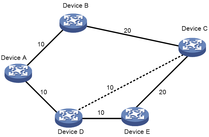
As shown in Figure 1, an SR-MPLS TE tunnel exists from Device D to Device C. IGP shortcut enables only the ingress node Device D to use the SR-MPLS TE tunnel in the IGP route calculation. Device A cannot use this tunnel to reach Device C. With forwarding adjacency enabled, Device A can learn this SR-MPLS TE tunnel and transfer traffic to Device C by forwarding the traffic to Device D.
Figure 1 IGP shortcut and forwarding adjacency
Static segment configuration
Static SR-MPLS provides the following methods for configuring static segments for a destination:
· Prefix segment method—Manually configure the incoming label, outgoing label, and next hop for the destination address prefix on each SR node.
· Adjacency segment method—Manually configure the incoming label and next hop for the adjacency to the neighbor on each SR node.
Dynamic SID allocation through an IGP
SR-MPLS expands IGP protocols such as IS-IS and OSPF to advertise SIDs in IGP protocol packets. SR-MPLS provides the following methods for dynamically allocating and advertising SIDs:
· Prefix SID.
· Adjacency SID.
Prefix SID
After you configure an SID for the loopback address on each SR node, the SIDs uniquely identify the SR nodes. All SR nodes in the SR domain use an IGP to advertise their own prefix SIDs. After receiving advertised prefix SIDs, each SR node calculates the prefix SIDs to the advertisers.
The prefix SID advertisement can be one of the following types:
· Absolute value advertisement—Each SR node advertises the prefix SID absolute value and the SRGB.
· Index value advertisement—Each SR node advertises the prefix SID index and the SRGB.
Each SR node is assigned a globally unique index value for the node's prefix. The prefix SID an SR node allocates to a prefix equals the SRGB base of the SR node plus the index for that prefix.
|
|
NOTE: The device supports only the index value advertisement in the current software release. |
Adjacency SID
SR nodes use an IGP to advertise SIDs allocated to the IGP adjacencies (that is, the links to its IGP neighbors). The SIDs are used to identify the links.
The adjacency SIDs can be allocated automatically or manually.
· Automatic adjacency SID allocation—SR nodes allocate labels in SRLBs to the IGP adjacencies as SIDs.
· Manual adjacency SID allocation—You can assign adjacency SID by using absolute values or index values. If you use index values, the adjacency SID of a link is the base value of the SRLB plus the index value for the link.
Dynamic SID allocation through BGP
SR-MPLS expands BGP to advertise prefix SIDs in BGP protocol packets. BGP uses routing policies to assign SIDs to prefixes when redistributing routes. The SIDs uniquely identify the SR nodes. All SR nodes in the SR domain use BGP to advertise their own prefix SIDs, including the SIDs and SID index values. From received advertisement packets, each SR node derives the prefix SIDs for the advertisers.
BGP prefix SIDs can be exchanged between BGP peers only through IPv4 unicast routes.
Dynamic SID allocation through BGP applies to MPLS VPN inter-AS option C networks.
SID allocation through BGP EPE
The BGP Egress Peer Engineering (BGP EPE) feature assigns BGP peering SIDs to segments across ASs. The device sends BGP peering SIDs to the controller through BGP-LS extensions. The controller orchestrates IGP SIDs and BGP peering SIDs for inter-AS forwarding over optimal paths.
You can manually specify the BGP peering SIDs to be assigned to the BGP peers or peer groups or let the device randomly assign these SIDs.
BGP EPE supports the following types of BGP peering SIDs:
· PeerNode SID—Identifies a peer node. Each BGP session is assigned a PeerNode SID. An EBGP peer session established based on a loopback interface might use multiple physical links. The PeerNode SID for the EBGP peer therefore might have multiple outgoing interfaces. The device will load-share traffic among these outgoing interfaces when it forwards the traffic based on the PeerNode SID.
· PeerAdj SID—Identifies an adjacency to a peer. An EBGP peer session established based on a loopback interface might use multiple physical links. Each physical link will be assigned a PeerAdj SID. The device forwards traffic through a specific outgoing interface when it forwards the traffic based on a PeerAdj SID.
· PeerNode-Adj SID—Identifies a peer node or one or multiple adjacencies to a peer.
· PeerSet SID—Identifies a set of peers. BGP EPE supports adding a group of peers to a set and assigning the set a PeerSet SID. The device will load-share traffic among the peers in the set when it forwards the traffic based on a PeerSet SID. A PeerSet SID identifies the set of which PeerNode SIDs or PeerAdj SIDs are members.
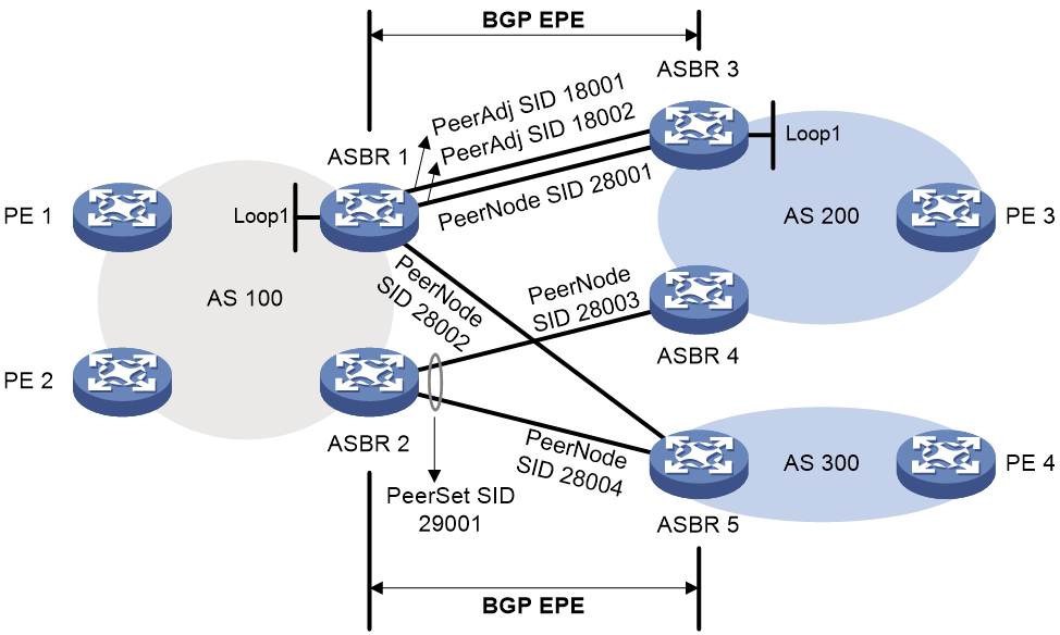
As shown in Figure 2, BGP EPE allocates SID labels as follows:
· ASBR 1 and ASBR 3 are directly connected through two physical links. The two ASBRs establish an EBGP peer relationship with each other through loopback interfaces. BGP EPE assigns PeerNode SID 28001 to the peer node and assigns PeerAdj SIDs 18001 and 18002 to the two physical links. Traffic between the two ASBRs will be load-shared on the two physical links when it is forwarded based on the PeerNode SID.
· An EBGP peer relationship is established over a physical link between ASBR 1 and ASBR 5, ASBR 2 and ASBR 4, and ASBR 2 and ASBR 5. BGP EPE only assigns labels (PeerNode SIDs 28002, 28003, and 28004) to the peer nodes.
· ASBR 4 and ASBR 5 both establish an EBGP peer relationship with ASBR 2. BGP EPE adds ASBR 4 and ASBR 5 to a BGP EPE peer set and assigns the set PeerSet SID 29001. Traffic will be sent to the devices in the peer set for load sharing when it is forwarded based on the PeerSet SID.
SIDs that BGP EPE assigns are locally significant. These SIDs are not advertised to other devices and are not affected by route types exchanged between BGP peers.
SID allocation through BGP EPE is typically used for MPLS VPN inter-AS option B.
Label forwarding entry installation based on SIDs
Label forwarding entry installation based on IGP prefix SIDs
Label forwarding entries based on prefix SIDs can be static or dynamic.
· Static label forwarding entries—The device creates local label forwarding entries based on manually configured incoming labels, outgoing labels, and next hops.
· Dynamic label forwarding entries—The device uses the IGP to flood in the SR domain the local SRGB and the index of the prefix SID for the local loopback interface. Based on the flooded information, the other devices in the domain calculates their local label forwarding entries by using the following rules:
¡ Incoming label = Local SRGB base value + Index
¡ Outgoing label = SRGB base value of the next hop + Index
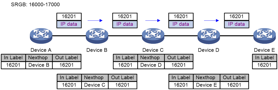
Figure 3 Creating label forwarding entries based on IGP prefix SIDs
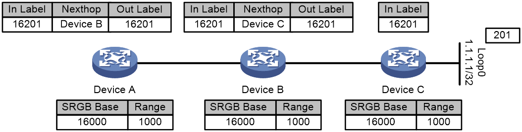
Figure 3 shows how dynamic label forwarding entries are created. After you assign index value 201 to loopback address 1.1.1.1/32 on Device C, Device C uses an IGP packet to advertise the index value and its local SRGB. Then, the devices calculate incoming and outgoing labels according to the previously mentioned label calculation rules.
· Devices C calculates its incoming label, which is 16201.
· Device B calculates its incoming label and outgoing label and creates a label forwarding entry. The incoming label is 16201. The outgoing label is 16201. The next hop is Device C.
· Device A calculates its incoming label and outgoing label and creates a label forwarding entry. The incoming label is 16201. The outgoing label is 16201. The next hop is Device B.
Label forwarding entry installation based on BGP prefix SIDs
The device redistributes routes to BGP and assigns prefix SIDs to redistributed routes based on routing policies. Then, the device uses BGP to flood in the SR domain the prefix SIDs and the indexes of the prefix SIDs. Based on the flooded information, the other devices in the domain calculates their local label forwarding entries by using the following rules:
· Incoming label = Local SRGB base value + Index
· Outgoing label = Received SID
Figure 4 Creating label forwarding entries based on BGP prefix SIDs
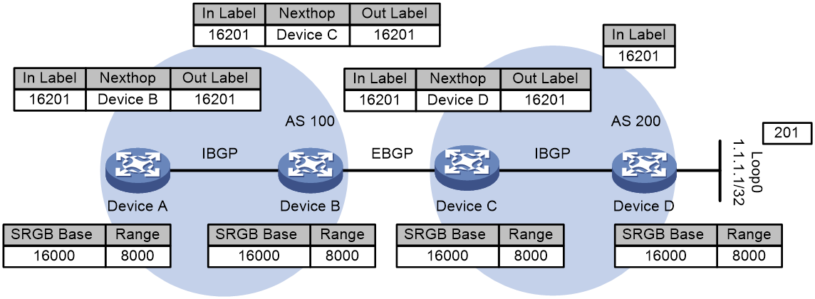
Figure 4 shows how label forwarding entries are created. After you assign index value 201 to loopback address 1.1.1.1/32 on Device D, Device D redistributes the route of the address and assigns it an SID (16201 in this example). Then, the device uses a BGP packet to advertise the SID and index value. The devices in the SR domain calculate incoming and outgoing labels according to the previously mentioned label calculation rules and create label forwarding entries.
· Devices D calculates its incoming label, which is 16201.
· Device C calculates its incoming label and outgoing label and creates a label forwarding entry. The incoming label is 16201. The outgoing label is 16201. The next hop is Device D.
· Device B calculates its incoming label and outgoing label and creates a label forwarding entry. The incoming label is 16201. The outgoing label is 16201. The next hop is Device C.
· Device A calculates its incoming label and outgoing label and creates a label forwarding entry. The incoming label is 16201. The outgoing label is 16201. The next hop is Device B.
Label forwarding entry installation based on BGP EPE
Configure BGP EPE on border routers to assign SIDs to specific peers or peer groups.
Figure 5 Creating label forwarding entries by using BGP EPE
As shown in Figure 5, you can configure BGP EPE on Device B to assign BGP peering SIDs to EBGP neighbors Device C and Device D. BGP peering SIDs are locally significant and are not advertised to neighbors.
Label forwarding entry installation based on adjacency SIDs
When using adjacency SIDs, each device allocates a static or dynamic incoming label to the link to its neighbor. The label has local significance. Multiple devices can use the same adjacency SID.
Figure 6 Creating label forwarding entries based on adjacency SIDs
As shown in Figure 6, the devices are running the same IGP. After IGP adjacencies are established between the devices, Device A, Device B, and Device C allocates labels and creates label forwarding entries as follows:
· Device A allocates label 203 to the link to its neighbor Device B.
· Device B allocates label 202 to the link to its neighbor Device C.
· Device C allocates label 201 to the link to its neighbor Device D.
· Device A creates a label forwarding entry with incoming label 203 and next hop Device B.
· Device B creates a label forwarding entry with incoming label 202 and next hop Device C.
· Device C creates a label forwarding entry with incoming label 201 and next hop Device D.
SRLSP setup
You can use the following methods to create SRLSPs:
· Manually configure an SRLSP.
To configure an SRLSP, you must specify the label stack for packets to be forwarded along the SRLSP on the ingress node. Each label in the stack corresponds to a prefix SID or adjacency SID. The system can look for the outgoing label and next hop based on the prefix SID or adjacency SID.
· Configure SR nodes to use BGP or an IGP to dynamically establish an SRLSP.
SR nodes follow these steps to establish SRLSPs:
a. Use BGP or an IGP to collect prefix SID information from the SR-MPLS network.
b. Calculate the shortest paths to other SR nodes based on the collected prefix SID information and the BGP or IGP network topology.
c. Establish SRLSPs based on the shortest paths.
· Configure a controller to deploy SRLSP configuration to the device so the device creates SRLSPs.
For more information about controller configuration, see the user guide for the controller.
Packet forwarding in SR-MPLS
Based on the SID allocation method, SR-MPLS uses one of the following packet forwarding methods:
· Prefix SID-based packet forwarding—The ingress node encapsulates the prefix SID for the egress node to a packet. The transit nodes forward the packet based on label forwarding entries.
· Adjacency SID-based packet forwarding—The ingress node encapsulates the label stack that contains the adjacency SIDs of all links along the forwarding path to a packet. Each transit node uses the top label in the label stack to determine the next hop and pops the top label before forwarding the packet to the next hop.
· Prefix and adjacency SID-based packet forwarding—The nodes use prefix SID-based packet forwarding in combination with adjacency-based packet forwarding.
Prefix SID-based packet forwarding within the same AS
Figure 7 shows how a packet is forwarded along the SRLSP from Device A to Device E based on prefix SIDs. In this example, the outgoing label for the packet is 16201 on Device A.
1. Ingress node Device A searches for a forwarding entry for label 16201, adds outgoing label 16201 to the packet and sends the packet to the next hop (Device B).
2. When transit node Device B receives the packet, it searches for a label forwarding entry that matches the label in the packet. Then, Device B uses the outgoing label of the matched entry (16201) to replace the label in the packet and forwards the packet to the next hop (Device C).
3. Transit nodes Device C and Device D process the packet in the same way Device B does.
4. When egress node Device E receives the packet, it removes the label and forwards the packet by IP address.
Figure 7 Prefix SID-based packet forwarding within the same AS
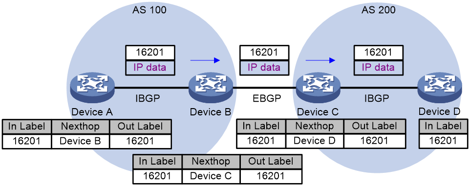
Prefix SID-based packet forwarding across ASs
Figure 8 shows how a packet is forwarded along the SRLSP from Device A to Device D based on prefix SIDs. In this example, the outgoing label for the packet is 16201 on Device A.
1. Ingress node Device A searches for a forwarding entry for label 16201, adds outgoing label 16201 to the packet, and sends the packet to the next hop (Device B).
2. When transit node Device B receives the packet, it searches for a label forwarding entry that matches the label in the packet (16201). Then, Device B uses the outgoing label of the matched entry (16201) to replace the label in the packet and forwards the packet to the next hop (Device C).
3. Transit nodes Device C processes the packet in the same way Device B does.
4. When egress node Device D receives the packet, it removes the label and forwards the packet by IP address.
Figure 8 Prefix SID-based packet forwarding across ASs
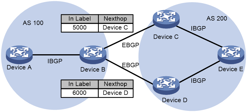
BGP EPE-based packet forwarding across ASs
As shown in Figure 9, you can configure BGP EPE and an SRLSP used for the MPLS TE tunnel on Device B to steer packets to travel through Device C or Device D to Device E. In this example, packets travel from Device A through Device B and Device D to Device E. Device B uses BGP EPE to assign SID 6000 to Device D. A static SRLSP is established between Device B and Device D for the MPLS TE tunnel and Device B also assigns SID 6000 to the SRLSP.
1. Within AS 100, source node Device A adds label 16204 to the packet according to the SRLSP, and sends the packet to Device B.
2. When Device B receives the packet, it searches for a label forwarding entry and finds that it should forward the packet through the MPLS TE tunnel. Then, Device B removes label 16204 from the packet, and forwards the packet through the MPLS TE tunnel to Device D.
3. Within AS 200, Device D searches for a label forwarding entry based on the SRLSP, adds label 16201 to the packet, and sends the packet to Device E.
4. When egress node Device E receives the packet, it removes label 16201 and forwards the packet by IP address.
Figure 9 BGP EPE-based packet forwarding across ASs
Adjacency SID-based packet forwarding
Figure 10 shows how a packet is forwarded along the SRLSP from Device A to Device E based on adjacency SIDs. In this example, the label stack for the packet is configured as (200, 201, 202, and 203) on Device A.
1. Ingress node Device A searches for a forwarding entry for the top label (200) to determine the next hop. Then, Device A adds label stack (201, 202, and 203) to the packet, and forwards the packet to the next hop (Device B).
2. When transit node Device B receives the packet, it searches for a forwarding entry for the top label (201) to determine the next hop. Then, Device B removes the top label from the stack and forwards the packet to the next hop (Device C).
3. When transit node Device C receives the packet, it searches for a forwarding entry for the top label (202) to determine the next hop. Then, Device C removes the top label from the stack and forwards the packet to the next hop (Device D).
4. When transit node Device D receives the packet, it searches for a forwarding entry for the label (203) to determine the next hop. Then, Device D removes the label stack from the packet and forwards the packet to the next hop (Device E).
5. When egress node Device E receives the packet, it forwards the packet by IP address.
Figure 10 Adjacency SID-based packet forwarding
Prefix and adjacency SID-based packet forwarding
Figure 11 shows how a packet is forwarded along the SRLSP from Device A to Device E based on prefix SIDs and adjacency SIDs. In this example, the index value for the prefix SID of Device C is 1. The prefix SIDs for Device A, Device B, and Device C are all 16001. The Adjacency SIDs that Device C and Device D allocate to the adjacencies are 16 and 17, respectively. On Device A, the label stack for the packet is (16001, 16, 17).
1. Ingress node Device A searches for a forwarding entry for label 16001 to determine the outgoing label (16001) and next hop (Device B). Device A adds label stack (16001, 16, 17) to the packet and sends the packet to the next hop (Device B).
2. When transit node Device B receives the packet, it searches for a label forwarding entry that matches the top label in the label stack (16001). Then, Device B uses the outgoing label of the matched entry (16001) to replace the top label and forwards the packet to the next hop (Device C).
3. When transit node Device C receives the packet, it removes the top label 16001 and searches for a forwarding entry for the next label (16) to determine the next hop. Then, Device C removes label 16 from the stack and forwards the packet to the next hop (Device D).
4. When transit node Device D receives the packet, it searches for a forwarding entry for the label (17) to determine the next hop. Then, Device D removes the label stack from the packet and forwards the packet to the next hop (Device E).
5. When egress node Device E receives the packet, it forwards the packet by IP address.
Figure 11 Prefix and adjacency SID-based packet forwarding
IGP SR and LDP interworking
IGP SR and LDP interworking enables SR-MPLS networks that use an IGP for SID advertisement to communicate and cooperate with MPLS LDP networks.
IGP SR and LDP interworking supports the following modes:
· SR to LDP—Maps prefixes on an LDP network to SR-MPLS SIDs to forward traffic from an SR-MPLS network to an MPLS LDP network.
· LDP to SR—Uses an IGP protocol to advertise SIDs and associates SIDs with LDP labels to forward traffic from an MPLS LDP network to an SR-MPLS network.
· SR over LDP—Enables SR-MPLS networks to communicate through an LDP network.
SR to LDP
The SR to LDP mode defines the following roles:
· Segment Routing Mapping Server (SRMS)—Advertises prefix-SID mappings on behalf of SR-incapable devices (LDP devices). You must configure prefix-SID mappings on the SRMS.
· Segment Routing Mapping Client (SRMC)—Receives prefix-SID mappings advertised by the SRMS and creates SR-MPLS label forwarding entries.
As shown in Figure 12, Device A and Device B are running SR-MPLS, and Device B, Device C, and Device D are running LDP. After Device D assigns a label for destination address 3.3.3.3/32, Device B and Device C each install an LDP label forwarding entry.
The following steps establish a mapping between the SRLSP and the LDP LSP:
1. Device B acts as an SRMS. It assigns SID index value 201 to the IP address of loopback interface 0 on Device D (3.3.3.3/32), and then advertises an IP prefix-SID mapping TLV to Device A.
2. Device A acts as an SRMC. After receiving the advertised mapping TLV, it creates an SR-MPLS label forwarding entry.
A mapping is established between the SRLSP and the LDP LSP.
Figure 12 SR to LDP packet forwarding
If Device A uses an SRLSP to send a packet to Device D, the packet is forwarded as follows:
1. Ingress node Device A adds label 16201 to the packet and then sends the packet to transit node Device B.
2. When transit node Device B receives the packet, it searches for a label forwarding entry that matches incoming label 16201. Because the entry does not have an outgoing label, Device B searches for a valid LDP outgoing label for destination address 3.3.3.3/32. Then, Device B adds the LDP label (20) to the packet as the SR outgoing label and forwards the packet to the next hop (Device C).
3. When transit node Device C receives the packet, it searches for an LDP label forwarding entry for incoming label 20. Then, it removes the label from the packet and forwards the packet to egress node Device D.
4. The egress node forwards the packet by IP address.
LDP to SR
As shown in Figure 13, Device C and Device D are running SR-MPLS, and Device A, Device B, and Device C are running LDP. Each device running LDP assigns a label to destination address 3.3.3.3/32 and then installs an LDP label forwarding entry.
The following steps establish an association between the SR-MPLS label and the LDP label:
1. After you assign SID index value 201 to the IP address of loopback interface 0 on Device D (3.3.3.3/32), Device D sends an IGP protocol packet to advertise the index value and the local SRGB.
2. After receiving the packet, Device C creates an SR-MPLS label forwarding entry.
The SR-MPLS label and the LDP label are associated on Device C.
Figure 13 LDP to SR packet forwarding
A packet from Device A to Device D is forwarded as follows:
1. Ingress node Device A adds an LDP label (20) to the packet and forwards the packets to the next hop (Device B).
2. Device B searches for an LDP label forwarding entry, uses 30 as the outgoing label, and forwards the packet to the next hop (Device C).
3. Device C searches for an LDP label forwarding entry for incoming label 30 and finds no outgoing label. Because valid SR-MPLS outgoing label 16201 exists for the destination address 3.3.3.3.32, Device C uses the label (16201) as the outgoing label and forwards the packet to Device D.
4. Egress node Device D deletes label 16201 from the packet and forwards the packet by IP address.
SR over LDP
For SR-MPLS networks to communicate across an LDP network, the SR/LDP border devices must be able to connect the SR LSP and the LDP LSP as follows:
· SR-MPLS to LDP interworking—The border device installs SR-to-LDP label forwarding entries. For a packet from the SR-MPLS network to the LDP network, the SR-MPLS label forwarding entry on the border device does not have an outgoing label. The border device uses the outgoing label of the LDP label forwarding entry for the same destination address as the outgoing label of the packet.
· LDP to SR-MPLS interworking—The border device installs LDP-to-SR label forwarding entries. For a packet from the LDP network to the SR-MPLS network, the LDP forwarding entry on the border device does not have an outgoing label. The border device must use the outgoing label of the SR-MPLS forwarding entry for the same destination address as the outgoing label of the packet.
As shown in Figure 14, Device A, Device B, Device D, and Device E are running SR-MPLS. After you assign index value 201 to loopback interface address 3.3.3.3/32 on Device E, Device E will advertise the index value and the local SRGB. After Device A, Device B, and Device D receive the message, they will install their respective SR-MPLS label forwarding entries. Device B, Device C, and Device D are running LDP. They allocate labels to destination address 3.3.3.3/32 to generate the LDP label forwarding entries.
A packet that Device A sends to Device E will be forwarded as follows:
1. Ingress node Device A encapsulates label 16201 to the packet and forwards the packet to transit node Device B.
2. Transit node Device B searches for an SR-MPLS label forwarding entry for incoming label 16201 and finds that the entry does not have an outgoing label. Because an LDP label forwarding entry with outgoing label 20 exists for the destination address (3.3.3.3/32), Device B encapsulates outgoing label 20 in the packet. Then Device B sends the packet to transit node Device C.
3. Device C forwards the packet to Device D based on its LDP label forwarding entries. The outgoing label is 30.
4. Device D searches for an LDP label forwarding entry for incoming label 30 and finds that the entry does not have an outgoing label. Because an SR-MPLS label forwarding entry with outgoing label 16201 exists for the destination address (3.3.3.3/32), Device B encapsulates outgoing label 16201 in the packet. Then Device D sends the packet to egress node Device E.
5. Egress node Device E deletes the incoming label and forwards the packet by IP address.
BGP SR and non-SR network interworking
In an inter-AS networking scenario, an SR-MPLS network that uses BGP to advertise SR labels can communicate with a network that uses BGP to advertise non-SR labels. On the non-SR network, the outer tunnel protocol (public tunnel protocol) of a BGP label can be RSVP-TE, GRE, or LDP. The following uses LDP as an example to describe the interworking mechanism:
BGP SR and LDP interworking enables SR-MPLS networks that use BGP for SID advertisement to interoperate with MPLS LDP networks.
To support BGP SR and LDP interworking, the edge device on the LDP network must support SR to assign SIDs to SR-incapable devices on the LDP network, and maps the SIDs to MPLS labels. Therefore, BGP SR and LDP interworking defines the following roles:
· Segment Routing Mapping Server (SRMS)—Advertises SIDs on the SR network on behalf of SR-incapable devices (LDP devices), and advertises prefix-SID mappings to the SRMC. You must configure prefix-SID mappings on the SRMS.
· Segment Routing Mapping Client (SRMC)—Receives prefix-SID mappings advertised by the SRMS and creates SR-MPLS label forwarding entries.
BGP SR and LDP interworking involves the following communication processes:
· SR to LDP—Uses BGP to map the prefixes on an LDP network to the SIDs on an SR network to forward traffic from the SR network to the LDP network.
· LDP to SR—Uses BGP to advertise SIDs and associates SIDs with the BGP requested labels to forward traffic from an LDP network to an SR network.
SR to LDP
When the device uses BGP to implement SR to LDP, it assigns SIDs to the SR-incapable devices in the LDP network according to the locally configured prefix-SID mappings. A node enabled with both SR-MPLS and LDP must act as both an SRMS and an SRMC.
As shown in Figure 15, Device B, Device C, and Device D are running LDP. Device A and Device B are running BGP-based SR-MPLS. The label advertisement is as follows:
1. Device C and Device D assigns labels 20 and 3 (implicit null label) to the destination address 3.3.3.3/32, respectively. Device B, Device C, and Device D each install an LDP label forwarding entry.
2. Device D advertises the BGP route 3.3.3.3/32 with label 1274 to Device B. Label 1274 is requested by BGP. The next hop is Device D.
3. Acting as an SRMS, Device B assigns SID index value 201 to the IP address of loopback interface 0 on Device D (3.3.3.3/32).
4. Acting as an SRMC, Device B installs an SR label forwarding entry based on the locally configured prefix-SID mapping. Device B establishes a mapping between the SRLSP and the LDP LSP. That is, on Device B, the incoming label is the SR-MPLS label 16201 and the outgoing label is the BGP requested label 1274 in the label forwarding entry for 3.3.3.3/32.
5. Device B advertises the prefix SID for 3.3.3.3/32 to Device A through BGP packets. Device A installs an SR label forwarding entry based on the received BGP packets.
Figure 15 BGP SR to LDP packet forwarding
A packet from Device A to Device D is forwarded as follows:
1. Ingress node Device A adds label 16201 to the packet and then sends the packet to transit node Device B.
2. When transit node Device B receives the packet, it searches for an SR label forwarding entry that matches incoming label 16201. The entry does not have an outgoing label. Device B has a valid BGP outgoing label (1274) for destination address 3.3.3.3/32 with Device D as the next hop. Then, Device B replaces the SR-MPLS label 16201 with the BGP outgoing label (1274) in the packet to be sent to Device D through the LDP LSP. Thus Device B encapsulates the outer label 20 for the packet, and forwards the packet to the next hop (Device C).
3. When Device C receives the packet, it searches for an LDP label forwarding entry that matches incoming label 20 to get the outgoing label 3, which is the implicit null label. Then, Device C removes the outer label from the packet (as defined by PHP) and forwards the packet to egress node Device D.
4. The egress node Device D removes the inner label 1274 and then forwards the packet by IP address.
LDP to SR
As shown in Figure 16, Device C and Device D are running SR-MPLS, and Device A, Device B, and Device C are running LDP. The label advertisement process is as follows:
1. Device A and Device B assigns labels 20 and 3 (implicit null label) to Device C. Device A and Device B each install an LDP label forwarding entry.
2. The administrator assigns SID index value 201 to the IP address of loopback interface 0 on Device D (3.3.3.3/32). Device D and Device C establish an EBGP neighbor relationship, and Device D uses BGP to advertise the index value to Device C.
3. After receiving the packet, Device C installs an SR label forwarding entry for 3.3.3.3/32.
4. Device C requests label 1280 for 3.3.3.3/32 and advertises the route 3.3.3.3/32 with label 1280 to its IBGP neighbor Device A.
5. The SR label and the BGP label are associated on Device C.
Figure 16 LDP to BGP SR packet forwarding
A packet from Device A to Device D is forwarded as follows:
1. Device A adds label 1280 to the packet, and the next hop is Device C. Device A needs to use an LDP LSP to reach Device C. So, Device A adds an outer label 20 to the packet and forwards the packets to the next hop Device B.
2. Device B searches for an LDP label forwarding entry that matches incoming label 20 to get the outgoing label 3, which is the implicit null label. Then, Device B removes the outer label 20 (as defined by PHP) from the packet and forwards the packet to the next hop (Device C).
3. Device C receives the packet with label 1280. It replaces the label 1280 with label 16201 according to the SR label and the BGP label association, and then sends the packet to the egress node Device D.
4. Egress node Device D removes label 16201 from the packet and forwards the packet by IP address.
TI-LFA FRR
Topology-Independent Loop-Free Alternate Fast Re-Route (TI-LFA FRR) provides link and node protection. When a link or node fails, TI-LFA FRR switches the traffic to the backup path to ensure continuous data forwarding.
TI-LFA FRR advantages
SR-based TI-LFA FRR has the following advantages:
· It satisfies the basic requirements for IP FRR fast convergence.
· Traffic protection is not affected by the network environment.
· The algorithm is not too complicated.
· It uses the converged route as the backup path. All devices have finished route convergence before the forward process begins.
TI-LFA FRR concepts
· P space—Use the source node of the protected link as the root to establish a shortest path tree. All nodes that are reachable from the source node without passing the protected link form the P space. Nodes in the P space are called P nodes.
· Extended P space—Use the source node of the protected link and its neighbors as the roots to establish shortest path trees. All nodes that are reachable from the source node or one of its neighbors without passing the protected link form the extended P space. The P space is a subset of the extended P space.
· Q space—Use the destination node of the protected link as the root to establish a reverse shortest path tree. All nodes that are reachable from the root node without passing the protected link form the Q space. Nodes in the Q space are called Q nodes.
· TI-LFA algorithm—In real networks, the P space and Q space do not have common nodes or directly connected nodes. The device cannot calculate the backup path and cannot meet the high availability requirement. The TI-LFA algorithm can calculate the extended P space, Q space, converged shortest path tree, repair list, and backup output interface for the protected link to get the backup next hop.
· Repair list—A constraint path used to indicate how a P node reaches a Q node when the P space and Q space do not have common nodes. The repair list contains the following labels (SIDs):
¡ Labels of P nodes.
¡ Adjacency SIDs from P nodes to Q nodes.
TI-LFA FRR path calculation
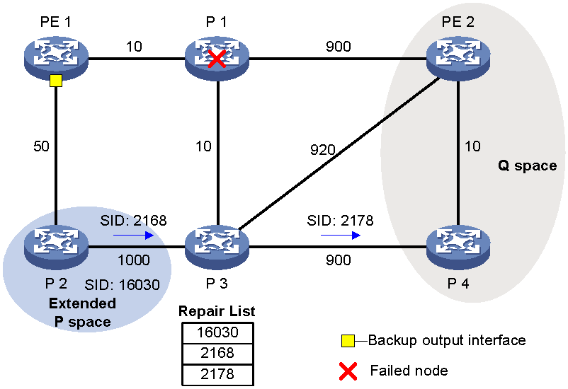
As shown in Figure 17, PE 1 is the source node. P 1 is the faulty node. PE 2 is the destination node. The numbers on links represent the link costs. A data flow traverses PE 1, P 1, and PE 2. To protect data against P 1 failure, TI-LFA FRR calculates the extended P space, Q space, shortest path tree converged after P 1 fails, repair list, and backup output interface, and creates the backup forwarding entry.
TI-LFA FRR calculates the backup path by using the following steps:
1. Calculates the extended P space: P 2.
2. Calculates the Q space: PE 2 and P 4.
3. Calculates the shortest path tree converged after P 1 fails: PE 1 --> P 2 --> P 4 --> PE 2.
4. Calculates the repair list: Node label of P 2 (16030), adjacency SID of P 2 to P 3 (2168), and adjacency SID of P 3 to P 4 (2178).
5. Calculates the backup output interface, that is, the output interface to the next hop after the link from PE 1 to P 1 fails.
TI-LFA FRR forwarding process
After TI-LFA FRR finishes backup path calculation, traffic will be switched to the backup path in response to a primary path failure.
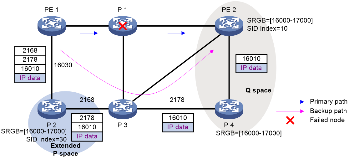
As shown in Figure 18, P 2 is a P node and P 4 is a Q node. When the next hop on the primary path (P 1) fails, TI-LFA FRR switches the traffic to the backup path. The following are the detailed steps:
1. PE 1 encapsulates a label stack to a packet according to the repair list. The labels, from the outmost to inmost, are as follows:
¡ Node label of P node P 2 (16030), which equals the SRGB base value of PE 1 (nexthop of the P node) plus the SID index value of P 2.
¡ Adjacency SIDs from P node P 2 to Q node P 4, which are 2168 and 2178.
¡ The destination's node label 16010, which equals the SRGB base value of Q node P 4 plus the SID index value of destination node PE 2.
2. P2 receives the packet, searches for a label forwarding entry based on the outmost label, pops label 2168, and forwards the packet to P 3.
3. P3 receives the packet, searches for a label forwarding entry based on the outmost label, pops label 2178, and forwards the packet to P 4.
4. P4 receives the packet, and searches for a label forwarding entry based on the outmost label. Because the outgoing label is 16010 and the next hop is PE 2, P 4 encapsulates 16010 as the outmost label and forwards the packet to PE 2.
Figure 18 Data forwarding over the TI-LFA FRR backup path
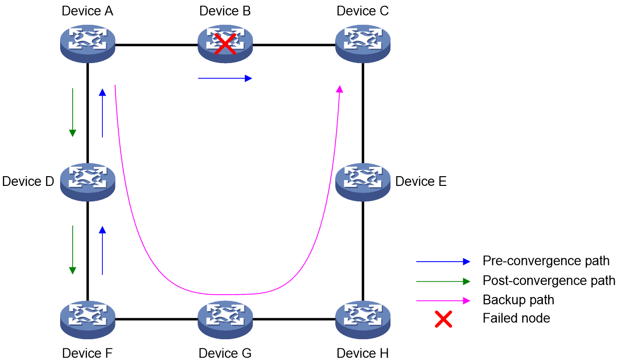
Microloop avoidance after a network failure
As shown in Figure 19, when Device B fails, traffic to Device C will be switched to the backup path calculated by TI-LFA. After Device A finishes route convergence, traffic will be switched to the post-convergence path. If Device D and Device F have not finished route convergence and still forward traffic along the pre-convergence path, a loop is formed between Device A and Device F. The loop exists until Device D and Device F finish route convergence.
FRR microloop avoidance and SR microloop avoidance can resolve this issue. After you configure TI-LFA, Device A first switches traffic to the backup path calculated by TI-LFA when Device B fails. Then, Device A waits for Device D and Device F to finish route convergence before starting route convergence. After Device A also finishes route convergence, Device A switches the traffic to the converged route.
Figure 19 Diagram for microloop avoidance after a network failure
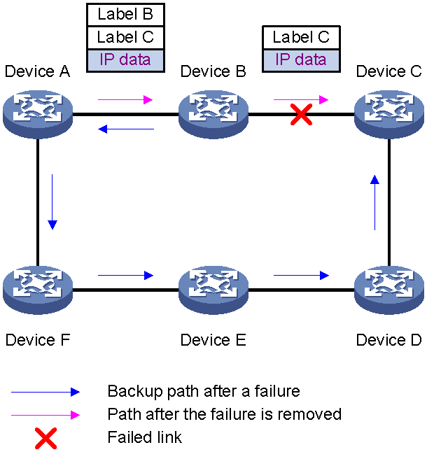
Microloop avoidance after a failure recovery
As shown in Figure 20, before the link between Device B and Device C recovers, traffic traverses along the backup path. After the link recovers, Device A will forward the traffic to Device B if Device A finishes route convergence before Device B. Before Device B also finishes route convergence, Device B still forwards the traffic along the backup path. A loop is formed between Device A and Device B.
SR microloop avoidance can resolve this issue. After the link recovers, SR microloop avoidance automatically calculates the optimal path from Device A to Device C and forwards traffic along the path. To forward a packet along the newly calculated path, Device A adds, for example, the adjacency SID from Device B to Device C to the packet and then sends the packet to Device B. Then, Device B forwards the packet to Device C based on the path information.
When the microloop avoidance RIB-update-delay timer expires, Device B should have finished route convergence. Device A does not add path information to packets anymore, and it forwards packets to Device C as usual.
Figure 20 Diagram for microloop avoidance after a failure recovery
Protocols and standards
· draft-bashandy-rtgwg-segment-routing-ti-lfa-04
· draft-ietf-spring-segment-routing-mpls-00
· draft-ietf-spring-segment-routing-02
· draft-ietf-isis-segment-routing-extensions-06
· draft-ietf-spring-segment-routing-11
· draft-ietf-ospf-segment-routing-extensions-17
· 3draft-ietf-idr-bgpls-segment-routing-epe-15
· draft-ietf-idr-bgp-prefix-sid-19
· RFC 7684, OSPFv2 Prefix/Link Attribute Advertisement
· RFC 7752, North-Bound Distribution of Link-State and Traffic Engineering (TE) Information Using BGP
· RFC 8402:Segment Routing Architecture
Restrictions and guidelines for SR-MPLS
For BGP-based SR, the SRGB range is fixed (16000 through 24000). To use both BGP and an IGP to advertise prefix SIDs, set the SRGB range for MPLS to 16000 through 24000.
SR-MPLS tasks at a glance
IP traffic forwarding over SRLSPs tasks at a glance
To forward IP traffic over SRLSPs, perform the following configuration tasks:
1. Configuring segments
Select one of the following tasks:
¡ Configuring IGP-based SID advertisement
2. (Optional.) Configuring the SRLSP establishment triggering policy
3. (Optional.) Configuring the device to prefer SRLSPs in traffic forwarding
4. (Optional.) Configuring SR-MPLS and LDP interworking
¡ Configuring IGP SR and LDP interworking
¡ Configuring BGP SR and non-SR network interworking
5. (Optional.) Configuring TI-LFA FRR
6. (Optional.) Configuring SR OAM
MPLS TE traffic forwarding over static SRLSPs tasks at a glance
To forward MPLS TE traffic over static SRLSPs, perform the following configuration tasks:
1. Configuring segments
Select one of the following tasks:
¡ Configuring IGP-based SID advertisement
¡ Configuring BGP-based SID advertisement
2. Configuring an MPLS TE tunnel over a static SRLSP
3. (Optional.) Configuring SR-MPLS and LDP interworking
¡ Configuring IGP SR and LDP interworking
¡ Configuring BGP SR and non-SR network interworking
4. (Optional.) Configuring TI-LFA FRR
5. (Optional.) Configuring SR OAM
MPLS TE traffic forwarding over explicit paths tasks at a glance
To forward MPLS TE traffic over explicit paths, perform the following configuration tasks:
1. Configuring IGP-based SID advertisement
2. Configuring an MPLS TE tunnel over an explicit-path SRLSP
3. (Optional.) Configuring SR-MPLS and LDP interworking
¡ Configuring IGP SR and LDP interworking
¡ Configuring BGP SR and non-SR network interworking
4. (Optional.) Configuring TI-LFA FRR
5. (Optional.) Configuring SR OAM
MPLS TE traffic forwarding over PCE-calculated SRLSPs tasks at a glance
To forward MPLS TE traffic over PCE-calculated SRLSPs, perform the following configuration tasks:
1. Configuring an MPLS TE tunnel over a PCE-calculated SRLSP
2. (Optional.) Configuring SR-MPLS and LDP interworking
¡ Configuring IGP SR and LDP interworking
¡ Configuring BGP SR and non-SR network interworking
3. (Optional.) Configuring TI-LFA FRR
4. (Optional.) Configuring SR OAM
Configuring MPLS SRGBs
Restrictions and guidelines
The global MPLS SRGB is used for prefix segments and BGP prefix SIDs. If no MPLS SRGB is configured for a protocol process, the process uses the global MPLS SRGB.
If you have configured prefix SIDs when you configure an SRGB, the SRGB must contain the configured prefix SIDs.
In the following situations, a configured SRGB takes effect after a device reboot:
· The SRGB contains a label that is already used by another protocol. For example, the SRGB contains a label that is already used by LDP.
· The SRGB overlaps with the label range of another protocol. For example, the SRGB for OSPF process 1 overlaps with the SRGB for IS-IS process 1.
Before executing this command, use the display mpls label command to display MPLS label usage information. Make sure that all labels in the specified SRGB range are idle. If a label in the range is not idle, the SRGB cannot be configured.
Configuring the global MPLS SRGB
1. Enter system view.
system-view
2. Enter segment routing view.
segment-routing
3. Configure the global MPLS SRGB.
global-block minimum-value maximum-value
The global MPLS SRGB is from 16000 to 24000.
Configuring the MPLS SRGB for IS-IS
1. Enter system view.
system-view
2. Enter IS-IS view.
isis process-id
3. Configure the MPLS SRGB.
segment-routing global-block minimum-value maximum-value
The MPLS SRGB for IS-IS is from 16000 to 24000.
Configuring the MPLS SRGB for OSPF
1. Enter system view.
system-view
2. Enter OSPF view.
ospf process-id
3. Configure the MPLS SRGB.
segment-routing global-block minimum-value maximum-value
By default, the MPLS SRGB for OSPF is from 16000 to 24000.
Configuring the MPLS SRLB
About this task
The segment routing local block (SRLB) is the range of local labels dedicated for SR-MPLS adjacency SIDs.
Restrictions and guidelines
|
|
CAUTION: With the ignore-conflict keyword specified, the local-block command can be executed but does not take effect if an allocated SR-MPLS adjacency SID is not within the configured SRLB range. To make the configured SRLB take effect, you must restart the device. Meanwhile, you must also change the allocated SID to be within the SRLB. Otherwise, the SRLSP using that SID cannot forward packets normally. |
Before configuring the MPLS SRLB, use the display mpls label command to display MPLS label usage information. Make sure that all labels in the specified SRLB range are idle. If a label in the range is not idle, the MPLS SRLB cannot be configured. For more information about the display mpls label command, see MPLS Command Reference.
Procedure
1. Enter system view.
system-view
2. Enter segment routing view.
segment-routing
3. Configure the MPLS SRLB.
local-block minimum-value maximum-value [ ignore-conflict ]
The MPLS SRLB is from 15000 to 15999.
Configuring static segments
Prerequisites for static segment configuration
Before you configure static segments for a static SRLSP, perform the following tasks:
· Determine the ingress node, transit nodes, and egress node of the static SRLSP.
· Determine the incoming label for the adjacency segment from a node to next hop of the node. Determine the incoming label of the prefix segment for the destination IP address on each node. On a device, a static SRLSP, a static LSP, and a static CRLSP cannot use the same incoming label. For more information about CRLSP, see MPLS TE configuration in MPLS Configuration Guide.
· Enable MPLS on all nodes and interfaces that will participate in MPLS forwarding. For information about enabling MPLS, see basic MPLS configuration in MPLS Configuration Guide.
Configuring a static adjacency segment
Restrictions and guidelines
This task is required on all nodes of a static SRLSP.
Multiple static SRLSPs can share an adjacency segment.
If you specify the next hop address for a static adjacency segment, make sure the following requirements are met:
· The device has a route to the next hop address.
· MPLS is enabled on the output interface of the route.
If you specify an output interface for a static adjacency segment, make sure the following requirements are met:
· The interface is up.
· The interface can receive direct routes.
· MPLS is enabled on the interface.
A static adjacency segment must use a different incoming label than existing static LSPs, static PWs, and static CRLSPs. If not, the configured adjacency segment is unavailable. The adjacency segment cannot become available even if you change the incoming label of the static LSP, static PW, or static CRLSP. To resolve this problem, you must delete the existing adjacency segment and configure a new one with a different incoming label.
Procedure
1. Enter system view.
system-view
2. Configure a static adjacency segment.
static-sr-mpls adjacency adjacency-path-name in-label label-value { nexthop ip-address | outgoing-interface interface-type interface-number }
The next hop address for a static adjacency segment cannot be a local public IP address.
Configuring a static prefix segment
Restrictions and guidelines
This task is required on all nodes of a static SRLSP.
Multiple static SRLSPs to the same destination can share a prefix segment.
A prefix segment must use the next hop or output interface of the optimal route (non-BGP route) to the destination address of the prefix segment. You can configure multiple prefix segments to the destination address for load sharing if the optimal route has more than one next hop or output interface. To avoid configuration failure, make sure all prefix segments use the same prefix segment name and incoming label.
Procedure
1. Enter system view.
system-view
2. Configure a static prefix segment.
static-sr-mpls prefix prefix-path-name destination ip-address { mask-length | mask } in-label in-label-value [ { nexthop ip-address | outgoing-interface interface-type interface-number } out-label out-label-value ]
The next hop address for a static prefix segment cannot be a local public IP address.
Configuring IGP-based SID advertisement
IGP-based prefix SID advertisement tasks at a glance
Perform the following tasks on each node along an SRLSP:
1. Configuring the IGP to support
IGP-based adjacency SID advertisement tasks at a glance (for non-member interfaces)
Perform the following tasks on each node along an SRLSP:
1. Configuring the IGP to support
2. Enabling SR-MPLS adjacency SID allocation for the IGP
3. (Optional.) Assigning adjacency SIDs
You can assign adjacency SIDs to adjacencies manually.
IGP-based adjacency SID advertisement tasks at a glance (for member interfaces)
Perform the following tasks on each node along an SRLSP:
1. Configuring the IGP to support
Prerequisites for configuring IGP-based SID advertisement
Before you configure IGP-based SID advertisement, perform the following tasks:
· Determine the ingress node, transit nodes, and egress node of an SRLSP.
· Determine the SIDs, MPLS SRGBs, and MPLS SRLBs for nodes.
· Enable MPLS on all nodes and interfaces that will participate in MPLS forwarding. For information about enabling MPLS, see basic MPLS configuration in MPLS Configuration Guide.
Configuring the IGP to support SR-MPLS
Prerequisites
For SR-MPLS to take effect, perform the following tasks before configuring the IGP to support SR-MPLS:
· If the IGP is IS-IS, set the cost style to wide, compatible, or wide-compatible. For more information about the cost style, see IS-IS configuration in Layer 3—IP Routing Configuration Guide.
· If the IGP is OSPF, enable opaque LSA reception and advertisement capability. For more information about the capability, see OSPF configuration in Layer 3—IP Routing Configuration Guide.
Configuring IS-IS to support SR-MPLS
1. Enter system view.
system-view
2. Enter IS-IS view.
isis process-id
3. Enter IS-IS IPv4 unicast address family view.
address-family ipv4
4. Enable SR-MPLS.
segment-routing mpls
By default, SR-MPLS is disabled.
Configuring OSPF to support SR-MPLS
1. Enter system view.
system-view
2. Enter OSPF view.
ospf process-id
3. Enable SR-MPLS.
segment-routing mpls
By default, SR-MPLS is disabled.
Configuring prefix SIDs
About this task
Configuring a prefix SID in loopback interface view binds the SID with the IP address of the loopback interface.
To configure a prefix SID, use one of the following methods:
· Specify an absolute value. The absolute value is used as the prefix SID. The prefix SID takes effect only if the absolute value is in the SRGB of the node.
· Specify an index value. The sum of the index value and the SRGB base value is used as the prefix SID. The prefix SID takes effect only if it is in the SRGB.
Restrictions and guidelines
To use a prefix SID for a group of SR nodes in anycast scenarios, specify the n-flag-clear keyword to set the Node-SID flag bit of the prefix SID to 0.
To configure an IS-IS prefix SID, you must enable an IS-IS process on the loopback interface.
A configured OSPF prefix SID takes effect only if the OSPF process enabled on the loopback interface is the same as the OSPF process associated with the prefix SID.
Configuring an IS-IS prefix SID
1. Enter system view.
system-view
2. Enter loopback interface view.
interface loopback interface-number
3. Configure an IS-IS prefix SID.
isis [ process-id process-id ] prefix-sid [ algorithm algorithm-id ] { absolute absolute-value | index index-value } [ n-flag-clear | { explicit-null | no-php } ] *
By default, no IS-IS prefix SID is configured.
Configuring an OSPF prefix SID
1. Enter system view.
system-view
2. Enter loopback interface view.
interface loopback interface-number
3. Configure an OSPF prefix SID.
ospf process-id prefix-sid { absolute absolute-value | index index-value } [ n-flag-clear | { explicit-null | no-php } ] *
By default, no OSPF prefix SID is configured.
Enabling SR-MPLS adjacency SID allocation for the IGP
Restrictions and guidelines
For this feature to take effect, you must enable SR-MPLS.
Enabling SR-MPLS adjacency SID allocation for IS-IS
1. Enter system view.
system-view
2. Enter IS-IS view.
isis process-id
3. Enter IS-IS IPv4 unicast address family view.
address-family ipv4
4. Enable SR-MPLS adjacency SID allocation.
segment-routing adjacency enable
By default, SR-MPLS adjacency SID allocation is disabled.
5. (Optional.) Set a deletion delay for dynamic adjacency SIDs.
segment-routing adjacency-sid delete-delay [ time-value ]
By default, dynamic adjacency SID deletion delay is enabled and the delay time is 1800 seconds.
Enabling SR-MPLS adjacency SID allocation for OSPF
1. Enter system view.
system-view
2. Enter OSPF view.
ospf process-id
3. Enable SR-MPLS adjacency SID allocation.
segment-routing adjacency enable
By default, SR-MPLS adjacency SID allocation is disabled.
4. (Optional.) Set a deletion delay for dynamic adjacency SIDs.
segment-routing adjacency-sid delete-delay [ time-value ]
By default, dynamic adjacency SID deletion delay is enabled and the delay time is 1800 seconds.
Assigning adjacency SIDs
About this task
After you enable SR-MPLS adjacency SID allocation, the device randomly allocates adjacency SIDs to the links to its IGP neighbors. If the link to an IGP neighbor flaps, the adjacency SID of the link keeps changing. For a link to always use the same adjacency SID, use this feature to assign a specific adjacency SID to the link.
If you assign the same adjacency SID to the adjacencies on multiple interfaces, multiple forwarding paths are available for adjacency SID-based forwarding. By default, packets are assigned to the adjacencies evenly. If the adjacencies have different bandwidths, you can set the load balancing weights for the adjacencies to avoid congestion. The traffic ratio on an adjacency will be its load balancing weight divided by the total load balancing weights of the adjacencies with the same adjacency SID.
Restrictions and guidelines
To assign adjacency SIDs by using absolute values, make sure the SIDs are in the label range of the SRLB. To assign adjacency SIDs by using index values, make sure the index values plus the base value of the SRLB are in the label range of the SRLB.
The assigned adjacency SIDs take effect after you enable SR-MPLS and SR-MPLS adjacency SID allocation.
Prerequisites
Before assigning adjacency SIDs, execute the display mpls label command to display the usage status of the labels that you want to assign as adjacency SIDs. Make sure the labels are in Idle state.
A label that is not in Idle state is being used by another protocol. If you assign it to a link as an adjacency SID, the adjacency SID is not available even if the status of the label changes to Idle later. To use the adjacency SID, you must remove the adjacency SID assignment and assign the adjacency SID again.
You can assign the same adjacency SID on multiple interfaces.
Assigning adjacency SIDs to IS-IS adjacencies
1. Enter system view.
system-view
2. Enter interface view.
interface interface-type interface-number
3. Assign an adjacency SID to an IS-IS adjacency.
isis adjacency-sid { absolute absolute-value | index index-value } [ nexthop nexthop-address ]
By default, an IS-IS adjacency does not have an adjacency SID.
Assigning adjacency SIDs to OSPF adjacencies
1. Enter system view.
system-view
2. Enter interface view.
interface interface-type interface-number
3. Assign an adjacency SID to an OSPF adjacency.
ospf adjacency-sid { absolute absolute-value | index index-value } [ nexthop nexthop-address ]
By default, an OSPF adjacency does not have an adjacency SID.
Assigning adjacency SIDs to aggregation group member interfaces
About this task
After you enable adjacency SID allocation for aggregation group member interfaces, the device randomly allocates adjacency SIDs to the links to its IGP neighbors on aggregation group member interfaces. If the link to a neighbor flaps, the adjacency SID of the link keeps changing. For a link to always use the same adjacency SID, you can assign a specific adjacency SID to the link.
Restrictions and guidelines
To assign adjacency SIDs by using absolute values, make sure the SIDs are in the label range of the SRLB. To assign adjacency SIDs by using index values, make sure the index values plus the base value of the SRLB are in the label range of the SRLB.
The assigned adjacency SIDs take effect after you enable SR-MPLS and SR-MPLS adjacency SID allocation for aggregation group member interfaces.
Prerequisites
Before assigning adjacency SIDs, execute the display mpls label command to display the usage status of the labels that you want to assign as adjacency SIDs. Make sure the labels are in Idle state.
A label that is not in Idle state is being used by another protocol. If you assign it to a link as an adjacency SID, the adjacency SID is not available even if the status of the label changes to Idle later. To use the adjacency SID, you must remove the adjacency SID assignment and assign the adjacency SID again.
Assigning adjacency SIDs to IS-IS adjacencies
1. Enter system view.
system-view
2. Enter Layer 3 Ethernet interface view.
interface interface-type interface-number
3. Assign an adjacency SID to an IS-IS adjacency.
isis process-id member-port adjacency-sid { absolute absolute-value | index index-value } nexthop nexthop-address
By default, an IS-IS adjacency does not have an adjacency SID.
Configuring BGP-based SID advertisement
BGP-based SID advertisement tasks at a glance
Perform the following tasks on each node along an SRLSP:
2. Configuring BGP prefix SIDs
3. (Optional.) Specifying the type of label to advertise to the penultimate hop
Prerequisites for configuring BGP-based SID advertisement
Before you configure BGP-based SID advertisement, perform the following tasks:
· Determine the ingress node, transit nodes, and egress node of an SRLSP.
· Determine the index value for the prefix SID of each node:
· Enable MPLS on all nodes and interfaces that will participate in MPLS forwarding. For information about enabling MPLS, see basic MPLS configuration in MPLS Configuration Guide.
Configuring BGP to support SR-MPLS
1. Enter system view.
system-view
2. Enable BGP and enter BGP instance view.
bgp as-number [ instance instance-name ]
3. Enable the labeled route exchange capability with the specified peers. Choose one option as needed:
¡ Execute the following commands in sequence to enter BGP IPv4 unicast address family view and enable the capability to exchange labeled routes.
address-family ipv4 [ unicast ]
peer { group-name | ipv4-address [ mask-length ] } enable
peer { group-name | ipv4-address [ mask-length ] } label-route-capability
¡ Execute the following commands in sequence to enter BGP IPv4 labeled unicast address family view and enable the capability to exchange labeled routes.
address-family ipv4 labeled-unicast
peer { group-name | ipv4-address [ mask-length ] } enable
4. Enable SR-MPLS.
segment-routing mpls
By default, SR-MPLS is disabled.
Configuring BGP prefix SIDs
About this task
To configure a BGP prefix SID, use the following methods:
· Instead of specifying a routing policy for route redistribution, use the SID advertised by the IGP as the BGP prefix SID.
· Specify a routing policy for route redistribution. Set the index value for the prefix SID in the routing policy to define the binding between the SID and the prefix.
Restrictions and guidelines
To use BGP routes to exchange prefix SIDs, you must enable BGP peers to exchange labeled routes.
Configuring the device to use the SIDs advertised by the IGP
1. Configure the IGP to support SR-MPLS.
For more information, see "Configuring the IGP to support ."
2. Configure prefix SIDs.
For more information, see "Configuring prefix SIDs."
3. Enter system view.
system-view
4. Enter BGP instance view.
bgp as-number [ instance instance-name ]
5. Enter BGP IPv4 unicast address family view or BGP IPv4 labeled unicast address family view:
¡ Enter BGP IPv4 unicast address family view:
address-family ipv4 [ unicast ]
¡ Enter BGP IPv4 labeled unicast address family view:
address-family ipv4 labeled-unicast
6. Redistribute routes from IS-IS or OSPF.
import-route { isis | ospf } process-id
Specifying a routing policy for route redistribution
1. Enter system view.
system-view
2. Enter BGP instance view.
bgp as-number [ instance instance-name ]
3. Enter BGP IPv4 unicast address family view or BGP IPv4 labeled unicast address family view:
¡ Enter BGP IPv4 unicast address family view:
address-family ipv4 [ unicast ]
¡ Enter BGP IPv4 labeled unicast address family view:
address-family ipv4 labeled-unicast
4. Redistribute routes from IS-IS or OSPF and apply a routing policy to the redistributed routes.
import-route { isis | ospf } process-id route-policy route-policy-name
5. Set the index value for the prefix SID:
a. Return to BGP instance view.
quit
b. Return to system view.
quit
c. Enter the routing policy view.
route-policy route-policy-name { deny | permit } node node-number
d. Specify a label index value.
apply label-index index-value
By default, a routing policy does not have a label index value.
Specifying the type of label to advertise to the penultimate hop
Restrictions and guidelines
As a best practice, configure the egress node to advertise an implicit null label to the penultimate hop if the penultimate hop supports PHP.
If you want to simplify packet forwarding on egress but keep labels to determine QoS policies, configure the egress node to advertise an explicit null label to the penultimate hop.
Use non-null labels only in particular scenarios. For example, when OAM is configured on the egress node, the egress node can get the OAM function entity status only through non-null labels. In this case, the egress node assigns an SID to the penultimate hop based on the prefix SID information in the BGP IPv4 unicast route.
If you change the type of label for the device to advertise to the penultimate hop, the device will close all SRLSPs established based on BGP IPv4 unicast routes. Then, the device will re-establish SRLSPs, using the new label type.
Procedure
1. Enter system view.
system-view
2. Enter BGP instance view.
bgp as-number [ instance instance-name ]
3. Enter BGP IPv4 unicast address family view or BGP IPv4 labeled unicast address family view:
¡ Enter BGP IPv4 unicast address family view:
address-family ipv4 [ unicast ]
¡ Enter BGP IPv4 labeled unicast address family view:
address-family ipv4 labeled-unicast
4. Specify the type of label for the device to advertise to the penultimate hop when the device acts as the egress in an SR-MPLS network.
segment-routing label-advertise { explicit-null | non-null }
By default, the device advertises an implicit null label of 3 to the penultimate hop when it acts as the egress in an SR-MPLS network.
Configuring BGP EPE
About BGP EPE
BGP EPE assigns BGP peering SIDs to segments across ASs. The device sends BGP peering SIDs to the controller through BGP-LS extensions. The controller orchestrates IGP SIDs and BGP peering SIDs for inter-AS forwarding over optimal paths.
After you configure BGP EPE on a device, the device assigns SIDs to connected BGP peers or peer groups to identify the BGP neighbors or links.
Configuring SID allocation through BGP EPE
Restrictions and guidelines
When you configure BGP EPE, follow these restrictions and guidelines:
· By default, a BGP peering SID is node type.
· If you do not specify a SID value or a routing policy when enabling BGP EPE, the system will assign labels to BGP peers randomly.
· BGP EPE must be used together with SR-MPLS TE policy, MPLS TE, or static SRLSP. The MPLS TE tunnel must use a static SRLSP and the outgoing label of the static SRLSP must be the same as the label specified during BGP EPE configuration.
When you use BGP EPE to apply a routing policy to a peer or peer group, follow these restrictions and guidelines:
· In the routing policy, you can only use the apply label-value command to assign a label. You cannot use the apply label-index command to assign a label index.
· You cannot apply a routing policy to assign the same label to multiple BGP peers or peer groups when you assign a PeerNode SID, PeerAdj SID, or PeerNode-Adj SID to the BGP peers or peer groups.
· You can apply a routing policy to assign the same label to multiple BGP peers or peer groups only when you assign a PeerSet SID to the BGP peers or peer groups.
· You can use if-match interface as a filtering condition only when you assign a PeerAdj SID to a BGP peer or peer group.
· If you apply a routing policy to a peer group, BGP-EPE assigns a SID to only one of the peers in the peer group.
If you use the label keyword to assign a static SID to a peer group, BGP-EPE assigns a SID to only one of the peers in the peer group.
If the specified peer group contains two or more peers, you cannot assign other types but the set type of SID by using the following methods:
· Assign a SID by using the label label-value option.
· Specify a routing policy to assign a SID by using the route-policy route-policy-name option.
Prerequisites
Before assigning BGP-EPE SIDs, execute the display mpls label command to display the usage status of the labels that you want to assign as BGP-EPE SIDs. Make sure the labels are in Idle state. A label that is not in Idle state is being used by another protocol. If you assign it to a peer or peer group as a BGP-EPE SID, the BGP-EPE SID is not available even if the status of the label changes to Idle later. To use the BGP-EPE SID, you must remove the BGP-EPE SID assignment and assign the BGP-EPE SID again.
Procedure
1. Enter system view.
system-view
2. Enter BGP instance view.
bgp as-number [ instance instance-name ]
3. Enable BGP EPE and specify a routing policy for the peer or peer group.
peer { group-name | ipv4-address [ mask-length ] } egress-engineering [ adjacency | node-adjacency | set ] [ label label-value | route-policy policy-name ]
By default, BGP EPE is disabled.
4. (Optional.) Configure the label value in the routing policy.
a. Return to system view.
quit
b. Enter the routing policy view.
route-policy route-policy-name { deny | permit } node node-number
c. Specify a label value.
apply label-value label-value
By default, no label value is specified.
Configuring a BGP EPE peer set
About this task
If a device has established BGP peer relationships with multiple devices, you can manually add the BGP peers to a BGP EPE peer set and assign a PeerSet SID to the set. Then, the device can send traffic to the peers in the set for load sharing when it forwards the traffic based on the PeerSet SID.
Prerequisites
Before adding a peer or peer group to a BGP EPE peer set, you must enable BGP EPE for the peer or peer group.
Before assigning BGP-EPE SIDs, execute the display mpls label command to display the usage status of the labels that you want to assign as BGP-EPE SIDs. Make sure the labels are in Idle state. A label that is not in Idle state is being used by another protocol. If you assign it to a peer or peer group as a BGP-EPE SID, the BGP-EPE SID is not available even if the status of the label changes to Idle later. To use the BGP-EPE SID, you must remove the BGP-EPE SID assignment and assign the BGP-EPE SID again.
Procedure
1. Enter system view.
system-view
2. Enter BGP instance view.
bgp as-number [ instance instance-name ]
3. Create a BGP EPE peer set.
egress-engineering peer-set peer-set-name [ label label-value ]
4. Add a peer or peer group to the BGP EPE peer set.
peer { group-name | ipv4-address [ mask-length ] } peer-set peer-set-name
By default, a peer or peer group does not belong to a BGP EPE peer set.
Configuring delay advertisement for BGP EPE
About this task
In scenarios where BGP-LS reports link states to a controller for path computation, configure this feature on BGP EPE devices to enable BGP to collect and propagate intra-AS link delay information and report the information to the controller through BGP-LS. The controller then uses the delay information to compute paths to ensure that the optimal path has the least delay.
BGP can obtain delay information of interfaces in the following methods:
· Static configuration: Use this command to configure the interface delay information for BGP.
· Dynamic obtaining: Use the test-session bind interface command to bind a TWAMP-light test session to an interface. TWAMP-light sends the collected delay information to the bound interface, which then reports the delay information to BGP. For more information about TWAMP, see the NQA TWAMP-light configuration in Network Management and Monitoring Configuration Guide.
When delay changes frequently, BGP will frequently process, advertise, and report the delay information, occupying too many device resources. To resolve this issue, you can enable the delay advertisement suppression feature.
Delay advertisement suppression operates as follows:
1. After this feature is enabled, interfaces report delay information to BGP at intervals of the delay advertisement suppression time.
2. BGP advertises and reports delay information at intervals of the delay advertisement suppression time. It cannot advertise or report delay information before the suppression timer expires except in the following cases:
¡ If the percentage of the change between two consecutive delays reported by an interface reaches or exceeds the threshold set by percent-value, BGP advertises and reports the delay information regardless of whether the suppression timer has expired or not.
¡ If the absolute value of change between two consecutive delays reported by an interface reaches or exceeds the threshold set by absolute-value, BGP advertises and reports the delay information regardless of whether the suppression timer has expired or not.
Restrictions and guidelines
If BGP obtains delay information in both static and dynamic methods, it uses the statically configured delay information.
Delay advertisement suppression takes effect only after delay advertisement is enabled by using the egress-engineering metric-delay advertisement enable command.
If a suppression parameter is set to 0, the corresponding suppression function is disabled. If all the suppression parameters are set to 0, the entire delay advertisement suppression feature is disabled.
Configuring the link delay information to be reported by BGP to the controller
1. Enter system view.
system-view
2. Enter BGP instance view.
bgp as-number [ instance instance-name ]
3. Configure the link delay information to be reported by BGP to the controller.
egress-engineering link-delay { average average-delay-value | min min-delay-value max max-delay-value | variation variation-value } * interface interface-type interface-number
By default, no link delay information is configured.
Enabling delay advertisement
1. Enter system view.
system-view
2. Enter BGP instance view.
bgp as-number [ instance instance-name ]
3. Enable delay advertisement.
egress-engineering metric-delay advertisement enable
By default, delay advertisement is disabled.
Enabling delay advertisement suppression and setting the suppression parameters
1. Enter system view.
system-view
2. Enter BGP instance view.
bgp as-number [ instance instance-name ]
3. Enable delay advertisement suppression and set the suppression parameters.
egress-engineering metric-delay suppression timer time-value percent-threshold percent-value absolute-threshold absolute-value
By default, delay advertisement suppression is enabled, and the suppression timer is 120 seconds, the delay change percentage threshold is 10%, and the delay change absolute value threshold is 1000 microseconds.
Configuring bandwidth advertisement for BGP EPE
About this task
In scenarios where BGP-LS reports link states to a controller for path computation, configure this feature on BGP EPE devices to enable BGP to collect and propagate intra-AS link bandwidth information and report the information to the controller through BGP-LS. The controller then uses the bandwidth information to compute paths to ensure that the optimal path has the most bandwidth.
When bandwidth changes frequently, BGP will frequently process, advertise, and report the bandwidth information, occupying too many device resources. To resolve this issue, you can enable the bandwidth advertisement suppression feature.
After this feature is enabled, interfaces report bandwidth information to BGP at intervals of the bandwidth advertisement suppression time. BGP advertises and reports bandwidth information at intervals of the bandwidth advertisement suppression time. It cannot advertise or report bandwidth information before the suppression timer expires.
Bandwidth advertisement suppression takes effect only after bandwidth advertisement is enabled by using the egress-engineering metric-bandwidth advertisement enable command.
Enabling bandwidth advertisement
1. Enter system view.
system-view
2. Enter BGP instance view.
bgp as-number [ instance instance-name ]
3. Enable delay advertisement.
egress-engineering metric-bandwidth advertisement enable
By default, bandwidth advertisement is disabled.
Enabling bandwidth advertisement suppression and setting the suppression parameters
1. Enter system view.
system-view
2. Enter BGP instance view.
bgp as-number [ instance instance-name ]
3. Enable bandwidth advertisement suppression and set the suppression parameters.
egress-engineering metric-bandwidth suppression timer time-value
By default, bandwidth advertisement suppression is enabled, and the suppression timer is 120 seconds.
Configuring the SRLSP establishment triggering policy
About this task
To save system resources, you can configure the SRLSP establishment triggering policy to allow only certain FECs to trigger SRLSP establishment.
Procedure
1. Enter system view.
system-view
2. Enter OSPF view.
ospf process-id
3. Enable BGP EPE and specify a routing policy for the peer or peer group.
segment-routing lsp-trigger { host | none | prefix-list prefix-name }
By default, the device allows all FECs to trigger SRLSP establishment.
Configuring the device to prefer SRLSPs in traffic forwarding
About this task
This feature enables the device to preferentially use SRLSPs to forward traffic when both SRLSPs and LDP LSPs are available for traffic forwarding. If you do not configure this feature, the device prefers to use LDP LSPs for traffic forwarding.
Restrictions and guidelines
This feature takes effect only when SR-MPLS is enabled and SRLSPs use prefix SIDs.
Configuring the device to prefer SRLSPs established by IS-IS in traffic forwarding
1. Enter system view.
system-view
2. Enter IS-IS view.
isis process-id
3. Enter IS-IS IPv4 unicast address family view.
address-family ipv4
4. Configure the device to prefer SRLSPs in traffic forwarding.
segment-routing sr-prefer [ prefix-list prefix-list-name ]
By default, the device prefers LDP LSPs to SRLSPs.
Configuring the device to prefer SRLSPs established by OSPF in traffic forwarding
1. Enter system view.
system-view
2. Enter OSPF view.
ospf process-id
3. Configure the device to prefer SRLSPs in traffic forwarding.
segment-routing sr-prefer [ prefix-list prefix-list-name ]
By default, the device prefers LDP LSPs to SRLSPs.
Configuring an MPLS TE tunnel over a static SRLSP
Tasks at a glance
1. Enable MPLS TE.
Perform this task on all nodes that the MPLS TE tunnel traverses. For more information, see MPLS TE configuration in MPLS Configuration Guide.
Perform this task on the ingress node of the MPLS TE tunnel.
3. Create the tunnel interface and specify the destination address of the tunnel.
Perform this task on the ingress node of the MPLS TE tunnel. For more information, see MPLS TE configuration in MPLS Configuration Guide.
4. Binding a static SRLSP to an MPLS TE tunnel interface
Perform this task on the ingress node of the MPLS TE tunnel.
5. Configure static routes or policy-based routing to direct traffic to the MPLS TE tunnel.
Perform this task on the ingress node of the MPLS TE tunnel. For more information, see MPLS TE configuration in MPLS Configuration Guide.
Configuring a static SRLSP
1. Enter system view.
system-view
2. Configure a static SRLSP.
static-sr-mpls lsp lsp-name out-label out-label-value&<1-n>
Binding a static SRLSP to an MPLS TE tunnel interface
1. Enter system view.
system-view
2. Enter MPLS TE tunnel interface view.
interface tunnel tunnel-number [ mode mpls-te ]
3. Set the MPLS TE tunnel establishment mode to static.
mpls te signaling static
By default, MPLS TE uses RSVP-TE to establish a tunnel.
For more information about this command, see MPLS Command Reference.
4. Bind a static SRLSP to the MPLS TE tunnel interface.
mpls te static-sr-mpls lsp-name [ backup ]
By default, an MPLS TE tunnel does not use a static SRLSP.
The specified SRLSP must be already created by using the static-sr-mpls lsp command.
You can specify the backup keyword to bind a backup static SRLSP only if both the main and backup SRLSPs are established by using the adjacency segment method.
Configuring an MPLS TE tunnel over an explicit-path SRLSP
Tasks at a glance
Perform the following tasks on the ingress node of the MPLS TE tunnel:
1. Configuring an explicit path for the MPLS TE tunnel
2. Creating an MPLS TE tunnel interface and specifying the destination address.
For more information, see MPLS TE configuration in MPLS Configuration Guide.
3. Configuring an MPLS TE tunnel over the explicit path
Prerequisites
Before you configure an MPLS TE tunnel over an explicit-path SRLSP, perform the following tasks:
· Determine the ingress node of the SRLSP.
· Determine the SIDs of the nodes along the SRLSP.
· Enable MPLS on all nodes and interfaces that will participate in MPLS forwarding. For information about enabling MPLS, see basic MPLS configuration in MPLS Configuration Guide.
Configuring an explicit path for the MPLS TE tunnel
1. Enter system view.
system-view
2. Create an explicit path and enter its view.
explicit-path path-name
3. Add or modify a node in the explicit path.
¡ Specify a node by its label.
nextsid [ index index-number ] label label-value type { adjacency | binding-sid | prefix }
For an adjacency or prefix SID node, specify the label assigned to the next hop for the label-value argument. For a node that uses a BSID, specify the BSID for the MPLS TE tunnel.
¡ Specify a node by its IP address.
nexthop [ index index-number ] ip-address [ exclude | include [ loose | strict ] ]
By default, an explicit path does not include any node.
Configuring an MPLS TE tunnel over the explicit path
1. Enter system view.
system-view
2. Enter MPLS TE tunnel interface view.
interface tunnel tunnel-number mode mpls-te
3. Set the MPLS TE tunnel establishment mode to SR.
mpls te signaling segment-routing
By default, MPLS TE uses RSVP-TE to establish a tunnel.
4. Configure the MPLS TE tunnel interface to use an explicit path.
mpls te path preference value explicit-path path-name [ no-cspf ]
By default, MPLS TE uses the calculated path to establish an SRLSP.
If the specified explicit path includes a BSID, the device uses the routing protocol to calculate the path instead of using CSPF, regardless of whether you specify the no-cspf keyword or not.
You must specify the no-cspf keyword if the specified explicit path is created by using the nextsid command and contains an adjacency SID that exists on multiple interfaces.
You must not specify the no-cspf keyword if the specified explicit path is established by using the nexthop command. Otherwise, the explicit-path SRLSP cannot be established.
5. (Optional.) Configure the tunnel interface to perform CSPF calculation strictly based on adjacency SID information when establishing an SRLSP for an MPLS TE tunnel.
mpls te path-selection adjacency-sid
By default, a tunnel interface does not perform CSPF calculation strictly based on adjacency SID information when establishing an SRLSP for an MPLS TE tunnel.
Configuring an MPLS TE tunnel over a PCE-calculated SRLSP
Tasks at a glance
1. Enabling MPLS TE
Perform this task on all nodes that the MPLS TE tunnel traverses. For more information, see MPLS TE configuration in MPLS Configuration Guide.
2. Configuring PCE discovery
Perform this task on all nodes that the MPLS TE tunnel traverses. You can manually specify PCEs or configure dynamic PCE discovery. For more information, see MPLS TE configuration in MPLS Configuration Guide.
3. Establishing a PCEP session that supports SR.
Perform this task on all nodes that the MPLS TE tunnel traverses. Set the PCEP device type to active stateful. For more information, see MPLS TE configuration in MPLS Configuration Guide.
4. Creating an MPLS TE tunnel interface and specifying the destination address.
Perform this task on the ingress node of the MPLS TE tunnel. For more information, see MPLS TE configuration in MPLS Configuration Guide.
5. Configuring an MPLS TE tunnel interface to use PCE to calculate the SRLSP
Perform this task on the ingress node of the MPLS TE tunnel.
Configuring an MPLS TE tunnel interface to use PCE to calculate the SRLSP
1. Enter system view.
system-view
2. Enter MPLS TE tunnel interface view.
interface tunnel tunnel-number mode mpls-te
3. Set the MPLS TE tunnel establishment mode to SR.
mpls te signaling segment-routing
By default, MPLS TE uses RSVP-TE to establish a tunnel.
4. Configure the MPLS TE tunnel interface to use PCE to calculate the SRLSP.
¡ Establish an SRLSP by using the path calculated by PCEs.
mpls te path preference value dynamic [ pce [ ip-address ]&<0-8> ]
By default, the automatically calculated path is used to establish an SRLSP.
¡ Establish an SRLSP by using SRLSP delegation.
mpls te delegation
By default, SRLSP delegation is disabled.
Configuring IGP SR and LDP interworking
Restrictions and guidelines for IGP SR and LDP interworking
To configure IGP SR and LDP interworking, make sure the SRLSP uses prefix SIDs.
SR to LDP tasks at a glance
SRMS tasks at a glance
Perform the following tasks on an SRMS:
1. Enabling SR-MPLS on the SRMS:
a. Configuring the IGP to support
d. Enabling advertisement of locally configured prefix-SID mappings
2. Configuring prefix-SID mappings
SRMC tasks at a glance
Perform the following tasks on each SRMC:
1. Enabling SR-MPLS on the SRMC:
a. Configuring the IGP to support
2. Enabling reception of advertised prefix-SID mappings
LDP to SR tasks at a glance
1. Configuring the IGP to support
SR over LDP tasks at a glance
1. Configuring the IGP to support
Prerequisites for SR-MPLS and LDP internetworking
Before you configure SR-MPLS and LDP internetworking, perform the following tasks:
· Determine the ingress node, transit nodes, and egress node of an SRLSP.
· Determine the index value for the prefix SID of each node.
· Enable MPLS on all nodes and interfaces that will participate in MPLS forwarding. For information about enabling MPLS, see basic MPLS configuration in MPLS Configuration Guide.
Enabling advertisement of locally configured prefix-SID mappings
Restrictions and guidelines
Configure this feature on the device that acts as the SRMS.
Configuring IS-IS to advertise locally configured prefix-SID mappings
1. Enter system view.
system-view
2. Enter IS-IS view.
isis process-id
3. Enter IS-IS IPv4 unicast address family view.
address-family ipv4
4. Enable advertisement of locally configured prefix-SID mappings.
segment-routing mapping-server advertise-local
By default, advertisement is disabled for locally configured prefix-SID mappings.
Configuring OSPF to advertise locally configured prefix-SID mappings
1. Enter system view.
system-view
2. Enter OSPF view.
ospf process-id
3. Enable advertisement of locally configured prefix-SID mappings.
segment-routing mapping-server advertise-local
By default, advertisement is disabled for locally configured prefix-SID mappings.
Configuring prefix-SID mappings
Restrictions and guidelines
Configure this feature on the device that acts as the SRMS.
The specified prefixes must not belong to any existing prefix-SID mappings.
Prerequisites
Before you configure prefix-SID mappings in bulk, plan the number of mappings carefully.
Procedure
1. Enter system view.
system-view
2. Enable SR and enter segment routing view.
segment-routing
3. Configure a prefix-SID mapping.
mapping-server prefix-sid-map ip-address mask-length start-value [ range range-value ] [ attached ]
By default, no prefix-SID mappings exist.
If you specify a value greater than 65535 for the range-value argument, the prefix-SID mappings cannot be advertised through IS-IS or OSPF.
Enabling reception of advertised prefix-SID mappings
Restrictions and guidelines
Configure this feature on the devices that act as the SRMCs.
Configuring IS-IS to receive advertised prefix-SID mappings
1. Enter system view.
system-view
2. Enter IS-IS view.
isis process-id
3. Enter IS-IS IPv4 unicast address family view.
address-family ipv4
4. Enable reception of prefix-SID mappings.
segment-routing mapping-server receive
By default, reception of prefix-SID mappings is enabled.
Configuring OSPF to receive advertised prefix-SID mappings
1. Enter system view.
system-view
2. Enter OSPF view.
ospf process-id
3. Enable reception of prefix-SID mappings.
segment-routing mapping-server receive
By default, reception of prefix-SID mappings is enabled.
Configuring BGP SR and non-SR network interworking
Restrictions and guidelines for BGP SR and non-SR network interworking
To configure BGP SR and non-SR network interworking, make sure the SRLSP uses prefix SIDs.
An SR network node that is enabled with both SR-MPLS and LDP must act as both an SRMS and an SRMC.
SR to LDP tasks at a glance
1. Configuring BGP SR:
2. Enabling prefix-SID mappings
3. Configuring prefix-SID mappings
LDP to SR tasks at a glance
2. Configuring BGP prefix SIDs
Enabling prefix-SID mappings
Restrictions and guidelines
Perform this task on SRMSs.
Procedure
1. Enter system view.
system-view
2. Enter BGP instance view.
bgp as-number [ instance instance-name ]
3. Enable the labeled route exchange capability with the specified peers. Choose one option as needed:
¡ Execute the following commands in sequence to enter BGP IPv4 unicast address family view and enable the capability to exchange labeled routes.
address-family ipv4 [ unicast ]
peer { group-name | ipv4-address [ mask-length ] } enable
peer { group-name | ipv4-address [ mask-length ] } label-route-capability
¡ Execute the following commands in sequence to enter BGP IPv4 labeled unicast address family view and enable the capability to exchange labeled routes.
address-family ipv4 labeled-unicast
peer { group-name | ipv4-address [ mask-length ] } enable
4. Enable prefix-SID mappings.
segment-routing prefix-sid-map
By default, prefix-SID mappings are disabled.
Configuring TI-LFA FRR
Restrictions and guidelines for TI-LFA FRR
TI-LFA FRR is not supported on static SR networks.
In SR-MPLS and LDP interworking scenarios, you must configure the device to prefer the IS-IS or OSPF SRLSP to the LDP LSP. This rule ensures the effectiveness of the TI-LFA FRR backup next hop.
If you use the fast-reroute lfa ecmp-shared command to calculate a shared backup next hop for ECMP routes in IP FRR, SR-MPLS will also establish multiple equal-cost SRLSPs as the primary SRLSP and establish a backup SRLSP for the primary SRLSP.
TI-LFA FRR tasks at a glance
2. Disabling an interface from participating in TI-LFA calculation
On the source node, disable TI-LFA on the route's output interface to the next hop on the primary path.
3. (Optional.) Configuring microloop avoidance
4. (Optional.) Configuring SR microloop avoidance to encapsulate only strict SIDs in the SID list
Enabling TI-LFA FRR
Enabling TI-LFA FRR for IS-IS
1. Enter system view.
system-view
2. Enter IS-IS view.
isis process-id
3. Enter IS-IS IPv4 unicast address family view.
address-family ipv4
4. Enable LFA FRR for IS-IS.
fast-reroute lfa [ level-1 | level-2 ]
By default, LFA FRR is disabled for IS-IS.
5. Enable TI-LFA FRR for IS-IS.
fast-reroute ti-lfa [ per-prefix ] [ route-policy route-policy-name | host ] [ level-1 | level-2 ]
By default, TI-LFA FRR is disabled for IS-IS.
6. (Optional.) Set the priority for the FRR backup path selection policy.
fast-reroute tiebreaker { lowest-cost | node-protecting | srlg-disjoint } preference preference [ level-1 | level-2 ]
By default, the priority values of the lowest-cost, node-protection, and SRLG-disjoint backup path selection policies are 20, 40, and 10, respectively.
7. (Optional.) Enable Level-1 TI-LFA to use a Level-2 path as the backup path.
inter-level-tilfa level-1 enable [ prefer ]
By default, Level-1 TI-LFA cannot use a Level-2 path as the backup path. For more information about this command, see IS-IS commands in Layer 3—IP Routing Command Reference.
Enabling TI-LFA FRR for OSPF
1. Enter system view.
system-view
2. Enter OSPF view.
ospf process-id
3. Enable LFA FRR for OSPF.
fast-reroute { lfa [ abr-only ] | route-policy route-policy-name }
By default, LFA FRR is disabled for OSPF.
4. Enable TI-LFA FRR for OSPF.
fast-reroute ti-lfa [ per-prefix ] [ route-policy route-policy-name | host ]
By default, TI-LFA FRR is disabled for OSPF.
5. (Optional.) Set the priority for the FRR backup path selection policy.
fast-reroute tiebreaker { lowest-cost | node-protecting | srlg-disjoint } preference preference
By default, the priority values of the lowest-cost, node-protection, and SRLG-disjoint backup path selection policies are 20, 40, and 10, respectively.
Disabling an interface from participating in TI-LFA calculation
Disabling an IS-IS interface from participating in TI-LFA calculation
1. Enter system view.
system-view
2. Enter the view of IS-IS interface.
interface interface-type interface-number
3. Disable the interface from participating in TI-LFA calculation.
isis fast-reroute ti-lfa disable [ level-1 | level-2 ]
By default, an IS-IS interface participates in TI-LFA calculation.
Disabling an OSPF interface from participating in TI-LFA calculation
1. Enter system view.
system-view
2. Enter the view of OSPF interface.
interface interface-type interface-number
3. Disable the interface from participating in TI-LFA calculation.
ospf fast-reroute ti-lfa disable
By default, an OSPF interface participates in TI-LFA calculation.
Configuring microloop avoidance
About this task
The following microloop avoidance methods are available:
· FRR microloop avoidance—Provides microloop avoidance after a network failure.
On a network deployed with TI-LFA FRR, when a node or link fails, traffic will be switched to the backup path calculated by TI-LFA. If devices on the backup path have not finished route convergence, a loop is formed between the source node (failed node or the previous node along the link) and a device on the backup path. The loop exists until the devices on the backup path finish route convergence.
To resolve this issue, FRR microloop avoidance first switches traffic to the backup path calculated by TI-LFA after the node or link failure. Then, the source node waits for the nodes on the backup path to finish route convergence before starting route convergence.
· SR microloop avoidance—Provides microloop avoidance both after a network failure and after a failure recovery.
After a network failure occurs or recovers, route convergence occurs on relevant network devices. Because of non-simultaneous convergence on network devices, microloops might be formed. After you configure SR microloop avoidance, the devices will forward traffic along the specified path before route convergence is finished on all the relevant network devices. Because the forwarding path is independent of route convergence, microloops are avoided.
To leave sufficient time for IGP to finish route convergence, set the SR microloop avoidance RIB-update-delay timer. Before the timer expires, failure relevant devices will forward traffic along the specified path. After the timer expires, IGP route convergence should have finished and traffic will traverse along the IGP-calculated path.
Restrictions and guidelines
If you configure both FRR microloop avoidance and SR microloop avoidance, SR microloop avoidance takes effect.
Configuring FRR microloop avoidance for IS-IS
1. Enter system view.
system-view
2. Enter IS-IS view.
isis process-id
3. Enter IS-IS IPv4 unicast address family view.
address-family ipv4
4. Enable FRR microloop avoidance for IS-IS.
fast-reroute microloop-avoidance enable [ level-1 | level-2 ]
By default, FRR microloop avoidance is disabled for IS-IS.
5. (Optional.) Set the FRR microloop avoidance RIB-update-delay time.
fast-reroute microloop-avoidance rib-update-delay delay-time [ level-1 | level-2 ]
By default, the FRR microloop avoidance RIB-update-delay time is 5000 ms.
Configuring FRR microloop avoidance for OSPF
1. Enter system view.
system-view
2. Enter OSPF view.
ospf process-id
3. Enable FRR microloop avoidance for OSPF.
fast-reroute microloop-avoidance enable
By default, FRR microloop avoidance is disabled for OSPF.
4. (Optional.) Set the FRR microloop avoidance RIB-update-delay time.
fast-reroute microloop-avoidance rib-update-delay delay-time
By default, the FRR microloop avoidance RIB-update-delay time is 5000 ms.
Configuring SR microloop avoidance for IS-IS
1. Enter system view.
system-view
2. Enter IS-IS view.
isis process-id
3. Enter IS-IS IPv4 unicast address family view.
address-family ipv4
4. Enable SR microloop avoidance for IS-IS.
segment-routing microloop-avoidance enable [ level-1 | level-2 ]
By default, SR microloop avoidance is disabled for IS-IS.
5. (Optional.) Set the SR microloop avoidance RIB-update-delay time.
segment-routing microloop-avoidance rib-update-delay delay-time [ level-1 | level-2 ]
By default, the SR microloop avoidance RIB-update-delay time is 5000 ms.
Configuring SR microloop avoidance for OSPF
1. Enter system view.
system-view
2. Enter OSPF view.
ospf process-id
3. Enable SR microloop avoidance for OSPF.
segment-routing microloop-avoidance enable
By default, SR microloop avoidance is disabled for OSPF.
4. (Optional.) Set the SR microloop avoidance RIB-update-delay time for OSPF.
segment-routing microloop-avoidance rib-update-delay delay-time
By default, the SR microloop avoidance RIB-update-delay time is 5000 ms.
Configuring SR microloop avoidance to encapsulate only strict SIDs in the SID list
About this task
By default, SR microloop avoidance first calculates the prefix SID to the P node, and then calculates the adjacency SIDs from the P node to the destination node, and then encapsulates the list of prefix and adjacency SIDs into the packet.
If multi-point failure exists and the forwarding path is frequently switched, there might be a microloop on the path to the P node identified by the prefix SID. To avoid the microloop, you can strictly constrain the path to the P node.
This feature strictly constrains the path to the P node by calculating an adjacency SID to reach the P node. Then, the SID list encapsulated into the packet consists of the adjacency SID to the P node and adjacency SIDs from the P node to the destination node.
Procedure
1. Enter system view.
system-view
2. Enter IS-IS view.
isis process-id
3. Enter IS-IS IPv4 unicast address family view.
address-family ipv4
4. Configure SR microloop avoidance to encapsulate only strict SIDs in the SID list.
segment-routing microloop-avoidance strict-sid-only
By default, the strict-SI-only feature is not configured for SR microloop avoidance.
Configuring SR OAM
Configuring BFD for SRLSPs
About this task
This feature enables the device to create a BFD session for each primary SRLSP to verify the connectivity of the primary SRLSPs. When a primary SRLSP fails, BFD can quickly detect the failure and switches traffic to the backup SRLSP to reduce packet loss.
Restrictions and guidelines
Before you execute this command, enable MPLS BFD by using the mpls bfd enable command.
If you execute both the bfd enable command and the mpls bfd command for SRLSPs, the mpls bfd command takes effect on the SRLSPs.
In segment routing view, if you execute the bfd enable command and the sbfd enable command multiple times, the most recent configuration takes effect.
Procedure
1. Enter system view.
system-view
2. Enter segment routing view.
segment-routing
3. Enable BFD to verify SRLSP connectivity.
bfd enable [ prefix-list prefix-list-name ] [ echo | nil-fec ]
By default, BFD is not enabled to verify SRLSP connectivity.
4. Configure the BFD session parameters for verifying SRLSP connectivity:
¡ Configure the BFD detection time multiplier.
bfd detect-multiplier value
By default, the BFD detection time multiplier is not set for SRLSPs. The BFD detection time multiplier set by the bfd multi-hop detect-multiplier command applies.
¡ Configure the minimum interval for receiving BFD packets.
bfd min-receive-interval interval
By default, the minimum interval for receiving BFD packets is not set. The interval set by the bfd multi-hop min-receive-interval command applies.
¡ Configure the minimum interval for transmitting BFD packets.
bfd min-transmit-interval interval
By default, the minimum interval for transmitting BFD packets is not set. The interval set by the bfd multi-hop min-transmit-interval command applies.
¡ Configure the minimum interval for receiving BFD echo packets.
bfd min-echo-receive-interval interval
By default, the minimum interval for receiving BFD echo packets is not set. The interval set by the bfd multi-hop min-echo-receive-interval command applies.
See High Availability Command Reference for more information about the following BFD commands: bfd multi-hop detect-multiplier, bfd multi-hop min-receive-interval, bfd multi-hop min-transmit-interval, and bfd multi-hop min-echo-receive-interval.
Configuring SBFD for SRLSPs
About this task
This feature enables the device to create an SBFD session for each primary SRLSP to verify the connectivity of the primary SRLSPs. When a primary SRLSP fails, BFD can quickly detect the failure and switches traffic to the backup SRLSP to reduce packet loss.
Restrictions and guidelines
Before you configure this feature, enable MPLS BFD by using the mpls bfd enable command.
After you configure this feature, the local end uses the destination address of an SRLSP as the remote discriminator to establish an SBFD session for the SRLSP. Make sure you specify the local discriminator of the SBFD session on the remote end as the SRLSP's destination address by using the sbfd local-discriminator command.
If you execute both the sbfd enable command and the mpls sbfd command for SRLSPs, the mpls sbfd command takes effect on the SRLSPs.
In segment routing view, if you execute the bfd enable command and the sbfd enable command multiple times, the most recent configuration takes effect.
Procedure
1. Enter system view.
system-view
2. Enter segment routing view.
segment-routing
3. Enable SBFD to verify SRLSP connectivity.
sbfd enable [ prefix-list prefix-list-name ]
By default, SBFD is not enabled to verify SRLSP connectivity.
4. Configure the SBFD session parameters for verifying SRLSP connectivity:
¡ Configure the SBFD detection time multiplier.
sbfd detect-multiplier value
By default, the SBFD detection time multiplier is not set for SRLSPs. The multiplier set by the bfd multi-hop detect-multiplier command applies.
¡ Configure the minimum interval for receiving SBFD packets.
sbfd min-receive-interval interval
By default, the minimum interval for receiving SBFD packets is not set. The interval set by the bfd multi-hop min-receive-interval command applies.
¡ Configure the minimum interval for transmitting SBFD packets.
sbfd min-transmit-interval interval
By default, the minimum interval for transmitting SBFD packets is not set. The interval set by the bfd multi-hop min-transmit-interval command applies.
See High Availability Command Reference for more information about the following BFD commands: bfd multi-hop detect-multiplier, bfd multi-hop min-receive-interval, and bfd multi-hop min-transmit-interval.
Configuring tunnel BFD for all SRLSPs
About this task
This task establishes tunnel BFD sessions to verify the connectivity of all SRLSPs.
A tunnel BFD session is established for primary and backup SRLSPs of a specific FEC (destination IP/mask). The BFD session is up as long as an SRLSP is available for the FEC. If both the primary and backup SRLSPs for the FEC are unavailable, the BFD session goes down. BFD then quickly triggers a protection measure (such as MPLS L3VPN FRR) to switch traffic to other forwarding paths to reduce traffic loss.
Tunnel BFD verifies SRLSP connectivity as follows:
1. Establishes a BFD session between the ingress and egress of the tunnel to be verified.
2. Inserts labels for the SRLSPs into to the BFD control packets on the ingress.
3. Forwards the BFD control packets to the egress over the SRLSPs.
4. Determines the connectivity of the SRLSPs according to the BFD control packets returned by the egress.
Restrictions and guidelines
If you configure both the mpls tunnel-bfd command for an SRLSP and the tunnel-bfd enable command for all SRLSPs, the mpls tunnel-bfd command takes effect for that SRLSP.
Procedure
1. Enter system view.
system-view
2. Enter segment routing view.
segment-routing
3. Enable tunnel BFD to verify the connectivity of all SRLSPs.
tunnel-bfd enable [ prefix-list prefix-list-name ] [ echo | nil-fec ]
By default, tunnel BFD is not enabled to verify SRLSP connectivity.
4. Configure the tunnel BFD session parameters for verifying SRLSP connectivity:
¡ Configure the tunnel BFD detection time multiplier.
tunnel-bfd detect-multiplier value
By default, the tunnel BFD detection time multiplier is not set and the multiplier set by the bfd multi-hop detect-multiplier command applies.
¡ Configure the minimum interval for receiving BFD packets.
tunnel-bfd min-receive-interval interval
By default, the minimum receive interval is not set, and the interval set by the bfd multi-hop min-receive-interval command applies.
¡ Configure the minimum interval for transmitting BFD packets.
tunnel-bfd min-transmit-interval interval
By default, the minimum transmit interval is not set, and the interval set by the bfd multi-hop min-transmit-interval command applies.
¡ Configure the minimum interval for receiving BFD echo packets.
tunnel-bfd min-echo-receive-interval interval
By default, the minimum interval for receiving BFD echo packets is not set, and the interval set by the bfd multi-hop min-echo-receive-interval command applies.
For more information about the bfd multi-hop detect-multiplier, bfd multi-hop min-receive-interval, bfd multi-hop min-transmit-interval, and bfd multi-hop min-echo-receive-interval commands, see BFD commands in High Availability Command Reference.
Display and maintenance commands for SR-MPLS
Execute display commands in any view.
|
Task |
Command |
|
display bgp [ instance instance-name ] egress-engineering ipv4 [ ipv4-address ] [ verbose ] |
|
|
Display BGP EPE peer set information. |
display bgp [ instance instance-name ] egress-engineering peer-set [ peer-set-name ] |
|
Display BGP SR label ranges. |
display bgp [ instance instance-name ] segment-routing label-range |
|
Display BGP SR prefix-SID mappings. |
display bgp [ instance instance-name ] segment-routing prefix-sid-map [ ip-address mask-length | verbose ] |
|
Display IS-IS SR adjacency SID information. |
display isis [ process-id ] segment-routing adjacency [ sid sid-value | vpn-instance vpn-instance-name ] * |
|
Display IS-IS SRGB information. |
display isis segment-routing global-block [ level-1 | level-2 ] [ process-id ] |
|
Display IS-IS SR prefix-SID mappings. |
display isis segment-routing prefix-sid-map [ active-policy | backup-policy ] [ process-id ] [ verbose ] |
|
Display IS-IS SR routing information. |
display isis segment-routing routing-table [ vpn-instance vpn-instance-name ] [ ip ip-address { mask-length | mask } ] [ flex-algo flex-algo-id ] |
|
Display static SRLSP and adjacency segment information. |
display mpls static-sr-mpls { lsp [ lsp-name ] | adjacency [ adjacency-path-name ] } |
|
Display static prefix segment information. |
display mpls static-sr-mpls prefix [ path lsp-name | destination ip-address [ mask | mask-length ] ] |
|
Display information about the most recent five SRLSP down events for MPLS TE tunnels. |
display mpls te tunnel lsp-down-info [ tunnel number ] |
|
Display information about the most recent five SRLSP path switching events for MPLS TE tunnels. |
display mpls te tunnel lsp-event switch [ tunnel number ] |
|
Display OSPF SR adjacency SID information. |
display ospf [ process-id ] segment-routing adjacency [ sid sid-value ] [ vpn-instance vpn-instance-name ] |
|
Display OSPF SRGB information. |
display ospf [ process-id ] [ area area-id ] segment-routing global-block |
|
Display OSPF SR prefix-SID mappings. |
display ospf segment-routing prefix-sid-map [ active-policy | backup-policy ] [ process-id ] [ verbose ] |
|
Display OSPF SR routing information. |
display ospf segment-routing routing-table [ vpn-instance vpn-instance-name ] [ ip ip-address { mask-length | mask } ] |
|
Display SR label block information. |
display segment-routing label–block [ protocol { isis | ospf } ] |
|
Display prefix-SID mappings. |
display segment-routing mapping-server prefix-sid-map [ ip-address mask-length | verbose ] |
SR-MPLS configuration examples
Example: Configuring SR-MPLS based on static segments
Network configuration
As shown in Figure 21, Router A, Router B, Router C, Router D, and Router E are running IS-IS.
Establish an MPLS TE tunnel over a static SRLSP from Router A to Router D to transmit data between the IP networks. The static SRLSP traverses three adjacency segments: Router A—Router B, Router B—Router C, and Router C—Router D.
Establish an MPLS TE tunnel over a static SRLSP from Router A to Router E to transmit data between the IP networks. The static SRLSP traverses three segments: Router A—Router B (adjacency segment), Router B—Router C (prefix segment), and Router C—Router E (adjacency segment).
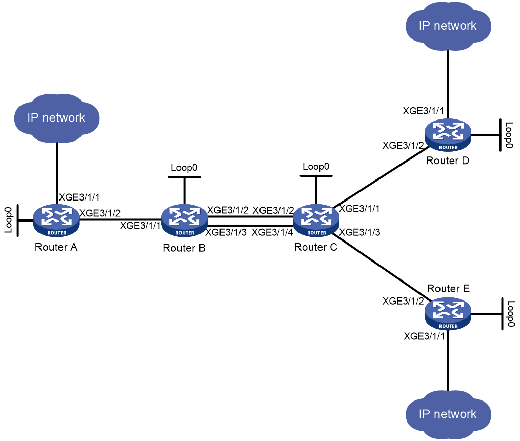
Table 1 Interface and IP address assignment
|
Device |
Interface |
IP address |
Device |
Interface |
IP address |
|
Router A |
Loop0 |
1.1.1.9/32 |
Router B |
Loop0 |
2.2.2.9/32 |
|
|
XGE3/1/1 |
100.1.1.1/24 |
|
XGE3/1/1 |
10.1.1.2/24 |
|
|
XGE3/1/2 |
10.1.1.1/24 |
|
XGE3/1/2 |
20.1.1.1/24 |
|
|
|
|
|
XGE3/1/3 |
60.1.1.1/24 |
|
Router C |
Loop0 |
3.3.3.9/32 |
Router D |
Loop0 |
4.4.4.9/32 |
|
|
XGE3/1/1 |
30.1.1.1/24 |
|
XGE3/1/1 |
100.1.2.1/24 |
|
|
XGE3/1/2 |
20.1.1.2/24 |
|
XGE3/1/2 |
30.1.1.2/24 |
|
|
XGE3/1/3 |
50.1.1.1/24 |
|
|
|
|
|
XGE3/1/4 |
60.1.1.2/24 |
|
|
|
|
Router E |
Loop0 |
5.5.5.9/32 |
|
|
|
|
|
XGE3/1/1 |
200.1.2.1/24 |
|
|
|
|
|
XGE3/1/2 |
50.1.1.2/24 |
|
|
|
Procedure
1. Configure IP addresses and masks for interfaces. (Details not shown.)
2. Configure IS-IS to advertise interface addresses, including the loopback interface addresses. (Details not shown.)
3. Execute the display ip routing-table command on each router to verify that the routers have learned the routes to one another, including the routes to the loopback interfaces. (Details not shown.)
4. Configure Router A:
# Configure the LSR ID, and enable MPLS and MPLS TE.
<RouterA> system-view
[RouterA] mpls lsr-id 1.1.1.9
[RouterA] mpls te
[RouterA-te] quit
[RouterA] interface ten-gigabitethernet 3/1/2
[RouterA-Ten-GigabitEthernet3/1/2] mpls enable
[RouterA-Ten-GigabitEthernet3/1/2] quit
# Create adjacency segment adjacency-1, and bind incoming label 16 to next hop address 10.1.1.2.
[RouterA] static-sr-mpls adjacency adjacency-1 in-label 16 nexthop 10.1.1.2
# Configure a static SRLSP (static-sr-lsp-1) to Router D, setting the label stack to [16, 21, 30].
[RouterA] static-sr-mpls lsp static-sr-lsp-1 out-label 16 21 30
# Configure a static SRLSP (static-sr-lsp-2) to Router E, setting the label stack to [16, 16000, 31].
[RouterA] static-sr-mpls lsp static-sr-lsp-2 out-label 16 16000 31
# Establish static MPLS TE tunnel 1 to Router D. Specify the LSR ID of Router D as the tunnel destination address and bind static SRLSP static-sr-lsp-1 to MPLS TE tunnel interface 1.
[RouterA] interface tunnel 1 mode mpls-te
[RouterA-Tunnel1] ip address 6.1.1.1 255.255.255.0
[RouterA-Tunnel1] destination 4.4.4.9
[RouterA-Tunnel1] mpls te signaling static
[RouterA-Tunnel1] mpls te static-sr-mpls static-sr-lsp-1
[RouterA-Tunnel1] quit
# Establish static MPLS TE tunnel 2 to Router E. Specify the LSR ID of Router E as the tunnel destination address and bind static SRLSP static-sr-lsp-2 to MPLS TE tunnel interface 2.
[RouterA] interface tunnel 2 mode mpls-te
[RouterA-Tunnel2] ip address 7.1.1.1 255.255.255.0
[RouterA-Tunnel2] destination 5.5.5.9
[RouterA-Tunnel2] mpls te signaling static
[RouterA-Tunnel2] mpls te static-sr-mpls static-sr-lsp-2
[RouterA-Tunnel2] quit
# Configure two static routes to direct traffic destined for 100.1.2.0/24 and 200.1.2.0/24 to MPLS TE tunnel 1 and tunnel 2, respectively.
[RouterA] ip route-static 100.1.2.0 24 tunnel 1 preference 1
[RouterA] ip route-static 200.1.2.0 24 tunnel 2 preference 1
5. Configure Router B:
# Configure the LSR ID, and enable MPLS and MPLS TE.
<RouterB> system-view
[RouterB] mpls lsr-id 2.2.2.9
[RouterB] mpls te
[RouterB-te] quit
[RouterB] interface ten-gigabitethernet 3/1/1
[RouterB-Ten-GigabitEthernet3/1/1] mpls enable
[RouterB-Ten-GigabitEthernet3/1/1] quit
[RouterB] interface ten-gigabitethernet 3/1/2
[RouterB-Ten-GigabitEthernet3/1/2] mpls enable
[RouterB-Ten-GigabitEthernet3/1/2] quit
[RouterB] interface ten-gigabitethernet 3/1/3
[RouterB-Ten-GigabitEthernet3/1/3] mpls enable
[RouterB-Ten-GigabitEthernet3/1/3] quit
# Create adjacency segment adjacency-2, and bind incoming label 21 to next hop address 20.1.1.2.
[RouterB] static-sr-mpls adjacency adjacency-2 in-label 21 nexthop 20.1.1.2
# Create prefix segments prefix-1 to destination IP address 5.5.5.9. Bind incoming label 16000 to next hop addresses 20.1.1.2 and 60.1.1.2, and specify outgoing label 16001. Load balancing will occur between Router B and Router C.
[RouterB] static-sr-mpls prefix prefix-1 destination 5.5.5.9 32 in-label 16000 nexthop 20.1.1.2 out-label 16001
[RouterB] static-sr-mpls prefix prefix-1 destination 5.5.5.9 32 in-label 16000 nexthop 60.1.1.2 out-label 16001
6. Configure Router C:
# Configure the LSR ID, and enable MPLS and MPLS TE.
<RouterC> system-view
[RouterC] mpls lsr-id 3.3.3.9
[RouterC] mpls te
[RouterC-te] quit
[RouterC] interface ten-gigabitethernet 3/1/1
[RouterC-Ten-GigabitEthernet3/1/1] mpls enable
[RouterC-Ten-GigabitEthernet3/1/1] quit
[RouterC] interface ten-gigabitethernet 3/1/2
[RouterC-Ten-GigabitEthernet3/1/2] mpls enable
[RouterC-Ten-GigabitEthernet3/1/2] quit
[RouterC] interface ten-gigabitethernet 3/1/3
[RouterC-Ten-GigabitEthernet3/1/3] mpls enable
[RouterC-Ten-GigabitEthernet3/1/3] quit
[RouterC] interface ten-gigabitethernet 3/1/4
[RouterC-Ten-GigabitEthernet3/1/4] mpls enable
[RouterC-Ten-GigabitEthernet3/1/4] quit
# Create adjacency segment adjacency-1, and bind incoming label 30 to next hop address 30.1.1.2. Create adjacency segment adjacency-2, and bind incoming label 31 to next hop address 50.1.1.2.
[RouterC] static-sr-mpls adjacency adjacency-1 in-label 30 nexthop 30.1.1.2
[RouterC] static-sr-mpls adjacency adjacency-2 in-label 31 nexthop 50.1.1.2
# Create prefix segment prefix-1 to destination IP address 5.5.5.9, and specify incoming label 16001.
[RouterC] static-sr-mpls prefix prefix-1 destination 5.5.5.9 32 in-label 16001
7. Configure Router D:
# Configure the LSR ID, and enable MPLS and MPLS TE.
<RouterD> system-view
[RouterD] mpls lsr-id 4.4.4.9
[RouterD] mpls te
[RouterD-te] quit
[RouterD] interface ten-gigabitethernet 3/1/2
[RouterD-Ten-GigabitEthernet3/1/2] mpls enable
[RouterD-Ten-GigabitEthernet3/1/2] quit
8. Configure Router E:
# Configure the LSR ID, and enable MPLS and MPLS TE.
<RouterE> system-view
[RouterE] mpls lsr-id 5.5.5.9
[RouterE] mpls te
[RouterE-te] quit
[RouterE] interface ten-gigabitethernet 3/1/2
[RouterE-Ten-GigabitEthernet3/1/2] mpls enable
[RouterE-Ten-GigabitEthernet3/1/2] quit
Verifying the configuration
# Display the MPLS TE tunnel information on Router A.
[RouterA] display mpls te tunnel-interface
Tunnel Name : Tunnel 1
Tunnel State : Up (Main CRLSP up)
Tunnel Attributes :
LSP ID : 1 Tunnel ID : 0
Admin State : Normal
Ingress LSR ID : 1.1.1.9 Egress LSR ID : 4.4.4.9
Signaling : Static Static CRLSP Name : -
Static SRLSP Name : static-sr-lsp-1/-
Resv Style : -
Tunnel mode : -
Reverse-LSP name : -
Reverse-LSP LSR ID : - Reverse-LSP Tunnel ID: -
Class Type : - Tunnel Bandwidth : -
Reserved Bandwidth : -
Setup Priority : 0 Holding Priority : 0
Affinity Attr/Mask : -/-
Explicit Path : -
Backup Explicit Path : -
Metric Type : TE
Record Route : - Record Label : -
FRR Flag : - Backup Bandwidth Flag: -
Backup Bandwidth Flag: - Backup Bandwidth Type: -
Backup Bandwidth : -
Bypass Tunnel : - Auto Created : -
Route Pinning : -
Retry Limit : 3 Retry Interval : 2 sec
Reoptimization : - Reoptimization Freq : -
Backup Type : - Backup LSP ID : -
Auto Bandwidth : - Auto Bandwidth Freq : -
Min Bandwidth : - Max Bandwidth : -
Collected Bandwidth : -
Traffic Policy : Disable Reserved for binding : No
Path SetupType : -/-
Binding SID : - Binding SID State : -
Last Down Reason : Admin Down
Down Time : 2017-12-05 11:23:35:535
Tunnel Name : Tunnel 2
Tunnel State : Up (Main CRLSP up)
Tunnel Attributes :
LSP ID : 1 Tunnel ID : 1
Admin State : Normal
Ingress LSR ID : 1.1.1.9 Egress LSR ID : 5.5.5.9
Signaling : Static Static CRLSP Name : -
Static SRLSP Name : static-sr-lsp-2/-
Resv Style : -
Tunnel mode : -
Reverse-LSP name : -
Reverse-LSP LSR ID : - Reverse-LSP Tunnel ID: -
Class Type : - Tunnel Bandwidth : -
Reserved Bandwidth : -
Setup Priority : 0 Holding Priority : 0
Affinity Attr/Mask : -/-
Explicit Path : -
Backup Explicit Path : -
Metric Type : TE
Record Route : - Record Label : -
FRR Flag : - Bandwidth Protection : -
Backup Bandwidth Flag: - Backup Bandwidth Type: -
Backup Bandwidth : -
Bypass Tunnel : - Auto Created : -
Route Pinning : -
Retry Limit : 3 Retry Interval : 2 sec
Reoptimization : - Reoptimization Freq : -
Backup Type : - Backup LSP ID : -
Auto Bandwidth : - Auto Bandwidth Freq : -
Min Bandwidth : - Max Bandwidth : -
Collected Bandwidth : -
Traffic Policy : Disable Reserved for binding : No
Path SetupType : -/-
Binding SID : - Binding SID State : -
Last Down Reason : Admin Down
Down Time : 2017-12-05 11:23:35:535
# Display static SRLSP establishment on each router by using the display mpls lsp or display mpls static-sr-mpls command.
[RouterA] display mpls lsp
FEC Proto In/Out Label Out Inter/NHLFE/LSINDEX
1.1.1.9/0/46565 StaticCR -/21 XGE3/1/2
30
1.1.1.9/1/46565 StaticCR -/16000 XGE3/1/2
31
- StaticCR 16/- XGE3/1/2
10.1.1.2 Local -/- XGE3/1/2
Tunnel0 Local -/- NHLFE1
Tunnel1 Local -/- NHLFE2
[RouterB] display mpls lsp
FEC Proto In/Out Label Out Inter/NHLFE/LSINDEX
5.5.5.9/32 StaticCR 16000/16001 XGE3/1/2
5.5.5.9/32 StaticCR 16000/16001 XGE3/1/3
- StaticCR 21/- XGE3/1/2
20.1.1.2 Local -/- XGE3/1/2
60.1.1.2 Local -/- XGE3/1/3
[RouterC] display mpls lsp
FEC Proto In/Out Label Out Inter/NHLFE/LSINDEX
5.5.5.9/32 StaticCR 16001/- -
- StaticCR 30/- XGE3/1/1
- StaticCR 31/- XGE3/1/3
30.1.1.2 Local -/- XGE3/1/3
50.1.1.2 Local -/- XGE3/1/3
Example: Configuring SR-MPLS based on ISIS-advertised SIDs
Network configuration
As shown in Figure 22, Router A, Router B, Router C, and Router D are running IS-IS.
Configure dynamic SID allocation on loopback interfaces of the routers. Then, establish an SRLSP from Router A to Router D based on the allocated SIDs and configure an MPLS TE tunnel over the SRLSP to transmit data.

Table 2 Interface and IP address assignment
|
Device |
Interface |
IP address |
Device |
Interface |
IP address |
|
Router A |
Loop1 |
1.1.1.1/32 |
Router B |
Loop1 |
2.2.2.2/32 |
|
|
10.0.0.1/24 |
|
XGE3/1/1 |
10.0.0.2/24 |
|
|
|
|
|
|
XGE3/1/2 |
11.0.0.1/24 |
|
Router C |
Loop1 |
3.3.3.3/32 |
Router D |
Loop1 |
4.4.4.4/32 |
|
|
XGE3/1/1 |
11.0.0.2/24 |
|
XGE3/1/1 |
12.0.0.2/24 |
|
|
XGE3/1/2 |
12.0.0.1/24 |
|
XGE3/1/2 |
100.1.2.1/24 |
Procedure
1. Configure IP addresses and masks for interfaces. (Details not shown.)
2. Configure Router A:
# Configure IS-IS and set the IS-IS cost style to wide.
<RouterA> system-view
[RouterA] isis 1
[RouterA-isis-1] network-entity 00.0000.0000.0001.00
[RouterA-isis-1] cost-style wide
[RouterA-isis-1] quit
[RouterA] interface ten-gigabitethernet 3/1/1
[RouterA-Ten-GigabitEthernet3/1/1] isis enable 1
[RouterA-Ten-GigabitEthernet3/1/1] quit
[RouterA] interface loopback 1
[RouterA-LoopBack1] isis enable 1
[RouterA-LoopBack1] quit
# Configure the LSR ID, and enable MPLS and MPLS TE.
[RouterA] mpls lsr-id 1.1.1.1
[RouterA] mpls te
[RouterA-te] quit
[RouterA] interface ten-gigabitethernet 3/1/1
[RouterA-Ten-GigabitEthernet3/1/1] mpls enable
[RouterA-Ten-GigabitEthernet3/1/1] quit
# Enable SR-MPLS.
[RouterA] isis 1
[RouterA-isis-1] address-family ipv4
[RouterA-isis-1-ipv4] segment-routing mpls
[RouterA-isis-1-ipv4] quit
[RouterA-isis-1] quit
# Configure the IS-IS prefix SID.
[RouterA] interface loopback 1
[RouterA-LoopBack1] isis prefix-sid index 10
[RouterA-LoopBack1] quit
# Configure a static SRLSP (static-sr-lsp-1) to Router D, setting the outgoing label to the prefix label that Router A allocated to Router D (16040).
[RouterA] static-sr-mpls lsp static-sr-lsp-1 out-label 16040
# Establish static MPLS TE tunnel 1 to Router D. Specify the LSR ID of Router D as the tunnel destination address and bind static SRLSP static-sr-lsp-1 to MPLS TE tunnel interface 1.
[RouterA] interface tunnel 1 mode mpls-te
[RouterA-Tunnel1] ip address 6.1.1.1 255.255.255.0
[RouterA-Tunnel1] destination 4.4.4.4
[RouterA-Tunnel1] mpls te signaling static
[RouterA-Tunnel1] mpls te static-sr-mpls static-sr-lsp-1
[RouterA-Tunnel1] quit
# Configure a static route to direct traffic destined for 100.1.2.0/24 to MPLS TE tunnel 1.
[RouterA] ip route-static 100.1.2.0 24 tunnel 1 preference 1
3. Configure Router B:
# Configure IS-IS and set the IS-IS cost style to wide.
<RouterB> system-view
[RouterB] isis 1
[RouterB-isis-1] network-entity 00.0000.0000.0002.00
[RouterB-isis-1] cost-style wide
[RouterB-isis-1] quit
[RouterB] interface ten-gigabitethernet 3/1/1
[RouterB-Ten-GigabitEthernet3/1/1] isis enable 1
[RouterB-Ten-GigabitEthernet3/1/1] quit
[RouterB] interface ten-gigabitethernet 3/1/2
[RouterB-Ten-GigabitEthernet3/1/2] isis enable 1
[RouterB-Ten-GigabitEthernet3/1/2] quit
[RouterB] interface loopback 1
[RouterB-LoopBack1] isis enable 1
[RouterB-LoopBack1] quit
# Configure the LSR ID, and enable MPLS and MPLS TE.
[RouterB] mpls lsr-id 2.2.2.2
[RouterB] mpls te
[RouterB-te] quit
[RouterB] interface ten-gigabitethernet 3/1/1
[RouterB-Ten-GigabitEthernet3/1/1] mpls enable
[RouterB-Ten-GigabitEthernet3/1/1] quit
[RouterB] interface ten-gigabitethernet 3/1/2
[RouterB-Ten-GigabitEthernet3/1/2] mpls enable
[RouterB-Ten-GigabitEthernet3/1/2] quit
# Enable SR-MPLS.
[RouterB] isis 1
[RouterB-isis-1] address-family ipv4
[RouterB-isis-1-ipv4] segment-routing mpls
[RouterB-isis-1-ipv4] quit
[RouterB-isis-1] quit
# Configure the IS-IS prefix SID.
[RouterB] interface loopback 1
[RouterB-LoopBack1] isis prefix-sid index 20
4. Configure Router C:
# Configure IS-IS and set the IS-IS cost style to wide.
<RouterC> system-view
[RouterC] isis 1
[RouterC-isis-1] network-entity 00.0000.0000.0003.00
[RouterC-isis-1] cost-style wide
[RouterC-isis-1] quit
[RouterC] interface ten-gigabitethernet 3/1/1
[RouterC-Ten-GigabitEthernet3/1/1] isis enable 1
[RouterC-Ten-GigabitEthernet3/1/1] quit
[RouterC] interface ten-gigabitethernet 3/1/2
[RouterC-Ten-GigabitEthernet3/1/2] isis enable 1
[RouterC-Ten-GigabitEthernet3/1/2] quit
[RouterC] interface loopback 1
[RouterC-LoopBack1] isis enable 1
[RouterC-LoopBack1] quit
# Configure the LSR ID, and enable MPLS and MPLS TE.
[RouterC] mpls lsr-id 3.3.3.3
[RouterC] mpls te
[RouterC-te] quit
[RouterC] interface ten-gigabitethernet 3/1/1
[RouterC-Ten-GigabitEthernet3/1/1] mpls enable
[RouterC-Ten-GigabitEthernet3/1/1] quit
[RouterC] interface ten-gigabitethernet 3/1/2
[RouterC-Ten-GigabitEthernet3/1/2] mpls enable
[RouterC-Ten-GigabitEthernet3/1/2] quit
# Enable SR-MPLS.
[RouterC] isis 1
[RouterC-isis-1] address-family ipv4
[RouterC-isis-1-ipv4] segment-routing mpls
[RouterC-isis-1-ipv4] quit
[RouterC-isis-1] quit
# Configure the IS-IS prefix SID.
[RouterC] interface loopback 1
[RouterC-LoopBack1] isis prefix-sid index 30
5. Configure Router D:
# Configure IS-IS and set the IS-IS cost style to wide.
<RouterD> system-view
[RouterD] isis 1
[RouterD-isis-1] network-entity 00.0000.0000.0004.00
[RouterD-isis-1] cost-style wide
[RouterD-isis-1] quit
[RouterD] interface ten-gigabitethernet 3/1/1
[RouterD-Ten-GigabitEthernet3/1/1] isis enable 1
[RouterD-Ten-GigabitEthernet3/1/1] quit
[RouterD] interface ten-gigabitethernet 3/1/2
[RouterD-Ten-GigabitEthernet3/1/2] isis enable 1
[RouterD-Ten-GigabitEthernet3/1/2] quit
[RouterD] interface loopback 1
[RouterD-LoopBack1] isis enable 1
[RouterD-LoopBack1] quit
# Configure the LSR ID, and enable MPLS and MPLS TE.
[RouterD] mpls lsr-id 4.4.4.4
[RouterD] mpls te
[RouterD-te] quit
[RouterD] interface ten-gigabitethernet 3/1/1
[RouterD-Ten-GigabitEthernet3/1/1] mpls enable
[RouterD-Ten-GigabitEthernet3/1/1] quit
# Enable SR-MPLS.
[RouterD] isis 1
[RouterD-isis-1] address-family ipv4
[RouterD-isis-1-ipv4] segment-routing mpls
[RouterD-isis-1-ipv4] quit
[RouterD-isis-1] quit
# Configure the IS-IS prefix SID.
[RouterD] interface loopback 1
[RouterD-LoopBack1] isis prefix-sid index 40
Verifying the configuration
# Display detailed IS-IS interface information on Router A to view SID information for the loopback interface.
[RouterA] display isis interface verbose
Interface information for IS-IS(1)
----------------------------------
Interface: LoopBack1
Index IPv4 state IPv6 state Circuit ID MTU Type DIS
00002 Up Down 1 1536 L1/L2 --
SNPA address : 0000-0000-0000
IP address : 1.1.1.1
Secondary IP address(es) :
IPv6 link-local address :
Extended circuit ID : 2
CSNP timer value : L1 10 L2 10
Hello timer value : 10
Hello multiplier value : 3
LSP timer value : L12 33
LSP transmit-throttle count : L12 5
Cost : L1 0 L2 0
IPv6 cost : L1 0 L2 0
Priority : L1 64 L2 64
Retransmit timer value : L12 5
MPLS TE status : L1 Disabled L2 Disabled
IPv4 BFD : Disabled
IPv6 BFD : Disabled
IPv4 FRR LFA backup : Enabled
IPv6 FRR LFA backup : Enabled
IPv4 prefix suppression : Disabled
IPv6 prefix suppression : Disabled
IPv4 tag : 0
IPv6 tag : 0
Prefix-SID type : Index
Value : 10
Prefix-SID validity : Valid
# Display detailed IS-IS routing information on Router A to view information about routes bound with labels.
[RouterA] display isis route verbose
Route information for IS-IS(1)
------------------------------
Level-1 IPv4 Forwarding Table
-----------------------------
IPv4 Dest : 10.0.0.0/24 Int. Cost : 10 Ext. Cost : NULL
Admin Tag : - Src Count : 2 Flag : D/L/-
InLabel : 4294967295 InLabel Flag: -/-/-/-/-/-
NextHop : Interface : ExitIndex :
Direct XGE3/1/1 0x00000102
Nib ID : 0x0 OutLabel : 4294967295 OutLabelFlag: -
IPv4 Dest : 11.0.0.0/24 Int. Cost : 20 Ext. Cost : NULL
Admin Tag : - Src Count : 2 Flag : R/-/-
InLabel : 4294967295 InLabel Flag: -/-/-/-/-/-
NextHop : Interface : ExitIndex :
10.0.0.2 XGE3/1/1 0x00000102
Nib ID : 0x14000004 OutLabel : 4294967295 OutLabelFlag: -
IPv4 Dest : 12.0.0.0/24 Int. Cost : 30 Ext. Cost : NULL
Admin Tag : - Src Count : 2 Flag : R/-/-
InLabel : 4294967295 InLabel Flag: -/-/-/-/-/-
NextHop : Interface : ExitIndex :
10.0.0.2 XGE3/1/1 0x00000102
Nib ID : 0x14000004 OutLabel : 4294967295 OutLabelFlag: -
IPv4 Dest : 1.1.1.1/32 Int. Cost : 0 Ext. Cost : NULL
Admin Tag : - Src Count : 1 Flag : D/L/-
InLabel : 16010 InLabel Flag: -/N/-/-/-/-
NextHop : Interface : ExitIndex :
Direct Loop1 0x00000584
Nib ID : 0x0 OutLabel : 4294967295 OutLabelFlag: -
IPv4 Dest : 2.2.2.2/32 Int. Cost : 10 Ext. Cost : NULL
Admin Tag : - Src Count : 1 Flag : R/-/-
InLabel : 16020 InLabel Flag: -/N/-/-/-/-
NextHop : Interface : ExitIndex :
10.0.0.2 XGE3/1/1 0x00000102
Nib ID : 0x14000003 OutLabel : 16020 OutLabelFlag: I
IPv4 Dest : 3.3.3.3/32 Int. Cost : 20 Ext. Cost : NULL
Admin Tag : - Src Count : 1 Flag : R/-/-
InLabel : 16030 InLabel Flag: -/N/-/-/-/-
NextHop : Interface : ExitIndex :
10.0.0.2 XGE3/1/1 0x00000102
Nib ID : 0x14000002 OutLabel : 16030 OutLabelFlag: -
IPv4 Dest : 4.4.4.4/32 Int. Cost : 20 Ext. Cost : NULL
Admin Tag : - Src Count : 1 Flag : R/-/-
InLabel : 16040 InLabel Flag: -/N/-/-/-/-
NextHop : Interface : ExitIndex :
10.0.0.2 XGE3/1/1 0x00000102
Nib ID : 0x14000002 OutLabel : 16040 OutLabelFlag: -
Flags: D-Direct, R-Added to Rib, L-Advertised in LSPs, U-Up/Down Bit Set
InLabel flags: R-Readvertisement, N-Node SID, P-no PHP
E-Explicit null, V-Value, L-Local
OutLabelFlags: E-Explicit null, I-Implicit null, N-Normal
# Display MPLS LSP information on Router A.
[RouterA] display mpls lsp
FEC Proto In/Out Label Out Inter/NHLFE/LSINDEX
10.0.0.2 Local -/- XGE3/1/1
1.1.1.1/32 ISIS 16010/- -
2.2.2.2/32 ISIS 16020/3 XGE3/1/1
2.2.2.2/32 ISIS -/3 XGE3/1/1
3.3.3.3/32 ISIS 16030/16030 XGE3/1/1
3.3.3.3/32 ISIS -/16030 XGE3/1/1
4.4.4.4/32 ISIS 16040/16040 XGE3/1/1
4.4.4.4/32 ISIS -/16040 XGE3/1/1
Example: Configuring SR-MPLS based on OSPF-advertised SIDs
Network configuration
As shown in Figure 23, Router A, Router B, Router C, and Router D are running OSPF.
Configure dynamic SID allocation on loopback interfaces of the routers. Then, establish an SRLSP from Router A to Router D based on the allocated SIDs and configure an MPLS TE tunnel over the SRLSP to transmit data.

Table 3 Interface and IP address assignment
|
Device |
Interface |
IP address |
Device |
Interface |
IP address |
|
Router A |
Loop1 |
1.1.1.1/32 |
Router B |
Loop1 |
2.2.2.2/32 |
|
|
XGE3/1/1 |
10.0.0.1/24 |
|
XGE3/1/1 |
10.0.0.2/24 |
|
|
|
|
|
XGE3/1/2 |
11.0.0.1/24 |
|
Router C |
Loop1 |
3.3.3.3/32 |
Router D |
Loop1 |
4.4.4.4/32 |
|
|
XGE3/1/1 |
11.0.0.2/24 |
|
XGE3/1/1 |
12.0.0.2/24 |
|
|
XGE3/1/2 |
12.0.0.1/24 |
|
XGE3/1/2 |
100.1.2.1/24 |
Procedure
1. Configure IP addresses and masks for interfaces. (Details not shown.)
2. Configure Router A:
# Configure OSPF to achieve network level connectivity.
<RouterA> system-view
[RouterA] ospf 1 router-id 1.1.1.1
[RouterA-ospf-1] quit
[RouterA] interface ten-gigabitethernet 3/1/1
[RouterA-Ten-GigabitEthernet3/1/1] ospf 1 area 0
[RouterA-Ten-GigabitEthernet3/1/1] quit
[RouterA] interface loopback 1
[RouterA-LoopBack1] ospf 1 area 0
[RouterA-LoopBack1] quit
# Configure the LSR ID, and enable MPLS and MPLS TE.
[RouterA] mpls lsr-id 1.1.1.1
[RouterA] mpls te
[RouterA-te] quit
[RouterA] interface ten-gigabitethernet 3/1/1
[RouterA-Ten-GigabitEthernet3/1/1] mpls enable
[RouterA-Ten-GigabitEthernet3/1/1] quit
# Enable SR-MPLS.
[RouterA] ospf 1
[RouterA-ospf-1] segment-routing mpls
[RouterA-ospf-1] quit
# Configure the OSPF prefix SID by specifying a relative value.
[RouterA] interface loopback 1
[RouterA-LoopBack1] ospf 1 prefix-sid index 10
[RouterA-LoopBack1] quit
# Configure a static SRLSP (static-sr-lsp-1) to Router D, setting the outgoing label to the prefix label that Router A allocated to Router D (16040).
[RouterA] static-sr-mpls lsp static-sr-lsp-1 out-label 16040
# Establish static MPLS TE tunnel 1 to Router D. Specify the LSR ID of Router D as the tunnel destination address and bind static SRLSP static-sr-lsp-1 to MPLS TE tunnel interface 1.
[RouterA] interface tunnel 1 mode mpls-te
[RouterA-Tunnel1] ip address 6.1.1.1 255.255.255.0
[RouterA-Tunnel1] destination 4.4.4.4
[RouterA-Tunnel1] mpls te signaling static
[RouterA-Tunnel1] mpls te static-sr-mpls static-sr-lsp-1
[RouterA-Tunnel1] quit
# Configure a static route to direct traffic destined for 100.1.2.0/24 to MPLS TE tunnel 1.
[RouterA] ip route-static 100.1.2.0 24 tunnel 1 preference 1
3. Configure Router B:
# Configure OSPF to achieve network level connectivity.
<RouterB> system-view
[RouterB] ospf 1 router-id 2.2.2.2
[RouterB-ospf-1] quit
[RouterB] interface ten-gigabitethernet 3/1/1
[RouterB-Ten-GigabitEthernet3/1/1] ospf 1 area 0
[RouterB-Ten-GigabitEthernet3/1/1] quit
[RouterB] interface ten-gigabitethernet 3/1/2
[RouterB-Ten-GigabitEthernet3/1/2] ospf 1 area 0
[RouterB-Ten-GigabitEthernet3/1/2] quit
[RouterB] interface loopback 1
[RouterB-LoopBack1] ospf 1 area 0
[RouterB-LoopBack1] quit
# Configure the LSR ID, and enable MPLS and MPLS TE.
[RouterB] mpls lsr-id 2.2.2.2
[RouterB] mpls te
[RouterB-te] quit
[RouterB] interface ten-gigabitethernet 3/1/1
[RouterB-Ten-GigabitEthernet3/1/1] mpls enable
[RouterB-Ten-GigabitEthernet3/1/1] quit
[RouterB] interface ten-gigabitethernet 3/1/2
[RouterB-Ten-GigabitEthernet3/1/2] mpls enable
[RouterB-Ten-GigabitEthernet3/1/2] quit
# Enable SR-MPLS.
[RouterB] ospf 1
[RouterB-ospf-1] segment-routing mpls
[RouterB-ospf-1] quit
# Configure the OSPF prefix SID by specifying a relative value.
[RouterB] interface loopback 1
[RouterB-LoopBack1] ospf 1 prefix-sid index 20
4. Configure Router C:
# Configure OSPF to achieve network level connectivity.
<RouterC> system-view
[RouterC] ospf 1 router-id 3.3.3.3
[RouterC-ospf-1] quit
[RouterC] interface ten-gigabitethernet 3/1/1
[RouterC-Ten-GigabitEthernet3/1/1] ospf 1 area 0
[RouterC-Ten-GigabitEthernet3/1/1] quit
[RouterC] interface ten-gigabitethernet 3/1/2
[RouterC-Ten-GigabitEthernet3/1/2] ospf 1 area 0
[RouterC-Ten-GigabitEthernet3/1/2] quit
[RouterC] interface loopback 1
[RouterC-LoopBack1] ospf 1 area 0
[RouterC-LoopBack1] quit
# Configure the LSR ID, and enable MPLS and MPLS TE.
[RouterC] mpls lsr-id 3.3.3.3
[RouterC] mpls te
[RouterC-te] quit
[RouterC] interface ten-gigabitethernet 3/1/1
[RouterC-Ten-GigabitEthernet3/1/1] mpls enable
[RouterC-Ten-GigabitEthernet3/1/1] quit
[RouterC] interface ten-gigabitethernet 3/1/2
[RouterC-Ten-GigabitEthernet3/1/2] mpls enable
[RouterC-Ten-GigabitEthernet3/1/2] quit
# Enable SR-MPLS.
[RouterC] ospf 1
[RouterC-ospf-1] segment-routing mpls
[RouterC-ospf-1] quit
# Configure the OSPF prefix SID by specifying a relative value.
[RouterC] interface loopback 1
[RouterC-LoopBack1] ospf 1 prefix-sid index 30
5. Configure Router D:
# Configure OSPF to achieve network level connectivity.
<RouterD> system-view
[RouterD] ospf 1 router-id 4.4.4.4
[RouterD-ospf-1] quit
[RouterD] interface ten-gigabitethernet 3/1/1
[RouterD-Ten-GigabitEthernet3/1/1] ospf 1 area 0
[RouterD-Ten-GigabitEthernet3/1/1] quit
[RouterD] interface ten-gigabitethernet 3/1/2
[RouterD-Ten-GigabitEthernet3/1/2] ospf 1 area 0
[RouterD-Ten-GigabitEthernet3/1/2] quit
[RouterD] interface loopback 1
[RouterD-LoopBack1] ospf 1 area 0
[RouterD-LoopBack1] quit
# Configure the LSR ID, and enable MPLS and MPLS TE.
[RouterD] mpls lsr-id 4.4.4.4
[RouterD] mpls te
[RouterD-te] quit
[RouterD] interface ten-gigabitethernet 3/1/1
[RouterD-Ten-GigabitEthernet3/1/1] mpls enable
[RouterD-Ten-GigabitEthernet3/1/1] quit
# Enable SR-MPLS.
[RouterD] ospf 1
[RouterD-ospf-1] segment-routing mpls
[RouterD-ospf-1] quit
# Configure the OSPF prefix SID by specifying a relative value.
[RouterD] interface loopback 1
[RouterD-LoopBack1] ospf 1 prefix-sid index 40
Verifying the configuration
# Display detailed OSPF routing information on Router A to view information about routes bound with labels.
[RouterA] display ospf routing verbose
OSPF Process 1 with Router ID 1.1.1.1
Routing Table
Topology base (MTID 0)
Routing for network
Destination: 11.0.0.0/24
Priority: Low Type: Transit
AdvRouter: 3.3.3.3 Area: 0.0.0.0
SubProtoID: 0x1 Preference: 10
NextHop: 10.0.0.2 BkNextHop: N/A
IfType: Broadcast BkIfType: N/A
Interface: XGE3/1/1 BkInterface: N/A
NibID: 0x13000005 Status: Normal
Cost: 2
InLabel: 4294967295
OutLabel: 4294967295 OutLabel flag: N
Destination: 10.0.0.0/24
Priority: Low Type: Transit
AdvRouter: 1.1.1.1 Area: 0.0.0.0
SubProtoID: 0x1 Preference: 10
NextHop: 0.0.0.0 BkNextHop: N/A
IfType: Broadcast BkIfType: N/A
Interface: XGE3/1/1 BkInterface: N/A
NibID: 0x13000001 Status: Direct
Cost: 1
InLabel: 4294967295
OutLabel: 4294967295 OutLabel flag: N
Destination: 4.4.4.4/32
Priority: Medium Type: Stub
AdvRouter: 4.4.4.4 Area: 0.0.0.0
SubProtoID: 0x1 Preference: 10
NextHop: 10.0.0.2 BkNextHop: N/A
IfType: Broadcast BkIfType: N/A
Interface: XGE3/1/1 BkInterface: N/A
NibID: 0x13000005 Status: Normal
Cost: 2
InLabel: 16040
OutLabel: 16040 OutLabel flag: N
Destination: 3.3.3.3/32
Priority: Medium Type: Stub
AdvRouter: 3.3.3.3 Area: 0.0.0.0
SubProtoID: 0x1 Preference: 10
NextHop: 10.0.0.2 BkNextHop: N/A
IfType: Broadcast BkIfType: N/A
Interface: XGE3/1/1 BkInterface: N/A
NibID: 0x13000005 Status: Normal
Cost: 2
InLabel: 16030
OutLabel: 16030 OutLabel flag: N
Destination: 2.2.2.2/32
Priority: Medium Type: Stub
AdvRouter: 2.2.2.2 Area: 0.0.0.0
SubProtoID: 0x1 Preference: 10
NextHop: 10.0.0.2 BkNextHop: N/A
IfType: Broadcast BkIfType: N/A
Interface: XGE3/1/1 BkInterface: N/A
NibID: 0x13000005 Status: Normal
Cost: 1
InLabel: 16020
OutLabel: 16020 OutLabel flag: N
Destination: 1.1.1.1/32
Priority: Medium Type: Stub
AdvRouter: 1.1.1.1 Area: 0.0.0.0
SubProtoID: 0x1 Preference: 10
NextHop: 0.0.0.0 BkNextHop: N/A
IfType: PTP BkIfType: N/A
Interface: Loop1 BkInterface: N/A
NibID: 0x13000002 Status: Direct
Cost: 0
InLabel: 16010
OutLabel: 4294967295 OutLabel flag: N
Total nets: 6
Intra area: 6 Inter area: 0 ASE: 0 NSSA: 0
# Display MPLS LSP information on Router A.
[RouterA] display mpls lsp
FEC Proto In/Out Label Out Inter/NHLFE/LSINDEX
10.0.0.2 Local -/- XGE3/1/1
1.1.1.1/32 OSPF 16010/- -
2.2.2.2/32 OSPF 16020/3 XGE3/1/1
2.2.2.2/32 OSPF -/3 XGE3/1/1
3.3.3.3/32 OSPF 16030/16030 XGE3/1/1
3.3.3.3/32 OSPF -/16030 XGE3/1/1
4.4.4.4/32 OSPF 16040/16040 XGE3/1/1
4.4.4.4/32 OSPF -/16040 XGE3/1/1
Example: Configuring an SR-based MPLS TE tunnel over an explicit path
Network configuration
As shown in Figure 24, Router A, Router B, Router C, and Router D are running IS-IS.
Configure dynamic SID allocation on loopback interfaces of the routers. Then, create an explicit path from Router A to Router D and configure the MPLS TE tunnel interface to use SR to establish an MPLS TE tunnel over the explicit path.

Table 4 Interface and IP address assignment
|
Device |
Interface |
IP address |
Device |
Interface |
IP address |
|
Router A |
Loop1 |
1.1.1.1/32 |
Router B |
Loop1 |
2.2.2.2/32 |
|
|
XGE3/1/1 |
10.0.0.1/24 |
|
XGE3/1/1 |
10.0.0.2/24 |
|
|
|
|
|
XGE3/1/2 |
11.0.0.1/24 |
|
Router C |
Loop1 |
3.3.3.3/32 |
Router D |
Loop1 |
4.4.4.4/32 |
|
|
XGE3/1/1 |
11.0.0.2/24 |
|
XGE3/1/1 |
12.0.0.2/24 |
|
|
XGE3/1/2 |
12.0.0.1/24 |
|
XGE3/1/2 |
100.1.2.1/24 |
Procedure
1. Configure IP addresses and masks for interfaces. (Details not shown.)
2. Configure Router A:
# Configure the MPLS LSR ID, and enable MPLS and MPLS TE.
<RouterA> system-view
[RouterA] mpls lsr-id 1.1.1.1
[RouterA] mpls te
[RouterA-te] quit
[RouterA] interface ten-gigabitethernet 3/1/1
[RouterA-Ten-GigabitEthernet3/1/1] mpls enable
[RouterA-Ten-GigabitEthernet3/1/1] quit
# Configure IS-IS to achieve network level connectivity and set the IS-IS cost style to wide.
[RouterA] isis 1
[RouterA-isis-1] network-entity 00.0000.0000.0001.00
[RouterA-isis-1] cost-style wide
[RouterA-isis-1] is-level level-1
[RouterA-isis-1] mpls te enable
[RouterA-isis-1] quit
[RouterA] interface ten-gigabitethernet 3/1/1
[RouterA-Ten-GigabitEthernet3/1/1] isis enable 1
[RouterA-Ten-GigabitEthernet3/1/1] quit
[RouterA] interface loopback 1
[RouterA-LoopBack1] isis enable 1
[RouterA-LoopBack1] quit
# Enable SR-MPLS.
[RouterA] isis 1
[RouterA-isis-1] address-family ipv4
[RouterA-isis-1-ipv4] segment-routing mpls
[RouterA-isis-1-ipv4] quit
[RouterA-isis-1] quit
# Configure the IS-IS prefix SID.
[RouterA] interface loopback 1
[RouterA-LoopBack1] isis prefix-sid index 10
[RouterA-LoopBack1] quit
# Create an explicit path to Router D and specify the nodes by their prefix labels.
[RouterA] explicit-path 1
[RouterA-explicit-path-1] nextsid label 16020 type prefix
[RouterA-explicit-path-1] nextsid label 16030 type prefix
[RouterA-explicit-path-1] nextsid label 16040 type prefix
[RouterA-explicit-path-1] quit
# Configure MPLS TE tunnel interface Tunnel 1.
[RouterA] interface tunnel 1 mode mpls-te
[RouterA-Tunnel1] ip address unnumbered interface loopBack 1
# Set the tunnel destination address to the IP address of the loopback interface on Router D.
[RouterA-Tunnel1] destination 4.4.4.4
# Configure the MPLS TE tunnel interface to use SR to establish a tunnel over the explicit path.
[RouterA-Tunnel1] mpls te signaling segment-routing
[RouterA-Tunnel1] mpls te path preference 1 explicit-path 1
[RouterA-Tunnel1] quit
3. Configure Router B:
# Configure the MPLS LSR ID, and enable MPLS and MPLS TE.
<RouterB> system-view
[RouterB] mpls lsr-id 2.2.2.2
[RouterB] mpls te
[RouterB-te] quit
[RouterB] interface ten-gigabitethernet 3/1/1
[RouterB-Ten-GigabitEthernet3/1/1] mpls enable
[RouterB-Ten-GigabitEthernet3/1/1] quit
[RouterB] interface ten-gigabitethernet 3/1/2
[RouterB-Ten-GigabitEthernet3/1/2] mpls enable
[RouterB-Ten-GigabitEthernet3/1/2] quit
# Configure IS-IS to achieve network level connectivity and set the IS-IS cost style to wide.
[RouterB] isis 1
[RouterB-isis-1] network-entity 00.0000.0000.0002.00
[RouterB-isis-1] cost-style wide
[RouterB-isis-1] is-level level-1
[RouterB-isis-1] mpls te enable
[RouterB-isis-1] quit
[RouterB] interface ten-gigabitethernet 3/1/1
[RouterB-Ten-GigabitEthernet3/1/1] isis enable 1
[RouterB-Ten-GigabitEthernet3/1/1] quit
[RouterB] interface ten-gigabitethernet 3/1/2
[RouterB-Ten-GigabitEthernet3/1/2] isis enable 1
[RouterB-Ten-GigabitEthernet3/1/2] quit
[RouterB] interface loopback 1
[RouterB-LoopBack1] isis enable 1
[RouterB-LoopBack1] quit
# Enable SR-MPLS on the routers.
[RouterB] isis 1
[RouterB-isis-1] address-family ipv4
[RouterB-isis-1-ipv4] segment-routing mpls
[RouterB-isis-1-ipv4] quit
[RouterB-isis-1] quit
# Configure the IS-IS prefix SID.
[RouterB] interface loopback 1
[RouterB-LoopBack1] isis prefix-sid index 20
[RouterB-LoopBack1] quit
4. Configure Router C:
# Configure the MPLS LSR ID, and enable MPLS and MPLS TE.
<RouterC> system-view
[RouterC] mpls lsr-id 3.3.3.3
[RouterC] mpls te
[RouterC-te] quit
[RouterC] interface ten-gigabitethernet 3/1/1
[RouterC-Ten-GigabitEthernet3/1/1] mpls enable
[RouterC-Ten-GigabitEthernet3/1/1] quit
[RouterC] interface ten-gigabitethernet 3/1/2
[RouterC-Ten-GigabitEthernet3/1/2] mpls enable
[RouterC-Ten-GigabitEthernet3/1/2] quit
# Configure IS-IS to achieve network level connectivity and set the IS-IS cost style to wide.
[RouterC] isis 1
[RouterC-isis-1] network-entity 00.0000.0000.0003.00
[RouterC-isis-1] cost-style wide
[RouterC-isis-1] is-level level-1
[RouterC-isis-1] mpls te enable
[RouterC-isis-1] quit
[RouterC] interface ten-gigabitethernet 3/1/1
[RouterC-Ten-GigabitEthernet3/1/1] isis enable 1
[RouterC-Ten-GigabitEthernet3/1/1] quit
[RouterC] interface ten-gigabitethernet 3/1/2
[RouterC-Ten-GigabitEthernet3/1/2] isis enable 1
[RouterC-Ten-GigabitEthernet3/1/2] quit
[RouterC] interface loopback 1
[RouterC-LoopBack1] isis enable 1
[RouterC-LoopBack1] quit
# Enable SR-MPLS on the routers.
[RouterC] isis 1
[RouterC-isis-1] address-family ipv4
[RouterC-isis-1-ipv4] segment-routing mpls
[RouterC-isis-1-ipv4] quit
[RouterC-isis-1] quit
# Configure the IS-IS prefix SID.
[RouterC] interface loopback 1
[RouterC-LoopBack1] isis prefix-sid index 30
[RouterC-LoopBack1] quit
5. Configure Router D:
# Configure the MPLS LSR ID, and enable MPLS and MPLS TE.
<RouterD> system-view
[RouterD] mpls lsr-id 4.4.4.4
[RouterD] mpls te
[RouterD-te] quit
[RouterD] interface ten-gigabitethernet 3/1/1
[RouterD-Ten-GigabitEthernet3/1/1] mpls enable
[RouterD-Ten-GigabitEthernet3/1/1] quit
# Configure IS-IS to achieve network level connectivity and set the IS-IS cost style to wide.
[RouterD] isis 1
[RouterD-isis-1] network-entity 00.0000.0000.0004.00
[RouterD-isis-1] cost-style wide
[RouterD-isis-1] is-level level-1
[RouterD-isis-1] mpls te enable
[RouterD-isis-1] quit
[RouterD] interface ten-gigabitethernet 3/1/1
[RouterD-Ten-GigabitEthernet3/1/1] isis enable 1
[RouterD-Ten-GigabitEthernet3/1/1] quit
[RouterD] interface ten-gigabitethernet 3/1/2
[RouterD-Ten-GigabitEthernet3/1/2] isis enable 1
[RouterD-Ten-GigabitEthernet3/1/2] quit
[RouterD] interface loopback 1
[RouterD-LoopBack1] isis enable 1
[RouterD-LoopBack1] quit
# Enable SR-MPLS on the routers.
[RouterD] isis 1
[RouterD-isis-1] address-family ipv4
[RouterD-isis-1-ipv4] segment-routing mpls
[RouterD-isis-1-ipv4] quit
[RouterD-isis-1] quit
# Configure the IS-IS prefix SID.
[RouterD] interface loopback 1
[RouterD-LoopBack1] isis prefix-sid index 40
[RouterD-LoopBack1] quit
Verifying the configuration
# Display MPLS LSP information on Router A.
[RouterA] display mpls lsp
FEC Proto In/Out Label Out Inter/NHLFE/LSINDEX
10.0.0.2 Local -/- XGE3/1/1
Tunnel1 Local -/- NHLFE6
1.1.1.1/32 ISIS 16010/- -
2.2.2.2/32 ISIS 16020/3 XGE3/1/1
2.2.2.2/32 ISIS -/3 XGE3/1/1
3.3.3.3/32 ISIS 16030/16030 XGE3/1/1
3.3.3.3/32 ISIS -/16030 XGE3/1/1
4.4.4.4/32 ISIS 16040/16040 XGE3/1/1
4.4.4.4/32 ISIS -/16040 XGE3/1/1
1.1.1.1/1/17700 SR-TE -/16030 XGE3/1/1
16040
# Display information about MPLS TE tunnel interface Tunnel 1 on Router A.
[RouterA] display mpls te tunnel-interface tunnel 1
Tunnel Name : Tunnel 1
Tunnel State : Up (Main CRLSP up.
Main Shared-resource CRLSP down.
Backup CRLSP down.)
Tunnel Attributes :
LSP ID : 17700 Tunnel ID : 1
Admin State : Normal
Ingress LSR ID : 1.1.1.1 Egress LSR ID : 4.4.4.4
Signaling : Segment-Routing Static CRLSP Name : -
Resv Style : SE
Tunnel mode : -
Reverse-LSP name : -
Reverse-LSP LSR ID : - Reverse-LSP Tunnel ID: -
Class Type : CT0 Tunnel Bandwidth : 0 kbps
Reserved Bandwidth : 0 kbps
Setup Priority : - Holding Priority : -
Affinity Attr/Mask : 0/0
Explicit Path : 1
Backup Explicit Path : -
Metric Type : TE
Record Route : Disabled Record Label : Disabled
FRR Flag : Disabled Bandwidth Protection : Disabled
Backup Bandwidth Flag: Disabled Backup Bandwidth Type: -
Backup Bandwidth : -
Bypass Tunnel : No Auto Created : No
Route Pinning : Disabled
Retry Limit : 3 Retry Interval : 2 sec
Reoptimization : Disabled Reoptimization Freq : -
Backup Type : None Backup LSP ID : -
Backup Restore Time : -
Auto Bandwidth : Disabled Auto Bandwidth Freq : -
Min Bandwidth : - Max Bandwidth : -
Collected Bandwidth : - Service-Class : -
Traffic Policy : Disable
Path Setup Type : EXPLICIT/-
Binding SID : - Binding SID State : -
Last Down Reason : Signal Error
Down Time : 2018-11-13 14:34:06:232
# Display the NHLFE entry information.
[RouterA] display mpls forwarding nhlfe
Total NHLFE entries: 3
Flags: T - Forwarded through a tunnel
N - Forwarded through the outgoing interface to the nexthop IP address
B - Backup forwarding information
A - Active forwarding information
M - P2MP forwarding information
NID Tnl-Type Flag OutLabel Forwarding Info
--------------------------------------------------------------------------------
5 LOCAL NA - XGE3/1/1 10.0.0.2
6 SRLSP NA 16030 XGE3/1/1 10.0.0.2
16040
268435457 TE TA - 6
The output shows that there are two tiers of outgoing labels to the destination. The traffic is forwarded through the explicit path.
Example: Configuring an MPLS TE tunnel over a PCE-calculated SRLSP
Network configuration
As shown in Figure 25, Router A, Router B, Router C, and Router D are running IS-IS.
Configure Router B, Router C, and Router D as PCEs. Configure Router A as a PCC and specify the PCEs for the PCC. Configure Router A to request the PCEs to calculate the path to Router D.
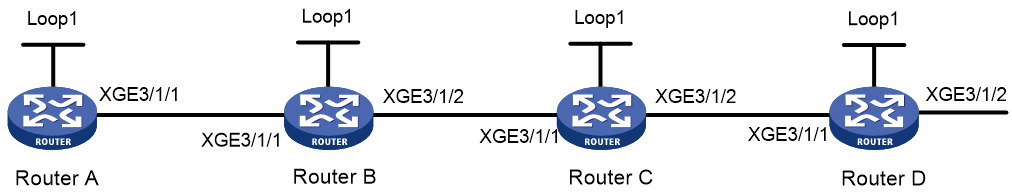
Table 5 Interface and IP address assignment
|
Device |
Interface |
IP address |
Device |
Interface |
IP address |
|
Router A |
Loop1 |
1.1.1.1/32 |
Router B |
Loop1 |
2.2.2.2/32 |
|
|
XGE3/1/1 |
10.0.0.1/24 |
|
XGE3/1/1 |
10.0.0.2/24 |
|
|
|
|
|
XGE3/1/2 |
11.0.0.1/24 |
|
Router C |
Loop1 |
3.3.3.3/32 |
Router D |
Loop1 |
4.4.4.4/32 |
|
|
XGE3/1/1 |
11.0.0.2/24 |
|
XGE3/1/1 |
12.0.0.2/24 |
|
|
XGE3/1/2 |
12.0.0.1/24 |
|
XGE3/1/2 |
100.1.2.1/24 |
Procedure
1. Configure IP addresses and masks for interfaces. (Details not shown.)
2. Configure Router A:
# Configure the MPLS LSR ID, and enable MPLS and MPLS TE.
<RouterA> system-view
[RouterA] mpls lsr-id 1.1.1.1
[RouterA] mpls te
[RouterA-te] quit
[RouterA] interface ten-gigabitethernet 3/1/1
[RouterA-Ten-GigabitEthernet3/1/1] mpls enable
[RouterA-Ten-GigabitEthernet3/1/1] mpls te enable
[RouterA-Ten-GigabitEthernet3/1/1] quit
# Configure IS-IS to achieve network level connectivity and set the IS-IS cost style to wide.
[RouterA] isis 1
[RouterA-isis-1] network-entity 00.0000.0000.0001.00
[RouterA-isis-1] cost-style wide
[RouterA-isis-1] mpls te enable
[RouterA-isis-1] quit
[RouterA] interface ten-gigabitethernet 3/1/1
[RouterA-Ten-GigabitEthernet3/1/1] isis enable 1
[RouterA-Ten-GigabitEthernet3/1/1] quit
[RouterA] interface loopback 1
[RouterA-LoopBack1] isis enable 1
[RouterA-LoopBack1] quit
# Enable SR-MPLS.
[RouterA] isis 1
[RouterA-isis-1] address-family ipv4
[RouterA-isis-1-ipv4] segment-routing mpls
[RouterA-isis-1-ipv4] quit
[RouterA-isis-1] quit
# Configure Router A as a PCC and specify the PCEs.
[RouterA] mpls te
[RouterA-te] pcep type active-stateful
[RouterA-te] pce static 2.2.2.2
[RouterA-te] pce static 3.3.3.3
[RouterA-te] pce static 4.4.4.4
[RouterA-te] quit
# Configure MPLS TE tunnel interface Tunnel 1.
[RouterA] interface tunnel 1 mode mpls-te
[RouterA-Tunnel1] ip address unnumbered interface LoopBack1
# Configure the MPLS TE tunnel interface to use SR and stateful PCE to establish the tunnel over the SRLSP calculated in PCE delegation mode.
[RouterA-Tunnel1] mpls te signaling segment-routing
[RouterA-Tunnel1] mpls te delegation
[RouterA-Tunnel1] destination 4.4.4.4
[RouterA-Tunnel1] quit
3. Configure Router B:
# Configure the MPLS LSR ID, and enable MPLS and MPLS TE.
<RouterB> system-view
[RouterB] mpls lsr-id 2.2.2.2
[RouterB] mpls te
[RouterB-te] quit
[RouterB] interface ten-gigabitethernet 3/1/1
[RouterB-Ten-GigabitEthernet3/1/1] mpls enable
[RouterB-Ten-GigabitEthernet3/1/1] mpls te enable
[RouterB-Ten-GigabitEthernet3/1/1] quit
[RouterB] interface ten-gigabitethernet 3/1/2
[RouterB-Ten-GigabitEthernet3/1/2] mpls enable
[RouterB-Ten-GigabitEthernet3/1/2] mpls te enable
[RouterB-Ten-GigabitEthernet3/1/2] quit
# Configure IS-IS to achieve network level connectivity and set the IS-IS cost style to wide.
[RouterB] isis 1
[RouterB-isis-1] network-entity 00.0000.0000.0002.00
[RouterB-isis-1] cost-style wide
[RouterB-isis-1] mpls te enable
[RouterB-isis-1] quit
[RouterB] interface ten-gigabitethernet 3/1/1
[RouterB-Ten-GigabitEthernet3/1/1] isis enable 1
[RouterB-Ten-GigabitEthernet3/1/1] quit
[RouterB] interface ten-gigabitethernet 3/1/2
[RouterB-Ten-GigabitEthernet3/1/2] isis enable 1
[RouterB-Ten-GigabitEthernet3/1/2] quit
[RouterB] interface loopback 1
[RouterB-LoopBack1] isis enable 1
[RouterB-LoopBack1] quit
# Enable SR-MPLS.
[RouterB] isis 1
[RouterB-isis-1] address-family ipv4
[RouterB-isis-1-ipv4] segment-routing mpls
[RouterB-isis-1-ipv4] quit
[RouterB-isis-1] quit
# Configure Router B as a PCE.
[RouterB] mpls te
[RouterB-te] pce address 2.2.2.2
4. Configure Router C:
# Configure the MPLS LSR ID, and enable MPLS and MPLS TE.
<RouterC> system-view
[RouterC] mpls lsr-id 3.3.3.3
[RouterC] mpls te
[RouterC-te] quit
[RouterC] interface ten-gigabitethernet 3/1/1
[RouterC-Ten-GigabitEthernet3/1/1] mpls enable
[RouterC-Ten-GigabitEthernet3/1/1] mpls te enable
[RouterC-Ten-GigabitEthernet3/1/1] quit
[RouterC] interface ten-gigabitethernet 3/1/2
[RouterC-Ten-GigabitEthernet3/1/2] mpls enable
[RouterC-Ten-GigabitEthernet3/1/2] mpls te enable
[RouterC-Ten-GigabitEthernet3/1/2] quit
# Configure IS-IS to achieve network level connectivity and set the IS-IS cost style to wide.
[RouterC] isis 1
[RouterC-isis-1] network-entity 00.0000.0000.0003.00
[RouterC-isis-1] cost-style wide
[RouterC-isis-1] mpls te enable
[RouterC-isis-1] quit
[RouterC] interface ten-gigabitethernet 3/1/1
[RouterC-Ten-GigabitEthernet3/1/1] isis enable 1
[RouterC-Ten-GigabitEthernet3/1/1] quit
[RouterC] interface ten-gigabitethernet 3/1/2
[RouterC-Ten-GigabitEthernet3/1/2] isis enable 1
[RouterC-Ten-GigabitEthernet3/1/2] quit
[RouterC] interface loopback 1
[RouterC-LoopBack1] isis enable 1
[RouterC-LoopBack1] quit
# Enable SR-MPLS.
[RouterC] isis 1
[RouterC-isis-1] address-family ipv4
[RouterC-isis-1-ipv4] segment-routing mpls
[RouterC-isis-1-ipv4] quit
[RouterC-isis-1] quit
# Configure Router C as a PCE.
[RouterC] mpls te
[RouterC-te] pce address 3.3.3.3
5. Configure Router D:
# Configure the MPLS LSR ID, and enable MPLS and MPLS TE.
<RouterD> system-view
[RouterD] mpls lsr-id 4.4.4.4
[RouterD] mpls te
[RouterD-te] quit
[RouterD] interface ten-gigabitethernet 3/1/1
[RouterD-Ten-GigabitEthernet3/1/1] mpls enable
[RouterD-Ten-GigabitEthernet3/1/1] mpls te enable
[RouterD-Ten-GigabitEthernet3/1/1] quit
# Configure IS-IS to achieve network level connectivity and set the IS-IS cost style to wide.
[RouterD] isis 1
[RouterD-isis-1] network-entity 00.0000.0000.0004.00
[RouterD-isis-1] cost-style wide
[RouterD-isis-1] mpls te enable
[RouterD-isis-1] quit
[RouterD] interface ten-gigabitethernet 3/1/1
[RouterD-Ten-GigabitEthernet3/1/1] isis enable 1
[RouterD-Ten-GigabitEthernet3/1/1] quit
[RouterD] interface ten-gigabitethernet 3/1/2
[RouterD-Ten-GigabitEthernet3/1/2] isis enable 1
[RouterD-Ten-GigabitEthernet3/1/2] quit
[RouterD] interface loopback 1
[RouterD-LoopBack1] isis enable 1
[RouterD-LoopBack1] quit
# Enable SR-MPLS.
[RouterD] isis 1
[RouterD-isis-1] address-family ipv4
[RouterD-isis-1-ipv4] segment-routing mpls
[RouterD-isis-1-ipv4] quit
[RouterD-isis-1] quit
# Configure Router D as a PCE.
[RouterD] mpls te
[RouterD-te] pce address 4.4.4.4
Verifying the configuration
# Display discovered PCEs on each router. This example uses Router A.
[RouterA] display mpls te pce discovery verbose
PCE address: 2.2.2.2
Discovery methods: Static
Path scopes:
Path scope Preference
Compute intra-area paths 7
Act as PCE for inter-area TE LSP computation 6
Capabilities:
Bidirectional path computation
Support for request prioritization
Support for multiple requests per message
PCE address: 3.3.3.3
Discovery methods: Static
Path scopes:
Path scope Preference
Compute intra-area paths 7
Act as PCE for inter-area TE LSP computation 6
Capabilities:
Bidirectional path computation
Support for request prioritization
Support for multiple requests per message
PCE address: 4.4.4.4
Discovery methods: Static
Path scopes:
Path scope Preference
Compute intra-area paths 7
Act as PCE for inter-area TE LSP computation 6
Capabilities:
Bidirectional path computation
Support for request prioritization
Support for multiple requests per message
# Verify that PCEP sessions have been established on each router. This example uses Router A.
[RouterA] display mpls te pce peer verbose
Peer address: 2.2.2.2
TCP connection : 1.1.1.1:36818 -> 2.2.2.2:4189
Peer type : PCE
Session type : Stateless
Session state : UP
Mastership : Normal
Role : Active
Session up time : 0000 days 00 hours 15 minutes
Session ID : Local 0, Peer 0
Keepalive interval : Local 30 sec, Peer 30 sec
Recommended DeadTimer : Local 120 sec, Peer 120 sec
Tolerance:
Min keepalive interval : 10 sec
Max unknown messages : 5
Request timeout : 10 sec
Capability for Initiate : No
Capability for Segment-Routing: No
Peer address: 3.3.3.3
TCP connection : 1.1.1.1:36821 -> 3.3.3.3:4189
Peer type : PCE
Session type : Stateless
Session state : UP
Mastership : Normal
Role : Active
Session up time : 0000 days 00 hours 13 minutes
Session ID : Local 1, Peer 0
Keepalive interval : Local 30 sec, Peer 30 sec
Recommended DeadTimer : Local 120 sec, Peer 120 sec
Tolerance:
Min keepalive interval : 10 sec
Max unknown messages : 5
Request timeout : 10 sec
Capability for Initiate : No
Capability for Segment-Routing: No
Peer address: 4.4.4.4
TCP connection : 1.1.1.1:36822 -> 4.4.4.4:4189
Peer type : PCE
Session type : Stateless
Session state : UP
Mastership : Normal
Role : Active
Session up time : 0000 days 00 hours 13 minutes
Session ID : Local 2, Peer 0
Keepalive interval : Local 30 sec, Peer 30 sec
Recommended DeadTimer : Local 120 sec, Peer 120 sec
Tolerance:
Min keepalive interval : 10 sec
Max unknown messages : 5
Request timeout : 10 sec
Capability for Initiate : No
Capability for Segment-Routing: No
Example: Configuring SR-MPLS inter-AS option B
Network configuration
As shown in Figure 26, complete the following tasks:
· Start OSPF and enable OSPF-based SR-MPLS on the PEs in the same AS.
· Establish an MPLS TE tunnel between ASBR-PEs in different ASs and enable BGP EPE.
· Configure PE 1 and ASBR-PE 1 to exchange VPNv4 routes through MP IBGP.
· Configure PE 2 and ASBR-PE 2 to exchange VPNv4 routes through MP IBGP.
· Establish an MP-EBGP peer relationship between ASBR-PE 1 and ASBR-PE 2 to exchange VPNv4 routes.
· Disable route target-based filtering of received VPNv4 routes on ASBR-PE 1 and ASBR-PE 2.
· Configure dynamic SID allocation on loopback interfaces of the devices. Then, establish an SRLSP based on the allocated SIDs and configure an MPLS TE tunnel over the SRLSP to transmit data.
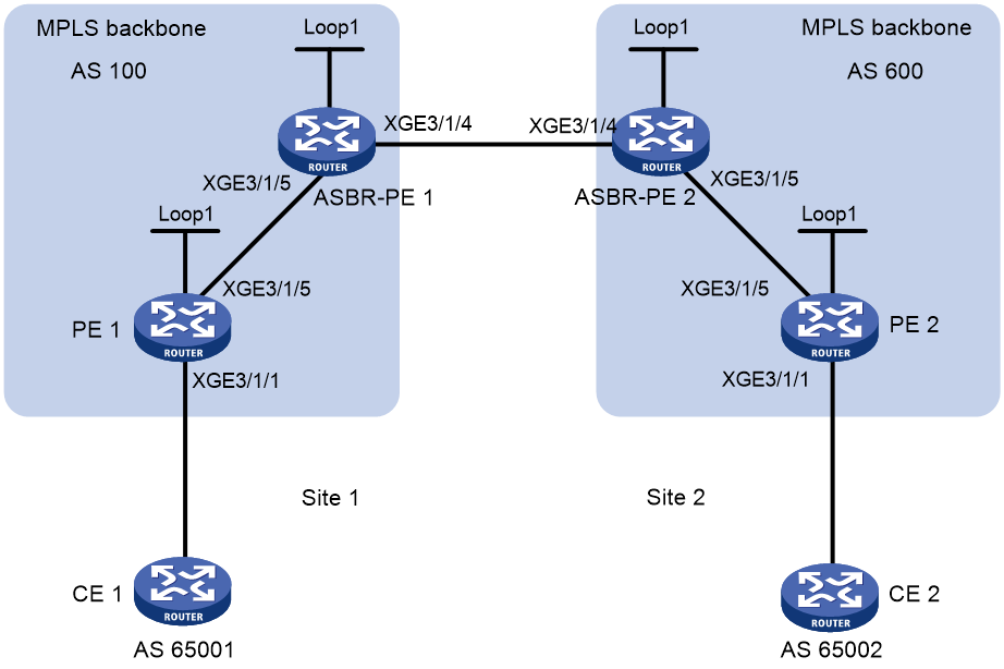
Table 6 Interface and IP address assignment
|
Device |
Interface |
IP address |
Device |
Interface |
IP address |
|
PE 1 |
Loop1 |
2.2.2.9/32 |
PE 2 |
Loop1 |
5.5.5.9/32 |
|
|
XGE3/1/1 |
30.0.0.1/24 |
|
XGE3/1/1 |
20.0.0.1/24 |
|
|
XGE3/1/5 |
1.1.1.2/8 |
|
XGE3/1/5 |
9.1.1.2/8 |
|
ASBR-PE 1 |
Loop1 |
3.3.3.9/32 |
ASBR-PE 2 |
Loop1 |
4.4.4.9/32 |
|
|
XGE3/1/5 |
1.1.1.1/8 |
|
XGE3/1/5 |
9.1.1.1/8 |
|
|
XGE3/1/4 |
11.0.0.2/8 |
|
XGE3/1/4 |
11.0.0.1/8 |
Procedure
1. Configure IP addresses and masks for interfaces. (Details not shown.)
2. Configure PE 1:
# Start OSPF on PE 1, set the LSR ID, and enable MPLS and MPLS TE.
<PE1> system-view
[PE1] ospf 1 router-id 2.2.2.9
[PE1-ospf-1] quit
[PE1] interface ten-gigabitethernet 3/1/5
[PE1-Ten-GigabitEthernet3/1/5] ip address 1.1.1.2 255.0.0.0
[PE1-Ten-GigabitEthernet3/1/5] ospf 1 area 0
[PE1-Ten-GigabitEthernet3/1/5] mpls enable
[PE1-Ten-GigabitEthernet3/1/5] quit
[PE1] interface loopback 1
[PE1-LoopBack1] ip address 2.2.2.9 32
[PE1-LoopBack1] ospf 1 area 0
[PE1-LoopBack1] quit
[PE1] mpls lsr-id 2.2.2.9
[PE1] mpls te
[PE1-te] quit
# Enable SR-MPLS in OSPF view and configure an OSPF prefix SID.
[PE1] ospf 1
[PE1-ospf-1] segment-routing mpls
[PE1-ospf-1] quit
[PE1] interface loopback 1
[PE1-LoopBack1] ospf 1 prefix-sid index 20
[PE1-LoopBack1] quit
# Create VPN instance vpn1, and configure the RD and route target attributes.
[PE1] ip vpn-instance vpn1
[PE1-vpn-instance-vpn1] route-distinguisher 11:11
[PE1-vpn-instance-vpn1] vpn-target 1:1 2:2 3:3 import-extcommunity
[PE1-vpn-instance-vpn1] vpn-target 3:3 export-extcommunity
[PE1-vpn-instance-vpn1] quit
# Associate Ten-GigabitEthernet 3/1/1 with VPN instance vpn1, and assign an IP address to the interface.
[PE1] interface ten-gigabitethernet 3/1/1
[PE1-Ten-GigabitEthernet3/1/1] ip binding vpn-instance vpn1
[PE1-Ten-GigabitEthernet3/1/1] ip address 30.0.0.1 24
[PE1-Ten-GigabitEthernet3/1/1] quit
# Start BGP on PE 1.
[PE1] bgp 100
# Configure peer 3.3.3.9 as a VPNv4 peer.
[PE1-bgp-default] peer 3.3.3.9 as-number 100
[PE1-bgp-default] peer 3.3.3.9 connect-interface loopback 1
[PE1-bgp-default] address-family vpnv4
[PE1-bgp-default-vpnv4] peer 3.3.3.9 enable
[PE1-bgp-default-vpnv4] quit
# Redistribute direct routes to the VPN routing table of vpn1.
[PE1-bgp-default] ip vpn-instance vpn1
[PE1-bgp-default-vpn1] address-family ipv4 unicast
[PE1-bgp-default-ipv4-vpn1] import-route direct
3. Configure ASBR-PE 1:
# Start OSPF on ASBR-PE 1, set the LSR ID, and enable MPLS and MPLS TE.
<ASBR-PE1> system-view
[ASBR-PE1] ospf 1 router-id 3.3.3.9
[ASBR-PE1-ospf-1] quit
[ASBR-PE1] interface ten-gigabitethernet 3/1/4
[ASBR-PE1-Ten-GigabitEthernet3/1/4] mpls enable
[ASBR-PE1-Ten-GigabitEthernet3/1/4] quit
[ASBR-PE1] interface ten-gigabitethernet 3/1/5
[ASBR-PE1-Ten-GigabitEthernet3/1/5] ospf 1 area 0
[ASBR-PE1-Ten-GigabitEthernet3/1/5] mpls enable
[ASBR-PE1-Ten-GigabitEthernet3/1/5] quit
[ASBR-PE1] interface loopback 1
[ASBR-PE1-LoopBack1] ip address 3.3.3.9 32
[ASBR-PE1-LoopBack1] ospf 1 area 0
[ASBR-PE1-LoopBack1] quit
[ASBR-PE1] mpls lsr-id 3.3.3.9
[ASBR-PE1] mpls te
[ASBR-PE1-te] quit
# Enable SR-MPLS in OSPF view and configure an OSPF prefix SID.
[ASBR-PE1] ospf 1
[ASBR-PE1-ospf-1] segment-routing mpls
[ASBR-PE1-ospf-1] quit
[ASBR-PE1] interface loopback 1
[ASBR-PE1-LoopBack1] ospf 1 prefix-sid index 30
[ASBR-PE1-LoopBack1] quit
# Create a routing policy to assign a label.
[ASBR-PE1] route-policy epe permit node 1
[ASBR-PE1-route-policy-epe-1] apply label-value 245555
[ASBR-PE1-route-policy-epe-1] quit
# Start BGP on ASBR-PE 1.
[ASBR-PE1] bgp 100
[ASBR-PE1-bgp-default] peer 2.2.2.9 as-number 100
[ASBR-PE1-bgp-default] peer 2.2.2.9 connect-interface loopback 1
[ASBR-PE1-bgp-default] peer 11.0.0.1 as-number 600
[ASBR-PE1-bgp-default] peer 11.0.0.1 connect-interface ten-gigabitethernet 3/1/4
# Disable route target-based filtering of received VPNv4 routes.
[ASBR-PE1-bgp-default] address-family vpnv4
[ASBR-PE1-bgp-default-vpnv4] undo policy vpn-target
# Configure IBGP peer 2.2.2.9 and EBGP peer 11.0.0.1 as a VPNv4 peer.
[ASBR-PE1-bgp-default-vpnv4] peer 11.0.0.1 enable
[ASBR-PE1-bgp-default-vpnv4] peer 2.2.2.9 enable
[ASBR-PE1-bgp-default-vpnv4] quit
# Enable BGP EPE for EBGP neighbor 11.0.0.1 and specify a routing policy to assign a label to the neighbor.
[ASBR-PE1-bgp-default] peer 11.0.0.1 egress-engineering route-policy epe
[ASBR-PE1-bgp-default] quit
[ASBR-PE1-bgp] quit
4. Configure ASBR-PE 2:
# Start OSPF on ASBR-PE 2, set the LSR ID, and enable MPLS and MPLS TE.
<ASBR-PE2> system-view
[ASBR-PE2] ospf 1 router-id 4.4.4.9
[ASBR-PE2-ospf-1] quit
[ASBR-PE2] interface ten-gigabitethernet 3/1/4
[ASBR-PE2-Ten-GigabitEthernet3/1/4] mpls enable
[ASBR-PE2-Ten-GigabitEthernet3/1/4] quit
[ASBR-PE2] interface ten-gigabitethernet 3/1/5
[ASBR-PE2-Ten-GigabitEthernet3/1/5] ospf 1 area 0
[ASBR-PE2-Ten-GigabitEthernet3/1/5] mpls enable
[ASBR-PE2-Ten-GigabitEthernet3/1/5] quit
[ASBR-PE2] interface loopback 1
[ASBR-PE2-LoopBack1] ip address 4.4.4.9 32
[ASBR-PE2-LoopBack1] ospf 1 area 0
[ASBR-PE2-LoopBack1] quit
[ASBR-PE2] mpls lsr-id 4.4.4.9
[ASBR-PE2] mpls te
[ASBR-PE2-te] quit
# Enable SR-MPLS in OSPF view and configure an OSPF prefix SID.
[ASBR-PE1] ospf 1
[ASBR-PE1-ospf-1] segment-routing mpls
[ASBR-PE1-ospf-1] quit
[ASBR-PE1] interface loopback 1
[ASBR-PE1-LoopBack1] ospf 1 prefix-sid index 40
[ASBR-PE1-LoopBack1] quit
# Create a routing policy to assign a label.
[ASBR-PE2] route-policy epe permit node 1
[ASBR-PE2-route-policy-epe-1] apply label-value 246666
[ASBR-PE2-route-policy-epe-1] quit
# Start BGP on ASBR-PE 2.
[ASBR-PE2] bgp 600
[ASBR-PE2-bgp-default] peer 5.5.5.9 as-number 600
[ASBR-PE2-bgp-default] peer 5.5.5.9 connect-interface loopback 1
[ASBR-PE2-bgp-default] peer 11.0.0.2 as-number 100
[ASBR-PE2-bgp-default] peer 11.0.0.2 connect-interface ten-gigabitethernet 3/1/4
# Disable route target-based filtering of received VPNv4 routes.
[ASBR-PE2-bgp-default] address-family vpnv4
[ASBR-PE2-bgp-default-vpnv4] undo policy vpn-target
# Configure IBGP peer 5.5.5.9 and EBGP peer 11.0.0.2 as a VPNv4 peer.
[ASBR-PE2-bgp-default-vpnv4] peer 11.0.0.2 enable
[ASBR-PE2-bgp-default-vpnv4] peer 5.5.5.9 enable
[ASBR-PE2-bgp-default-vpnv4] quit
# Enable BGP EPE for EBGP neighbor 11.0.0.2 and specify a routing policy to assign a label to the neighbor.
[ASBR-PE2-bgp-default] peer 11.0.0.2 egress-engineering route-policy epe
5. Configure PE 2:
# Start OSPF on PE 2, set the LSR ID, and enable MPLS and MPLS TE.
<PE2> system-view
[PE2] ospf 1 router-id 5.5.5.9
[PE2-ospf-1] quit
[PE2] interface ten-gigabitethernet 3/1/1
[PE2-Ten-GigabitEthernet3/1/1] ospf 1 area 0
[PE2-Ten-GigabitEthernet3/1/1] mpls enable
[PE2-Ten-GigabitEthernet3/1/1] quit
[PE2] interface ten-gigabitethernet 3/1/5
[PE2-Ten-GigabitEthernet3/1/5] ospf 1 area 0
[PE2-Ten-GigabitEthernet3/1/5] mpls enable
[PE2-Ten-GigabitEthernet3/1/5] quit
[PE2] interface loopback 1
[PE2-LoopBack1] ip address 5.5.5.9 32
[PE2-LoopBack1] ospf 1 area 0
[PE2-LoopBack1] quit
[PE2] mpls lsr-id 5.5.5.9
[PE2] mpls te
[PE2-te] quit
# Enable SR-MPLS in OSPF view and configure an OSPF prefix SID.
[PE2] ospf 1
[PE2-ospf-1] segment-routing mpls
[PE2] interface loopback 1
[PE2-LoopBack1] ospf 1 prefix-sid index 50
[PE2-LoopBack1] quit
# Create VPN instance vpn1, and configure the RD and route target attributes.
[PE2] ip vpn-instance vpn1
[PE2-vpn-instance-vpn1] route-distinguisher 11:11
[PE2-vpn-instance-vpn1] vpn-target 1:1 2:2 3:3 import-extcommunity
[PE2-vpn-instance-vpn1] vpn-target 3:3 export-extcommunity
[PE2-vpn-instance-vpn1] quit
# Associate Ten-GigabitEthernet 3/1/1 with VPN instance vpn1, and assign an IP address to the interface.
[PE2] interface ten-gigabitethernet 3/1/1
[PE2-Ten-GigabitEthernet3/1/1] ip binding vpn-instance vpn1
[PE2-Ten-GigabitEthernet3/1/1] ip address 20.0.0.1 24
[PE2-Ten-GigabitEthernet3/1/1] quit
# Start BGP on PE 2.
[PE2] bgp 600
# Configure IBGP peer 4.4.4.9 as a VPNv4 peer.
[PE2-bgp-default] peer 4.4.4.9 as-number 600
[PE2-bgp-default] peer 4.4.4.9 connect-interface loopback 1
[PE2-bgp-default] address-family vpnv4
[PE2-bgp-default-vpnv4] peer 4.4.4.9 enable
[PE2-bgp-default-vpnv4] quit
# Redistribute direct routes to the VPN routing table of vpn1.
[PE2-bgp-default] ip vpn-instance vpn1
[PE2-bgp-default-vpn1] address-family ipv4 unicast
[PE2-bgp-default-ipv4-vpn1] import-route direct
6. Configuring an MPLS TE tunnel:
# Configure ASBR-PE 1 as the ingress node of static SRLSP static-sr-lsp-1 and specify the label that ASBR-PE 1 allocated to ASBR-PE 2 (245555) as the outgoing label.
<ASBR-PE1> system-view
[ASBR-PE1] static-sr-mpls lsp static-sr-lsp-1 out-label 245555
# On ASBR-PE 1, establish static MPLS TE tunnel 1 to ASBR-PE 2. Specify the IP address (11.0.0.1) of the directly connected interface on ASBR-PE 2 as the tunnel destination address. Bind static SRLSP static-sr-lsp-1 to MPLS TE tunnel interface 1.
[ASBR-PE1] interface tunnel 1 mode mpls-te
[ASBR-PE1-Tunnel1] ip address 6.1.1.1 255.255.255.0
[ASBR-PE1-Tunnel1] destination 11.0.0.1
[ASBR-PE1-Tunnel1] mpls te signaling static
[ASBR-PE1-Tunnel1] mpls te static-sr-mpls static-sr-lsp-1
[ASBR-PE1-Tunnel1] quit
# Configure ASBR-PE 2 as the ingress node of static SRLSP static-sr-lsp-2 and specify the label that ASBR-PE 2 allocated to ASBR-PE 1 (246666) as the outgoing label.
<ASBR-PE2> system-view
[ASBR-PE2] static-sr-mpls lsp static-sr-lsp-2 out-label 246666
# On ASBR-PE 2, establish static MPLS TE tunnel 1 to ASBR-PE 1. Specify the IP address (11.0.0.2) of the directly connected interface on ASBR-PE 1 as the tunnel destination address. Bind static SRLSP static-sr-lsp-2 to MPLS TE tunnel interface 1.
[ASBR-PE2] interface tunnel 1 mode mpls-te
[ASBR-PE2-Tunnel1] ip address 7.1.1.1 255.255.255.0
[ASBR-PE2-Tunnel1] destination 11.0.0.2
[ASBR-PE2-Tunnel1] mpls te signaling static
[ASBR-PE2-Tunnel1] mpls te static-sr-mpls static-sr-lsp-2
[ASBR-PE2-Tunnel1] quit
Verifying the configuration
# Execute the display ip routing-table command on CE 1 and CE 2 to verify that they have a route to each other. (Details not shown.)
# Verify that CE 1 and CE 2 can ping each other. (Details not shown.)
# Display MPLS LSP information on ASBR-PE1.
[ASBR-PE1] display mpls lsp
FEC Proto In/Out Label Out Inter/NHLFE/LSINDEX
3.3.3.9/1/53168 StaticCR -/- NHLFE1
11.0.0.1 BGP -/- XGE3/1/4
2.2.2.9/1151 BGP 1151/1151 -
11.0.0.1/1149 BGP 1150/1149 -
11.0.0.1 BGP 245555/- NHLFE1
1.1.1.2 Local -/- XGE3/1/5
11.0.0.1 Local -/- XGE3/1/4
Tunnel1 Local -/- NHLFE4
2.2.2.9/32 OSPF 16020/3 XGE3/1/5
2.2.2.9/32 OSPF -/3 XGE3/1/5
3.3.3.9/32 OSPF 16030/- -
Example: Configuring SR-MPLS inter-AS option C (I) (labeled route exchange in BGP IPv4 unicast address family)
Network configuration
As shown in Figure 27, complete the following tasks:
· Start OSPF and enable OSPF-based SR-MPLS on the PEs in the same AS.
· Configure PE 1 and ASBR-PE 1 to exchange labeled IPv4 routes through IBGP.
· Configure PE 2 and ASBR-PE 2 to exchange labeled IPv4 routes through IBGP.
· Establish an MP-EBGP peer relationship between PE 1 and PE 2 to exchange VPNv4 routes.
· Configure ASBR-PE 1 and ASBR-PE 2 to exchange labeled IPv4 routes through EBGP. Enable BGP-based SR-MPLS.
· Configure dynamic SID allocation on loopback interfaces of the devices. Then, establish an SRLSP based on the allocated SIDs and configure an MPLS TE tunnel over the SRLSP to transmit data.

Table 7 Interface and IP address assignment
|
Device |
Interface |
IP address |
Device |
Interface |
IP address |
|
PE 1 |
Loop1 |
2.2.2.9/32 |
PE 2 |
Loop1 |
5.5.5.9/32 |
|
|
XGE3/1/1 |
30.0.0.1/24 |
|
XGE3/1/1 |
20.0.0.1/24 |
|
|
XGE3/1/5 |
1.1.1.2/8 |
|
XGE3/1/5 |
9.1.1.2/8 |
|
ASBR-PE 1 |
Loop1 |
3.3.3.9/32 |
ASBR-PE 2 |
Loop1 |
4.4.4.9/32 |
|
|
XGE3/1/5 |
1.1.1.1/8 |
|
XGE3/1/5 |
9.1.1.1/8 |
|
|
XGE3/1/4 |
11.0.0.2/8 |
|
XGE3/1/4 |
11.0.0.1/8 |
|
CE 1 |
XGE3/1/1 |
30.0.0.2/24 |
CE 2 |
XGE3/1/1 |
20.0.0.2/24 |
Procedure
1. Configure IP addresses and masks for interfaces. (Details not shown.)
2. Configure CE 1:
# Assign an IP address to interface Ten-GigabitEthernet 3/1/1.
<CE1> system-view
[CE1] interface ten-gigabitethernet 3/1/1
[CE1-Ten-GigabitEthernet3/1/1] ip address 30.0.0.2 24
[CE1-Ten-GigabitEthernet3/1/1] quit
# Configure PE 1 as an EBGP peer and redistribute the VPN route.
[CE1] bgp 65001
[CE1-bgp-default] peer 30.0.0.1 as-number 100
[CE1-bgp-default] address-family ipv4 unicast
[CE1-bgp-default-ipv4] peer 30.0.0.1 enable
[CE1-bgp-default-ipv4] import-route direct
[CE1-bgp-default-ipv4] quit
[CE1-bgp-default] quit
3. Configure PE 1:
# Start OSPF on PE 1, set the LSR ID, and enable MPLS and MPLS TE.
<PE1> system-view
[PE1] ospf 1 router-id 2.2.2.9
[PE1-ospf-1] quit
[PE1] interface ten-gigabitethernet 3/1/1
[PE1-Ten-GigabitEthernet3/1/1] mpls enable
[PE1-Ten-GigabitEthernet3/1/1] quit
[PE1] interface ten-gigabitethernet 3/1/5
[PE1-Ten-GigabitEthernet3/1/5] ospf 1 area 0
[PE1-Ten-GigabitEthernet3/1/5] mpls enable
[PE1-Ten-GigabitEthernet3/1/5] quit
[PE1] interface loopback 1
[PE1-LoopBack1] ip address 2.2.2.9 32
[PE1-LoopBack1] ospf 1 area 0
[PE1-LoopBack1] quit
[PE1] mpls lsr-id 2.2.2.9
[PE1] mpls te
[PE1-te] quit
# Enable SR-MPLS in OSPF view and configure an OSPF prefix SID.
[PE1] ospf 1
[PE1-ospf-1] segment-routing mpls
[PE1-ospf-1] quit
[PE1] interface loopback 1
[PE1-LoopBack1] ospf 1 prefix-sid index 20
[PE1-LoopBack1] quit
# Create VPN instance vpn1. Configure an RD and both import and export route targets for the VPN instance.
[PE1] ip vpn-instance vpn1
[PE1-vpn-instance-vpn1] route-distinguisher 11:11
[PE1-vpn-instance-vpn1] vpn-target 1:1 2:2 3:3 import-extcommunity
[PE1-vpn-instance-vpn1] vpn-target 3:3 export-extcommunity
[PE1-vpn-instance-vpn1] quit
# Bind VPN instance vpn1 to interface Ten-GigabitEthernet 3/1/1 and assign an IP address to the interface.
[PE1] interface ten-gigabitethernet 3/1/1
[PE1-Ten-GigabitEthernet3/1/1] ip binding vpn-instance vpn1
[PE1-Ten-GigabitEthernet3/1/1] ip address 30.0.0.1 24
[PE1-Ten-GigabitEthernet3/1/1] quit
# Start BGP on PE 1.
[PE1] bgp 100
# Enable the capability to exchange labeled routes with IBGP peer 3.3.3.9.
[PE1-bgp-default] peer 3.3.3.9 as-number 100
[PE1-bgp-default] peer 3.3.3.9 connect-interface loopback 1
[PE1-bgp-default] address-family ipv4 unicast
[PE1-bgp-default-ipv4] peer 3.3.3.9 enable
[PE1-bgp-default-ipv4] peer 3.3.3.9 label-route-capability
# Enable SR-MPLS.
[PE1-bgp-default-ipv4] segment-routing mpls
[PE1-bgp-default-ipv4] quit
# Configure the maximum number of hops from PE 1 to EBGP peer 5.5.5.9 as 10.
[PE1-bgp-default] peer 5.5.5.9 as-number 600
[PE1-bgp-default] peer 5.5.5.9 connect-interface loopback 1
[PE1-bgp-default] peer 5.5.5.9 ebgp-max-hop 10
# Configure peer 5.5.5.9 as a VPNv4 peer.
[PE1-bgp-default] address-family vpnv4
[PE1-bgp-default-vpnv4] peer 5.5.5.9 enable
[PE1-bgp-default-vpnv4] quit
# Configure CE 1 as an EBGP peer of PE 1 and install the learned BGP routes in the routing table of the VPN instance.
[PE1-bgp-default] address-family vpnv4
4. Configure ASBR-PE 1:
# Start OSPF on ASBR-PE 1, set the LSR ID, and enable MPLS and MPLS TE.
<ASBR-PE1> system-view
[ASBR-PE1] ospf 1 router-id 3.3.3.9
[ASBR-PE1-ospf-1] quit
[ASBR-PE1] interface ten-gigabitethernet 3/1/4
[ASBR-PE1-Ten-GigabitEthernet3/1/4] mpls enable
[ASBR-PE1-Ten-GigabitEthernet3/1/4] quit
[ASBR-PE1] interface ten-gigabitethernet 3/1/5
[ASBR-PE1-Ten-GigabitEthernet3/1/5] ospf 1 area 0
[ASBR-PE1-Ten-GigabitEthernet3/1/5] mpls enable
[ASBR-PE1-Ten-GigabitEthernet3/1/5] quit
[ASBR-PE1] interface loopback 1
[ASBR-PE1-LoopBack1] ip address 3.3.3.9 32
[ASBR-PE1-LoopBack1] ospf 1 area 0
[ASBR-PE1-LoopBack1] quit
[ASBR-PE1] mpls lsr-id 3.3.3.9
[ASBR-PE1] mpls te
[ASBR-PE1-te] quit
# Enable SR-MPLS in OSPF view and configure an OSPF prefix SID.
[ASBR-PE1] ospf 1
[ASBR-PE1-ospf-1] segment-routing mpls
[ASBR-PE1-ospf-1] quit
[ASBR-PE1] interface loopback 1
[ASBR-PE1-LoopBack1] ospf 1 prefix-sid index 30
[ASBR-PE1-LoopBack1] quit
# Create a routing policy and specify a label index value.
[ASBR-PE1]ip prefix-list 1 permit 2.2.2.9 32
[ASBR-PE1]route-policy policy1 permit node 1
[ASBR-PE1-route-policy-policy1-1] if-match ip address prefix-list 1
[ASBR-PE1-route-policy-policy1-1] apply label-index 20
[ASBR-PE1-route-policy-policy1-1] quit
# Start BGP on ASBR-PE 1. Enable the capability to exchange labeled routes with IBGP peer 2.2.2.9.
[ASBR-PE1] bgp 100
[ASBR-PE1-bgp-default] peer 2.2.2.9 as-number 100
[ASBR-PE1-bgp-default] peer 2.2.2.9 connect-interface loopback 1
[ASBR-PE1-bgp-default] address-family ipv4 unicast
[ASBR-PE1-bgp-default-ipv4] peer 2.2.2.9 enable
[ASBR-PE1-bgp-default-ipv4] peer 2.2.2.9 label-route-capability
# Redistribute routes from OSPF process 1 to BGP and apply the routing policy.
[ASBR-PE1-bgp-default-ipv4] import-route ospf 1 route-policy policy1
# Enable SR-MPLS.
[ASBR-PE1-bgp-default-ipv4] segment-routing mpls
[ASBR-PE1-bgp-default-ipv4] quit
# Enable the capability to exchange labeled routes with EBGP peer 11.0.0.1.
[ASBR-PE1-bgp-default] peer 11.0.0.1 as-number 600
[ASBR-PE1-bgp-default] address-family ipv4 unicast
[ASBR-PE1-bgp-default-ipv4] peer 11.0.0.1 enable
[ASBR-PE1-bgp-default-ipv4] peer 11.0.0.1 label-route-capability
5. Configure ASBR-PE 2:
# Start OSPF on ASBR-PE 2, set the LSR ID, and enable MPLS and MPLS TE.
<ASBR-PE2> system-view
[ASBR-PE2] ospf 1 router-id 4.4.4.9
[ASBR-PE2-ospf-1] quit
[ASBR-PE2] interface ten-gigabitethernet 3/1/4
[ASBR-PE2-Ten-GigabitEthernet3/1/4] mpls enable
[ASBR-PE2-Ten-GigabitEthernet3/1/4] quit
[ASBR-PE2] interface ten-gigabitethernet 3/1/5
[ASBR-PE2-Ten-GigabitEthernet3/1/5] ospf 1 area 0
[ASBR-PE2-Ten-GigabitEthernet3/1/5] mpls enable
[ASBR-PE2-Ten-GigabitEthernet3/1/5] quit
[ASBR-PE2] interface loopback 1
[ASBR-PE2-LoopBack1] ip address 4.4.4.9 32
[ASBR-PE2-LoopBack1] ospf 1 area 0
[ASBR-PE2-LoopBack1] quit
[ASBR-PE2] mpls lsr-id 4.4.4.9
[ASBR-PE2] mpls te
[ASBR-PE2-te] quit
# Enable SR-MPLS in OSPF view and configure an OSPF prefix SID.
[ASBR-PE2] ospf 1
[ASBR-PE2-ospf-1] segment-routing mpls
[ASBR-PE2-ospf-1] quit
[ASBR-PE2] interface loopback 1
[ASBR-PE2-LoopBack1] ospf 1 prefix-sid index 40
[ASBR-PE2-LoopBack1] quit
# Create a routing policy and specify a label index value.
[ASBR-PE2]ip prefix-list 1 permit 5.5.5.9 32
[ASBR-PE2] route-policy policy1 permit node 1
[ASBR-PE2-route-policy-policy1-1] if-match ip address prefix-list 1
[ASBR-PE2-route-policy-policy1-1] apply label-index 50
[ASBR-PE2-route-policy-policy1-1] quit
# Start BGP on ASBR-PE 2. Enable the capability to exchange labeled routes with IBGP peer 5.5.5.9.
[ASBR-PE2] bgp 600
[ASBR-PE2-bgp-default] peer 5.5.5.9 as-number 600
[ASBR-PE2-bgp-default] peer 5.5.5.9 connect-interface loopback 1
[ASBR-PE2-bgp-default] address-family ipv4 unicast
[ASBR-PE2-bgp-default-ipv4] peer 5.5.5.9 enable
[ASBR-PE2-bgp-default-ipv4] peer 5.5.5.9 label-route-capability
# Redistribute routes from OSPF process 1 to BGP and apply the routing policy.
[ASBR-PE2-bgp-default-ipv4] import-route ospf 1 route-policy policy1
# Enable SR-MPLS.
[ASBR-PE2-bgp-default-ipv4] segment-routing mpls
[ASBR-PE2-bgp-default-ipv4] quit
# Enable the capability to exchange labeled routes with EBGP peer 11.0.0.2.
[ASBR-PE2-bgp-default] peer 11.0.0.2 as-number 100
[ASBR-PE2-bgp-default] address-family ipv4 unicast
[ASBR-PE2-bgp-default-ipv4] peer 11.0.0.2 enable
[ASBR-PE2-bgp-default-ipv4] peer 11.0.0.2 label-route-capability
6. Configure PE 2:
# Start OSPF on PE 2, set the LSR ID, and enable MPLS and MPLS TE.
<PE2> system-view
[PE2] ospf 1 router-id 5.5.5.9
[PE2-ospf-1] quit
[PE2] interface ten-gigabitethernet 3/1/1
[PE2-Ten-GigabitEthernet3/1/1] mpls enable
[PE2-Ten-GigabitEthernet3/1/1] quit
[PE2] interface ten-gigabitethernet 3/1/5
[PE2-Ten-GigabitEthernet3/1/5] ospf 1 area 0
[PE2-Ten-GigabitEthernet3/1/5] mpls enable
[PE2-Ten-GigabitEthernet3/1/5] quit
[PE2] interface loopback 1
[PE2-LoopBack1] ip address 5.5.5.9 32
[PE2-LoopBack1] ospf 1 area 0
[PE2-LoopBack1] quit
[PE2] mpls lsr-id 5.5.5.9
[PE2] mpls te
[PE2-te] quit
# Enable SR-MPLS in OSPF view and configure an OSPF prefix SID.
[PE2] ospf 1
[PE2-ospf-1] segment-routing mpls
[PE2-ospf-1] quit
[PE2] interface loopback 1
[PE2-LoopBack1] ospf 1 prefix-sid index 50
[PE2-LoopBack1] quit
# Create VPN instance vpn1, and configure the RD and route target attributes.
[PE2] ip vpn-instance vpn1
[PE2-vpn-instance-vpn1] route-distinguisher 11:11
[PE2-vpn-instance-vpn1] vpn-target 1:1 2:2 3:3 import-extcommunity
[PE2-vpn-instance-vpn1] vpn-target 3:3 export-extcommunity
[PE2-vpn-instance-vpn1] quit
# Associate Ten-GigabitEthernet 3/1/1 with VPN instance vpn1, and assign an IP address to the interface.
[PE2] interface ten-gigabitethernet 3/1/1
[PE2-Ten-GigabitEthernet3/1/1] ip binding vpn-instance vpn1
[PE2-Ten-GigabitEthernet3/1/1] ip address 20.0.0.1 24
[PE2-Ten-GigabitEthernet3/1/1] quit
# Start BGP on PE 2.
[PE2] bgp 600
# Enable the capability to exchange labeled routes with IBGP peer 4.4.4.9.
[PE2-bgp-default] peer 4.4.4.9 as-number 600
[PE2-bgp-default] peer 4.4.4.9 connect-interface loopback 1
[PE2-bgp-default] address-family ipv4 unicast
[PE2-bgp-default-ipv4] peer 4.4.4.9 enable
[PE2-bgp-default-ipv4] peer 4.4.4.9 label-route-capability
# Enable SR-MPLS.
[PE2-bgp-default-ipv4] segment-routing mpls
[PE2-bgp-default-ipv4] quit
# Configure the maximum number of hops from PE 2 to EBGP peer 2.2.2.9 as 10.
[PE2-bgp-default] peer 2.2.2.9 as-number 100
[PE2-bgp-default] peer 2.2.2.9 connect-interface loopback 1
[PE2-bgp-default] peer 2.2.2.9 ebgp-max-hop 10
# Configure peer 2.2.2.9 as a VPNv4 peer.
[PE2-bgp-default] address-family vpnv4
[PE2-bgp-default-vpnv4] peer 2.2.2.9 enable
[PE2-bgp-default-vpnv4] quit
# Configure CE 2 as an EBGP peer and install the learned BGP route in the routing table of the VPN instance.
[PE2-bgp-default] ip vpn-instance vpn1
[PE2-bgp-default-vpn1] peer 20.0.0.2 as-number 65002
[PE2-bgp-default-vpn1] address-family ipv4 unicast
[PE2-bgp-default-ipv4-vpn1] peer 20.0.0.2 enable
7. Configure CE 2:
# Assign an IP address to interface Ten-GigabitEthernet 3/1/1.
<CE2> system-view
[CE2] interface ten-gigabitethernet 3/1/1
[CE2-Ten-GigabitEthernet3/1/1] ip address 20.0.0.2 24
[CE2-Ten-GigabitEthernet3/1/1] quit
# Establish an EBGP peer relationship with PE 2, and redistribute VPN routes.
[CE2] bgp 65002
[CE2-bgp-default] peer 20.0.0.1 as-number 600
[CE2-bgp-default] address-family ipv4 unicast
[CE2-bgp-default-ipv4] peer 20.0.0.1 enable
[CE2-bgp-default-ipv4] import-route direct
Verifying the configuration
# Execute the display ip routing-table command on CE 1 and CE 2 to verify that they have a route to each other. (Details not shown.)
# Verify that CE 1 and CE 2 can ping each other. (Details not shown.)
# Display MPLS LSP information on PE 1.
[PE1] display mpls lsp
FEC Proto In/Out Label Out Inter/NHLFE/LSINDEX
2.2.2.9/32 BGP -/16020 NHLFE1
5.5.5.9/32 BGP -/16050 NHLFE1
5.5.5.9 BGP -/- XGE3/1/5
1.1.1.1 Local -/- XGE3/1/5
2.2.2.9/32 OSPF 16020/- -
3.3.3.9/32 OSPF 16030/3 XGE3/1/5
3.3.3.9/32 OSPF -/3 XGE3/1/5
Example: Configuring SR-MPLS inter-AS option C (I) (labeled route exchange in BGP IPv4 labeled unicast address family)
Network configuration
As shown in Figure 28, complete the following tasks:
· Start OSPF and enable OSPF-based SR-MPLS on the PEs in the same AS.
· Configure PE 1 and ASBR-PE 1 to exchange labeled IPv4 routes through IBGP in the BGP IPv4 labeled unicast address family.
· Configure PE 2 and ASBR-PE 2 to exchange labeled IPv4 routes through IBGP in the BGP IPv4 labeled unicast address family.
· Establish an MP-EBGP peer relationship between PE 1 and PE 2 to exchange VPNv4 routes.
· Configure ASBR-PE 1 and ASBR-PE 2 to exchange labeled IPv4 routes through EBGP in the BGP IPv4 labeled unicast address family and enable BGP-based SR-MPLS on the two devices.
· Configure dynamic SID allocation on loopback interfaces of the devices. Then, establish an SRLSP based on the allocated SIDs and configure an MPLS TE tunnel over the SRLSP to transmit data.
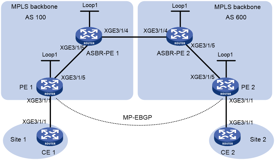
Table 8 Interface and IP address assignment
|
Device |
Interface |
IP address |
Device |
Interface |
IP address |
|
PE 1 |
Loop1 |
2.2.2.9/32 |
PE 2 |
Loop1 |
5.5.5.9/32 |
|
|
XGE3/1/1 |
30.0.0.1/24 |
|
XGE3/1/1 |
20.0.0.1/24 |
|
|
XGE3/1/5 |
1.1.1.2/8 |
|
XGE3/1/5 |
9.1.1.2/8 |
|
ASBR-PE 1 |
Loop1 |
3.3.3.9/32 |
ASBR-PE 2 |
Loop1 |
4.4.4.9/32 |
|
|
XGE3/1/5 |
1.1.1.1/8 |
|
XGE3/1/5 |
9.1.1.1/8 |
|
|
XGE3/1/4 |
11.0.0.2/8 |
|
XGE3/1/4 |
11.0.0.1/8 |
|
CE 1 |
XGE3/1/1 |
30.0.0.2/24 |
CE 2 |
XGE3/1/1 |
20.0.0.2/24 |
Procedure
1. Configure IP addresses and masks for interfaces. (Details not shown.)
2. Configure CE 1:
# Assign an IP address to interface Ten-GigabitEthernet 3/1/1.
<CE1> system-view
[CE1] interface ten-gigabitethernet 3/1/1
[CE1-Ten-GigabitEthernet3/1/1] ip address 30.0.0.2 24
[CE1-Ten-GigabitEthernet3/1/1] quit
# Configure PE 1 as an EBGP peer and redistribute the VPN route.
[CE1] bgp 65001
[CE1-bgp-default] peer 30.0.0.1 as-number 100
[CE1-bgp-default] address-family ipv4 unicast
[CE1-bgp-default-ipv4] peer 30.0.0.1 enable
[CE1-bgp-default-ipv4] import-route direct
[CE1-bgp-default-ipv4] quit
[CE1-bgp-default] quit
3. Configure PE 1:
# Start OSPF on PE 1, set the LSR ID, and enable MPLS and MPLS TE.
<PE1> system-view
[PE1] ospf 1 router-id 2.2.2.9
[PE1-ospf-1] quit
[PE1] interface ten-gigabitethernet 3/1/1
[PE1-Ten-GigabitEthernet3/1/1] mpls enable
[PE1-Ten-GigabitEthernet3/1/1] quit
[PE1] interface ten-gigabitethernet 3/1/5
[PE1-Ten-GigabitEthernet3/1/5] ospf 1 area 0
[PE1-Ten-GigabitEthernet3/1/5] mpls enable
[PE1-Ten-GigabitEthernet3/1/5] quit
[PE1] interface loopback 1
[PE1-LoopBack1] ip address 2.2.2.9 32
[PE1-LoopBack1] ospf 1 area 0
[PE1-LoopBack1] quit
[PE1] mpls lsr-id 2.2.2.9
[PE1] mpls te
[PE1-te] quit
# Enable SR-MPLS in OSPF view and configure an OSPF prefix SID.
[PE1] ospf 1
[PE1-ospf-1] segment-routing mpls
[PE1-ospf-1] quit
[PE1] interface loopback 1
[PE1-LoopBack1] ospf 1 prefix-sid index 20
[PE1-LoopBack1] quit
# Create VPN instance vpn1. Configure an RD and both import and export route targets for the VPN instance.
[PE1] ip vpn-instance vpn1
[PE1-vpn-instance-vpn1] route-distinguisher 11:11
[PE1-vpn-instance-vpn1] vpn-target 1:1 2:2 3:3 import-extcommunity
[PE1-vpn-instance-vpn1] vpn-target 3:3 export-extcommunity
[PE1-vpn-instance-vpn1] quit
# Bind VPN instance vpn1 to interface Ten-GigabitEthernet 3/1/1 and assign an IP address to the interface.
[PE1] interface ten-gigabitethernet 3/1/1
[PE1-Ten-GigabitEthernet3/1/1] ip binding vpn-instance vpn1
[PE1-Ten-GigabitEthernet3/1/1] ip address 30.0.0.1 24
[PE1-Ten-GigabitEthernet3/1/1] quit
# Start BGP on PE 1.
[PE1] bgp 100
# Enable the capability to exchange labeled routes with IBGP peer 3.3.3.9.
[PE1-bgp-default] peer 3.3.3.9 as-number 100
[PE1-bgp-default] peer 3.3.3.9 connect-interface loopback 1
[PE1-bgp-default] address-family ipv4 labeled-unicast
[PE1-bgp-default-labeled-ipv4] peer 3.3.3.9 enable
# Enable SR-MPLS.
[PE1-bgp-default-labeled-ipv4] segment-routing mpls
[PE1-bgp-default-labeled-ipv4] quit
# Redistribute the BGP routes in the BGP IPv4 labeled unicast address family to the BGP routing table in the BGP IPv4 unicast address family, and add the redistributed BGP routes to the public routing table.
[PE1-bgp-default] address-family ipv4 unicast
[PE1-bgp-default-ipv4] import-rib public labeled-unicast
[PE1-bgp-default-ipv4] quit
# Configure the maximum number of hops from PE 1 to EBGP peer 5.5.5.9 as 10.
[PE1-bgp-default] peer 5.5.5.9 as-number 600
[PE1-bgp-default] peer 5.5.5.9 connect-interface loopback 1
[PE1-bgp-default] peer 5.5.5.9 ebgp-max-hop 10
# Configure peer 5.5.5.9 as a VPNv4 peer.
[PE1-bgp-default] address-family vpnv4
[PE1-bgp-default-vpnv4] peer 5.5.5.9 enable
[PE1-bgp-default-vpnv4] quit
# Configure CE 1 as an EBGP peer of PE 1 and install the learned BGP routes in the routing table of the VPN instance.
[PE1-bgp-default] ip vpn-instance vpn1
[PE1-bgp-default-vpn1] peer 30.0.0.2 as-number 65001
[PE1-bgp-default-vpn1] address-family ipv4 unicast
[PE1-bgp-default-ipv4-vpn1] peer 30.0.0.2 enable
[PE1-bgp-default-ipv4-vpn1] quit
[PE1-bgp-default-vpn1] quit
[PE1-bgp-default] quit
4. Configure ASBR-PE 1:
# Start OSPF on ASBR-PE 1, set the LSR ID, and enable MPLS and MPLS TE.
<ASBR-PE1> system-view
[ASBR-PE1] ospf 1 router-id 3.3.3.9
[ASBR-PE1-ospf-1] quit
[ASBR-PE1] interface ten-gigabitethernet 3/1/4
[ASBR-PE1-Ten-GigabitEthernet3/1/4] mpls enable
[ASBR-PE1-Ten-GigabitEthernet3/1/4] quit
[ASBR-PE1] interface ten-gigabitethernet 3/1/5
[ASBR-PE1-Ten-GigabitEthernet3/1/5] ospf 1 area 0
[ASBR-PE1-Ten-GigabitEthernet3/1/5] mpls enable
[ASBR-PE1-Ten-GigabitEthernet3/1/5] quit
[ASBR-PE1] interface loopback 1
[ASBR-PE1-LoopBack1] ip address 3.3.3.9 32
[ASBR-PE1-LoopBack1] ospf 1 area 0
[ASBR-PE1-LoopBack1] quit
[ASBR-PE1] mpls lsr-id 3.3.3.9
[ASBR-PE1] mpls te
[ASBR-PE1-te] quit
# Enable SR-MPLS in OSPF view and configure an OSPF prefix SID.
[ASBR-PE1] ospf 1
[ASBR-PE1-ospf-1] segment-routing mpls
[ASBR-PE1-ospf-1] quit
[ASBR-PE1] interface loopback 1
[ASBR-PE1-LoopBack1] ospf 1 prefix-sid index 30
[ASBR-PE1-LoopBack1] quit
# Create a routing policy and specify a label index value.
[ASBR-PE1]ip prefix-list 1 permit 2.2.2.9 32
[ASBR-PE1]route-policy policy1 permit node 1
[ASBR-PE1-route-policy-policy1-1] if-match ip address prefix-list 1
[ASBR-PE1-route-policy-policy1-1] apply label-index 20
[ASBR-PE1-route-policy-policy1-1] quit
# Start BGP on ASBR-PE 1. Configure peer 2.2.2.9 and peer 11.0.0.1 as BGP IPv4 labeled unicast peers.
[ASBR-PE1] bgp 100
[ASBR-PE1-bgp-default] peer 2.2.2.9 as-number 100
[ASBR-PE1-bgp-default] peer 2.2.2.9 connect-interface loopback 1
[ASBR-PE1-bgp-default] peer 11.0.0.1 as-number 600
[ASBR-PE1-bgp-default] address-family ipv4 labeled-unicast
[ASBR-PE1-bgp-default-labeled-ipv4] peer 2.2.2.9 enable
[ASBR-PE1-bgp-default-labeled-ipv4] peer 11.0.0.1 enable
# Redistribute routes from OSPF process 1 to BGP and apply the routing policy.
[ASBR-PE1-bgp-default-labeled-ipv4] import-route ospf 1 route-policy policy1
# Enable SR-MPLS.
[ASBR-PE1-bgp-default-labeled-ipv4] segment-routing mpls
[ASBR-PE1-bgp-default-labeled-ipv4] quit
[ASBR-PE1-bgp-default] quit
5. Configure ASBR-PE 2:
# Start OSPF on ASBR-PE 2, set the LSR ID, and enable MPLS and MPLS TE.
<ASBR-PE2> system-view
[ASBR-PE2] ospf 1 router-id 4.4.4.9
[ASBR-PE2-ospf-1] quit
[ASBR-PE2] interface ten-gigabitethernet 3/1/4
[ASBR-PE2-Ten-GigabitEthernet3/1/4] mpls enable
[ASBR-PE2-Ten-GigabitEthernet3/1/4] quit
[ASBR-PE2] interface ten-gigabitethernet 3/1/5
[ASBR-PE2-Ten-GigabitEthernet3/1/5] ospf 1 area 0
[ASBR-PE2-Ten-GigabitEthernet3/1/5] mpls enable
[ASBR-PE2-Ten-GigabitEthernet3/1/5] quit
[ASBR-PE2] interface loopback 1
[ASBR-PE2-LoopBack1] ip address 4.4.4.9 32
[ASBR-PE2-LoopBack1] ospf 1 area 0
[ASBR-PE2-LoopBack1] quit
[ASBR-PE2] mpls lsr-id 4.4.4.9
[ASBR-PE2] mpls te
[ASBR-PE2-te] quit
# Enable SR-MPLS in OSPF view and configure an OSPF prefix SID.
[ASBR-PE2] ospf 1
[ASBR-PE2-ospf-1] segment-routing mpls
[ASBR-PE2-ospf-1] quit
[ASBR-PE2] interface loopback 1
[ASBR-PE2-LoopBack1] ospf 1 prefix-sid index 40
[ASBR-PE2-LoopBack1] quit
# Create a routing policy and specify a label index value.
[ASBR-PE2]ip prefix-list 1 permit 5.5.5.9 32
[ASBR-PE2] route-policy policy1 permit node 1
[ASBR-PE2-route-policy-policy1-1] if-match ip address prefix-list 1
[ASBR-PE2-route-policy-policy1-1] apply label-index 50
[ASBR-PE2-route-policy-policy1-1] quit
# Start BGP on ASBR-PE 2. Configure peer 5.5.5.9 and peer 11.0.0.2 as BGP IPv4 labeled unicast peers.
[ASBR-PE2] bgp 600
[ASBR-PE2-bgp-default] peer 5.5.5.9 as-number 600
[ASBR-PE2-bgp-default] peer 5.5.5.9 connect-interface loopback 1
[ASBR-PE2-bgp-default] peer 11.0.0.2 as-number 100
[ASBR-PE2-bgp-default] address-family ipv4 labeled-unicast
[ASBR-PE2-bgp-default-labeled-ipv4] peer 5.5.5.9 enable
[ASBR-PE2-bgp-default-labeled-ipv4] peer 11.0.0.2 enable
# Redistribute routes from OSPF process 1 to BGP and apply the routing policy.
[ASBR-PE2-bgp-default-labeled-ipv4] import-route ospf 1 route-policy policy1
# Enable SR-MPLS.
[ASBR-PE2-bgp-default-labeled-ipv4] segment-routing mpls
[ASBR-PE2-bgp-default-labeled-ipv4] quit
[ASBR-PE2-bgp-default] quit
6. Configure PE 2:
# Start OSPF on PE 2, set the LSR ID, and enable MPLS and MPLS TE.
<PE2> system-view
[PE2] ospf 1 router-id 5.5.5.9
[PE2-ospf-1] quit
[PE2] interface ten-gigabitethernet 3/1/1
[PE2-Ten-GigabitEthernet3/1/1] mpls enable
[PE2-Ten-GigabitEthernet3/1/1] quit
[PE2] interface ten-gigabitethernet 3/1/5
[PE2-Ten-GigabitEthernet3/1/5] ospf 1 area 0
[PE2-Ten-GigabitEthernet3/1/5] mpls enable
[PE2-Ten-GigabitEthernet3/1/5] quit
[PE2] interface loopback 1
[PE2-LoopBack1] ip address 5.5.5.9 32
[PE2-LoopBack1] ospf 1 area 0
[PE2-LoopBack1] quit
[PE2] mpls lsr-id 5.5.5.9
[PE2] mpls te
[PE2-te] quit
# Enable SR-MPLS in OSPF view and configure an OSPF prefix SID.
[PE2] ospf 1
[PE2-ospf-1] segment-routing mpls
[PE2-ospf-1] quit
[PE2] interface loopback 1
[PE2-LoopBack1] ospf 1 prefix-sid index 50
[PE2-LoopBack1] quit
# Create VPN instance vpn1, and configure the RD and route target attributes.
[PE2] ip vpn-instance vpn1
[PE2-vpn-instance-vpn1] route-distinguisher 11:11
[PE2-vpn-instance-vpn1] vpn-target 1:1 2:2 3:3 import-extcommunity
[PE2-vpn-instance-vpn1] vpn-target 3:3 export-extcommunity
[PE2-vpn-instance-vpn1] quit
# Associate Ten-GigabitEthernet 3/1/1 with VPN instance vpn1, and assign an IP address to the interface.
[PE2] interface ten-gigabitethernet 3/1/1
[PE2-Ten-GigabitEthernet3/1/1] ip binding vpn-instance vpn1
[PE2-Ten-GigabitEthernet3/1/1] ip address 20.0.0.1 24
[PE2-Ten-GigabitEthernet3/1/1] quit
# Start BGP on PE 2. Configure IBGP peer 4.4.4.9 as a BGP IPv4 labeled unicast peer.
[PE2] bgp 600
[PE2-bgp-default] peer 4.4.4.9 as-number 600
[PE2-bgp-default] peer 4.4.4.9 connect-interface loopback 1
[PE2-bgp-default] address-family ipv4 labeled-unicast
[PE2-bgp-default] peer 4.4.4.9 enable
[PE2-bgp-default-labeled-ipv4] peer 4.4.4.9
# Enable SR-MPLS.
[PE2-bgp-default-labeled-ipv4] segment-routing mpls
[PE2-bgp-default-labeled-ipv4] quit
# Redistribute the BGP routes in the BGP IPv4 labeled unicast address family to the BGP routing table in the BGP IPv4 unicast address family, and add the redistributed BGP routes to the public routing table.
[PE2-bgp-default] address-family ipv4 unicast
[PE2-bgp-default-ipv4] import-rib public labeled-unicast
[PE2-bgp-default-ipv4] quit
# Configure the maximum number of hops from PE 2 to EBGP peer 2.2.2.9 as 10.
[PE2-bgp-default] peer 2.2.2.9 as-number 100
[PE2-bgp-default] peer 2.2.2.9 connect-interface loopback 1
[PE2-bgp-default] peer 2.2.2.9 ebgp-max-hop 10
# Configure peer 2.2.2.9 as a VPNv4 peer.
[PE2-bgp-default] address-family vpnv4
[PE2-bgp-default-vpnv4] peer 2.2.2.9 enable
[PE2-bgp-default-vpnv4] quit
# Configure CE 2 as an EBGP peer and install the learned BGP route in the routing table of the VPN instance.
[PE2-bgp-default] ip vpn-instance vpn1
[PE2-bgp-default-vpn1] peer 20.0.0.2 as-number 65002
[PE2-bgp-default-vpn1] address-family ipv4 unicast
[PE2-bgp-default-ipv4-vpn1] peer 20.0.0.2 enable
7. Configure CE 2:
# Assign an IP address to interface Ten-GigabitEthernet 3/1/1.
<CE2> system-view
[CE2] interface ten-gigabitethernet 3/1/1
[CE2-Ten-GigabitEthernet3/1/1] ip address 20.0.0.2 24
[CE2-Ten-GigabitEthernet3/1/1] quit
# Establish an EBGP peer relationship with PE 2, and redistribute VPN routes.
[CE2] bgp 65002
[CE2-bgp-default] peer 20.0.0.1 as-number 600
[CE2-bgp-default] address-family ipv4 unicast
[CE2-bgp-default-ipv4] peer 20.0.0.1 enable
[CE2-bgp-default-ipv4] import-route direct
[CE2-bgp-default-ipv4] quit
[CE2-bgp-default] quit
Verifying the configuration
# Execute the display ip routing-table command on CE 1 and CE 2 to verify that they have a route to each other. (Details not shown.)
# Verify that CE 1 and CE 2 can ping each other. (Details not shown.)
# Display MPLS LSP information on PE 1.
[PE1] display mpls lsp
FEC Proto In/Out Label Out Inter/NHLFE/LSINDEX
2.2.2.9/32 BGP -/16020 NHLFE1
5.5.5.9/32 BGP -/16050 NHLFE1
5.5.5.9 BGP -/- XGE3/1/5
1.1.1.1 Local -/- XGE3/1/5
2.2.2.9/32 OSPF 16020/- -
3.3.3.9/32 OSPF 16030/3 XGE3/1/5
3.3.3.9/32 OSPF -/3 XGE3/1/5
Example: Configuring SR-MPLS inter-AS option C (II) (labeled route exchange in BGP IPv4 unicast address family)
Network configuration
As shown in Figure 29, complete the following tasks:
· Start OSPF and enable OSPF-based SR-MPLS on the PEs in the same AS.
· Configure PE 1 and ASBR-PE 1 to exchange labeled IPv4 routes through IBGP. Enable BGP-based SR-MPLS.
· Configure PE 2 and ASBR-PE 2 to exchange labeled IPv4 routes through IBGP. Enable BGP-based SR-MPLS.
· Establish an MP-EBGP peer relationship between PE 1 and PE 2 to exchange VPNv4 routes.
· Configure ASBR-PE 1 and ASBR-PE 2 to exchange labeled IPv4 routes through EBGP. Enable BGP-based SR-MPLS.
· Configure dynamic SID allocation on loopback interfaces of the devices. Then, establish an SRLSP based on the allocated SIDs and configure an MPLS TE tunnel over the SRLSP to transmit data.

Table 9 Interface and IP address assignment
|
Device |
Interface |
IP address |
Device |
Interface |
IP address |
|
PE 1 |
Loop1 |
2.2.2.9/32 |
PE 2 |
Loop1 |
5.5.5.9/32 |
|
|
XGE3/1/1 |
30.0.0.1/24 |
|
XGE3/1/1 |
20.0.0.1/24 |
|
|
XGE3/1/5 |
1.1.1.2/8 |
|
XGE3/1/5 |
9.1.1.2/8 |
|
ASBR-PE 1 |
Loop1 |
3.3.3.9/32 |
ASBR-PE 2 |
Loop1 |
4.4.4.9/32 |
|
|
XGE3/1/5 |
1.1.1.1/8 |
|
XGE3/1/5 |
9.1.1.1/8 |
|
|
XGE3/1/4 |
11.0.0.2/8 |
|
XGE3/1/4 |
11.0.0.1/8 |
|
CE 1 |
XGE3/1/1 |
30.0.0.2/24 |
CE 2 |
XGE3/1/1 |
20.0.0.2/24 |
Procedure
1. Configure IP addresses and masks for interfaces. (Details not shown.)
2. Configure CE 1:
# Assign an IP address to interface Ten-GigabitEthernet 3/1/1.
<CE1> system-view
[CE1] interface ten-gigabitethernet 3/1/1
[CE1-Ten-GigabitEthernet3/1/1] ip address 30.0.0.2 24
[CE1-Ten-GigabitEthernet3/1/1] quit
# Establish an EBGP peer relationship with PE 1, and redistribute VPN routes.
[CE1] bgp 65001
[CE1-bgp-default] peer 30.0.0.1 as-number 100
[CE1-bgp-default] address-family ipv4 unicast
[CE1-bgp-default-ipv4] peer 30.0.0.1 enable
[CE1-bgp-default-ipv4] import-route direct
[CE1-bgp-default-ipv4] quit
[CE1-bgp-default] quit
3. Configure PE 1:
# Start OSPF on PE 1, set the LSR ID, and enable MPLS and MPLS TE.
<PE1> system-view
[PE1] ospf 1 router-id 2.2.2.9
[PE1-ospf-1] quit
[PE1] interface ten-gigabitethernet 3/1/1
[PE1-Ten-GigabitEthernet3/1/1] ospf 1 area 0
[PE1-Ten-GigabitEthernet3/1/1] mpls enable
[PE1-Ten-GigabitEthernet3/1/1] quit
[PE1] interface loopback 1
[PE1-LoopBack1] ip address 2.2.2.9 32
[PE1-LoopBack1] ospf 1 area 0
[PE1-LoopBack1] quit
[PE1] mpls lsr-id 2.2.2.9
[PE1] mpls te
[PE1-te] quit
# Assign an IP address to Ten-GigabitEthernet 3/1/5. Start OSPF and enable MPLS on the interface.
[PE1] interface ten-gigabitethernet 3/1/5
[PE1-Ten-GigabitEthernet3/1/5] ip address 1.1.1.2 255.0.0.0
[PE1-Ten-GigabitEthernet3/1/5] ospf 1 area 0
[PE1-Ten-GigabitEthernet3/1/5] mpls enable
[PE1-Ten-GigabitEthernet3/1/5] quit
# Enable SR-MPLS in OSPF view and configure an OSPF prefix SID.
[PE1] ospf 1
[PE1-ospf-1] segment-routing mpls
[PE1-ospf-1] quit
[PE1] interface loopback 1
[PE1-LoopBack1] ospf 1 prefix-sid index 20
[PE1-LoopBack1] quit
# Create VPN instance vpn1, and configure the RD and route target attributes.
[PE1] ip vpn-instance vpn1
[PE1-vpn-instance-vpn1] route-distinguisher 11:11
[PE1-vpn-instance-vpn1] vpn-target 1:1 2:2 3:3 import-extcommunity
[PE1-vpn-instance-vpn1] vpn-target 3:3 export-extcommunity
[PE1-vpn-instance-vpn1] quit
# Associate Ten-GigabitEthernet 3/1/1 with VPN instance vpn1, and assign an IP address to the interface.
[PE1] interface ten-gigabitethernet 3/1/1
[PE1-Ten-GigabitEthernet3/1/1] ip binding vpn-instance vpn1
[PE1-Ten-GigabitEthernet3/1/1] ip address 30.0.0.1 24
[PE1-Ten-GigabitEthernet3/1/1] quit
# Create a routing policy and specify a label index value.
[PE1] route-policy policy1 permit node 1
[PE1-route-policy-policy1-1] apply label-index 20
[PE1-route-policy-policy1-1] quit
# Start BGP on PE 1.
[PE1] bgp 100
# Enable the capability to exchange labeled routes with IBGP peer 3.3.3.9.
[PE1-bgp-default] peer 3.3.3.9 as-number 100
[PE1-bgp-default] peer 3.3.3.9 connect-interface loopback 1
[PE1-bgp-default] address-family ipv4 unicast
[PE1-bgp-default-ipv4] peer 3.3.3.9 enable
[PE1-bgp-default-ipv4] peer 3.3.3.9 label-route-capability
# Enable SR-MPLS.
[PE1-bgp-default-ipv4] segment-routing mpls
# Redistribute the route of loopback interface 1 to BGP and apply the routing policy.
[PE1-bgp-default-ipv4] network 2.2.2.9 32 route-policy policy1
[PE1-bgp-default-ipv4] quit
# Configure the maximum number of hops from PE 1 to EBGP peer 5.5.5.9 as 10.
[PE1-bgp-default] peer 5.5.5.9 as-number 600
[PE1-bgp-default] peer 5.5.5.9 connect-interface loopback 1
[PE1-bgp-default] peer 5.5.5.9 ebgp-max-hop 10
# Configure peer 5.5.5.9 as a VPNv4 peer.
[PE1-bgp-default] address-family vpnv4
[PE1-bgp-default-vpnv4] peer 5.5.5.9 enable
[PE1-bgp-default-vpnv4] quit
# Configure CE 1 as an EBGP peer of PE 1 and install the learned BGP routes in the routing table of the VPN instance.
[PE1-bgp-default] ip vpn-instance vpn1
[PE1-bgp-default-vpn1] peer 30.0.0.2 as-number 65001
[PE1-bgp-default-vpn1] address-family ipv4 unicast
[PE1-bgp-default-ipv4-vpn1] peer 30.0.0.2 enable
4. Configure ASBR-PE 1:
# Start OSPF on ASBR-PE 1, set the LSR ID, and enable MPLS and MPLS TE.
<ASBR-PE1> system-view
[ASBR-PE1] ospf 1 router-id 3.3.3.9
[ASBR-PE1-ospf-1] quit
[ASBR-PE1] interface ten-gigabitethernet 3/1/4
[ASBR-PE1-Ten-GigabitEthernet3/1/4] mpls enable
[ASBR-PE1-Ten-GigabitEthernet3/1/4] quit
[ASBR-PE1] interface ten-gigabitethernet 3/1/5
[ASBR-PE1-Ten-GigabitEthernet3/1/5] ospf 1 area 0
[ASBR-PE1-Ten-GigabitEthernet3/1/5] mpls enable
[ASBR-PE1-Ten-GigabitEthernet3/1/5] quit
[ASBR-PE1] interface loopback 1
[ASBR-PE1-LoopBack1] ip address 3.3.3.9 32
[ASBR-PE1-LoopBack1] ospf 1 area 0
[ASBR-PE1-LoopBack1] quit
[ASBR-PE1] mpls lsr-id 3.3.3.9
[ASBR-PE1] mpls te
[ASBR-PE1-te] quit
# Enable SR-MPLS in OSPF view and configure an OSPF prefix SID.
[ASBR-PE1] ospf 1
[ASBR-PE1-ospf-1] segment-routing mpls
[ASBR-PE1-ospf-1] quit
[ASBR-PE1] interface loopback 1
[ASBR-PE1-LoopBack1] ospf 1 prefix-sid index 30
[ASBR-PE1-LoopBack1] quit
# Start BGP on ASBR-PE 1. Enable the capability to exchange labeled routes with IBGP peer 2.2.2.9.
[ASBR-PE1] bgp 100
[ASBR-PE1-bgp-default] peer 2.2.2.9 as-number 100
[ASBR-PE1-bgp-default] peer 2.2.2.9 connect-interface loopback 1
[ASBR-PE1-bgp-default] address-family ipv4 unicast
[ASBR-PE1-bgp-default-ipv4] peer 2.2.2.9 enable
[ASBR-PE1-bgp-default-ipv4] peer 2.2.2.9 label-route-capability
# Enable SR-MPLS.
[ASBR-PE1-bgp-default-ipv4] segment-routing mpls
[ASBR-PE1-bgp-default-ipv4] quit
# Enable the capability to exchange labeled routes with EBGP peer 11.0.0.1.
[ASBR-PE1-bgp-default] peer 11.0.0.1 as-number 600
[ASBR-PE1-bgp-default] address-family ipv4 unicast
[ASBR-PE1-bgp-default-ipv4] peer 11.0.0.1 enable
[ASBR-PE1-bgp-default-ipv4] peer 11.0.0.1 label-route-capability
5. Configure ASBR-PE 2:
# Start OSPF on ASBR-PE 2, set the LSR ID, and enable MPLS and MPLS TE.
<ASBR-PE2> system-view
[ASBR-PE2] ospf 1 router-id 4.4.4.9
[ASBR-PE2-ospf-1] quit
[ASBR-PE2] interface ten-gigabitethernet 3/1/4
[ASBR-PE2-Ten-GigabitEthernet3/1/4] mpls enable
[ASBR-PE2-Ten-GigabitEthernet3/1/4] quit
[ASBR-PE2] interface ten-gigabitethernet 3/1/5
[ASBR-PE2-Ten-GigabitEthernet3/1/5] ospf 1 area 0
[ASBR-PE2-Ten-GigabitEthernet3/1/5] mpls enable
[ASBR-PE2-Ten-GigabitEthernet3/1/5] quit
[ASBR-PE2] interface loopback 1
[ASBR-PE2-LoopBack1] ip address 4.4.4.9 32
[ASBR-PE2-LoopBack1] ospf 1 area 0
[ASBR-PE2-LoopBack1] quit
[ASBR-PE2] mpls lsr-id 4.4.4.9
[ASBR-PE2] mpls te
[ASBR-PE2-te] quit
# Enable SR-MPLS in OSPF view and configure an OSPF prefix SID.
[ASBR-PE2] ospf 1
[ASBR-PE2-ospf-1] segment-routing mpls
[ASBR-PE2-ospf-1] quit
[ASBR-PE2] interface loopback 1
[ASBR-PE2-LoopBack1] ospf 1 prefix-sid index 40
[ASBR-PE2-LoopBack1] quit
# Start BGP on ASBR-PE 2. Enable the capability to exchange labeled routes with IBGP peer 5.5.5.9.
[ASBR-PE2] bgp 600
[ASBR-PE2-bgp-default] peer 5.5.5.9 as-number 600
[ASBR-PE2-bgp-default] peer 5.5.5.9 connect-interface loopback 1
[ASBR-PE2-bgp-default] address-family ipv4 unicast
[ASBR-PE2-bgp-default-ipv4] peer 5.5.5.9 enable
[ASBR-PE2-bgp-default-ipv4] peer 5.5.5.9 label-route-capability
# Enable SR-MPLS.
[ASBR-PE2-bgp-default-ipv4] segment-routing mpls
[ASBR-PE2-bgp-default-ipv4] quit
# Enable the capability to exchange labeled routes with EBGP peer 11.0.0.2.
[ASBR-PE2-bgp-default] peer 11.0.0.2 as-number 100
[ASBR-PE2-bgp-default] address-family ipv4 unicast
[ASBR-PE2-bgp-default-ipv4] peer 11.0.0.2 enable
[ASBR-PE2-bgp-default-ipv4] peer 11.0.0.2 label-route-capability
6. Configure PE 2:
# Start OSPF on PE 2, set the LSR ID, and enable MPLS and MPLS TE.
<PE2> system-view
[PE2] ospf 1 router-id 5.5.5.9
[PE2-ospf-1] quit
[PE2] interface ten-gigabitethernet 3/1/1
[PE2-Ten-GigabitEthernet3/1/1] ospf 1 area 0
[PE2-Ten-GigabitEthernet3/1/1] mpls enable
[PE2-Ten-GigabitEthernet3/1/1] quit
[PE2] interface loopback 1
[PE2-LoopBack1] ip address 5.5.5.9 32
[PE2-LoopBack1] ospf 1 area 0
[PE2-LoopBack1] quit
[PE2] mpls lsr-id 5.5.5.9
[PE2] mpls te
[PE2-te] quit
# Assign an IP address to Ten-GigabitEthernet 3/1/5. Start OSPF and enable MPLS on the interface.
[PE2] interface ten-gigabitethernet 3/1/5
[PE2-Ten-GigabitEthernet3/1/5] ip address 9.1.1.2 255.0.0.0
[PE2-Ten-GigabitEthernet3/1/5] ospf 1 area 0
[PE2-Ten-GigabitEthernet3/1/5] mpls enable
[PE2-Ten-GigabitEthernet3/1/5] quit
# Enable SR-MPLS in OSPF view and configure an OSPF prefix SID.
[PE2] ospf 1
[PE2-ospf-1] segment-routing mpls
[PE2-ospf-1] quit
[PE2] interface loopback 1
[PE2-LoopBack1] ospf 1 prefix-sid index 50
[PE2-LoopBack1] quit
# Create VPN instance vpn1, and configure the RD and route target attributes.
[PE2] ip vpn-instance vpn1
[PE2-vpn-instance-vpn1] route-distinguisher 11:11
[PE2-vpn-instance-vpn1] vpn-target 1:1 2:2 3:3 import-extcommunity
[PE2-vpn-instance-vpn1] vpn-target 3:3 export-extcommunity
[PE2-vpn-instance-vpn1] quit
# Associate Ten-GigabitEthernet 3/1/1 with VPN instance vpn1, and assign an IP address to the interface.
[PE2] interface ten-gigabitethernet 3/1/1
[PE2-Ten-GigabitEthernet3/1/1] ip binding vpn-instance vpn1
[PE2-Ten-GigabitEthernet3/1/1] ip address 20.0.0.1 24
[PE2-Ten-GigabitEthernet3/1/1] quit
# Create a routing policy and specify a label index value.
[PE2] route-policy policy1 permit node 1
[PE2-route-policy-policy1-1] apply label-index 50
[PE2-route-policy-policy1-1] quit
# Start BGP on PE 2. Enable the capability to exchange labeled routes with IBGP peer 4.4.4.9.
[PE2] bgp 600
[PE2-bgp-default] peer 4.4.4.9 as-number 600
[PE2-bgp-default] peer 4.4.4.9 connect-interface loopback 1
[PE2-bgp-default] address-family ipv4 unicast
[PE2-bgp-default-ipv4] peer 4.4.4.9 enable
[PE2-bgp-default-ipv4] peer 4.4.4.9 label-route-capability
# Enable SR-MPLS.
[PE2-bgp-default-ipv4] segment-routing mpls
# Redistribute the route of loopback interface 1 to BGP and apply the routing policy.
[PE2-bgp-default-ipv4] network 5.5.5.9 32 route-policy policy1
[PE2-bgp-default-ipv4] quit
# Configure the maximum number of hops from PE 2 to EBGP peer 2.2.2.9 as 10.
[PE2-bgp-default] peer 2.2.2.9 as-number 100
[PE2-bgp-default] peer 2.2.2.9 connect-interface loopback 1
[PE2-bgp-default] peer 2.2.2.9 ebgp-max-hop 10
# Configure peer 2.2.2.9 as a VPNv4 peer.
[PE2-bgp-default] address-family vpnv4
[PE2-bgp-default-vpnv4] peer 2.2.2.9 enable
[PE2-bgp-default-vpnv4] quit
# Configure CE 2 as an EBGP peer of PE 2 and install the learned BGP routes in the routing table of the VPN instance.
[PE2-bgp-default] ip vpn-instance vpn1
[PE2-bgp-default-vpn1] peer 20.0.0.2 as-number 65001
[PE2-bgp-default-vpn1] address-family ipv4 unicast
[PE2-bgp-default-ipv4-vpn1] peer 20.0.0.2 enable
7. Configure CE 2:
# Assign an IP address to interface Ten-GigabitEthernet 3/1/1.
<CE2> system-view
[CE2] interface ten-gigabitethernet 3/1/1
[CE2-Ten-GigabitEthernet3/1/1] ip address 20.0.0.2 24
[CE2-Ten-GigabitEthernet3/1/1] quit
# Establish an EBGP peer relationship with PE 2, and redistribute VPN routes.
[CE2] bgp 65002
[CE2-bgp-default] peer 20.0.0.1 as-number 600
[CE2-bgp-default] address-family ipv4 unicast
[CE2-bgp-default-ipv4] peer 20.0.0.1 enable
[CE2-bgp-default-ipv4] import-route direct
[CE2-bgp-default-ipv4] quit
[CE2-bgp-default] quit
Verifying the configuration
# Execute the display ip routing-table command on CE 1 and CE 2 to verify that they have a route to each other. (Details not shown.)
# Verify that CE 1 and CE 2 can ping each other. (Details not shown.)
# Display MPLS LSP information on PE1.
[PE1] display mpls lsp
FEC Proto In/Out Label Out Inter/NHLFE/LSINDEX
2.2.2.9/32 BGP 3/- -
5.5.5.9/32 BGP -/16050 NHLFE1
5.5.5.9 BGP -/- XGE3/1/5
1.1.1.1 Local -/- XGE3/1/5
2.2.2.9/32 OSPF 16020/- -
3.3.3.9/32 OSPF 16030/3 XGE3/1/5
3.3.3.9/32 OSPF -/3 XGE3/1/5
Example: Configuring SR-MPLS inter-AS option C (II) (labeled route exchange in BGP IPv4 labeled unicast address family)
Network configuration
As shown in Figure 30, complete the following tasks:
· Start OSPF and enable OSPF-based SR-MPLS on the PEs in the same AS.
· Configure PE 1 and ASBR-PE 1 to exchange labeled IPv4 routes through IBGP in the BGP IPv4 labeled unicast address family and enable BGP-based SR-MPLS on the two devices.
· Configure PE 2 and ASBR-PE 2 to exchange labeled IPv4 routes through IBGP in the BGP IPv4 labeled unicast address family and enable BGP-based SR-MPLS on the two devices.
· Establish an MP-EBGP peer relationship between PE 1 and PE 2 to exchange VPNv4 routes.
· Configure ASBR-PE 1 and ASBR-PE 2 to exchange labeled IPv4 routes through EBGP in the BGP IPv4 labeled unicast address family and enable BGP-based SR-MPLS on the two devices.
· Configure dynamic SID allocation on loopback interfaces of the devices. Then, establish an SRLSP based on the allocated SIDs and configure an MPLS TE tunnel over the SRLSP to transmit data.

Table 10 Interface and IP address assignment
|
Device |
Interface |
IP address |
Device |
Interface |
IP address |
|
PE 1 |
Loop1 |
2.2.2.9/32 |
PE 2 |
Loop1 |
5.5.5.9/32 |
|
|
XGE3/1/1 |
30.0.0.1/24 |
|
XGE3/1/1 |
20.0.0.1/24 |
|
|
XGE3/1/5 |
1.1.1.2/8 |
|
XGE3/1/5 |
9.1.1.2/8 |
|
ASBR-PE 1 |
Loop1 |
3.3.3.9/32 |
ASBR-PE 2 |
Loop1 |
4.4.4.9/32 |
|
|
XGE3/1/5 |
1.1.1.1/8 |
|
XGE3/1/5 |
9.1.1.1/8 |
|
|
XGE3/1/4 |
11.0.0.2/8 |
|
XGE3/1/4 |
11.0.0.1/8 |
|
CE 1 |
XGE3/1/1 |
30.0.0.2/24 |
CE 2 |
XGE3/1/1 |
20.0.0.2/24 |
Procedure
1. Configure IP addresses and masks for interfaces. (Details not shown.)
2. Configure CE 1:
# Assign an IP address to interface Ten-GigabitEthernet 3/1/1.
<CE1> system-view
[CE1] interface ten-gigabitethernet 3/1/1
[CE1-Ten-GigabitEthernet3/1/1] ip address 30.0.0.2 24
[CE1-Ten-GigabitEthernet3/1/1] quit
# Establish an EBGP peer relationship with PE 1, and redistribute VPN routes.
[CE1] bgp 65001
[CE1-bgp-default] peer 30.0.0.1 as-number 100
[CE1-bgp-default] address-family ipv4 unicast
[CE1-bgp-default-ipv4] peer 30.0.0.1 enable
[CE1-bgp-default-ipv4] import-route direct
[CE1-bgp-default-ipv4] quit
[CE1-bgp-default] quit
3. Configure PE 1:
# Start OSPF on PE 1, set the LSR ID, and enable MPLS and MPLS TE.
<PE1> system-view
[PE1] ospf 1 router-id 2.2.2.9
[PE1-ospf-1] quit
[PE1] interface ten-gigabitethernet 3/1/1
[PE1-Ten-GigabitEthernet3/1/1] ospf 1 area 0
[PE1-Ten-GigabitEthernet3/1/1] mpls enable
[PE1-Ten-GigabitEthernet3/1/1] quit
[PE1] interface loopback 1
[PE1-LoopBack1] ip address 2.2.2.9 32
[PE1-LoopBack1] ospf 1 area 0
[PE1-LoopBack1] quit
[PE1] mpls lsr-id 2.2.2.9
[PE1] mpls te
[PE1-te] quit
# Assign an IP address to Ten-GigabitEthernet 3/1/5. Start OSPF and enable MPLS on the interface.
[PE1] interface ten-gigabitethernet 3/1/5
[PE1-Ten-GigabitEthernet3/1/5] ip address 1.1.1.2 255.0.0.0
[PE1-Ten-GigabitEthernet3/1/5] ospf 1 area 0
[PE1-Ten-GigabitEthernet3/1/5] mpls enable
[PE1-Ten-GigabitEthernet3/1/5] quit
# Enable SR-MPLS in OSPF view and configure an OSPF prefix SID.
[PE1] ospf 1
[PE1-ospf-1] segment-routing mpls
[PE1-ospf-1] quit
[PE1] interface loopback 1
[PE1-LoopBack1] ospf 1 prefix-sid index 20
[PE1-LoopBack1] quit
# Create VPN instance vpn1, and configure the RD and route target attributes.
[PE1] ip vpn-instance vpn1
[PE1-vpn-instance-vpn1] route-distinguisher 11:11
[PE1-vpn-instance-vpn1] vpn-target 1:1 2:2 3:3 import-extcommunity
[PE1-vpn-instance-vpn1] vpn-target 3:3 export-extcommunity
[PE1-vpn-instance-vpn1] quit
# Associate Ten-GigabitEthernet 3/1/1 with VPN instance vpn1, and assign an IP address to the interface.
[PE1] interface ten-gigabitethernet 3/1/1
[PE1-Ten-GigabitEthernet3/1/1] ip binding vpn-instance vpn1
[PE1-Ten-GigabitEthernet3/1/1] ip address 30.0.0.1 24
[PE1-Ten-GigabitEthernet3/1/1] quit
# Create a routing policy and specify a label index value.
[PE1] route-policy policy1 permit node 1
[PE1-route-policy-policy1-1] apply label-index 20
[PE1-route-policy-policy1-1] quit
# Start BGP on PE 1. Configure peer 3.3.3.9 as a BGP IPv4 labeled unicast peer.
[PE1] bgp 100
[PE1-bgp-default] peer 3.3.3.9 as-number 100
[PE1-bgp-default] peer 3.3.3.9 connect-interface loopback 1
[PE1-bgp-default] address-family ipv4 labeled-unicast
[PE1-bgp-default-labeled-ipv4] peer 3.3.3.9 enable
# Enable SR-MPLS.
[PE1-bgp-default-labeled-ipv4] segment-routing mpls
# Redistribute the route of loopback interface 1 to BGP and apply the routing policy.
[PE1-bgp-default-labeled-ipv4] network 2.2.2.9 32 route-policy policy1
[PE1-bgp-default-labeled-ipv4] quit
# Redistribute the BGP routes in the BGP IPv4 labeled unicast address family to the BGP routing table in the BGP IPv4 unicast address family, and add the redistributed BGP routes to the public routing table.
[PE1-bgp-default] address-family ipv4 unicast
[PE1-bgp-default-ipv4] import-rib public labeled-unicast
[PE1-bgp-default-ipv4] quit
# Configure the maximum number of hops from PE 1 to EBGP peer 5.5.5.9 as 10.
[PE1-bgp-default] peer 5.5.5.9 as-number 600
[PE1-bgp-default] peer 5.5.5.9 connect-interface loopback 1
[PE1-bgp-default] peer 5.5.5.9 ebgp-max-hop 10
# Configure peer 5.5.5.9 as a VPNv4 peer.
[PE1-bgp-default] address-family vpnv4
[PE1-bgp-default-vpnv4] peer 5.5.5.9 enable
[PE1-bgp-default-vpnv4] quit
# Configure CE 1 as an EBGP peer of PE 1 and install the learned BGP routes in the routing table of the VPN instance.
[PE1-bgp-default] ip vpn-instance vpn1
[PE1-bgp-default-vpn1] peer 30.0.0.2 as-number 65001
[PE1-bgp-default-vpn1] address-family ipv4 unicast
[PE1-bgp-default-ipv4-vpn1] peer 30.0.0.2 enable
4. Configure ASBR-PE 1:
# Start OSPF on ASBR-PE 1, set the LSR ID, and enable MPLS and MPLS TE.
<ASBR-PE1> system-view
[ASBR-PE1] ospf 1 router-id 3.3.3.9
[ASBR-PE1-ospf-1] quit
[ASBR-PE1] interface ten-gigabitethernet 3/1/4
[ASBR-PE1-Ten-GigabitEthernet3/1/4] mpls enable
[ASBR-PE1-Ten-GigabitEthernet3/1/4] quit
[ASBR-PE1] interface ten-gigabitethernet 3/1/5
[ASBR-PE1-Ten-GigabitEthernet3/1/5] ospf 1 area 0
[ASBR-PE1-Ten-GigabitEthernet3/1/5] mpls enable
[ASBR-PE1-Ten-GigabitEthernet3/1/5] quit
[ASBR-PE1] interface loopback 1
[ASBR-PE1-LoopBack1] ip address 3.3.3.9 32
[ASBR-PE1-LoopBack1] ospf 1 area 0
[ASBR-PE1-LoopBack1] quit
[ASBR-PE1] mpls lsr-id 3.3.3.9
[ASBR-PE1] mpls te
[ASBR-PE1-te] quit
# Enable SR-MPLS in OSPF view and configure an OSPF prefix SID.
[ASBR-PE1] ospf 1
[ASBR-PE1-ospf-1] segment-routing mpls
[ASBR-PE1-ospf-1] quit
[ASBR-PE1] interface loopback 1
[ASBR-PE1-LoopBack1] ospf 1 prefix-sid index 30
[ASBR-PE1-LoopBack1] quit
# Start BGP on ASBR-PE 1. Configure peer 2.2.2.9 as a BGP IPv4 labeled unicast peer.
[ASBR-PE1] bgp 100
[ASBR-PE1-bgp-default] peer 2.2.2.9 as-number 100
[ASBR-PE1-bgp-default] peer 2.2.2.9 connect-interface loopback 1
[ASBR-PE1-bgp-default] peer 11.0.0.1 as-number 600
[ASBR-PE1-bgp-default] address-family ipv4 labeled-unicast
[ASBR-PE1-bgp-default-labeled-ipv4] peer 2.2.2.9 enable
[ASBR-PE1-bgp-default-labeled-ipv4] peer 11.0.0.1 enable
# Enable SR-MPLS.
[ASBR-PE1-bgp-default-labeled-ipv4] segment-routing mpls
[ASBR-PE1-bgp-default-labeled-ipv4] quit
[ASBR-PE1-bgp-default] quit
5. Configure ASBR-PE 2:
# Start OSPF on ASBR-PE 2, set the LSR ID, and enable MPLS and MPLS TE.
<ASBR-PE2> system-view
[ASBR-PE2] ospf 1 router-id 4.4.4.9
[ASBR-PE2-ospf-1] quit
[ASBR-PE2] interface ten-gigabitethernet 3/1/4
[ASBR-PE2-Ten-GigabitEthernet3/1/4] mpls enable
[ASBR-PE2-Ten-GigabitEthernet3/1/4] quit
[ASBR-PE2] interface ten-gigabitethernet 3/1/5
[ASBR-PE2-Ten-GigabitEthernet3/1/5] ospf 1 area 0
[ASBR-PE2-Ten-GigabitEthernet3/1/5] mpls enable
[ASBR-PE2-Ten-GigabitEthernet3/1/5] quit
[ASBR-PE2] interface loopback 1
[ASBR-PE2-LoopBack1] ip address 4.4.4.9 32
[ASBR-PE2-LoopBack1] ospf 1 area 0
[ASBR-PE2-LoopBack1] quit
[ASBR-PE2] mpls lsr-id 4.4.4.9
[ASBR-PE2] mpls te
[ASBR-PE2-te] quit
# Enable SR-MPLS in OSPF view and configure an OSPF prefix SID.
[ASBR-PE2] ospf 1
[ASBR-PE2-ospf-1] segment-routing mpls
[ASBR-PE2-ospf-1] quit
[ASBR-PE2] interface loopback 1
[ASBR-PE2-LoopBack1] ospf 1 prefix-sid index 40
[ASBR-PE2-LoopBack1] quit
# Start BGP on ASBR-PE 2. Configure peer 5.5.5.9 and peer 11.0.0.2 as BGP IPv4 labeled unicast peers.
[ASBR-PE2] bgp 600
[ASBR-PE2-bgp-default] peer 5.5.5.9 as-number 600
[ASBR-PE2-bgp-default] peer 5.5.5.9 connect-interface loopback 1
[ASBR-PE2-bgp-default] peer 11.0.0.2 as-number 100
[ASBR-PE2-bgp-default] address-family ipv4 labeled-unicast
[ASBR-PE2-bgp-default-labeled-ipv4] peer 5.5.5.9 enable
[ASBR-PE2-bgp-default-labeled-ipv4] peer 11.0.0.2 enable
# Enable SR-MPLS.
[ASBR-PE2-bgp-default-labeled-ipv4] segment-routing mpls
[ASBR-PE2-bgp-default-labeled-ipv4] quit
[ASBR-PE2-bgp-default] quit
6. Configure PE 2:
# Start OSPF on PE 2, set the LSR ID, and enable MPLS and MPLS TE.
<PE2> system-view
[PE2] ospf 1 router-id 5.5.5.9
[PE2-ospf-1] quit
[PE2] interface ten-gigabitethernet 3/1/1
[PE2-Ten-GigabitEthernet3/1/1] ospf 1 area 0
[PE2-Ten-GigabitEthernet3/1/1] mpls enable
[PE2-Ten-GigabitEthernet3/1/1] quit
[PE2] interface loopback 1
[PE2-LoopBack1] ip address 5.5.5.9 32
[PE2-LoopBack1] ospf 1 area 0
[PE2-LoopBack1] quit
[PE2] mpls lsr-id 5.5.5.9
[PE2] mpls te
[PE2-te] quit
# Assign an IP address to Ten-GigabitEthernet 3/1/5. Start OSPF and enable MPLS on the interface.
[PE2] interface ten-gigabitethernet 3/1/5
[PE2-Ten-GigabitEthernet3/1/5] ip address 9.1.1.2 255.0.0.0
[PE2-Ten-GigabitEthernet3/1/5] ospf 1 area 0
[PE2-Ten-GigabitEthernet3/1/5] mpls enable
[PE2-Ten-GigabitEthernet3/1/5] quit
# Enable SR-MPLS in OSPF view and configure an OSPF prefix SID.
[PE2] ospf 1
[PE2-ospf-1] segment-routing mpls
[PE2-ospf-1] quit
[PE2] interface loopback 1
[PE2-LoopBack1] ospf 1 prefix-sid index 50
[PE2-LoopBack1] quit
# Create VPN instance vpn1, and configure the RD and route target attributes.
[PE2] ip vpn-instance vpn1
[PE2-vpn-instance-vpn1] route-distinguisher 11:11
[PE2-vpn-instance-vpn1] vpn-target 1:1 2:2 3:3 import-extcommunity
[PE2-vpn-instance-vpn1] vpn-target 3:3 export-extcommunity
[PE2-vpn-instance-vpn1] quit
# Associate Ten-GigabitEthernet 3/1/1 with VPN instance vpn1, and assign an IP address to the interface.
[PE2] interface ten-gigabitethernet 3/1/1
[PE2-Ten-GigabitEthernet3/1/1] ip binding vpn-instance vpn1
[PE2-Ten-GigabitEthernet3/1/1] ip address 20.0.0.1 24
[PE2-Ten-GigabitEthernet3/1/1] quit
# Create a routing policy and specify a label index value.
[PE2] route-policy policy1 permit node 1
[PE2-route-policy-policy1-1] apply label-index 50
[PE2-route-policy-policy1-1] quit
# Start BGP on PE 2. Configure peer 4.4.4.9 as a BGP IPv4 labeled unicast peer.
[PE2] bgp 600
[PE2-bgp-default] peer 4.4.4.9 as-number 600
[PE2-bgp-default] peer 4.4.4.9 connect-interface loopback 1
[PE2-bgp-default] address-family ipv4 labeled-unicast
[PE2-bgp-default-ipv4] peer 4.4.4.9 enable
[PE2-bgp-default-labeled-ipv4] peer 4.4.4.9 enable
# Enable SR-MPLS.
[PE2-bgp-default-labeled-ipv4] segment-routing mpls
# Redistribute the route of loopback interface 1 to BGP and apply the routing policy.
[PE2-bgp-default-labeled-ipv4] network 5.5.5.9 32 route-policy policy1
[PE2-bgp-default-labeled-ipv4] quit
# Redistribute the BGP routes in the BGP IPv4 labeled unicast address family to the BGP routing table in the BGP IPv4 unicast address family, and add the redistributed BGP routes to the public routing table.
[PE2-bgp-default] address-family ipv4 unicast
[PE2-bgp-default-ipv4] import-rib public labeled-unicast
[PE2-bgp-default-ipv4] quit
# Configure the maximum number of hops from PE 2 to EBGP peer 2.2.2.9 as 10.
[PE2-bgp-default] peer 2.2.2.9 as-number 100
[PE2-bgp-default] peer 2.2.2.9 connect-interface loopback 1
[PE2-bgp-default] peer 2.2.2.9 ebgp-max-hop 10
# Configure peer 2.2.2.9 as a VPNv4 peer.
[PE2-bgp-default] address-family vpnv4
[PE2-bgp-default-vpnv4] peer 2.2.2.9 enable
[PE2-bgp-default-vpnv4] quit
# Configure CE 2 as an EBGP peer of PE 2 and install the learned BGP routes in the routing table of the VPN instance.
[PE2-bgp-default] ip vpn-instance vpn1
[PE2-bgp-default-vpn1] peer 20.0.0.2 as-number 65001
[PE2-bgp-default-vpn1] address-family ipv4 unicast
[PE2-bgp-default-ipv4-vpn1] peer 20.0.0.2 enable
[PE2-bgp-default-ipv4-vpn1] quit
[PE2-bgp-default-vpn1] quit
[PE2-bgp-default] quit
7. Configure CE 2:
# Assign an IP address to interface Ten-GigabitEthernet 3/1/1.
<CE2> system-view
[CE2] interface ten-gigabitethernet 3/1/1
[CE2-Ten-GigabitEthernet3/1/1] ip address 20.0.0.2 24
[CE2-Ten-GigabitEthernet3/1/1] quit
# Establish an EBGP peer relationship with PE 2, and redistribute VPN routes.
[CE2] bgp 65002
[CE2-bgp-default] peer 20.0.0.1 as-number 600
[CE2-bgp-default] address-family ipv4 unicast
[CE2-bgp-default-ipv4] peer 20.0.0.1 enable
[CE2-bgp-default-ipv4] import-route direct
[CE2-bgp-default-ipv4] quit
[CE2-bgp-default] quit
Verifying the configuration
# Execute the display ip routing-table command on CE 1 and CE 2 to verify that they have a route to each other. (Details not shown.)
# Verify that CE 1 and CE 2 can ping each other. (Details not shown.)
# Display MPLS LSP information on PE1.
[PE1] display mpls lsp
FEC Proto In/Out Label Out Inter/NHLFE/LSINDEX
2.2.2.9/32 BGP 3/- -
5.5.5.9/32 BGP -/16050 NHLFE1
5.5.5.9 BGP -/- XGE3/1/5
1.1.1.1 Local -/- XGE3/1/5
2.2.2.9/32 OSPF 16020/- -
3.3.3.9/32 OSPF 16030/3 XGE3/1/5
3.3.3.9/32 OSPF -/3 XGE3/1/5
Example: Configuring SR-MPLS inter-AS option C (III) (labeled route exchange in BGP IPv4 unicast address family)
Network configuration
As shown in Figure 31, complete the following tasks:
· Start OSPF and enable OSPF-based SR-MPLS on the PEs in the same AS.
· Configure PE 1, ASBR-PE 1, and ASBR-PE 2 to exchange labeled IPv4 routes through IBGP.
· Configure PE 2, ASBR-PE 3, and ASBR-PE 4 to exchange labeled IPv4 routes through IBGP.
· Configure ASBR-PE 1 and ASBR-PE 3 to use their loopback interfaces to establish an EBGP relationship to exchange labeled IPv4 routes. Enable BGP-based SR-MPLS.
· Configure ASBR-PE 2 and ASBR-PE 4 to use their loopback interfaces to establish an EBGP relationship to exchange labeled IPv4 routes. Enable BGP-based SR-MPLS.
· Configure dynamic SID allocation on loopback interfaces of the devices. Then, establish SRLSPs based on the allocated SIDs and configure a multisegmented MPLS TE tunnel over the SRLSPs to transmit data.

Table 11 Interface and IP address assignment
|
Device |
Interface |
IP address |
Device |
Interface |
IP address |
|
CE1 |
XGE3/1/1 |
10.0.0.1/24 |
CE2 |
XGE3/1/1 |
20.0.0.1/24 |
|
PE1 |
Loop0 |
1.1.1.1/32 |
PE2 |
Loop0 |
6.6.6.1/32 |
|
|
XGE3/1/1 |
11.0.0.1/24 |
|
XGE3/1/1 |
21.0.0.1/24 |
|
|
XGE3/1/2 |
12.0.0.1/24 |
|
XGE3/1/2 |
22.0.0.1/24 |
|
|
XGE3/1/3 |
10.0.0.2/24 |
|
XGE3/1/3 |
20.0.0.2/24 |
|
ASBR-PE1 |
Loop0 |
2.2.2.1/32 |
ASBR-PE3 |
Loop0 |
4.4.4.1/32 |
|
|
XGE3/1/1 |
11.0.0.2/24 |
|
XGE3/1/1 |
21.0.0.2/24 |
|
|
XGE3/1/3 |
13.0.0.1/24 |
|
XGE3/1/3 |
23.0.0.1/24 |
|
|
XGE3/1/4 |
14.0.0.1/24 |
|
XGE3/1/4 |
14.0.0.2/24 |
|
ASBR-PE2 |
Loop0 |
3.3.3.1/32 |
ASBR-PE4 |
Loop0 |
5.5.5.1/32 |
|
|
XGE3/1/2 |
12.0.0.2/24 |
|
XGE3/1/2 |
22.0.0.2/24 |
|
|
XGE3/1/3 |
13.0.0.2/24 |
|
XGE3/1/3 |
23.0.0.2/24 |
|
|
XGE3/1/4 |
24.0.0.1/24 |
|
XGE3/1/4 |
24.0.0.2/24 |
Procedure
1. Configure IP addresses and masks for interfaces. (Details not shown.)
2. Configure CE 1:
# Configure PE 1 as an EBGP peer of CE 1 and redistribute VPN routes.
[CE1] bgp 65001
[CE1-bgp-default] peer 10.0.0.2 as-number 100
[CE1-bgp-default] address-family ipv4 unicast
[CE1-bgp-default-ipv4] peer 10.0.0.2 enable
[CE1-bgp-default-ipv4] import-route direct
[CE1-bgp-default-ipv4] quit
[CE1-bgp-default] quit
3. Configure PE 1:
# Start OSPF on PE 1, set the LSR ID, and enable MPLS and MPLS TE.
<PE1> system-view
[PE1] interface loopback 0
[PE1-LoopBack0] ip address 1.1.1.1 32
[PE1-LoopBack0] ospf 1 area 100
[PE1-LoopBack0] quit
[PE1] mpls lsr-id 1.1.1.1
[PE1] mpls te
[PE1-te] quit
[PE1] interface ten-gigabitethernet 3/1/1
[PE1-Ten-GigabitEthernet3/1/1] ospf 1 area 100
[PE1-Ten-GigabitEthernet3/1/1] mpls enable
[PE1-Ten-GigabitEthernet3/1/1] mpls te enable
[PE1-Ten-GigabitEthernet3/1/1] quit
[PE1] interface ten-gigabitethernet 3/1/2
[PE1-Ten-GigabitEthernet3/1/2] ospf 1 area 100
[PE1-Ten-GigabitEthernet3/1/2] mpls enable
[PE1-Ten-GigabitEthernet3/1/2] mpls te enable
[PE1-Ten-GigabitEthernet3/1/2] quit
# Enable SR-MPLS in OSPF view and configure an OSPF prefix SID.
[PE1] ospf 1
[PE1-ospf-1] segment-routing mpls
[PE1-ospf-1] quit
[PE1] interface loopback 0
[PE1-LoopBack0] ospf 1 prefix-sid index 10
[PE1-LoopBack0] quit
# Create VPN instance vpn1, and configure the RD and route target attributes.
[PE1] ip vpn-instance vpn1
[PE1-vpn-instance-vpn1] route-distinguisher 11:11
[PE1-vpn-instance-vpn1] vpn-target 11::11
[PE1-vpn-instance-vpn1] quit
# Bind Ten-GigabitEthernet3/1/3 to VPN instance vpn1, and assign an IP address to the interface.
[PE1] interface ten-gigabitethernet 3/1/3
[PE1-Ten-GigabitEthernet3/1/3] ip binding vpn-instance vpn1
[PE1-Ten-GigabitEthernet3/1/3] ip address 10.0.0.2 24
[PE1-Ten-GigabitEthernet3/1/3] quit
# Start BGP on PE 1.
[PE1] bgp 100
# Configure IBGP peer group 1, add peers 2.2.2.1 and 3.3.3.1 to the group, and enable the capability to exchange labeled routes for the group.
[PE1-bgp-default] group 1
[PE1-bgp-default] peer 1 connect-interface loopback 0
[PE1-bgp-default] peer 2.2.2.1 group 1
[PE1-bgp-default] peer 3.3.3.1 group 1
[PE1-bgp-default] address-family ipv4 unicast
[PE1-bgp-default-ipv4] peer 1 enable
[PE1-bgp-default-ipv4] peer 1 label-route-capability
[PE1-bgp-default-ipv4] quit
# Configure CE 1 as an EBGP peer of PE 1 and install the learned BGP routes in the routing table of the VPN instance.
[PE1-bgp-default] ip vpn-instance vpn1
[PE1-bgp-default-vpn1] peer 10.0.0.1 as-number 65001
[PE1-bgp-default-vpn1] address-family ipv4 unicast
[PE1-bgp-default-ipv4-vpn1] peer 10.0.0.1 enable
[PE1-bgp-default-ipv4-vpn1] quit
[PE1-bgp-default-vpn1] quit
[PE1-bgp-default] quit
4. Configure ASBR-PE 1:
# Start OSPF on ASBR-PE 1, set the LSR ID, and enable MPLS and MPLS TE.
<ASBR-PE1> system-view
[ASBR-PE1] interface loopback 0
[ASBR-PE1-LoopBack0] ip address 2.2.2.1 32
[ASBR-PE1-LoopBack0] ospf 1 area 100
[ASBR-PE1-LoopBack0] quit
[ASBR-PE1] mpls lsr-id 2.2.2.1
[ASBR-PE1] mpls te
[ASBR-PE1-te] quit
[ASBR-PE1] interface ten-gigabitethernet 3/1/1
[ASBR-PE1-Ten-GigabitEthernet3/1/1] ospf 1 area 100
[ASBR-PE1-Ten-GigabitEthernet3/1/1] mpls enable
[ASBR-PE1-Ten-GigabitEthernet3/1/1] mpls te enable
[ASBR-PE1-Ten-GigabitEthernet3/1/1] quit
[ASBR-PE1] interface ten-gigabitethernet 3/1/3
[ASBR-PE1-Ten-GigabitEthernet3/1/3] ospf 1 area 100
[ASBR-PE1-Ten-GigabitEthernet3/1/3] mpls enable
[ASBR-PE1-Ten-GigabitEthernet3/1/3] mpls te enable
[ASBR-PE1-Ten-GigabitEthernet3/1/3] quit
[ASBR-PE1] interface ten-gigabitethernet 3/1/4
[ASBR-PE1-Ten-GigabitEthernet3/1/4] mpls enable
[ASBR-PE1-Ten-GigabitEthernet3/1/4] mpls te enable
[ASBR-PE1-Ten-GigabitEthernet3/1/4] quit
# Create a routing policy and specify a label index value.
[ASBR-PE1]ip prefix-list 1 permit 1.1.1.1 32
[ASBR-PE1] route-policy policy1 permit node 1
[ASBR-PE1-route-policy-policy1-1] if-match ip address prefix-list 1
[ASBR-PE1-route-policy-policy1-1] apply label-index 10
[ASBR-PE1-route-policy-policy1-1] quit
# Start BGP on ASBR-PE 1.
[ASBR-PE1] bgp 100
# Configure IBGP peer group 1, add peers 1.1.1.1 and 3.3.3.1 to the group, and enable the capability to exchange labeled routes for the group.
[ASBR-PE1-bgp-default] group 1
[ASBR-PE1-bgp-default] peer 1 connect-interface loopback 0
[ASBR-PE1-bgp-default] peer 1.1.1.1 group 1
[ASBR-PE1-bgp-default] peer 3.3.3.1 group 1
[ASBR-PE1-bgp-default] address-family ipv4 unicast
[ASBR-PE1-bgp-default-ipv4] peer 1 enable
[ASBR-PE1-bgp-default-ipv4] peer 1 label-route-capability
# Redistribute routes from OSPF process 1 to BGP and apply the routing policy.
[ASBR-PE1-bgp-default-ipv4] import-route ospf 1 route-policy policy1
# Enable SR-MPLS.
[ASBR-PE1-bgp-default-ipv4] segment-routing mpls
[ASBR-PE1-bgp-default-ipv4] quit
# Configure directly connected peer 14.0.0.2 as an EBGP peer. Advertise only the route of local loopback interface 0 to the peer.
[ASBR-PE1-bgp-default] peer 14.0.0.2 as-number 600
[ASBR-PE1-bgp-default] address-family ipv4 unicast
[ASBR-PE1-bgp-default-ipv4] network 2.2.2.1 32 route-policy policy2
[ASBR-PE1-bgp-default-ipv4] peer 14.0.0.2 enable
[ASBR-PE1-bgp-default-ipv4] peer 14.0.0.2 route-policy policy2 export
[ASBR-PE1-bgp-default-ipv4] quit
# Create a multihop EBGP neighbor relationship with ASBR-PE 3 by using the loopback interfaces. Enable the capability to exchange labeled routes with peer 4.4.4.1. Set the preferred value to 100 for routes received from peer 4.4.4.1.
[ASBR-PE1-bgp-default] peer 4.4.4.1 as-number 600
[ASBR-PE1-bgp-default] peer 4.4.4.1 connect-interface loopback 0
[ASBR-PE1-bgp-default] peer 4.4.4.1 ebgp-max-hop 10
[ASBR-PE1-bgp-default] address-family ipv4 unicast
[ASBR-PE1-bgp-default-ipv4] peer 4.4.4.1 enable
[ASBR-PE1-bgp-default-ipv4] peer 4.4.4.1 label-route-capability
[ASBR-PE1-bgp-default-ipv4] peer 4.4.4.1 preferred-value 100
[ASBR-PE1-bgp-default-ipv4] quit
# Create routing policy policy2 to assign label index 20.
[ASBR-PE1]ip prefix-list 2 permit 2.2.2.1 32
[ASBR-PE1] route-policy policy2 permit node 1
[ASBR-PE1-route-policy-policy2-1] if-match ip address prefix-list 2
[ASBR-PE1-route-policy-policy2-1] apply label-index 20
[ASBR-PE1-route-policy-policy2-1] quit
5. Configure ASBR-PE 2:
# Configure ASBR-PE 2 in the same way you configure ASBR-PE 1. (Details not shown.)
6. Configure ASBR-PE 3:
# Start OSPF on ASBR-PE 3, set the LSR ID, and enable MPLS and MPLS TE.
<ASBR-PE3> system-view
[ASBR-PE3] interface loopback 0
[ASBR-PE3-LoopBack0] ip address 4.4.4.1 32
[ASBR-PE3-LoopBack0] ospf 1 area 200
[ASBR-PE3-LoopBack0] quit
[ASBR-PE3] mpls lsr-id 4.4.4.1
[ASBR-PE3] mpls te
[ASBR-PE3-te] quit
[ASBR-PE3] interface ten-gigabitethernet 3/1/1
[ASBR-PE3-Ten-GigabitEthernet3/1/1] ospf 1 area 200
[ASBR-PE3-Ten-GigabitEthernet3/1/1] mpls enable
[ASBR-PE3-Ten-GigabitEthernet3/1/1] mpls te enable
[ASBR-PE3-Ten-GigabitEthernet3/1/1] quit
[ASBR-PE3] interface ten-gigabitethernet 3/1/3
[ASBR-PE3-Ten-GigabitEthernet3/1/3] ospf 1 area 200
[ASBR-PE3-Ten-GigabitEthernet3/1/3] mpls enable
[ASBR-PE3-Ten-GigabitEthernet3/1/3] mpls te enable
[ASBR-PE3-Ten-GigabitEthernet3/1/3] quit
[ASBR-PE3] interface ten-gigabitethernet 3/1/4
[ASBR-PE3-Ten-GigabitEthernet3/1/4] mpls enable
[ASBR-PE3-Ten-GigabitEthernet3/1/4] mpls te enable
[ASBR-PE3-Ten-GigabitEthernet3/1/4] quit
# Create a routing policy and specify a label index value.
[ASBR-PE3]ip prefix-list 1 permit 6.6.6.1 32
[ASBR-PE3] route-policy policy1 permit node 1
[ASBR-PE3-route-policy-policy1-1] if-match ip address prefix-list 1
[ASBR-PE3-route-policy-policy1-1] apply label-index 60
[ASBR-PE3-route-policy-policy1-1] quit
# Start BGP on ASBR-PE 3.
[ASBR-PE3] bgp 600
# Configure IBGP peer group 1, add peers 5.5.5.1 and 6.6.6.1 to the group, and enable the capability to exchange labeled routes for the group.
[ASBR-PE3-bgp-default] group 1
[ASBR-PE3-bgp-default] peer 1 connect-interface loopback 0
[ASBR-PE3-bgp-default] peer 5.5.5.1 group 1
[ASBR-PE3-bgp-default] peer 6.6.6.1 group 1
[ASBR-PE3-bgp-default] address-family ipv4 unicast
[ASBR-PE3-bgp-default-ipv4] peer 1 enable
[ASBR-PE3-bgp-default-ipv4] peer 1 label-route-capability
# Redistribute routes from OSPF process 1 to BGP and apply the routing policy.
[ASBR-PE3-bgp-default-ipv4] import-route ospf 1 route-policy policy1
# Enable SR-MPLS.
[ASBR-PE3-bgp-default-ipv4] segment-routing mpls
[ASBR-PE3-bgp-default-ipv4] quit
# Configure directly connected peer 14.0.0.1 as an EBGP peer. Advertise only the route of local loopback interface 0 to the peer.
[ASBR-PE3-bgp-default] peer 14.0.0.1 as-number 100
[ASBR-PE3-bgp-default] address-family ipv4 unicast
[ASBR-PE3-bgp-default-ipv4] network 4.4.4.1 32 route-policy policy2
[ASBR-PE3-bgp-default-ipv4] peer 14.0.0.1 enable
[ASBR-PE3-bgp-default-ipv4] peer 14.0.0.1 route-policy policy2 export
[ASBR-PE3-bgp-default-ipv4] quit
# Create a multihop EBGP neighbor relationship with ASBR-PE 1 by using the loopback interfaces. Enable the capability to exchange labeled routes with peer 2.2.2.1. Set the preferred value to 100 for routes received from peer 2.2.2.1.
[ASBR-PE3-bgp-default] peer 2.2.2.1 as-number 100
[ASBR-PE3-bgp-default] peer 2.2.2.1 connect-interface loopback 0
[ASBR-PE3-bgp-default] peer 2.2.2.1 ebgp-max-hop 10
[ASBR-PE3-bgp-default] address-family ipv4 unicast
[ASBR-PE3-bgp-default-ipv4] peer 2.2.2.1 enable
[ASBR-PE3-bgp-default-ipv4] peer 2.2.2.1 label-route-capability
[ASBR-PE3-bgp-default-ipv4] peer 2.2.2.1 preferred-value 100
[ASBR-PE3-bgp-default-ipv4] quit
# Create routing policies policy2 to assign label index 40.
[ASBR-PE3]ip prefix-list 2 permit 4.4.4.1 32
[ASBR-PE3] route-policy policy2 permit node 1
[ASBR-PE3-route-policy-policy2-1] if-match ip address prefix-list 2
[ASBR-PE3-route-policy-policy2-1] apply label-index 40
[ASBR-PE3-route-policy-policy2-1] quit
7. Configure ASBR-PE 4:
# Configure ASBR-PE 4 in the same way you configure ASBR-PE 3. (Details not shown.)
8. Configure PE 2:
# Start OSPF on PE 2, set the LSR ID, and enable MPLS and MPLS TE.
<PE2> system-view
[PE2] interface loopback 0
[PE2-LoopBack0] ip address 6.6.6.1 32
[PE2-LoopBack0] ospf 1 area 200
[PE2-LoopBack0] quit
[PE2] mpls lsr-id 6.6.6.1
[PE2] mpls te
[PE2-te] quit
[PE2] interface ten-gigabitethernet 3/1/1
[PE2-Ten-GigabitEthernet3/1/1] ospf 1 area 200
[PE2-Ten-GigabitEthernet3/1/1] mpls enable
[PE2-Ten-GigabitEthernet3/1/1] mpls te enable
[PE2-Ten-GigabitEthernet3/1/1] quit
[PE2] interface ten-gigabitethernet 3/1/2
[PE2-Ten-GigabitEthernet3/1/2] ospf 1 area 200
[PE2-Ten-GigabitEthernet3/1/2] mpls enable
[PE2-Ten-GigabitEthernet3/1/2] mpls te enable
[PE2-Ten-GigabitEthernet3/1/2] quit
# Enable SR-MPLS in OSPF view and configure an OSPF prefix SID.
[PE2] ospf 1
[PE2-ospf-1] segment-routing mpls
[PE2-ospf-1] quit
[PE2] interface loopback 0
[PE2-LoopBack0] ospf 1 prefix-sid index 60
[PE2-LoopBack0] quit
# Create VPN instance vpn1, and configure the RD and route target attributes.
[PE2] ip vpn-instance vpn1
[PE2-vpn-instance-vpn1] route-distinguisher 11:11
[PE2-vpn-instance-vpn1] vpn-target 11::11
[PE2-vpn-instance-vpn1] quit
# Bind Ten-GigabitEthernet 3/1/3 to VPN instance vpn1, and assign an IP address to the interface.
[PE2] interface ten-gigabitethernet 3/1/3
[PE2-Ten-GigabitEthernet3/1/3] ip binding vpn-instance vpn1
[PE2-Ten-GigabitEthernet3/1/3] ip address 20.0.0.2 24
[PE2-Ten-GigabitEthernet3/1/3] quit
# Start BGP on PE 2.
[PE2] bgp 600
# Configure IBGP peer group 1, add peers 4.4.4.1 and 5.5.5.1 to the group, and enable the capability to exchange labeled routes for the group.
[PE2-bgp-default] group 1
[PE2-bgp-default] peer 1 connect-interface loopback 0
[PE2-bgp-default] peer 4.4.4.1 group 1
[PE2-bgp-default] peer 5.5.5.1 group 1
[PE2-bgp-default] address-family ipv4 unicast
[PE2-bgp-default-ipv4] peer 1 enable
[PE2-bgp-default-ipv4] peer 1 label-route-capability
[PE2-bgp-default-ipv4] quit
# Configure CE 2 as an EBGP peer of PE 1 and install the learned BGP routes in the routing table of the VPN instance.
[PE2-bgp-default] ip vpn-instance vpn1
[PE2-bgp-default-vpn1] peer 20.0.0.1 as-number 65002
[PE2-bgp-default-vpn1] address-family ipv4 unicast
[PE2-bgp-default-ipv4-vpn1] peer 20.0.0.1 enable
[PE2-bgp-default-ipv4-vpn1] quit
[PE2-bgp-default-vpn1] quit
[PE2-bgp-default] quit
9. Configure CE 2:
# Configure PE 2 as an EBGP peer of CE 2 and redistribute VPN routes.
[CE2] bgp 65002
[CE2-bgp-default] peer 20.0.0.2 as-number 600
[CE2-bgp-default] address-family ipv4 unicast
[CE2-bgp-default-ipv4] peer 20.0.0.2 enable
[CE2-bgp-default-ipv4] import-route direct
[CE2-bgp-default-ipv4] quit
[CE2-bgp-default] quit
Verifying the configuration
# Execute the display ip routing-table command on PE 1 and PE 2 to verify that they have a route to each other. (Details not shown.)
# Verify that PE 1 and PE 2 can ping each other. (Details not shown.)
# Display MPLS LSP information on PE1.
[PE1] display mpls lsp
FEC Proto In/Out Label Out Inter/NHLFE/LSINDEX
1.1.1.1/0/35940 StaticCR -/3 XGE3/1/1
1.1.1.1/1/35940 StaticCR -/3 XGE3/1/1
1.1.1.1/32 BGP -/16010 NHLFE4
4.4.4.1/32 BGP -/16040 NHLFE4
5.5.5.1/32 BGP -/16050 NHLFE4
6.6.6.1/32 BGP -/16060 NHLFE4
11.0.0.2 Local -/- XGE3/1/1
12.0.0.3 Local -/- XGE3/1/2
Tunnel0 Local -/- NHLFE4
Tunnel1 Local -/- NHLFE8
1.1.1.1/32 OSPF 16010/- -
2.2.2.1/32 OSPF 16020/3 XGE3/1/1
2.2.2.1/32 OSPF -/3 XGE3/1/1
3.3.3.1/32 OSPF 16030/3 XGE3/1/2
3.3.3.1/32 OSPF -/3 XGE3/1/2
Example: Configuring SR-MPLS inter-AS option C (III) (labeled route exchange in BGP IPv4 labeled unicast address family)
Network configuration
As shown in Figure 32, complete the following tasks:
· Start OSPF and enable OSPF-based SR-MPLS on the PEs in the same AS.
· Configure PE 1, ASBR-PE 1, and ASBR-PE 2 to exchange labeled IPv4 routes through IBGP in the BGP IPv4 labeled unciast address family.
· Configure PE 2, ASBR-PE 3, and ASBR-PE 4 to exchange labeled IPv4 routes through IBGP in the BGP IPv4 labeled unciast address family.
· Configure ASBR-PE 1 and ASBR-PE 3 to use their loopback interfaces to establish an EBGP relationship in the BGP IPv4 labeled unciast address family, and enable BGP-based SR-MPLS on the two devices.
· Configure ASBR-PE 2 and ASBR-PE 4 to use their loopback interfaces to establish an EBGP relationship in the BGP IPv4 labeled unciast address family, and enable BGP-based SR-MPLS on the two devices.
· Configure dynamic SID allocation on loopback interfaces of the devices. Then, establish SRLSPs based on the allocated SIDs and configure a multisegmented MPLS TE tunnel over the SRLSPs to transmit data.
Table 12 Interface and IP address assignment
|
Device |
Interface |
IP address |
Device |
Interface |
IP address |
|
CE1 |
XGE3/1/1 |
10.0.0.1/24 |
CE2 |
XGE3/1/1 |
20.0.0.1/24 |
|
PE1 |
Loop0 |
1.1.1.1/32 |
PE2 |
Loop0 |
6.6.6.1/32 |
|
|
XGE3/1/1 |
11.0.0.1/24 |
|
XGE3/1/1 |
21.0.0.1/24 |
|
|
XGE3/1/2 |
12.0.0.1/24 |
|
XGE3/1/2 |
22.0.0.1/24 |
|
|
XGE3/1/3 |
10.0.0.2/24 |
|
XGE3/1/3 |
20.0.0.2/24 |
|
ASBR-PE1 |
Loop0 |
2.2.2.1/32 |
ASBR-PE3 |
Loop0 |
4.4.4.1/32 |
|
|
XGE3/1/1 |
11.0.0.2/24 |
|
XGE3/1/1 |
21.0.0.2/24 |
|
|
XGE3/1/3 |
13.0.0.1/24 |
|
XGE3/1/3 |
23.0.0.1/24 |
|
|
XGE3/1/4 |
14.0.0.1/24 |
|
XGE3/1/4 |
14.0.0.2/24 |
|
ASBR-PE2 |
Loop0 |
3.3.3.1/32 |
ASBR-PE4 |
Loop0 |
5.5.5.1/32 |
|
|
XGE3/1/2 |
12.0.0.2/24 |
|
XGE3/1/2 |
22.0.0.2/24 |
|
|
XGE3/1/3 |
13.0.0.2/24 |
|
XGE3/1/3 |
23.0.0.2/24 |
|
|
XGE3/1/4 |
24.0.0.1/24 |
|
XGE3/1/4 |
24.0.0.2/24 |
Procedure
1. Configure IP addresses and masks for interfaces. (Details not shown.)
2. Configure CE 1:
# Configure PE 1 as an EBGP peer of CE 1 and redistribute VPN routes.
[CE1] bgp 65001
[CE1-bgp-default] peer 10.0.0.2 as-number 100
[CE1-bgp-default] address-family ipv4 unicast
[CE1-bgp-default-ipv4] peer 10.0.0.2 enable
[CE1-bgp-default-ipv4] import-route direct
[CE1-bgp-default-ipv4] quit
[CE1-bgp-default] quit
3. Configure PE 1:
# Start OSPF on PE 1, set the LSR ID, and enable MPLS and MPLS TE.
<PE1> system-view
[PE1] interface loopback 0
[PE1-LoopBack0] ip address 1.1.1.1 32
[PE1-LoopBack0] ospf 1 area 100
[PE1-LoopBack0] quit
[PE1] mpls lsr-id 1.1.1.1
[PE1] mpls te
[PE1-te] quit
[PE1] interface ten-gigabitethernet 3/1/1
[PE1-Ten-GigabitEthernet3/1/1] ospf 1 area 100
[PE1-Ten-GigabitEthernet3/1/1] mpls enable
[PE1-Ten-GigabitEthernet3/1/1] mpls te enable
[PE1-Ten-GigabitEthernet3/1/1] quit
[PE1] interface ten-gigabitethernet 3/1/2
[PE1-Ten-GigabitEthernet3/1/2] ospf 1 area 100
[PE1-Ten-GigabitEthernet3/1/2] mpls enable
[PE1-Ten-GigabitEthernet3/1/2] mpls te enable
[PE1-Ten-GigabitEthernet3/1/2] quit
# Enable SR-MPLS in OSPF view and configure an OSPF prefix SID.
[PE1] ospf 1
[PE1-ospf-1] segment-routing mpls
[PE1-ospf-1] quit
[PE1] interface loopback 0
[PE1-LoopBack0] ospf 1 prefix-sid index 10
[PE1-LoopBack0] quit
# Create VPN instance vpn1, and configure the RD and route target attributes.
[PE1] ip vpn-instance vpn1
[PE1-vpn-instance-vpn1] route-distinguisher 11:11
[PE1-vpn-instance-vpn1] vpn-target 11::11
[PE1-vpn-instance-vpn1] quit
# Bind Ten-GigabitEthernet 3/1/3 to VPN instance vpn1, and assign an IP address to the interface.
[PE1] interface ten-gigabitethernet 3/1/3
[PE1-Ten-GigabitEthernet3/1/3] ip binding vpn-instance vpn1
[PE1-Ten-GigabitEthernet3/1/3] ip address 10.0.0.2 24
[PE1-Ten-GigabitEthernet3/1/3] quit
# Start BGP on PE 1.
[PE1] bgp 100
# Configure IBGP peer group 1, add peers 2.2.2.1 and 3.3.3.1 to the group and configure them as BGP IPv4 labeled unicast peers.
[PE1-bgp-default] group 1
[PE1-bgp-default] peer 1 connect-interface loopback 0
[PE1-bgp-default] peer 2.2.2.1 group 1
[PE1-bgp-default] peer 3.3.3.1 group 1
[PE1-bgp-default] address-family ipv4 labeled-unicast
[PE1-bgp-default-labeled-ipv4] peer 1 enable
[PE1-bgp-default-labeled-ipv4] quit
# Configure CE 1 as an EBGP peer of PE 1 and install the learned BGP routes in the routing table of the VPN instance.
[PE1-bgp-default] ip vpn-instance vpn1
[PE1-bgp-default-vpn1] peer 10.0.0.1 as-number 65001
[PE1-bgp-default-vpn1] address-family ipv4 unicast
[PE1-bgp-default-ipv4-vpn1] peer 10.0.0.1 enable
[PE1-bgp-default-ipv4-vpn1] quit
# Redistribute the BGP routes in the BGP IPv4 labeled unicast address family to the BGP routing table in the BGP IPv4 unicast address family, and add the redistributed BGP routes to the public routing table.
[PE1-bgp-default] address-family ipv4 unicast
[PE1-bgp-default-ipv4] import-rib public labeled-unicast
[PE1-bgp-default-ipv4] quit
[PE1-bgp-default] quit
4. Configure ASBR-PE 1:
# Start OSPF on ASBR-PE 1, set the LSR ID, and enable MPLS and MPLS TE.
<ASBR-PE1> system-view
[ASBR-PE1] interface loopback 0
[ASBR-PE1-LoopBack0] ip address 2.2.2.1 32
[ASBR-PE1-LoopBack0] ospf 1 area 100
[ASBR-PE1-LoopBack0] quit
[ASBR-PE1] mpls lsr-id 2.2.2.1
[ASBR-PE1] mpls te
[ASBR-PE1-te] quit
[ASBR-PE1] interface ten-gigabitethernet 3/1/1
[ASBR-PE1-Ten-GigabitEthernet3/1/1] ospf 1 area 100
[ASBR-PE1-Ten-GigabitEthernet3/1/1] mpls enable
[ASBR-PE1-Ten-GigabitEthernet3/1/1] mpls te enable
[ASBR-PE1-Ten-GigabitEthernet3/1/1] quit
[ASBR-PE1] interface ten-gigabitethernet 3/1/3
[ASBR-PE1-Ten-GigabitEthernet3/1/3] ospf 1 area 100
[ASBR-PE1-Ten-GigabitEthernet3/1/3] mpls enable
[ASBR-PE1-Ten-GigabitEthernet3/1/3] mpls te enable
[ASBR-PE1-Ten-GigabitEthernet3/1/3] quit
[ASBR-PE1] interface ten-gigabitethernet 3/1/4
[ASBR-PE1-Ten-GigabitEthernet3/1/4] mpls enable
[ASBR-PE1-Ten-GigabitEthernet3/1/4] mpls te enable
[ASBR-PE1-Ten-GigabitEthernet3/1/4] quit
# Create a routing policy and specify a label index value.
[ASBR-PE1]ip prefix-list 1 permit 1.1.1.1 32
[ASBR-PE1] route-policy policy1 permit node 1
[ASBR-PE1-route-policy-policy1-1] if-match ip address prefix-list 1
[ASBR-PE1-route-policy-policy1-1] apply label-index 10
[ASBR-PE1-route-policy-policy1-1] quit
# Start BGP on ASBR-PE 1.
[ASBR-PE1] bgp 100
# Configure IBGP peer group 1, add peers 1.1.1.1 and 3.3.3.1 to the group, and configure them as BGP IPv4 labeled unicast peers.
[ASBR-PE1-bgp-default] group 1
[ASBR-PE1-bgp-default] peer 1 connect-interface loopback 0
[ASBR-PE1-bgp-default] peer 1.1.1.1 group 1
[ASBR-PE1-bgp-default] peer 3.3.3.1 group 1
[ASBR-PE1-bgp-default] address-family ipv4 labeled-unicast
[ASBR-PE1-bgp-default-labeled-ipv4] peer 1 enable
# Redistribute routes from OSPF process 1 to BGP and apply the routing policy.
[ASBR-PE1-bgp-default-labeled-ipv4] import-route ospf 1 route-policy policy1
# Enable SR-MPLS.
[ASBR-PE1-bgp-default-labeled-ipv4] segment-routing mpls
[ASBR-PE1-bgp-default-labeled-ipv4] quit
# Configure directly connected peer 14.0.0.2 as an EBGP peer. Advertise only the route of local loopback interface 0 to the peer.
[ASBR-PE1-bgp-default] peer 14.0.0.2 as-number 600
[ASBR-PE1-bgp-default] address-family ipv4 unicast
[ASBR-PE1-bgp-default-ipv4] network 2.2.2.1 32 route-policy policy2
[ASBR-PE1-bgp-default-ipv4] peer 14.0.0.2 enable
[ASBR-PE1-bgp-default-ipv4] peer 14.0.0.2 route-policy policy2 export
[ASBR-PE1-bgp-default-ipv4] quit
# Create a multihop EBGP neighbor relationship with ASBR-PE 3 by using the loopback interfaces. Enable the capability to exchange labeled routes with peer 4.4.4.1.
[ASBR-PE1-bgp-default] peer 4.4.4.1 as-number 600
[ASBR-PE1-bgp-default] peer 4.4.4.1 connect-interface loopback 0
[ASBR-PE1-bgp-default] peer 4.4.4.1 ebgp-max-hop 10
[ASBR-PE1-bgp-default] address-family ipv4 labeled-unicast
[ASBR-PE1-bgp-default-labeled-ipv4] peer 4.4.4.1 enable
[ASBR-PE1-bgp-default-labeled-ipv4] peer 4.4.4.1 label-route-capability
[ASBR-PE1-bgp-default-labeled-ipv4] quit
# Create routing policy policy2 to assign label index 20.
[ASBR-PE1]ip prefix-list 2 permit 2.2.2.1 32
[ASBR-PE1] route-policy policy2 permit node 1
[ASBR-PE1-route-policy-policy2-1] if-match ip address prefix-list 2
[ASBR-PE1-route-policy-policy2-1] apply label-index 20
[ASBR-PE1-route-policy-policy2-1] quit
5. Configure ASBR-PE 2:
# Configure ASBR-PE 2 in the same way you configure ASBR-PE 1. (Details not shown.)
6. Configure ASBR-PE 3:
# Start OSPF on ASBR-PE 3, set the LSR ID, and enable MPLS and MPLS TE.
<ASBR-PE3> system-view
[ASBR-PE3] interface loopback 0
[ASBR-PE3-LoopBack0] ip address 4.4.4.1 32
[ASBR-PE3-LoopBack0] ospf 1 area 200
[ASBR-PE3-LoopBack0] quit
[ASBR-PE3] mpls lsr-id 4.4.4.1
[ASBR-PE3] mpls te
[ASBR-PE3-te] quit
[ASBR-PE3] interface ten-gigabitethernet 3/1/1
[ASBR-PE3-Ten-GigabitEthernet3/1/1] ospf 1 area 200
[ASBR-PE3-Ten-GigabitEthernet3/1/1] mpls enable
[ASBR-PE3-Ten-GigabitEthernet3/1/1] mpls te enable
[ASBR-PE3-Ten-GigabitEthernet3/1/1] quit
[ASBR-PE3] interface ten-gigabitethernet 3/1/3
[ASBR-PE3-Ten-GigabitEthernet3/1/3] ospf 1 area 200
[ASBR-PE3-Ten-GigabitEthernet3/1/3] mpls enable
[ASBR-PE3-Ten-GigabitEthernet3/1/3] mpls te enable
[ASBR-PE3-Ten-GigabitEthernet3/1/3] quit
[ASBR-PE3] interface ten-gigabitethernet 3/1/4
[ASBR-PE3-Ten-GigabitEthernet3/1/4] mpls enable
[ASBR-PE3-Ten-GigabitEthernet3/1/4] mpls te enable
[ASBR-PE3-Ten-GigabitEthernet3/1/4] quit
# Create a routing policy and specify a label index value.
[ASBR-PE3]ip prefix-list 1 permit 6.6.6.1 32
[ASBR-PE3] route-policy policy1 permit node 1
[ASBR-PE3-route-policy-policy1-1] if-match ip address prefix-list 1
[ASBR-PE3-route-policy-policy1-1] apply label-index 60
[ASBR-PE3-route-policy-policy1-1] quit
# Start BGP on ASBR-PE 3.
[ASBR-PE3] bgp 600
# Configure IBGP peer group 1, add peers 5.5.5.1 and 6.6.6.1 to the group, and enable the capability to exchange labeled routes for the group.
[ASBR-PE3-bgp-default] group 1
[ASBR-PE3-bgp-default] peer 1 connect-interface loopback 0
[ASBR-PE3-bgp-default] peer 5.5.5.1 group 1
[ASBR-PE3-bgp-default] peer 6.6.6.1 group 1
[ASBR-PE3-bgp-default] address-family ipv4 labeled-unicast
[ASBR-PE3-bgp-default-labeled-ipv4] peer 1 enable
# Redistribute routes from OSPF process 1 to BGP and apply the routing policy.
[ASBR-PE3-bgp-default-labeled-ipv4] import-route ospf 1 route-policy policy1
# Enable SR-MPLS.
[ASBR-PE3-bgp-default-labeled-ipv4] segment-routing mpls
[ASBR-PE3-bgp-default-labeled-ipv4] quit
# Configure directly connected peer 14.0.0.1 as an EBGP peer. Advertise only the route of local loopback interface 0 to the peer.
[ASBR-PE3-bgp-default] peer 14.0.0.1 as-number 100
[ASBR-PE3-bgp-default] address-family ipv4 unicast
[ASBR-PE3-bgp-default-ipv4] network 4.4.4.1 32 route-policy policy2
[ASBR-PE3-bgp-default-ipv4] peer 14.0.0.1 enable
[ASBR-PE3-bgp-default-ipv4] peer 14.0.0.1 route-policy policy2 export
[ASBR-PE3-bgp-default-ipv4] quit
# Create a multihop EBGP neighbor relationship with ASBR-PE 1 by using the loopback interfaces. Enable the capability to exchange labeled routes with peer 2.2.2.1.
[ASBR-PE3-bgp-default] peer 2.2.2.1 as-number 100
[ASBR-PE3-bgp-default] peer 2.2.2.1 connect-interface loopback 0
[ASBR-PE3-bgp-default] peer 2.2.2.1 ebgp-max-hop 10
[ASBR-PE3-bgp-default] address-family ipv4 labeled-unicast
[ASBR-PE3-bgp-default-labeled-ipv4] peer 2.2.2.1 enable
[ASBR-PE3-bgp-default-labeled-ipv4] quit
# Create routing policies policy2 to assign label index 40.
[ASBR-PE3]ip prefix-list 2 permit 4.4.4.1 32
[ASBR-PE3] route-policy policy2 permit node 1
[ASBR-PE3-route-policy-policy2-1] if-match ip address prefix-list 2
[ASBR-PE3-route-policy-policy2-1] apply label-index 40
[ASBR-PE3-route-policy-policy2-1] quit
7. Configure ASBR-PE 4:
# Configure ASBR-PE 4 in the same way you configure ASBR-PE 3. (Details not shown.)
8. Configure PE 2:
# Start OSPF on PE 2, set the LSR ID, and enable MPLS and MPLS TE.
<PE2> system-view
[PE2] interface loopback 0
[PE2-LoopBack0] ip address 6.6.6.1 32
[PE2-LoopBack0] ospf 1 area 200
[PE2-LoopBack0] quit
[PE2] mpls lsr-id 6.6.6.1
[PE2] mpls te
[PE2-te] quit
[PE2] interface ten-gigabitethernet 3/1/1
[PE2-Ten-GigabitEthernet3/1/1] ospf 1 area 200
[PE2-Ten-GigabitEthernet3/1/1] mpls enable
[PE2-Ten-GigabitEthernet3/1/1] mpls te enable
[PE2-Ten-GigabitEthernet3/1/1] quit
[PE2] interface ten-gigabitethernet 3/1/2
[PE2-Ten-GigabitEthernet3/1/2] ospf 1 area 200
[PE2-Ten-GigabitEthernet3/1/2] mpls enable
[PE2-Ten-GigabitEthernet3/1/2] mpls te enable
[PE2-Ten-GigabitEthernet3/1/2] quit
# Enable SR-MPLS in OSPF view and configure an OSPF prefix SID.
[PE2] ospf 1
[PE2-ospf-1] segment-routing mpls
[PE2-ospf-1] quit
[PE2] interface loopback 0
[PE2-LoopBack0] ospf 1 prefix-sid index 60
[PE2-LoopBack0] quit
# Create VPN instance vpn1, and configure the RD and route target attributes.
[PE2] ip vpn-instance vpn1
[PE2-vpn-instance-vpn1] route-distinguisher 11:11
[PE2-vpn-instance-vpn1] vpn-target 11::11
[PE2-vpn-instance-vpn1] quit
# Bind Ten-GigabitEthernet 3/1/3 to VPN instance vpn1, and assign an IP address to the interface.
[PE2] interface ten-gigabitethernet 3/1/3
[PE2-Ten-GigabitEthernet3/1/3] ip binding vpn-instance vpn1
[PE2-Ten-GigabitEthernet3/1/3] ip address 20.0.0.2 24
[PE2-Ten-GigabitEthernet3/1/3] quit
# Start BGP on PE 2.
[PE2] bgp 600
# Configure IBGP peer group 1, add peers 4.4.4.1 and 5.5.5.1 to the group, and enable the capability to exchange labeled routes for the group.
[PE2-bgp-default] group 1
[PE2-bgp-default] peer 1 connect-interface loopback 0
[PE2-bgp-default] peer 4.4.4.1 group 1
[PE2-bgp-default] peer 5.5.5.1 group 1
[PE2-bgp-default] address-family ipv4 labeled-unicast
[PE2-bgp-default-labeled-ipv4] peer 1 enable
[PE2-bgp-default-labeled-ipv4] quit
# Configure CE 2 as an EBGP peer of PE 1 and install the learned BGP routes in the routing table of the VPN instance.
[PE2-bgp-default] ip vpn-instance vpn1
[PE2-bgp-default-vpn1] peer 20.0.0.1 as-number 65002
[PE2-bgp-default-vpn1] address-family ipv4 unicast
[PE2-bgp-default-ipv4-vpn1] peer 20.0.0.1 enable
[PE2-bgp-default-ipv4-vpn1] quit
[PE2-bgp-default-vpn1] quit
[PE2-bgp-default] quit
# Redistribute the BGP routes in the BGP IPv4 labeled unicast address family to the BGP routing table in the BGP IPv4 unicast address family, and add the redistributed BGP routes to the public routing table.
[PE2-bgp-default] address-family ipv4 unicast
[PE2-bgp-default-ipv4] import-rib public labeled-unicast
[PE2-bgp-default-ipv4] quit
[PE2-bgp-default] quit
9. Configure CE 2:
# Configure PE 2 as an EBGP peer of CE 2 and redistribute VPN routes.
[CE2] bgp 65002
[CE2-bgp-default] peer 20.0.0.2 as-number 600
[CE2-bgp-default] address-family ipv4 unicast
[CE2-bgp-default-ipv4] peer 20.0.0.2 enable
[CE2-bgp-default-ipv4] import-route direct
[CE2-bgp-default-ipv4] quit
[CE2-bgp-default] quit
Verifying the configuration
# Execute the display ip routing-table command on PE 1 and PE 2 to verify that they have a route to each other. (Details not shown.)
# Verify that PE 1 and PE 2 can ping each other. (Details not shown.)
# Display MPLS LSP information on PE1.
[PE1] display mpls lsp
FEC Proto In/Out Label Out Inter/NHLFE/LSINDEX
1.1.1.1/0/35940 StaticCR -/3 XGE3/1/1
1.1.1.1/1/35940 StaticCR -/3 XGE3/1/1
1.1.1.1/32 BGP -/16010 NHLFE4
4.4.4.1/32 BGP -/16040 NHLFE4
5.5.5.1/32 BGP -/16050 NHLFE4
6.6.6.1/32 BGP -/16060 NHLFE4
11.0.0.2 Local -/- XGE3/1/1
12.0.0.3 Local -/- XGE3/1/2
Tunnel0 Local -/- NHLFE4
Tunnel1 Local -/- NHLFE8
1.1.1.1/32 OSPF 16010/- -
2.2.2.1/32 OSPF 16020/3 XGE3/1/1
2.2.2.1/32 OSPF -/3 XGE3/1/1
3.3.3.1/32 OSPF 16030/3 XGE3/1/2
3.3.3.1/32 OSPF -/3 XGE3/1/2
Example: Configuring SR-MPLS to LDP (IS-IS)
Network configuration
As shown in Figure 33, complete the following tasks so Router A and Router C can communicate with each other:
· Configure Router A, Router B, and Router C to run IS-IS.
· Configure Router A and Router B to run SR-MPLS and establish an SRLSP between Router A and Router B.
· Configure Router B and Router C to run LDP to establish a dynamic LDP LSP between them.
· Configure Router B as the SRMS, map the prefix address of the LDP network to an SID, and advertise the mapping to Router A.

Table 13 Interface and IP address assignment
|
Device |
Interface |
IP address |
Device |
Interface |
IP address |
|
Router A |
Loop1 |
1.1.1.1/32 |
Router B |
Loop1 |
2.2.2.2/32 |
|
|
XGE3/1/1 |
10.0.0.1/24 |
|
XGE3/1/1 |
10.0.0.2/24 |
|
Router C |
Loop1 |
3.3.3.3/32 |
|
XGE3/1/2 |
11.0.0.1/24 |
|
|
XGE3/1/1 |
11.0.0.2/24 |
|
|
|
Procedure
1. Configure IP addresses and masks for interfaces. (Details not shown.)
2. Configure Router A:
# Configure IS-IS to achieve network level connectivity and set the IS-IS cost style to wide.
<RouterA> system-view
[RouterA] isis 1
[RouterA-isis-1] network-entity 00.0000.0000.0001.00
[RouterA-isis-1] cost-style wide
[RouterA-isis-1] quit
[RouterA] interface ten-gigabitethernet 3/1/1
[RouterA-Ten-GigabitEthernet3/1/1] isis enable 1
[RouterA-Ten-GigabitEthernet3/1/1] quit
[RouterA] interface loopback 1
[RouterA-LoopBack1] isis enable 1
[RouterA-LoopBack1] quit
# Configure the LSR ID.
[RouterA] mpls lsr-id 1.1.1.1
# Enable SR-MPLS.
[RouterA] isis 1
[RouterA-isis-1] address-family ipv4
[RouterA-isis-1-ipv4] segment-routing mpls
[RouterA-isis-1-ipv4] quit
[RouterA-isis-1] quit
# Configure the prefix SID index.
[RouterA] interface loopback 1
[RouterA-LoopBack1] isis prefix-sid index 10
[RouterA-LoopBack1] quit
3. Configure Router B:
# Configure IS-IS to achieve network level connectivity and set the IS-IS cost style to wide.
<RouterB> system-view
[RouterB] isis 1
[RouterB-isis-1] network-entity 00.0000.0000.0002.00
[RouterB-isis-1] cost-style wide
[RouterB-isis-1] quit
[RouterB] interface ten-gigabitethernet 3/1/1
[RouterB-Ten-GigabitEthernet3/1/1] isis enable 1
[RouterB-Ten-GigabitEthernet3/1/1] quit
[RouterB] interface ten-gigabitethernet 3/1/2
[RouterB-Ten-GigabitEthernet3/1/2] isis enable 1
[RouterB-Ten-GigabitEthernet3/1/2] quit
[RouterB] interface loopback 1
[RouterB-LoopBack1] isis enable 1
[RouterB-LoopBack1] quit
# Configure the LSR ID.
[RouterB] mpls lsr-id 2.2.2.2
# Configure LDP.
[RouterB] mpls ldp
[RouterB-ldp] quit
[RouterB] interface ten-gigabitethernet 3/1/2
[RouterB-Ten-GigabitEthernet3/1/2] mpls enable
[RouterB-Ten-GigabitEthernet3/1/2] mpls ldp enable
[RouterB-Ten-GigabitEthernet3/1/2] quit
# Enable SR-MPLS.
[RouterB] isis 1
[RouterB-isis-1] address-family ipv4
[RouterB-isis-1-ipv4] segment-routing mpls
[RouterB-isis-1-ipv4] quit
# Configure the IGP to advertise locally configured prefix-SID mappings.
[RouterB-isis-1] address-family ipv4
[RouterB-isis-1-ipv4] segment-routing mapping-server advertise-local
[RouterB-isis-1-ipv4] quit
[RouterB-isis-1] quit
# Configure a prefix-SID mapping.
[RouterB] segment-routing
[RouterB-segment-routing] mapping-server prefix-sid-map 3.3.3.3 32 100
[RouterB-segment-routing] quit
4. Configure Router C:
# Configure IS-IS to achieve network level connectivity and set the IS-IS cost style to wide.
<RouterC> system-view
[RouterC] isis 1
[RouterC-isis-1] network-entity 00.0000.0000.0003.00
[RouterC-isis-1] cost-style wide
[RouterC-isis-1] quit
[RouterC] interface ten-gigabitethernet 3/1/1
[RouterC-Ten-GigabitEthernet3/1/1] isis enable 1
[RouterC-Ten-GigabitEthernet3/1/1] quit
[RouterC] interface loopback 1
[RouterC-LoopBack1] isis enable 1
[RouterC-LoopBack1] quit
# Configure the LSR ID.
[RouterC] mpls lsr-id 3.3.3.3
# Configure LDP.
[RouterC] mpls ldp
[RouterC-ldp] quit
[RouterC] interface ten-gigabitethernet 3/1/1
[RouterC-Ten-GigabitEthernet3/1/1] mpls enable
[RouterC-Ten-GigabitEthernet3/1/1] mpls ldp enable
[RouterC-Ten-GigabitEthernet3/1/1] quit
Verifying the configuration
# Display IS-IS SRLSP information on Router A.
[RouterA] display mpls lsp protocol isis
FEC Proto In/Out Label Out Inter/NHLFE/LSINDEX
3.3.3.3/32 ISIS 16100/16100 XGE3/1/1
3.3.3.3/32 ISIS -/16100 XGE3/1/1
The output shows that the outgoing label of the IS-IS SRLSP entry for Router C is using the SID assigned to Router C.
Example: Configuring SR-MPLS to LDP (OSPF)
Network configuration
As shown in Figure 34, complete the following tasks so Router A and Router C can communicate with each other:
· Configure Router A, Router B, and Router C to run OSPF.
· Configure Router A and Router B to run SR-MPLS and establish an SRLSP between Router A and Router B.
· Configure Router B and Router C to run LDP to establish a dynamic LDP LSP between them.
· Configure Router B as the SRMS, map the prefix address of the LDP network to an SID, and advertise the mapping to Router A.

Table 14 Interface and IP address assignment
|
Device |
Interface |
IP address |
Device |
Interface |
IP address |
|
Router A |
Loop1 |
1.1.1.1/32 |
Router B |
Loop1 |
2.2.2.2/32 |
|
|
XGE3/1/1 |
10.0.0.1/24 |
|
XGE3/1/1 |
10.0.0.2/24 |
|
Router C |
Loop1 |
3.3.3.3/32 |
|
XGE3/1/2 |
11.0.0.1/24 |
|
|
XGE3/1/1 |
11.0.0.2/24 |
|
|
|
Procedure
1. Configure IP addresses and masks for interfaces. (Details not shown.)
2. Configure Router A:
# Configure OSPF to achieve network level connectivity.
<RouterA> system-view
[RouterA] ospf 1 router-id 1.1.1.1
[RouterA-ospf-1] quit
[RouterA] interface ten-gigabitethernet 3/1/1
[RouterA-Ten-GigabitEthernet3/1/1] ospf 1 area 0
[RouterA-Ten-GigabitEthernet3/1/1] quit
[RouterA] interface loopback 1
[RouterA-LoopBack1] ospf 1 area 0
[RouterA-LoopBack1] quit
# Configure the LSR ID.
[RouterA] mpls lsr-id 1.1.1.1
# Enable SR-MPLS.
[RouterA] ospf 1
[RouterA-ospf-1] segment-routing mpls
[RouterA-ospf-1] quit
# Configure the prefix SID index.
[RouterA] interface loopback 1
[RouterA-LoopBack1] ospf 1 prefix-sid index 10
[RouterA-LoopBack1] quit
3. Configure Router B:
# Configure OSPF to achieve network level connectivity.
<RouterB> system-view
[RouterB] ospf 1 router-id 2.2.2.2
[RouterB-ospf-1] quit
[RouterB] interface ten-gigabitethernet 3/1/1
[RouterB-Ten-GigabitEthernet3/1/1] ospf 1 area 0
[RouterB-Ten-GigabitEthernet3/1/1] quit
[RouterB] interface ten-gigabitethernet 3/1/2
[RouterB-Ten-GigabitEthernet3/1/2] ospf 1 area 0
[RouterB-Ten-GigabitEthernet3/1/2] quit
[RouterB] interface loopback 1
[RouterB-LoopBack1] ospf 1 area 0
[RouterB-LoopBack1] quit
# Configure the LSR ID.
[RouterB] mpls lsr-id 2.2.2.2
# Configure LDP.
[RouterB] mpls ldp
[RouterB-ldp] quit
[RouterB] interface ten-gigabitethernet 3/1/2
[RouterB-Ten-GigabitEthernet3/1/2] mpls enable
[RouterB-Ten-GigabitEthernet3/1/2] mpls ldp enable
[RouterB-Ten-GigabitEthernet3/1/2] quit
# Enable SR-MPLS.
[RouterB] ospf 1
[RouterB-ospf-1] segment-routing mpls
# Configure the IGP to advertise locally configured prefix-SID mappings.
[RouterB-ospf-1] segment-routing mapping-server advertise-local
[RouterB-ospf-1] quit
# Configure a prefix-SID mapping.
[RouterB] segment-routing
[RouterB-segment-routing] mapping-server prefix-sid-map 3.3.3.3 32 100
[RouterB-segment-routing] quit
4. Configure Router C:
# Configure OSPF to achieve network level connectivity.
<RouterC> system-view
[RouterC] ospf 1 router-id 3.3.3.3
[RouterC-ospf-1] quit
[RouterC] interface ten-gigabitethernet 3/1/1
[RouterC-Ten-GigabitEthernet3/1/1] ospf 1 area 0
[RouterC-Ten-GigabitEthernet3/1/1] quit
[RouterC] interface loopback 1
[RouterC-LoopBack1] ospf 1 area 0
[RouterC-LoopBack1] quit
# Configure the LSR ID.
[RouterC] mpls lsr-id 3.3.3.3
# Configure LDP.
[RouterC] mpls ldp
[RouterC-ldp] quit
[RouterC] interface ten-gigabitethernet 3/1/1
[RouterC-Ten-GigabitEthernet3/1/1] mpls enable
[RouterC-Ten-GigabitEthernet3/1/1] mpls ldp enable
[RouterC-Ten-GigabitEthernet3/1/1] quit
Verifying the configuration
# Display OSPF SRLSP information on Router A.
[RouterA] display mpls lsp protocol ospf
FEC Proto In/Out Label Out Inter/NHLFE/LSINDEX
3.3.3.3/32 OSPF 16100/16100 XGE3/1/1
3.3.3.3/32 OSPF -/16100 XGE3/1/1
The output shows that the outgoing label of the OSPF SRLSP entry for Router C is using the SID assigned to Router C.
Example: Configuring SR-MPLS to LDP (labeled route exchange in BGP IPv4 unicast address family)
Network configuration
As shown in Figure 35, complete the following tasks so Router A and Router C can communicate with each other:
· Configure Router A and Router B to use EBGP to exchange labeled IPv4 routes.
· Configure Router B and Router C to use IBGP to exchange labeled IPv4 routes.
· Configure Router A and Router B to run SR-MPLS and establish an SRLSP between Router A and Router B.
· Configure Router B and Router C to run LDP to establish a dynamic LDP LSP between them.
· Configure Router A and Router B as both SRMSs and SRMCs so they assign SIDs to LDP network prefixes.

Table 15 Interface and IP address assignment
|
Device |
Interface |
IP address |
Device |
Interface |
IP address |
|
Router A |
Loop1 |
1.1.1.1/32 |
Router B |
Loop1 |
2.2.2.2/32 |
|
|
XGE3/1/1 |
10.0.0.1/24 |
|
XGE3/1/1 |
10.0.0.2/24 |
|
Router C |
Loop1 |
3.3.3.3/32 |
|
XGE3/1/2 |
11.0.0.1/24 |
|
|
XGE3/1/1 |
11.0.0.2/24 |
|
|
|
Procedure
1. Configure IP addresses and masks for interfaces. (Details not shown.)
2. Configure Router A:
# Set the LSR ID, and enable MPLS.
<RouterA> system-view
[RouterA] mpls lsr-id 1.1.1.1
[RouterA] interface ten-gigabitethernet 3/1/1
[RouterA-Ten-GigabitEthernet3/1/1] mpls enable
[RouterA-Ten-GigabitEthernet3/1/1] quit
# Configure a routing policy and assign an SID.
[RouterA] route-policy sr permit node 1
[RouterA-route-policy-sr-1] apply label-index 100
[RouterA-route-policy-sr-1] quit
# Configure BGP to exchange labeled routes with EBGP peer 10.0.0.2.
[RouterA] bgp 200
[RouterA-bgp-default] peer 10.0.0.2 as-number 100
[RouterA-bgp-default] address-family ipv4 unicast
[RouterA-bgp-default-ipv4] peer 10.0.0.2 enable
[RouterA-bgp-default-ipv4] peer 10.0.0.2 label-route-capability
# Advertise local network 1.1.1.1/32, and assign SID index 100 to 1.1.1.1/32 by using the routing policy.
[RouterA-bgp-default-ipv4] network 1.1.1.1 32 route-policy sr
# Enable SR-MPLS.
[RouterA-bgp-default-ipv4] segment-routing mpls
[RouterA-bgp-default-ipv4] quit
[RouterA-bgp-default] quit
3. Configure Router B:
# Configure OSPF to achieve network level connectivity, set the LSR ID, and enable MPLS.
<RouterB> system-view
[RouterB] ospf 1 router-id 2.2.2.2
[RouterB-ospf-1] quit
[RouterB] mpls lsr-id 2.2.2.2
[RouterB] interface ten-gigabitethernet 3/1/1
[RouterB-Ten-GigabitEthernet3/1/1] mpls enable
[RouterB-Ten-GigabitEthernet3/1/1] quit
[RouterB] interface ten-gigabitethernet 3/1/2
[RouterB-Ten-GigabitEthernet3/1/2] ospf 1 area 0
[RouterB-Ten-GigabitEthernet3/1/2] mpls enable
[RouterB-Ten-GigabitEthernet3/1/2] quit
[RouterB] interface loopback 1
[RouterB-LoopBack1] ospf 1 area 0
[RouterB-LoopBack1] quit
# Configure LDP.
[RouterB] mpls ldp
[RouterB-ldp] quit
[RouterB] interface ten-gigabitethernet 3/1/2
[RouterB-Ten-GigabitEthernet3/1/2] mpls ldp enable
[RouterB-Ten-GigabitEthernet3/1/2] quit
# Configure a prefix-SID mapping.
[RouterB] segment-routing
[RouterB-segment-routing] mapping-server prefix-sid-map 3.3.3.3 32 200
[RouterB-segment-routing] quit
# Configure a routing policy and assign MPLS labels to routes.
[RouterB] route-policy srldp permit node 0
[RouterB-route-policy-srldp-0] apply mpls-label
[RouterB-route-policy-srldp-0] quit
# Configure BGP to exchange labeled routes with EBGP peer 10.0.0.1.
[RouterB] bgp 100
[RouterB-bgp-default] peer 10.0.0.1 as-number 200
[RouterB-bgp-default] address-family ipv4 unicast
[RouterB-bgp-default-ipv4] peer 10.0.0.1 enable
[RouterB-bgp-default-ipv4] peer 10.0.0.1 label-route-capability
[RouterB-bgp-default-ipv4] quit
# Configure BGP to exchange labeled routes with IBGP peer 3.3.3.3.
[RouterB-bgp-default] peer 3.3.3.3 as-number 100
[RouterB-bgp-default] peer 3.3.3.3 connect-interface loopBack1
[RouterB-bgp-default] address-family ipv4 unicast
[RouterB-bgp-default-ipv4] peer 3.3.3.3 enable
[RouterB-bgp-default-ipv4] peer 3.3.3.3 route-policy srldp export
[RouterB-bgp-default-ipv4] peer 3.3.3.3 label-route-capability
# Enable SR-MPLS.
[RouterB-bgp-default-ipv4] segment-routing mpls
# Enable prefix-SID mappings.
[RouterB-bgp-default-ipv4] segment-routing prefix-sid-map
[RouterB-bgp-default-ipv4] quit
[RouterB-bgp-default] quit
4. Configure Router C:
# Configure OSPF to achieve network level connectivity, set the LSR ID, and enable MPLS.
<RouterC> system-view
[RouterC] ospf 1 router-id 3.3.3.3
[RouterC-ospf-1] quit
[RouterC] mpls lsr-id 3.3.3.3
[RouterC] interface ten-gigabitethernet 3/1/1
[RouterC-Ten-GigabitEthernet3/1/1] ospf 1 area 0
[RouterC-Ten-GigabitEthernet3/1/1] mpls enable
[RouterC-Ten-GigabitEthernet3/1/1] quit
[RouterC] interface loopback 1
[RouterC-LoopBack1] ospf 1 area 0
[RouterC-LoopBack1] quit
# Configure LDP.
[RouterC] mpls ldp
[RouterC-ldp] quit
[RouterC] interface ten-gigabitethernet 3/1/1
[RouterC-Ten-GigabitEthernet3/1/1] mpls ldp enable
[RouterC-Ten-GigabitEthernet3/1/1] quit
# Configure a routing policy and assign MPLS labels to routes.
[RouterC] route-policy ldpsr permit node 0
[RouterC-route-policy-ldpsr-0] apply mpls-label
[RouterC-route-policy-ldpsr-0] quit
# Configure BGP to exchange labeled routes with IBGP peer 2.2.2.2.
[RouterC] bgp 100
[RouterC-bgp-default] peer 2.2.2.2 as-number 100
[RouterC-bgp-default] peer 2.2.2.2 connect-interface LoopBack1
[RouterC-bgp-default] address-family ipv4 unicast
[RouterC-bgp-default-ipv4] peer 2.2.2.2 enable
[RouterC-bgp-default-ipv4] peer 2.2.2.2 route-policy ldpsr export
[RouterC-bgp-default-ipv4] peer 2.2.2.2 label-route-capability
# Advertise local network 3.3.3.3.
[RouterC-bgp-default-ipv4] network 3.3.3.3 32
[RouterC-bgp-default-ipv4] quit
[RouterC-bgp-default] quit
Verifying the configuration
# Verity that Router A and Router C can communicate. (Details not shown.)
# Display LSP information on Router B.
[RouterB] display mpls lsp
FEC Proto In/Out Label Out Inter/NHLFE/LSINDEX
2.2.2.2/32 LDP 3/- -
3.3.3.3/32 LDP 1151/3 XGE3/1/2
3.3.3.3/32 LDP -/3 XGE3/1/2
1.1.1.1/32 BGP 16100/3 NHLFE6
1.1.1.1/32 BGP -/3 NHLFE6
3.3.3.3/32 BGP 16200/1274 NHLFE7
10.0.0.1 BGP -/- XGE3/1/1
10.0.0.1 Local -/- XGE3/1/1
11.0.0.2 Local -/- XGE3/1/2
The output shows that the outgoing label of the LSP entry for Router C is using the SID assigned to Router C.
Example: Configuring SR-MPLS to LDP (labeled route exchange in BGP IPv4 labeled unicast address family)
Network configuration
As shown in Figure 36, complete the following tasks so Router A and Router C can communicate with each other:
· Configure Router A and Router B to use EBGP to exchange labeled IPv4 routes in the BGP IPv4 labeled unicast address family.
· Configure Router B and Router C to use IBGP to exchange labeled IPv4 routes in the BGP IPv4 labeled unicast address family.
· Configure Router A and Router B to run BGP-based SR-MPLS and establish an SRLSP between Router A and Router B.
· Configure Router B and Router C to run LDP to establish a dynamic LDP LSP between them.
· Configure Router A and Router B as both SRMSs and SRMCs so they assign SIDs to LDP network prefixes.
Table 16 Interface and IP address assignment
|
Device |
Interface |
IP address |
Device |
Interface |
IP address |
|
Router A |
Loop1 |
1.1.1.1/32 |
Router B |
Loop1 |
2.2.2.2/32 |
|
|
XGE3/1/1 |
10.0.0.1/24 |
|
XGE3/1/1 |
10.0.0.2/24 |
|
Router C |
Loop1 |
3.3.3.3/32 |
|
XGE3/1/2 |
11.0.0.1/24 |
|
|
XGE3/1/1 |
11.0.0.2/24 |
|
|
|
Procedure
1. Configure IP addresses and masks for interfaces. (Details not shown.)
2. Configure Router A:
# Set the LSR ID, and enable MPLS.
<RouterA> system-view
[RouterA] mpls lsr-id 1.1.1.1
[RouterA] interface ten-gigabitethernet 3/1/1
[RouterA-Ten-GigabitEthernet3/1/1] mpls enable
[RouterA-Ten-GigabitEthernet3/1/1] quit
# Configure a routing policy and assign an SID.
[RouterA] route-policy sr permit node 1
[RouterA-route-policy-sr-1] apply label-index 100
[RouterA-route-policy-sr-1] quit
# Configure EBGP peer 10.0.0.2 as a BGP IPv4 labeled unicast peer.
[RouterA] bgp 200
[RouterA-bgp-default] peer 10.0.0.2 as-number 100
[RouterA-bgp-default] address-family ipv4 labeled-unicast
[RouterA-bgp-default-labeled-ipv4] peer 10.0.0.2 enable
# Advertise local network 1.1.1.1/32, and assign SID index 100 to 1.1.1.1/32 by using the routing policy.
[RouterA-bgp-default-labeled-ipv4] network 1.1.1.1 32 route-policy sr
# Enable SR-MPLS.
[RouterA-bgp-default-labeled-ipv4] segment-routing mpls
[RouterA-bgp-default-labeled-ipv4] quit
# Redistribute the BGP routes in the BGP IPv4 labeled unicast address family to the BGP routing table in the BGP IPv4 unicast address family, and add the redistributed BGP routes to the public routing table.
[RouterA-bgp-default] address-family ipv4 unicast
[RouterA-bgp-default-ipv4] import-rib public labeled-unicast
[RouterA-bgp-default-ipv4] quit
[RouterA-bgp-default] quit
3. Configure Router B:
# Configure OSPF to achieve network level connectivity, set the LSR ID, and enable MPLS.
<RouterB> system-view
[RouterB] ospf 1 router-id 2.2.2.2
[RouterB-ospf-1] quit
[RouterB] mpls lsr-id 2.2.2.2
[RouterB] interface ten-gigabitethernet 3/1/1
[RouterB-Ten-GigabitEthernet3/1/1] mpls enable
[RouterB-Ten-GigabitEthernet3/1/1] quit
[RouterB] interface ten-gigabitethernet 3/1/2
[RouterB-Ten-GigabitEthernet3/1/2] ospf 1 area 0
[RouterB-Ten-GigabitEthernet3/1/2] mpls enable
[RouterB-Ten-GigabitEthernet3/1/2] quit
[RouterB] interface loopback 1
[RouterB-LoopBack1] ospf 1 area 0
[RouterB-LoopBack1] quit
# Configure LDP.
[RouterB] mpls ldp
[RouterB-ldp] quit
[RouterB] interface ten-gigabitethernet 3/1/2
[RouterB-Ten-GigabitEthernet3/1/2] mpls ldp enable
[RouterB-Ten-GigabitEthernet3/1/2] quit
# Configure a prefix-SID mapping.
[RouterB] segment-routing
[RouterB-segment-routing] mapping-server prefix-sid-map 3.3.3.3 32 200
[RouterB-segment-routing] quit
# Configure a routing policy and assign MPLS labels to routes.
[RouterB] route-policy srldp permit node 0
[RouterB-route-policy-srldp-0] apply mpls-label
[RouterB-route-policy-srldp-0] quit
# Configure EBGP peer 10.0.0.1 as a BGP IPv4 labeled unicast peer.
[RouterB] bgp 100
[RouterB-bgp-default] peer 10.0.0.1 as-number 200
[RouterB-bgp-default] address-family ipv4 labeled-unicast
[RouterB-bgp-default-labeled-ipv4] peer 10.0.0.1 enable
[RouterB-bgp-default-labeled-ipv4] quit
# Configure BGP to exchange labeled routes with IBGP peer 3.3.3.3.
[RouterB-bgp-default] peer 3.3.3.3 as-number 100
[RouterB-bgp-default] peer 3.3.3.3 connect-interface loopBack1
[RouterB-bgp-default] address-family ipv4 labeled-unicast
[RouterB-bgp-default-labeled-ipv4] peer 3.3.3.3 enable
[RouterB-bgp-default-labeled-ipv4] peer 3.3.3.3 route-policy srldp export
# Enable SR-MPLS.
[RouterB-bgp-default-labeled-ipv4] segment-routing mpls
# Enable prefix-SID mappings.
[RouterB-bgp-default-labeled-ipv4] segment-routing prefix-sid-map
[RouterB-bgp-default-labeled-ipv4] quit
[RouterB-bgp-default] quit
4. Configure Router C:
# Configure OSPF to achieve network level connectivity, set the LSR ID, and enable MPLS.
<RouterC> system-view
[RouterC] ospf 1 router-id 3.3.3.3
[RouterC-ospf-1] quit
[RouterC] mpls lsr-id 3.3.3.3
[RouterC] interface ten-gigabitethernet 3/1/1
[RouterC-Ten-GigabitEthernet3/1/1] ospf 1 area 0
[RouterC-Ten-GigabitEthernet3/1/1] mpls enable
[RouterC-Ten-GigabitEthernet3/1/1] quit
[RouterC] interface loopback 1
[RouterC-LoopBack1] ospf 1 area 0
[RouterC-LoopBack1] quit
# Configure LDP.
[RouterC] mpls ldp
[RouterC-ldp] quit
[RouterC] interface ten-gigabitethernet 3/1/1
[RouterC-Ten-GigabitEthernet3/1/1] mpls ldp enable
[RouterC-Ten-GigabitEthernet3/1/1] quit
# Configure a routing policy and assign MPLS labels to routes.
[RouterC] route-policy ldpsr permit node 0
[RouterC-route-policy-ldpsr-0] apply mpls-label
[RouterC-route-policy-ldpsr-0] quit
# Configure IBGP peer 2.2.2.2 as a BGP IPv4 labeled unicast peer.
[RouterC] bgp 100
[RouterC-bgp-default] peer 2.2.2.2 as-number 100
[RouterC-bgp-default] peer 2.2.2.2 connect-interface LoopBack1
[RouterC-bgp-default] address-family ipv4 labeled-unicast
[RouterC-bgp-default-labeled-ipv4] peer 2.2.2.2 enable
[RouterC-bgp-default-labeled-ipv4] peer 2.2.2.2 route-policy ldpsr export
# Advertise local network 3.3.3.3.
[RouterC-bgp-default-labeled-ipv4] network 3.3.3.3 32
[RouterC-bgp-default-labeled-ipv4] quit
# Redistribute the BGP routes in the BGP IPv4 labeled unicast address family to the BGP routing table in the BGP IPv4 unicast address family, and add the redistributed BGP routes to the public routing table.
[RouterC-bgp-default] address-family ipv4 unicast
[RouterC-bgp-default-ipv4] import-rib public labeled-unicast
[RouterC-bgp-default-ipv4] quit
[RouterC-bgp-default] quit
Verifying the configuration
# Verity that Router A and Router C can communicate. (Details not shown.)
# Display LSP information on Router B.
[RouterB] display mpls lsp
FEC Proto In/Out Label Out Inter/NHLFE/LSINDEX
2.2.2.2/32 LDP 3/- -
3.3.3.3/32 LDP 1151/3 XGE3/1/2
3.3.3.3/32 LDP -/3 XGE3/1/2
1.1.1.1/32 BGP 16100/3 NHLFE6
1.1.1.1/32 BGP -/3 NHLFE6
3.3.3.3/32 BGP 16200/1274 NHLFE7
10.0.0.1 BGP -/- XGE3/1/1
10.0.0.1 Local -/- XGE3/1/1
11.0.0.2 Local -/- XGE3/1/2
The output shows that the outgoing label of the LSP entry for Router C is using the SID assigned to Router C.
Example: Configuring SR-MPLS over LDP
Network configuration
As shown in Figure 37, complete the following tasks so the two SR networks can communicate across the LDP network:
· Configure Router A, Router B, Router C, Router D, and Router E to run IS-IS.
· Configure Router B, Router C, and Router D to run LDP.
· Configure Router A, Router B, Router D, and Router E to run SR-MPLS.
Table 17 Interface and IP address assignment
|
Device |
Interface |
IP address |
Device |
Interface |
IP address |
|
Router A |
Loop1 |
1.1.1.1/32 |
Router B |
Loop1 |
2.2.2.2/32 |
|
|
XGE3/1/1 |
10.0.0.1/24 |
|
XGE3/1/1 |
10.0.0.2/24 |
|
Router C |
Loop1 |
3.3.3.3/32 |
|
XGE3/1/2 |
11.0.0.1/24 |
|
|
XGE3/1/1 |
11.0.0.2/24 |
Router D |
Loop1 |
4.4.4.4/32 |
|
|
XGE3/1/2 |
12.0.0.1/24 |
|
XGE3/1/1 |
12.0.0.2/24 |
|
Router E |
Loop1 |
5.5.5.5/32 |
|
XGE3/1/2 |
13.0.0.1/24 |
|
|
XGE3/1/1 |
13.0.0.2/24 |
|
|
|
Procedure
1. Configure IP addresses and masks for interfaces. (Details not shown.)
2. Configure Router A:
# Configure IS-IS to achieve network level connectivity and set the IS-IS cost style to wide.
<RouterA> system-view
[RouterA] isis 1
[RouterA-isis-1] network-entity 00.0000.0000.0001.00
[RouterA-isis-1] cost-style wide
[RouterA-isis-1] quit
[RouterA] interface ten-gigabitethernet 3/1/1
[RouterA-Ten-GigabitEthernet3/1/1] isis enable 1
[RouterA-Ten-GigabitEthernet3/1/1] quit
[RouterA] interface loopback 1
[RouterA-LoopBack1] isis enable 1
[RouterA-LoopBack1] quit
# Configure the LSR ID.
[RouterA] mpls lsr-id 1.1.1.1
# Enable SR-MPLS.
[RouterA] isis 1
[RouterA-isis-1] address-family ipv4
[RouterA-isis-1-ipv4] segment-routing mpls
[RouterA-isis-1-ipv4] quit
[RouterA-isis-1] quit
# Configure the IS-IS prefix SID.
[RouterA] interface loopback 1
[RouterA-LoopBack1] isis prefix-sid index 10
[RouterA-LoopBack1] quit
3. Configure Router B:
# Configure IS-IS to achieve network level connectivity and set the IS-IS cost style to wide.
<RouterB> system-view
[RouterB] isis 1
[RouterB-isis-1] network-entity 00.0000.0000.0002.00
[RouterB-isis-1] cost-style wide
[RouterB-isis-1] quit
[RouterB] interface ten-gigabitethernet 3/1/1
[RouterB-Ten-GigabitEthernet3/1/1] isis enable 1
[RouterB-Ten-GigabitEthernet3/1/1] quit
[RouterB] interface ten-gigabitethernet 3/1/2
[RouterB-Ten-GigabitEthernet3/1/2] isis enable 1
[RouterB-Ten-GigabitEthernet3/1/2] quit
[RouterB] interface loopback 1
[RouterB-LoopBack1] isis enable 1
[RouterB-LoopBack1] quit
# Configure the LSR ID.
[RouterB] mpls lsr-id 2.2.2.2
# Configure LDP.
[RouterB] mpls ldp
[RouterB-ldp] quit
[RouterB] interface ten-gigabitethernet 3/1/2
[RouterB-Ten-GigabitEthernet3/1/2] mpls enable
[RouterB-Ten-GigabitEthernet3/1/2] mpls ldp enable
[RouterB-Ten-GigabitEthernet3/1/2] quit
# Enable SR-MPLS.
[RouterB] isis 1
[RouterB-isis-1] address-family ipv4
[RouterB-isis-1-ipv4] segment-routing mpls
[RouterB-isis-1-ipv4] quit
[RouterB-isis-1] quit
# Configure the IS-IS prefix SID.
[RouterB] interface loopback 1
[RouterB-LoopBack1] isis prefix-sid index 20
[RouterB-LoopBack1] quit
4. Configure Router C:
# Configure IS-IS to achieve network level connectivity and set the IS-IS cost style to wide.
<RouterC> system-view
[RouterC] isis 1
[RouterC-isis-1] network-entity 00.0000.0000.0003.00
[RouterC-isis-1] cost-style wide
[RouterC-isis-1] quit
[RouterC] interface ten-gigabitethernet 3/1/1
[RouterC-Ten-GigabitEthernet3/1/1] isis enable 1
[RouterC-Ten-GigabitEthernet3/1/1] quit
[RouterC] interface ten-gigabitethernet 3/1/2
[RouterC-Ten-GigabitEthernet3/1/2] isis enable 1
[RouterC-Ten-GigabitEthernet3/1/2] quit
[RouterC] interface loopback 1
[RouterC-LoopBack1] isis enable 1
[RouterC-LoopBack1] quit
# Configure the LSR ID.
[RouterC] mpls lsr-id 3.3.3.3
# Configure LDP.
[RouterC] mpls ldp
[RouterC-ldp] quit
[RouterC] interface ten-gigabitethernet 3/1/1
[RouterC-Ten-GigabitEthernet3/1/1] mpls enable
[RouterC-Ten-GigabitEthernet3/1/1] mpls ldp enable
[RouterC-Ten-GigabitEthernet3/1/1] quit
[RouterC] interface ten-gigabitethernet 3/1/2
[RouterC-Ten-GigabitEthernet3/1/2] mpls enable
[RouterC-Ten-GigabitEthernet3/1/2] mpls ldp enable
[RouterC-Ten-GigabitEthernet3/1/2] quit
5. Configure Router D:
# Configure IS-IS to achieve network level connectivity and set the IS-IS cost style to wide.
<RouterD> system-view
[RouterD] isis 1
[RouterD-isis-1] network-entity 00.0000.0000.0004.00
[RouterD-isis-1] cost-style wide
[RouterD-isis-1] quit
[RouterD] interface ten-gigabitethernet 3/1/1
[RouterD-Ten-GigabitEthernet3/1/1] isis enable 1
[RouterD-Ten-GigabitEthernet3/1/1] quit
[RouterD] interface ten-gigabitethernet 3/1/2
[RouterD-Ten-GigabitEthernet3/1/2] isis enable 1
[RouterD-Ten-GigabitEthernet3/1/2] quit
[RouterD] interface loopback 1
[RouterD-LoopBack1] isis enable 1
[RouterD-LoopBack1] quit
# Configure the LSR ID.
[RouterD] mpls lsr-id 4.4.4.4
# Configure LDP.
[RouterD] mpls ldp
[RouterD-ldp] quit
[RouterD] interface ten-gigabitethernet 3/1/1
[RouterD-Ten-GigabitEthernet3/1/1] mpls enable
[RouterD-Ten-GigabitEthernet3/1/1] mpls ldp enable
[RouterD-Ten-GigabitEthernet3/1/1] quit
# Enable SR-MPLS.
[RouterD] isis 1
[RouterD-isis-1] address-family ipv4
[RouterD-isis-1-ipv4] segment-routing mpls
[RouterD-isis-1-ipv4] quit
[RouterD-isis-1] quit
# Configure the IS-IS prefix SID.
[RouterD] interface loopback 1
[RouterD-LoopBack1] isis prefix-sid index 40
[RouterD-LoopBack1] quit
6. Configure Router E:
# Configure IS-IS to achieve network level connectivity and set the IS-IS cost style to wide.
<RouterE> system-view
[RouterE] isis 1
[RouterE-isis-1] network-entity 00.0000.0000.0005.00
[RouterE-isis-1] cost-style wide
[RouterE-isis-1] quit
[RouterE] interface ten-gigabitethernet 3/1/1
[RouterE-Ten-GigabitEthernet3/1/1] isis enable 1
[RouterE-Ten-GigabitEthernet3/1/1] quit
[RouterE] interface loopback 1
[RouterE-LoopBack1] isis enable 1
[RouterE-LoopBack1] quit
# Configure the LSR ID.
[RouterE] mpls lsr-id 5.5.5.5
# Enable SR-MPLS.
[RouterE] isis 1
[RouterE-isis-1] address-family ipv4
[RouterE-isis-1-ipv4] segment-routing mpls
[RouterE-isis-1-ipv4] quit
[RouterE-isis-1] quit
# Configure the IS-IS prefix SID.
[RouterE] interface loopback 1
[RouterE-LoopBack1] isis prefix-sid index 50
[RouterE-LoopBack1] quit
Verifying the configuration
# Display LDP LSP information on Router B.
[RouterB] display mpls ldp lsp
Status Flags: * - stale, L - liberal, B - backup, N/A - unavailable
FECs: 5 Ingress: 3 Transit: 3 Egress: 2
FEC In/Out Label Nexthop OutInterface
1.1.1.1/32 2173/-
-/2173(L)
2.2.2.2/32 3/-
-/2175(L)
3.3.3.3/32 -/3 11.0.0.2 XGE3/1/2
2175/3 11.0.0.2 XGE3/1/2
4.4.4.4/32 -/2174 11.0.0.2 XGE3/1/2
2174/2174 11.0.0.2 XGE3/1/2
5.5.5.5/32 -/2172 11.0.0.2 XGE3/1/2
2172/2172 11.0.0.2 XGE3/1/2
# Display IS-IS SRLSP information on Router B.
[RouterB] display mpls lsp protocol isis
FEC Proto In/Out Label Out Inter/NHLFE/LSINDEX
1.1.1.1/32 ISIS 16010/3 XGE3/1/1
1.1.1.1/32 ISIS -/3 XGE3/1/1
2.2.2.2/32 ISIS 16020/- -
4.4.4.4/32 ISIS 16040/2174 XGE3/1/2
4.4.4.4/32 ISIS -/2174 XGE3/1/2
5.5.5.5/32 ISIS 16050/2172 XGE3/1/2
5.5.5.5/32 ISIS -/2172 XGE3/1/2
The output shows that the IS-IS SRLSP entries for Router D and Router E are using LDP outgoing labels.
Example: Configuring IS-IS TI-LFA FRR
Network configuration
As shown in Figure 38, complete the following tasks to implement TI-LFA FRR:
· Configure IS-IS on Device A, Device B, and Device C to achieve network level connectivity.
· Configure SR-MPLS on Device A, Device B, and Device C.
· Configure TI-LFA FRR to remove the loop that exists on Link B and to implement fast traffic switchover to Link B when Link A fails.
Table 18 Interface and IP address assignment
|
Device |
Interface |
IP address |
Device |
Interface |
IP address |
|
Device A |
Loop1 |
1.1.1.1/32 |
Device B |
Loop1 |
2.2.2.2/32 |
|
|
XGE3/1/1 |
12.12.12.1/24 |
|
XGE3/1/1 |
24.24.24.1/24 |
|
|
XGE3/1/2 |
13.13.13.1/24 |
|
XGE3/1/2 |
13.13.13.2/24 |
|
Device C |
Loop1 |
3.3.3.3/32 |
|
|
|
|
|
XGE3/1/1 |
12.12.12.2/24 |
|
|
|
|
|
XGE3/1/2 |
24.24.24.2/24 |
|
|
|
Procedure
1. Configure IP addresses and masks for interfaces. (Details not shown.)
2. Configure Device A:
# Configure IS-IS to achieve network level connectivity and set the IS-IS cost style to wide.
<DeviceA> system-view
[DeviceA] isis 1
[DeviceA-isis-1] network-entity 00.0000.0000.0001.00
[DeviceA-isis-1] cost-style wide
[DeviceA-isis-1] quit
[DeviceA] interface ten-gigabitethernet 3/1/1
[DeviceA-Ten-GigabitEthernet3/1/1] isis enable 1
[DeviceA-Ten-GigabitEthernet3/1/1] isis cost 10
[DeviceA-Ten-GigabitEthernet3/1/1] quit
[DeviceA] interface ten-gigabitethernet 3/1/2
[DeviceA-Ten-GigabitEthernet3/1/2] isis enable 1
[DeviceA-Ten-GigabitEthernet3/1/2] isis cost 10
[DeviceA-Ten-GigabitEthernet3/1/2] quit
[DeviceA] interface loopback 1
[DeviceA-LoopBack1] isis enable 1
[DeviceA-LoopBack1] quit
# Configure MPLS TE.
[DeviceA] mpls lsr-id 1.1.1.1
[DeviceA] mpls te
[DeviceA-te] quit
[DeviceA] interface ten-gigabitethernet 3/1/1
[DeviceA-Ten-GigabitEthernet3/1/1] mpls enable
[DeviceA-Ten-GigabitEthernet3/1/1] mpls te enable
[DeviceA-Ten-GigabitEthernet3/1/1] quit
[DeviceA] interface ten-gigabitethernet 3/1/2
[DeviceA-Ten-GigabitEthernet3/1/2] mpls enable
[DeviceA-Ten-GigabitEthernet3/1/2] mpls te enable
[DeviceA-Ten-GigabitEthernet3/1/2] quit
# Enable SR-MPLS and SR-MPLS adjacency SID allocation.
[DeviceA] isis 1
[DeviceA-isis-1] address-family ipv4
[DeviceA-isis-1-ipv4] segment-routing mpls
[DeviceA-isis-1-ipv4] segment-routing adjacency enable
[DeviceA-isis-1-ipv4] quit
[DeviceA-isis-1] quit
# Configure the IS-IS prefix SID.
[DeviceA] interface loopback 1
[DeviceA-LoopBack1] isis prefix-sid index 10
[DeviceA-LoopBack1] quit
# Configure TI-LFA FRR.
[DeviceA] isis 1
[DeviceA-isis-1] address-family ipv4
[DeviceA-isis-1-ipv4] fast-reroute lfa
[DeviceA-isis-1-ipv4] fast-reroute ti-lfa
[DeviceA-isis-1-ipv4] fast-reroute microloop-avoidance enable
[DeviceA-isis-1-ipv4] segment-routing microloop-avoidance enable
[DeviceA-isis-1-ipv4] quit
[DeviceA-isis-1] quit
3. Configure Device B:
# Configure IS-IS to achieve network level connectivity and set the IS-IS cost style to wide.
<DeviceB> system-view
[DeviceB] isis 1
[DeviceB-isis-1] network-entity 00.0000.0000.0002.00
[DeviceB-isis-1] cost-style wide
[DeviceB-isis-1] quit
[DeviceB] interface ten-gigabitethernet 3/1/1
[DeviceB-Ten-GigabitEthernet3/1/1] isis enable 1
[DeviceB-Ten-GigabitEthernet3/1/1] isis cost 20
[DeviceB-Ten-GigabitEthernet3/1/1] quit
[DeviceB] interface ten-gigabitethernet 3/1/2
[DeviceB-Ten-GigabitEthernet3/1/2] isis enable 1
[DeviceB-Ten-GigabitEthernet3/1/2] isis cost 10
[DeviceB-Ten-GigabitEthernet3/1/2] quit
[DeviceB] interface loopback 1
[DeviceB-LoopBack1] isis enable 1
[DeviceB-LoopBack1] quit
# Configure MPLS TE.
[DeviceB] mpls lsr-id 2.2.2.2
[DeviceB] mpls te
[DeviceB-te] quit
[DeviceB] interface ten-gigabitethernet 3/1/1
[DeviceB-Ten-GigabitEthernet3/1/1] mpls enable
[DeviceB-Ten-GigabitEthernet3/1/1] mpls te enable
[DeviceB-Ten-GigabitEthernet3/1/1] quit
[DeviceB] interface ten-gigabitethernet 3/1/2
[DeviceB-Ten-GigabitEthernet3/1/2] mpls enable
[DeviceB-Ten-GigabitEthernet3/1/2] mpls te enable
[DeviceB-Ten-GigabitEthernet3/1/2] quit
# Enable SR-MPLS and SR-MPLS adjacency SID allocation.
[DeviceB] isis 1
[DeviceB-isis-1] address-family ipv4
[DeviceB-isis-1-ipv4] segment-routing mpls
[DeviceB-isis-1-ipv4] segment-routing adjacency enable
[DeviceB-isis-1-ipv4] quit
[DeviceB-isis-1] quit
# Configure the IS-IS prefix SID.
[DeviceB] interface loopback 1
[DeviceB-LoopBack1] isis prefix-sid index 20
[DeviceB-LoopBack1] quit
# Configure TI-LFA FRR.
[DeviceB] isis 1
[DeviceB-isis-1] address-family ipv4
[DeviceB-isis-1-ipv4] fast-reroute lfa
[DeviceB-isis-1-ipv4] fast-reroute ti-lfa
[DeviceB-isis-1-ipv4] fast-reroute microloop-avoidance enable
[DeviceB-isis-1-ipv4] segment-routing microloop-avoidance enable
[DeviceB-isis-1-ipv4] quit
[DeviceB-isis-1] quit
4. Configure Device C:
# Configure IS-IS to achieve network level connectivity and set the IS-IS cost style to wide.
<DeviceC> system-view
[DeviceC] isis 1
[DeviceC-isis-1] network-entity 00.0000.0000.0003.00
[DeviceC-isis-1] cost-style wide
[DeviceC-isis-1] quit
[DeviceC] interface ten-gigabitethernet 3/1/1
[DeviceC-Ten-GigabitEthernet3/1/1] isis enable 1
[DeviceC-Ten-GigabitEthernet3/1/1] isis cost 10
[DeviceC-Ten-GigabitEthernet3/1/1] quit
[DeviceC] interface ten-gigabitethernet 3/1/2
[DeviceC-Ten-GigabitEthernet3/1/2] isis enable 1
[DeviceC-Ten-GigabitEthernet3/1/2] isis cost 20
[DeviceC-Ten-GigabitEthernet3/1/2] quit
[DeviceC] interface loopback 1
[DeviceC-LoopBack1] isis enable 1
[DeviceC-LoopBack1] quit
# Configure MPLS TE.
[DeviceC] mpls lsr-id 3.3.3.3
[DeviceC] mpls te
[DeviceC-te] quit
[DeviceC] interface ten-gigabitethernet 3/1/1
[DeviceC-Ten-GigabitEthernet3/1/1] mpls enable
[DeviceC-Ten-GigabitEthernet3/1/1] mpls te enable
[DeviceC-Ten-GigabitEthernet3/1/1] quit
[DeviceC] interface ten-gigabitethernet 3/1/2
[DeviceC-Ten-GigabitEthernet3/1/2] mpls enable
[DeviceC-Ten-GigabitEthernet3/1/2] mpls te enable
[DeviceC-Ten-GigabitEthernet3/1/2] quit
# Enable SR-MPLS and SR-MPLS adjacency SID allocation.
[DeviceC] isis 1
[DeviceC-isis-1] address-family ipv4
[DeviceC-isis-1-ipv4] segment-routing mpls
[DeviceC-isis-1-ipv4] segment-routing adjacency enable
[DeviceC-isis-1-ipv4] quit
[DeviceC-isis-1] quit
# Configure the IS-IS prefix SID.
[DeviceC] interface loopback 1
[DeviceC-LoopBack1] isis prefix-sid index 30
[DeviceC-LoopBack1] quit
# Configure TI-LFA FRR.
[DeviceC] isis 1
[DeviceC-isis-1] address-family ipv4
[DeviceC-isis-1-ipv4] fast-reroute lfa
[DeviceC-isis-1-ipv4] fast-reroute ti-lfa
[DeviceC-isis-1-ipv4] fast-reroute microloop-avoidance enable
[DeviceC-isis-1-ipv4] segment-routing microloop-avoidance enable
[DeviceC-isis-1-ipv4] quit
[DeviceC-isis-1] quit
Verifying the configuration
# Display IPv4 IS-IS routing information for 2.2.2.2/32.
[DeviceA] display isis route ipv4 2.2.2.2 32 verbose level-1 1
Route information for IS-IS(1)
-----------------------------
Level-1 IPv4 Forwarding Table
-----------------------------
IPv4 Dest : 2.2.2.2/32 Int. Cost : 10 Ext. Cost : NULL
Admin Tag : - Src Count : 1 Flag : R/L/-
InLabel : 16020 InLabel Flag: -/N/-/-/-/-
NextHop : Interface : ExitIndex :
13.13.13.2 XGE3/1/2 0x00000103
Nib ID : 0x14000005 OutLabel : 16020 OutLabelFlag: I
LabelSrc : SR
TI-LFA:
Interface : XGE3/1/1
BkNextHop : 12.12.12.2 LsIndex : 0x00000002
Backup label stack(top->bottom): {16030, 2175}
Route label: 16020
Flags: D-Direct, R-Added to Rib, L-Advertised in LSPs, U-Up/Down Bit Set
InLabel flags: R-Readvertisement, N-Node SID, P-no PHP
E-Explicit null, V-Value, L-Local
OutLabelFlags: E-Explicit null, I-Implicit null, N-Normal, P-SR label prefer
The output shows TI-LFA backup next hop information.
