- Table of Contents
-
- 11-Segment Routing Configuration Guide
- 00-Preface
- 01-SR-MPLS configuration
- 02-SR-MPLS TE policy configuration
- 03-SRv6 configuration
- 04-SRv6 TE policy configuration
- 05-SRv6 VPN overview
- 06-IP L3VPN over SRv6 configuration
- 07-EVPN L3VPN over SRv6 configuration
- 08-EVPN VPWS over SRv6 configuration
- 09-EVPN VPLS over SRv6 configuration
- 10-Public network IP over SRv6 configuration
- 11-SRv6 OAM configuration
- 12-SRv6 network slicing configuration
- Related Documents
-
| Title | Size | Download |
|---|---|---|
| 03-SRv6 configuration | 697.78 KB |
Directing traffic to an SRv6 tunnel
Microloop avoidance after a network failure
SR microloop avoidance after a failure recovery
Restrictions and guidelines: SRv6 configuration
Configuring non-compressible SRv6 SIDs
Configuring the local locator and opcode
Configuring the remote locator
Configuring compressible and non-compressible hybrid SRv6 SIDs
Configuring dynamic End.X SID deletion delay
Configuring dynamic SID deletion delay
Configuring the delay time to flush static End.X SIDs to the FIB
Using IGP to advertise SRv6 SIDs
Enabling BGP to advertise routes for a locator
Configuring a BGP-EPE SRv6 peer set
Configuring delay advertisement for BGP EPE
Configuring bandwidth advertisement for BGP EPE
Specifying a repair list encapsulation mode for TI-LFA FRR
Disabling an interface from participating in TI-LFA calculation
Enabling FRR microloop avoidance
Enabling SR microloop avoidance
Specifying an SID list encapsulation mode for SR microloop avoidance
Configuring SR microloop avoidance to encapsulate only strict SIDs in the SID list
Configuring the SRv6 DiffServ mode
Enabling SNMP notifications for SRv6
Display and maintenance commands for SRv6
Example: Configuring IPv6 IS-IS TI-LFA FRR
Configuring SRv6
About SRv6
Segment Routing (SR) is a source routing technology. The source node selects a path for packet forwarding, and then encodes the path in the packet header as an ordered list of segments. Each segment is identified by the Segment Identifier (SID). The SR nodes along the path forward the packets based on the SIDs in the packets. Only the source node needs to maintain the path status.
IPv6 SR (SRv6) uses IPv6 addresses as SIDs to forward packets.
Basic concepts
SR node roles
An SR node is a node that supports the SRv6 feature. The following SR nodes are available:
· Source node—Responsible for inserting an SRH into the IPv6 header of IPv6 packets, or encapsulating an outer IPv6 header into IPv6 packets and inserting an SRH into the outer IPv6 header. A source node steers traffic to the SRv6 path defined in the Segment List of SRH.
¡ If the Segment List contains only one SID and the SRH is not required to include information or TLV, the source node only sets the SID as the destination address in the IPv6 header. No SRH is inserted.
¡ If the Segment List contains multiple SIDs, the source node must insert an SRH to the packets.
A source node can be the originator of SRv6 packets or the edge device of an SRv6 domain.
· Transit node—Forwards IPv6 packets along the SRv6 path. A transit node does not participate in SRv6 processing. It can be an SRv6-aware or SRv6-unaware node.
· Endpoint node—Performs an SRv6 function for received SRv6 packets. The IPv6 destination address of the received SRv6 packets must be an SRv6 SID configured on the endpoint node. The endpoint node processes the packets based on the SRv6 SID and updates the SRH.
A node can act as multiple roles. For example, a node can be the source node in one SRv6 path and a transit node or endpoint node in another SRv6 path.
SID portions and categories
SRv6 supports SRv6 SIDs that have specific functions.
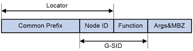
An SRv6 SID is in the format of IPv6 address, but the IPv6 address does not belong to any interface on any device.
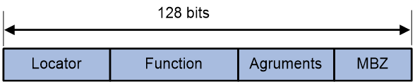
As shown in Figure 1, an SRv6 SID contains the Locator, Function, Arguments, and Must be zero (MBZ) portions.
· Locator—Identifies the network segment of the SID. The locator of an SRv6 SID must be unique in the SR domain.
· Function—Contains an opcode that identifies the network function of an SID. An SR node will execute the function in the SRv6 SID Function field of an SRv6 packet after it receives that SRv6 packet.
· Arguments—Defines flow and service parameters for SRv6 packets.
· MBZ—When the total number of bits in the Locator, Function, and Arguments portions is less than 128 bits, the remaining bits are padded with 0s.
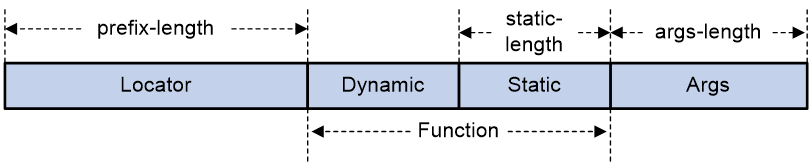
According to whether SRv6 SIDs are compressible, SRv6 SIDs are divided into the following categories for a locator:
· Non-compressible SRv6 SIDs—Include static and dynamic SRv6 SIDs. The formats are as follows:
¡ Static SRv6 SID = ipv6-prefix + 0s + opcode + 0s.
- The ipv6-prefix portion is specified by using the ipv6-address and prefix-length arguments in the locator command. The number of bits occupied by the ipv6-prefix portion is determined by the prefix-length argument.
- The number of bits occupied by 0s (following the ipv6-prefix portion) is 128 - prefix-length - static-length - args-length.
- opcode represents the static portion in the Function field. The number of bits occupied by the opcode is the value of the static-length argument.
- The number of bits occupied by 0s (following the opcode portion) is the value of the args-length argument..
¡ Dynamic SRv6 SID = ipv6-prefix + dynamic + static + 0s.
- The ipv6-prefix portion is specified by using the ipv6-address and prefix-length arguments in the locator command. The number of bits occupied by the ipv6-prefix portion is determined by the prefix-length argument.
- dynamic represents the dynamic portion in the Function field. The value for this portion cannot be all zeros. The number of bits occupied by this portion is 128 - prefix-length - static-length - args-length.
- static represents the static portion in the Function field. The number of bits occupied by this portion is static-length. This portion can use any value.
- The number of bits occupied by 0s is the value of the args-length argument.
For example, use the locator test1 ipv6-prefix 100:200:DB8:ABCD:: 64 static 24 args 32 command.
¡ The locator is 100:200:DB8:ABCD::. The length is 64 bits.
¡ The static portion length is 24 bits.
¡ The Args portion length is 32 bits.
¡ The dynamic portion length is 8 bits.
In this example, the following non-compressible static SRv6 SID range and dynamic SRv6 SID range are obtained on the locator:
¡ The start value for static SRv6 SIDs is 100:200:DB8:ABCD:0:1::.
¡ The end value for static SRv6 SIDs is 100:200:DB8:ABCD:FF:FFFF::.
¡ The start value for dynamic SRv6 SIDs is 100:200:DB8:ABCD:100::.
¡ The end value for dynamic SRv6 SIDs is 100:200:DB8:ABCD:FFFF:FFFF::.
Figure 2 Non-compressible SRv6 SIDs
· Compressible SRv6 SIDs—You can specify compressible SRv6 SIDs in a static segment or use IGP to automatically allocate compressible SRv6 SIDs in a dynamic segment. For example, use the locator test1 ipv6-prefix 100:200:DB8:ABCD:: 64 common-prefix 48 coc32 static 8 args 16 command.
¡ The locator is 100:200:DB8:ABCD::. The length is 64 bits.
¡ The common prefix length is 48 bits. A compressed SRv6 SID does not contain this portion.
¡ The static portion length is 8 bits.
¡ The Args portion length is 16 bits.
¡ The dynamic portion length is 8 bits.
In this example, the following compressible static SRv6 SID range and dynamic SRv6 SID range are obtained on the locator:
¡ The start value for static SRv6 SIDs is 100:200:DB8:ABCD:1::.
¡ The end value for static SRv6 SIDs is 100:200:DB8:ABCD:FF::.
¡ The start value for dynamic SRv6 SIDs is 100:200:DB8:ABCD:100::.
¡ The end value for dynamic SRv6 SIDs is 100:200:DB8:ABCD:FFFF::.
Figure 3 Compressible SRv6 SIDs
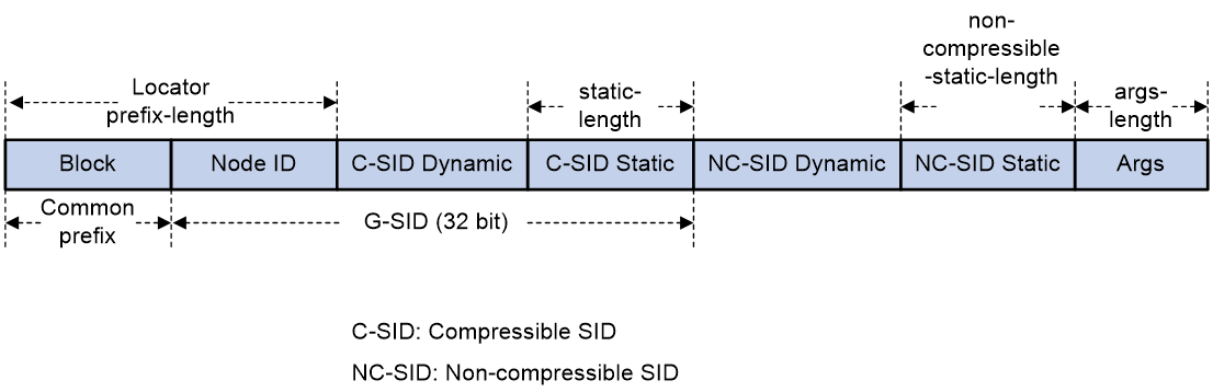
· Compressible and non-compressible hybrid SRv6 SIDs—A locator supports the combination of the following SRv6 SIDs:
¡ Compressible static SRv6 SIDs.
¡ Compressible dynamic SRv6 SIDs.
¡ Non-compressible static SRv6 SIDs.
¡ Non-compressible dynamic SRv6 SIDs.
For example, use the locator test1 ipv6-prefix 100:200:DB8:ABCD:: 64 common-prefix 48 coc-both non-compress-static 16 static 8 args 16 command.
¡ The locator is 100:200:DB8:ABCD::. The length is 64 bits.
¡ The common prefix length is 48 bits. A compressed SRv6 SID does not contain this portion.
¡ The compressible static portion length is 8 bits.
¡ The compressible dynamic portion length is 8 bits. This value is calculated by using the following formula: 32 – (prefix-length – common-prefix-length) – compressible-static-length.
¡ The non-compressible static portion length is 16 bits.
¡ The non-compressible dynamic portion length is 16 bits. This value is calculated by using the following formula: 128 – common-prefix-length – args-length – 32 – non-compressible-static-length.
¡ The Args portion length is 16 bits.
In this example, the following compressible static SRv6 SID range and dynamic SRv6 SID range are obtained on the locator:
¡ The start value for compressible static SRv6 SIDs is 100:200:DB8:ABCD:1::.
¡ The end value for compressible static SRv6 SIDs is 100:200:DB8:ABCD:FF::.
¡ The start value for compressible dynamic SRv6 SIDs is 100:200:DB8:ABCD:100::.
¡ The end value for compressible dynamic SRv6 SIDs is 100:200:DB8:ABCD:FFFF::.
The following non-compressible static SRv6 SID range and dynamic SRv6 SID range are obtained on the locator:
¡ The start value for non-compressible static SRv6 SIDs is 100:200:DB8:ABCD::1:0.
¡ The end value for non-compressible static SRv6 SIDs is 100:200:DB8:ABCD::FFFF:0.
¡ The start value for non-compressible dynamic SRv6 SIDs is 100:200:DB8:ABCD:0:1::.
¡ The end value for non-compressible dynamic SRv6 SIDs is 100:200:DB8:ABCD:0:FFFF:FFFF:0.
Figure 4 Compressible and non-compressible hybrid SRv6 SIDs
According to the functions of SRv6 SIDs, SRv6 SIDs are divided into the following categories:
· End SID—Identifies the prefix of a destination address in the network.
· End.X SID—Identifies a link in the network.
· End.DT4 SID—Identifies an IPv4 VPN in the network. The function of an End.DT4 SID is decapsulating packets and searching the routing table of the corresponding IPv4 VPN instance to forward the packets. End.DT4 SIDs are applicable to IPv4 private network access scenarios.
· End.DT6 SID—Identifies an IPv6 VPN in the network. The function of an End.DT6 SID is decapsulating packets and searching the routing table of the corresponding IPv6 VPN instance to forward the packets. End.DT6 SIDs are applicable to IPv6 private network access scenarios.
· End.DT46 SID—Identifies an IPv4 or IPv6 VPN in the network. End.DT46 SIDs are applicable to IPv4 and IPv6 private network concurrent access scenarios.
· End.DX4 SID—Identifies an IPv4 next hop in the network. The function of an End.DX4 SID is decapsulating packets and forwarding the decapsulated IPv4 packets out of the Layer 3 interface bound to the SID to a specific next hop. End.DX4 SIDs are applicable to IPv4 private network access scenarios.
· End.DX6 SID—Identifies an IPv6 next hop in the network. The function of an End.DX6 SID is decapsulating packets and forwarding the decapsulated IPv6 packets out of the Layer 3 interface bound to the SID to a specific next hop. End.DX6 SIDs are applicable to IPv6 private network access scenarios.
· End.DX2 SID—Identifies one end of a Layer 2 cross-connect. The function of an End.DX2 SID is removing the outer IPv6 header and SRH of packets and forwarding the decapsulated packets to the output interface of the SID. End.DX2 SIDs are applicable to EVPN VPWS scenarios.
· End.DX2L SID—Identifies packets that come from a bypass SRv6 PW. The packets will not be forwarded back to the bypass SRv6 PW for loop prevention. The function of an End.DX2L SID is removing the outer IPv6 header and SRH of packets and forwarding the decapsulated packets to the output interface of the SID. End.DX2L SIDs are applicable to EVPN VPWS over SRv6 multihomed sites.
· End.DT2M SID—Identifies one end of a Layer 2 cross-connect and floods traffic. The function of an End.DT2M SID is removing the outer IPv6 header and SRH of packets and flooding the decapsulated packets in the VSI. End.DT2M SIDs are applicable to EVPN VPLS BUM traffic.
· End.DT2U SID—Identifies one end of a Layer 2 cross-connect and performs unicast forwarding. The function of an End.DT2U SID is removing the outer IPv6 header and SRH of packets, looking up the MAC address table for the destination MAC address, and forwarding the packets to the output interface based on the MAC address entry. End.DT2U SIDs are applicable to EVPN VPLS unicast traffic.
· End.DT2UL SID—Identifies packets that come from a bypass SRv6 PW. The packets will not be forwarded back to the bypass SRv6 PW for loop prevention. The function of an End.DT2UL SID is removing the outer IPv6 header and SRH of packets and forwarding the packets to the output interface through destination MAC address lookup. End.DT2UL SIDs are applicable to EVPN VPLS over SRv6 multihomed sites.
· End.OP SID—Applies to the SRv6 OAM scenario. For more information about End.OP SIDs, see "Configuring SRv6 OAM."
· End.M SID—Applies to the SRv6 TE policy tailend protection scenario. For more information about End.M SIDs, see "Configuring SRv6 TE policies."
· End.T SID—Applies to the inter-AS option B solution. For more information about End.T SIDs, see "Configuring IP L3VPN over SRv6" and "Configuring EVPN L3VPN over SRv6."
Use IGP to advertise SRv6 SIDs for an SR node. The other SR nodes will generate route entries of that SR node based on the advertised information.
SRv6 SID flavors
Use SRv6 SID flavors to change the forwarding behaviors of SRv6 SIDs in order to meet multiple service requirements. The following SRv6 SID flavors are supported:
· NO-FLAVOR—The SRv6 SID does not carry any flavors.
· Penultimate Segment POP of the SRH (PSP)—The penultimate SRv6 node removes the SRH to reduce the workload of the end SRv6 node and improve the forwarding efficiency. The end SRv6 node does not read the SRH, and it only looks up the local SID table for the destination IPv6 address of packets to forward the packets.
· NO PSP—The penultimate SRv6 node does not remove the SRH. For correct connectivity detection in the SRv6 OAM scenario, make sure the SRH is not removed on the penultimate SRv6 node. The device needs to obtain the SID from the SRH to identify the link connectivity. (This flavor type is not supported in the current software version.)
· Ultimate Segment POP of the SRH (USP)—The ultimate SRv6 node (endpoint node) removes the SRH from the packets. In an SRv6 VPN network, upon obtaining the forwarding action based on the SID, the PE removes the SRH from the packets and forwards the packets to the CE.
· Ultimate Segment Decapsulation (USD)—The ultimate SRv6 node (endpoint node) removes the outer IPv6 header from the packets. In the TI-LFA scenario, the endpoint node in the repair list removes the outer IPv6 header from the packets and forwards the decapsulated packets to the destination node.
· Continue of Compression (COC)—The SID next to the current SID is a G-SID. A G-SID is used in a compression scenario to reduce the length of SRH.
The device supports advertising SRv6 SIDs with the following flavor types through IGP or BGP:
· NO-FLAVOR
· PSP
· PSP&USP&USD
· COC
Local SID forwarding table
An SRv6-enabled node maintains a local SID forwarding table that records the SRv6 SIDs generated on the local node. The local SID forwarding table has the following functions:
· Stores local generated SRv6 SID forwarding information.
· Stores SRv6 SID operation types.
Segment List
A Segment List is an ordered list of SIDs, which is also referred to as a Segment Identifier (SID) list in this document. The SR nodes forward packets based on the SIDs in the order that they are arranged in the SID list.
SRv6 tunnel
An SRv6 tunnel is a virtual point-to-point connection established between the SRv6 ingress node and egress node. IPv6 packets are encapsulated at the ingress node and de-encapsulated at the egress node.
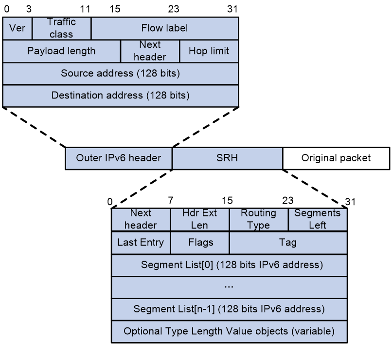
SRv6 packet format
An outer IPv6 header and a Segment Routing Header (SRH) are added to the original Layer 3 data packet to form an SRv6 packet.
As shown in Figure 5, the value for the Next Header field is 43 in the outer IPv6 header, which indicates that the header next to the IPv6 header is a routing extension header. The value for the Routing Type field in the routing extension header is 4, which indicates that the routing extension header is an SRH. The SRH header contains the following fields:
· 8-bit Next Header—Identifies the type of the header next to the SRH.
· 8-bit Hdr Ext Len—Length of the SRH header in 8-octet units, not including the first 8 octets.
· 8-bit Routing Type—The value for this field is 4, which represents SRH.
· 8-bit Segments Left—Contains the index of the next segment to inspect in the Segment List. The Segments Left field is set to n-1 where n is the number of segments in the Segment List. Segments Left is decremented at each segment.
· 8-bit Last Entry—Contains the index of the first SID in the path used to forward the packet.
· 8-bit Flags—Contains flags.
· 16-bit Tag—Tags a packet as part of a class or group of packets, for example, packets sharing the same set of properties.
· Segment List—Contains 128-bit IPv6 addresses representing the ordered segments. The Segment List is encoded starting from the last segment of the path. The first element of the segment list (Segment List [0]) contains the last segment of the path, the second element (Segment List [1]) contains the penultimate segment of the path and so on. The number enclosed in a pair of brackets is the index of a segment.
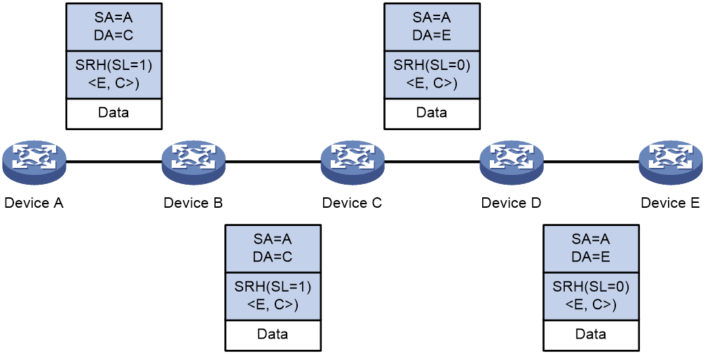
SRv6 packet forwarding
As shown in Figure 6, a source node receives a packet that matches an SRv6 path. Device A is the source node, Device C and Device E are endpoint nodes, and Device B and Device D are transit nodes. The packet is forwarded through the SRv6 path as follows:
1. Upon receiving an IPv6 packet, Device A performs the following operations:
a. Encapsulates an SRH to the packet. The packet must pass two segments to reach Device E, so the Segments Left (SL) in the SRH is set to 1 (the number of segments along the path minus 1). The Segment List contains Segment List [0]=E and Segment List [1]=C.
b. Encapsulates an outer IPv6 header to the packet. The source address of the IPv6 header is an IP address on Device A and the destination address is determined by the SL value. On Device A, the SL value is 1, which points to the SID on Device C, so the destination address is the SID on Device C.
c. Looks up the routing table based on the destination address of the outer IPv6 header and forwards the packet to Device B.
2. Device B looks up the routing table based on the destination address of the outer IPv6 header and forwards the packet to Device C.
3. Device C performs the following operations:
a. Checks the SL value in the SRH and decreases the value by 1 if the SL value is greater than 0.
b. Updates the destination address to the address pointed by the SL. In this example, the SL is 0, which points to the SID on Device E. Device C replaces the destination address in the outer IPv6 header with the SID on Device E.
c. Looks up the routing table based on the destination address of the outer IPv6 header and forwards the packet to Device D.
4. Device D looks up the routing table based on the destination address of the outer IPv6 header and forwards the packet to Device E.
5. Device E checks the SL value in the SRH and finds that the value has decreased to 0. The device performs the following operations:
a. Decapsulates the packet by removing the outer IPv6 header and the SRH.
b. Forwards the original packet to the destination based on the destination address.
Figure 6 SRv6 packet forwarding
Directing traffic to an SRv6 tunnel
After an SRv6 tunnel is established, traffic is not forwarded on the tunnel automatically. You must direct the traffic to the tunnel by configuring a static route or automatic route advertisement.
Static routing
You can direct traffic to an SRv6 tunnel by creating a static route that reaches the destination through the tunnel interface on the source node. This is the easiest way to implement SRv6 tunnel forwarding. When traffic to multiple networks is to be forwarded through the SRv6 tunnel, you must configure multiple static routes, resulting in increased configuration and maintenance workloads.
For more information about static routing, see Layer 3—IP Routing Configuration Guide.
Automatic route advertisement
Automatic route advertisement distributes the SRv6 tunnel to the IGP (OSPF or IS-IS), so the SRv6 tunnel can participate in IGP route calculation. Automatic route advertisement is easy to configure and maintain.
Automatic route advertisement can be implemented by using the following methods:
· IGP shortcut—Also known as AutoRoute Announce. It considers the SRv6 tunnel as a link that directly connects the tunnel ingress node and the egress node. Only the ingress node uses the SRv6 tunnel during IGP route calculation.
· Forwarding adjacency—Considers the SRv6 tunnel as a link that directly connects the tunnel ingress node and the egress node, and advertises the link to the network through an IGP. Every node in the network uses the SRv6 tunnel during IGP route calculation.
|
|
IMPORTANT: Only IGP shortcut is supported in the current software version. |
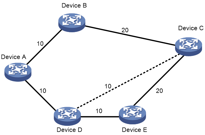
As shown in Figure 7, an SRv6 tunnel exists from Device D to Device C. IGP shortcut enables only the ingress node Device D to use the SRv6 tunnel in IGP route calculation. Device A cannot use this tunnel to reach Device C. With forwarding adjacency enabled, Device A can learn this SRv6 tunnel and transfer traffic to Device C by forwarding the traffic to Device D.
Figure 7 IGP shortcut and forwarding adjacency diagram
G-SRv6
Background
In an SRv6 TE policy scenario, the administrator needs to add the 128-bit SRv6 SIDs of SRv6 nodes on the packet forwarding path into the SID list of the SRv6 TE policy. If the packet forwarding path is long, a large number of SRv6 SIDs will be added to the SID list of the SRv6 TE policy. This greatly increases the size of the SRv6 packet header, resulting in low device forwarding efficiency and reduced chip processing speed. The situation might be worse in a scenario that spans across multiple ASs where a much greater number of end-to-end SRv6 SIDs exist.
Generalized SRv6 (G-SRv6) encapsulates shorter SRv6 SIDs (G-SIDs) in the segment list of SRH by compressing the 128-bit SRv6 SIDs. This reduces the size of the SRv6 packet header and improves the efficiency for forwarding SRv6 packets. In addition, G-SRv6 supports both 128-bit SRv6 SIDs and G-SIDs in a segment list.
About G-SRv6
Typically, an address space is reserved for SRv6 SID allocation in an SRv6 subnet. This address space is called an SID space. In the SRv6 subnet, all SIDs are allocated from the SID space. The SIDs have the same prefix (common prefix). The SID common prefix is redundant information in the SRH.
G-SRv6 removes the common prefix and carries only the variable portion of SRv6 SIDs (G-SIDs) in the segment list, effectively reducing the SRv6 packet header size. To forward a packet according to routing table lookup, SRv6 replaces the destination IP address of the packet with the combination of the G-SID and common prefix in the segment list of the SRH.
With the compression efficiency and network scale taken into consideration, the ideal length of SRv6 SIDs is 32 bits after compression through G-SRv6.
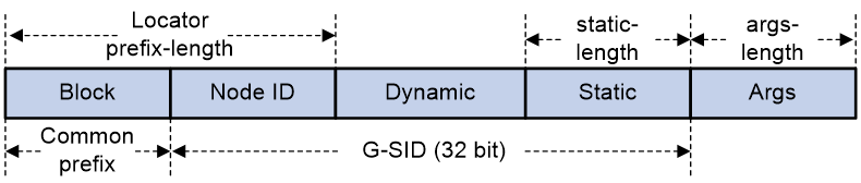
G-SID format
As shown in Figure 8, the locator portion of an SRv6 SID contains the Common Prefix and Node ID portions. The Common Prefix portion represents the address of the common prefix. The Node ID portion identifies a node. G-SRv6 can compress all SIDs with the same common prefix into 32-bit G-SIDs. A G-SID contains the Node ID and Function portions of a 128-bit SRv6 SID. A 128-bit SRv6 SID is formed by the Common Prefix portion, a 32-bit G-SID, and the 0 (Args&MBZ) portion.
Figure 8 Compressible SRv6 SID
G-SRv6 packet
G-SRv6 packet format
As shown in Figure 9, G-SRv6 can encapsulate both G-SIDs and 128-bit SRv6 SIDs in the segment list of the SRH. It needs to encapsulate four G-SIDs in a group to the original location of a 128-bit SRv6 SID. If the location contains fewer than four G-SIDs (less than 128 bits), G-SRv6 pads the remaining bits with 0s. Multiple consecutive G-SIDs form a compressed path, called a G-SID list. A G-SID list can contain one or more groups of G-SIDs.
|
|
NOTE: If the SRv6 SID of the next node requires compression, the routing protocol adds the Continue of Compression (COC) flag to the advertised SRv6 SID of the local node. The COC flag indicates that the next SRv6 SID is a G-SID. A COC flag only identifies the forwarding behavior of an SRv6 SID, and is not actually carried in the packet. The COC flags in Figure 9 are for illustration purposes only. |
The G-SIDs in the segment list are arranged as follows:
· The SRv6 SID before the G-SID list is a 128-bit SRv6 SID with the COC flag, indicating that the next SID is a 32-bit G-SID.
· Except the last G-SID, all G-SIDs in the G-SID list must carry the COC flag to indicate that the next SID is a 32-bit G-SID.
· The last G-SID in the G-SID list must be a 32-bit G-SID without the COC flag, indicating that the next SID is a 128-bit SRv6 SID.
· The next SRv6 SID after the G-SID list is a 128-bit SRv6 SID that can carry the COC flag or does not carry the COC flag.
Calculating the destination address with G-SID
As shown in Figure 10, G-SRv6 combines the G-SID and Common Prefix in the segment list to form a new destination address.
· Common Prefix—Common prefix address manually configured by the administrator.
· G-SID—Compressed 32-bit SID obtained from the SRH.
· SID Index (SI)—Index that identifies a G-SID in a group of G-SIDs. This field is the least significant two bits of the destination IPv6 address. The value range is 0 to 3. The SI value decreases by 1 at each node that performs SID compression. If the SI value becomes 0, the SL value decreases by 1. In a group of G-SIDs in the segment list, the G-SIDs are arranged from left to right based on SI values. The SI value is 0 for the leftmost G-SID, and is 3 for the rightmost G-SID.
· 0—If the total length of the Common Prefix, G-SID, and SI portions is less than 128 bits, the deficient bits are padded with 0s before the SI portion.
Figure 10 Destination address calculated with G-SID
Suppose the following conditions exist:
· The Common Prefix deployed on the SRv6 node is A:0:0:0::/64.
· The G-SID in the SRv6 packet is 1:1.
· The SI value associated with the G-SID is 3.
Based on the previous conditions, the device calculates the destination address as A:0:0:0:1:1::3.
Upon receiving the G-SRv6 packet, the SRv6 node calculates the destination address for the packet as follows:
· If the destination address of the packet is a 128-bit SRv6 SID with the COC flag in the segment list, the next SID is a G-SID. The device decreases the SI value by 1 and searches for the G-SID group corresponding to [SI-1]. Then, the device calculates the destination address based on the 32-bit G-SID identified by SI value 3.
· If the destination address of the packet is a 32-bit SRv6 SID with the COC flag in the segment list, the next SID is a G-SID.
¡ If the SI value is larger than 0, the device decreases the SI value by 1 and searches for the G-SID group corresponding to SL value of the packet. Then, the device calculates the destination address based on the 32-bit G-SID identified by [SI-1].
¡ If the SI value is equal to 0, the device decreases the SL value by 1, resets the SI value to 3, and searches for the G-SID group corresponding to the SL value of the packet. Then, the device calculates the destination address based on the 32-bit G-SID identified by SI value 3.
· If the destination address of the packet is a 32-bit SRv6 SID without the COC flag in the segment list, the device decreases the SL value by 1 and searches for the 128-bit SRv6 SID corresponding to [SL-1]. Then, the device replaces the destination address in the IPv6 header with the SRv6 SID.
· If the destination address of the packet is a 128-bit SRv6 SID without the COC flag in the segment list, the device decreases the SL value by 1 and searches for the 128-bit SRv6 SID corresponding to [SL-1]. Then, the device replaces the destination address in the IPv6 header with the SRv6 SID.
BGP-EPE
IGP for SRv6 cannot advertise SRv6 SIDs across ASs. To advertise SRv6 SIDs across ASs, use BGP Egress Peer Engineering (BGP-EPE).
BGP-EPE can allocate BGP peer SIDs to inter-AS segments.
· If the device has established BGP LS peer relationship with a network controller, it advertises the peer SIDs to the network controller through extended BGP LS messages. Then, the controller orchestrates the IGP SIDs and BGP peer SIDs to realize optimal inter-AS traffic forwarding.
· If the device has not established BGP LS peer relationship with a network controller, it advertises the peer SIDs to a BGP peer through BGP LS messages. When a device that has established BGP LS peer relationship with a network controller receives the peer SIDs, it advertises the peer SIDs to the network controller through BGP LS messages.
BGP-EPE supports automatic peer SID allocation and static peer SID allocation. As shown in Figure 11, BGP-EPE can allocate the following peer SIDs:
· PeerNode SID—Identifies a peer node. BGP-EPE allocates a PeerNode SID to each BGP session. If the device establishes EBGP peer relationship with a peer through a loopback interface, it might have multiple physical links to reach the peer. In this case, the PeerNode SID for this peer is associated with multiple output interfaces. Traffic destined for this peer based on the PeerNode SID will be distributed among these output interfaces.
· PeerAdj SID—Identifies an adjacency link that can reach a peer node. If the device establishes EBGP peer relationship with a peer through a loopback interface, it might have multiple physical links to reach the peer. Each link is allocated a PeerAdj SID. When the device forwards traffic based on a PeerAdj SID, the traffic is forwarded out of the interface that is attached to the link identified by the PeerAdj SID.
· PeerNode-Adj SID—Identifies a peer node and identifies one or multiple adjacency links that can reach a peer node.
· PeerSet SID—Identifies a group of peer nodes in a BGP-EPE SRv6 peer set. A PeerSet SID corresponds to multiple PeerNode SIDs and PeerAdj SIDs. When the device forwards traffic based on a PeerSet SID, it distributes the traffic among multiple peers.
Figure 11 BGP-EPE network diagram
As shown in Figure 11, BGP-EPE allocates peer SIDs as follows:
· ASBR 1 and ASBR 3 have two direct physical links. They establish EBGP peer relationship through loopback interfaces. On ASBR 1, BGP-EPE allocates PeerNode SID 100:AB::1 to ASBR 3 and allocates PeerAdj SIDs 100:AB:1::2 and 100:AB:1::3 to the physical links. When ASBR 1 forwards traffic to ASBR 3 based on the PeerNode SID, the two physical links load share the traffic.
· EBGP peer relationship has been established between ASBR 1 and ASBR 5, between ASBR 2 and ASBR 4, and between ASBR 2 and ASBR 5 through directly connected physical interfaces. On ASBR 1, BGP-EPE allocates PeerNode SID 100:AB::2 to ASBR 5. On ASBR 2, BGP-EPE allocates PeerNode SIDs 100:AB::4 and 100:AB::5 to ASBR 4 and ASBR 5, respectively.
· ASBR 4 and ASBR 5 each has established EBGP peer relationship with ASBR 2. On ASBR 2, peers ASBR 4 and ASBR 5 are added to a peer set. BGP-EPE allocates PeerSet SID 100:AB::3 to the peer set. When ASBR 2 forwards traffic based on the PeerSet SID, the traffic is distributed to both ASBR 4 and ASBR 5 for load sharing.
The SIDs allocated to peers by BGP-EPE are not advertised to the peers. Route types used by the peers do not affect BGP-EPE.
TI-LFA FRR
Topology-Independent Loop-Free Alternate Fast Re-Route (TI-LFA FRR) provides link and node protection for SRv6 tunnels. When a link or node fails, TI-LFA FRR switches the traffic to the backup path to ensure continuous data forwarding.
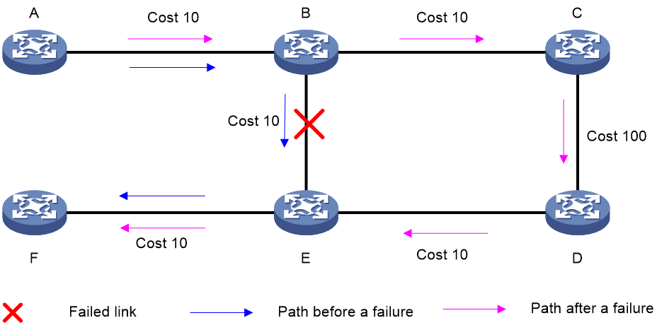
TI-LFA FRR background
As shown in Figure 12, node A sends data packets to node F. When the link between node B and node E fails, node B forwards the data packets to node C. The cost of the link between node C and node D is 100 (which is greater than the cost of the link between node C and node D) and the routes on node C have not converged. As a result, node C determines that the next hop of the optimal path to reach node F is node B. Then, node C forwards the data packets back to node B, which causes a loop.
Figure 12 TI-LFA application scenario
To resolve this issue, deploy TI-FLA on the SRv6 network. As shown in Figure 13, when the link between node B and node E fails, node B uses the backup path calculated by TI-LFA to forward the data packets along the B->C->D->E path.
Figure 13 TI-LFA forwarding network diagram
TI-LFA FRR concepts
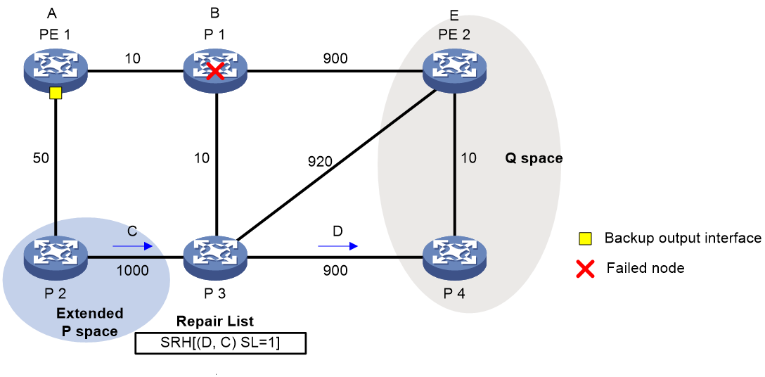
· P space—Use the source node of the protected link as the root to establish a shortest path tree. All nodes that are reachable from the source node without passing the protected link form the P space. Nodes in the P space are called P nodes.
· Extended P space—Use the source node of the protected link and its neighbors as the roots to establish shortest path trees. All nodes that are reachable from the source node or one of its neighbors without passing the protected link form the extended P space. The P space is a subset of the extended P space.
· Q space—Use the destination node of the protected link as the root to establish a reverse shortest path tree. All nodes that are reachable from the root node without passing the protected link form the Q space. Nodes in the Q space are called Q nodes.
· Repair list—A constraint path used to indicate how a P node reaches a Q node when the P space and Q space do not have common nodes. The repair list contains the following SRv6 SIDs:
¡ SRv6 SIDs of P nodes.
¡ SRv6 SIDs from P nodes to nearest Q nodes.
TI-LFA FRR path calculation
As shown in Figure 14, PE 1 is the source node. P 1 is the faulty node. PE 2 is the destination node. The numbers on links represent the link costs. A data flow traverses PE 1, P 1, and PE 2. To protect data against P 1 failure, TI-LFA FRR calculates the extended P space, Q space, shortest path tree converged after P 1 fails, repair list, and backup output interface, and creates the backup forwarding entry.
TI-LFA FRR calculates the backup path by using the following steps:
1. Calculates the extended P space: P 2.
2. Calculates the Q space: PE 2 and P 4.
3. Calculates the shortest path tree converged after P 1 fails: PE 1 --> P 2 --> P 4 --> PE 2.
4. Calculates the repair list: End.X SID C of the link between P 2 and P 3 and End.X SID D of the link between P 3 and P 4.
5. Calculates the backup output interface, that is, the output interface to the next hop after the link from PE 1 to P 1 fails.
TI-LFA FRR forwarding process
After TI-LFA FRR finishes backup path calculation, traffic will be switched to the backup path in response to a primary path failure.
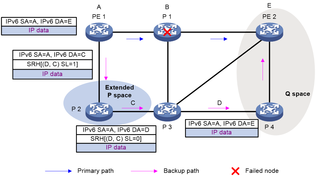
As shown in Figure 15, P 2 is a P node and P 4 and PE 2 are Q nodes. When the next hop on the primary path (P 1) fails, TI-LFA FRR switches the traffic to the backup path. The following are the detailed steps:
1. PE 1 looks up the IPv6 routing table for the destination IPv6 address of a packet and finds that the next hop is P 2. PE 1 encapsulates the packet according to the repair list.
¡ Adds an SRH header. The SID list is Segment List [0]=D and Segment List [1]=C. The SIDs are arranged from the farthest node to the nearest node.
¡ Adds an outer IPv6 header. The source address is address A on source node PE 1 and the destination address is the address pointed by SL. Because the SL is 1, the destination address is C as pointed by Segment List [1].
2. After P2 receives the packet, it performs the following operations:
a. Checks the SL value in the SRH header and decreases the value by 1.
b. Searches for the address pointed by Segment List [0] and finds that the address is End.X SID D between P 3 and P 4.
c. Replaces the destination address in the outer IPv6 header with End.X SID D.
d. Obtains the output interface and next hop according to End.X SID C and forwards the encapsulated packet to P 3.
3. After P3 receives the packet, it performs the following operations:
a. Checks the SL value in the SRH header and finds that the SL value is 0.
b. Decapsulates the packet.
c. Obtains the output interface and next hop according to End.X SID D and forwards the packet to P 4.
4. After P4 receives the packet, it searches the IP routing table for the destination IP address of the packet and forwards the packet to PE 2.
Figure 15 Data forwarding over the TI-LFA FRR backup path
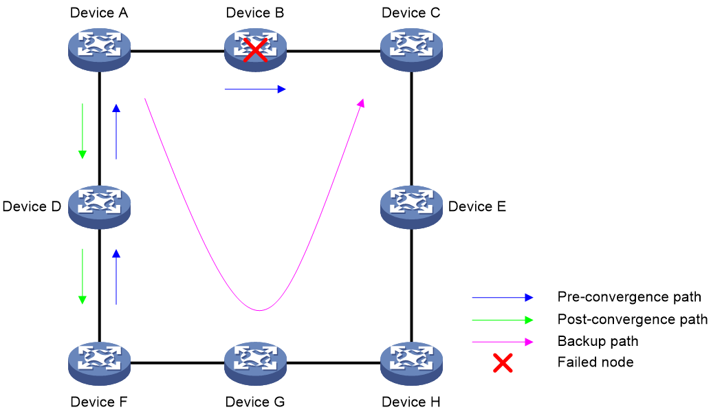
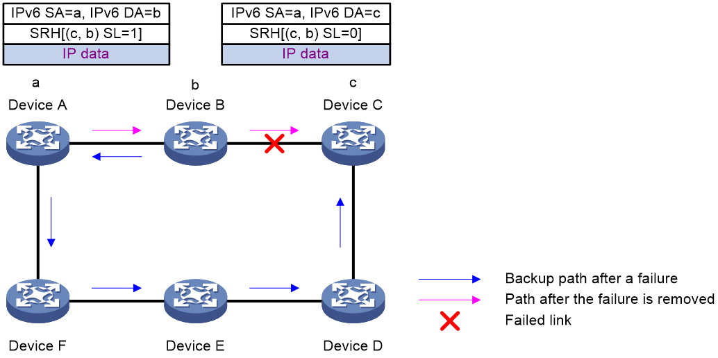
Microloop avoidance after a network failure
As shown in Figure 16, when Device B fails, traffic to Device C will be switched to the backup path calculated by TI-LFA. After Device A finishes route convergence, traffic will be switched to the post-convergence path. If Device D and Device F have not finished route convergence and still forward traffic along the pre-convergence path, a loop is formed between Device A and Device F. The loop exists until Device D and Device F finish route convergence.
FRR microloop avoidance and SR microloop avoidance can resolve this issue. After you configure TI-LFA, Device A first switches traffic to the backup path calculated by TI-LFA when Device B fails. Then, Device A waits for Device D and Device F to finish route convergence before starting route convergence. After Device A also finishes route convergence, Device A switches the traffic to the converged route.
Figure 16 Diagram for microloop avoidance after a network failure
SR microloop avoidance after a failure recovery
As shown in Figure 17, before the link between Device B and Device C recovers, traffic traverses along the backup path. After the link recovers, Device A forwards the traffic to Device B if Device A finishes route convergence before Device B. With route convergence unfinished, Device B still forwards the traffic along the backup path. A loop is formed between Device A and Device B.
SR microloop avoidance can resolve this issue. After the link recovers, SR microloop avoidance automatically calculates the optimal path from Device A to Device C and forwards traffic along the path. To forward a packet along the newly calculated path, Device A adds, for example, the adjacency SID from Device B to Device C, to the packet and then sends the packet to Device B. Then, Device B forwards the packet to Device C based on the path information.
Upon expiration of the microloop avoidance RIB-update-delay timer and completion of route convergence on Device B, Device A does not add path information to packets anymore. It will forward packets to Device C as usual.
Figure 17 Diagram for SR microloop avoidance after a failure recovery
Protocols and standards
· draft-previdi-6man-segment-routing-header
· draft-ietf-6man-segment-routing-header
· draft-filsfils-spring-segment-routing
· draft-filsfils-spring-srv6-network-programming
Restrictions and guidelines: SRv6 configuration
In standard system operating mode, this feature is available only for the following cards:
|
Card category |
Cards |
|
CEPC |
CEPC-CQ8L, CEPC-CQ8LA, CEPC-CQ8L1A, CEPC-CQ16L1 |
|
CSPEX |
CSPEX-1802X, CSPEX-1802XA, CSPEX-2612XA, CSPEX-1812X-E, CSPEX-2304X-G, CSPEX-1502XA |
|
SPE |
RX-SPE200-E |
In SDN-WAN system operating mode, this feature is available only for the following cards:
|
Card category |
Cards |
|
CEPC |
CEPC-XP4LX, CEPC-XP24LX, CEPC-XP48RX, CEPC-CP4RX, CEPC-CP4RXA, CEPC-CP4RX-L, CEPC-CQ8L, CEPC-CQ8LA, CEPC-CQ8L1A, CEPC-CQ16L1 |
|
CSPEX |
CSPEX-1304X, CSPEX-1404X, CSPEX-1502X, CSPEX-1504X, CSPEX-1504XA, CSPEX-1602X, CSPEX-1602XA, CSPEX-1804X, CSPEX-1512X, CSPEX-1612X, CSPEX-1812X, CSPEX-1802X, CSPEX-1802XA, CSPEX-2612XA, CSPEX-1812X-E, CSPEX-2304X-G, CSPEX-1502XA |
|
SPE |
RX-SPE200, RX-SPE200-E |
|
OAA |
IM-NGFWX-IV |
SRv6 tasks at a glance
To configure SRv6, perform the following tasks:
1. Configuring SRv6 SIDs
¡ Configuring non-compressible SRv6 SIDs
This task is required if SRv6 compression is enabled.
¡ Configuring compressible and non-compressible hybrid SRv6 SIDs
2. (Optional.) Manage SRv6 SIDs
¡ Configuring dynamic End.X SID deletion delay
¡ Configuring dynamic SID deletion delay
¡ Configuring the delay time to flush static End.X SIDs to the FIB
3. Using IGP to advertise SRv6 SIDs
4. Enabling BGP to advertise routes for a locator
This task is required in an inter-AS network.
6. (Optional.) Configuring the SRv6 MTU
7. (Optional.) Configuring the SRv6 DiffServ mode
8. (Optional.) Enabling SNMP notifications for SRv6
Prerequisites for SRv6
Before you configure an SRv6 tunnel, perform the following tasks:
· Determine the ingress node, transit nodes, and egress node of the SRv6 tunnel.
· Plan the IPv6 address of each SR node.
Configuring non-compressible SRv6 SIDs
Configuring the local locator and opcode
Restrictions and guidelines
Each locator must have a unique name.
Do not configure the same IPv6 address prefix and prefix length for different locators. In addition, the IPv6 address prefixes of different locators cannot overlap.
You cannot disable SRv6 or delete a locator in SRv6 view if the locator has dynamic SRv6 SIDs that are being used.
You can change a COC-both locator to a common locator or vice versa without deleting the configured locator but directly editing the command parameters, as follows:
· Change a common locator to a COC-both locator by adding the common-prefix and non-compress-static parameters. Other parameters cannot be edited.
For example, assume you configure a common locator as locator test ipv6-prefix 100:1:: 80 static 8 args 8. You can change the locator to a COC-both locator by executing locator test ipv6-prefix 100:1:: 80 common-prefix 64 coc-both non-compress-static 8 static 8 args 8.
· Change a COC-both locator to a common locator by deleting the common-prefix and non-compress-static parameters. Other parameters cannot be edited.
For example, assume you configure a COC-both locator as locator test ipv6-prefix 100:1:: 80 common-prefix 64 coc-both non-compress-static 8 static 8 args 8. You can change the locator to a common locator by executing locator test ipv6-prefix 100:1:: 80 static 8 args 8.
Procedure
1. Enter system view.
system-view
2. Enable SRv6 and enter SRv6 view.
segment-routing ipv6
3. Configure a locator and enter SRv6 locator view.
locator locator-name [ ipv6-prefix ipv6-address prefix-length [ args args-length | static static-length ] * ]
4. (Optional.) Enable anycast for the locator.
anycast enable
By default, anycast is disabled for a locator.
A locator is an anycast locator if the A-bit is set in the Flags field of the Locator TLV in routing protocol packets. An anycast locator is shared by a group of SRv6 nodes.
5. Configure an opcode. Perform one of the following tasks:
¡ Configure an opcode for End SIDs.
opcode { opcode | hex hex-opcode } end { no-flavor | psp | psp-usp-usd }
¡ Configure an opcode for End.X SIDs.
opcode { opcode | hex hex-opcode } end-x interface interface-type interface-number [ member-port interface-type interface-number ] nexthop nexthop-ipv6-address { no-flavor | psp | psp-usp-usd }
¡ Configure an opcode for End.DT4 SIDs.
opcode { opcode | hex hex-opcode } end-dt4 [ vpn-instance vpn-instance-name [ evpn | l3vpn-evpn ] ]
The specified VPN instance must exist. The same End.DT4 SID cannot be configured in different VPN instances.
¡ Configure an opcode for End.DT6 SIDs.
opcode { opcode | hex hex-opcode } end-dt6 [ vpn-instance vpn-instance-name [ evpn | l3vpn-evpn ] ]
The specified VPN instance must exist. The same End.DT6 SID cannot be configured in different VPN instances.
¡ Configure an opcode for End.DT46 SIDs.
opcode { opcode | hex hex-opcode } end-dt46 [ vpn-instance vpn-instance-name [ evpn | l3vpn-evpn ] ]
The specified VPN instance must exist. The same End.DT46 SID cannot be configured in different VPN instances.
¡ Configure an opcode for End.DX4 SIDs.
opcode { opcode | hex hex-opcode } end-dx4 interface interface-type interface-number nexthop nexthop-ipv4-address [ vpn-instance vpn-instance-name [ evpn ] ]
The specified VPN instance must exist. The same End.DX4 SID cannot be configured with different output interfaces or next hops.
¡ Configure an opcode for End.DX6 SIDs.
opcode { opcode | hex hex-opcode } end-dx6 interface interface-type interface-number nexthop nexthop-ipv6-address [ vpn-instance vpn-instance-name [ evpn ] ]
The specified VPN instance must exist. The same End.DX6 SID cannot be configured with different output interfaces or next hops.
¡ Configure an opcode for End.DX2 SIDs.
opcode { opcode | hex hex-opcode } end-dx2 xconnect-group group-name connection connection-name
The specified cross-connect group and cross-connect must exist.
opcode { opcode | hex hex-opcode } end-dx2 vsi vsi-name interface interface-type interface-number service-instance instance-id
The specified VSI must exist.
¡ Configure an opcode for End.DX2L SIDs.
opcode { opcode | hex hex-opcode } end-dx2l xconnect-group group-name connection connection-name
The specified cross-connect group and cross-connect must exist.
opcode { opcode | hex hex-opcode } end-dx2l vsi vsi-name interface interface-type interface-number service-instance instance-id
The specified VSI must exist.
¡ Configure an opcode for End.DT2M SIDs.
opcode { opcode | hex hex-opcode } end-dt2m vsi vsi-name
The specified VSI must exist. The same End.DT2M SID cannot be configured in different VSIs.
¡ Configure an opcode for End.DT2U SIDs.
opcode { opcode | hex hex-opcode } end-dt2u vsi vsi-name
The specified VSI must exist. The same End.DT2U SID cannot be configured in different VSIs.
¡ Configure an opcode for End.DT2UL SIDs.
opcode { opcode | hex hex-opcode } end-dt2ul vsi vsi-name
The specified VSI must exist. The same End.DT2UL SID cannot be configured in different VSIs.
¡ Configure an opcode for End.OP SIDs.
opcode { opcode | hex hex-opcode } end-op
¡ Configure an opcode for End.M SIDs.
opcode { opcode | hex hex-opcode } end-m mirror-locator ipv6-address prefix-length
Configuring the remote locator
About this task
In the EVPN VPWS over SRv6 scenario, if the PEs cannot use BGP routes to establish SRv6 PWs, you need to establish a static SRv6 PW between the PEs to ensure correct packet forwarding. Because the PEs cannot transmit SRv6 SID information through BGP routes, you need to configure the SRv6 SIDs assigned by the local and remote ends to the cross-connect. To configure the SRv6 SID assigned by the local end, configure the opcode command for the associated locator. To configure the SRv6 SID assigned by the remote end, create the remote locator, and then use the peer command to specify the remote locator in static SRv6 configuration view of the cross-connect.
The remote locator setting on the local PE must be the same as the locator setting on the remote PE. The local and remote PEs must use consistent locator, remote locator, and SRv6 SID settings. For example:
· Configuration on the local PE (PE 1):
locator pe1 ipv6-prefix 100:: 64 static 32
opcode 1 end.dx2 xconnect-group pe1 connection pe1
remote-locator pe2 ipv6-prefix 200:: 64 static 32
xconnect-group pe1
connection pe1
static-srv6 local-service-id 1 remote-service-id 2
peer 2::2 end-dx2-sid remote-locator pe2 opcode 1
· Configuration on the remote PE (PE 2):
locator pe2 ipv6-prefix 200:: 64 static 32
opcode 1 end.dx2 xconnect-group pe2 connection pe2
remote-locator pe1 ipv6-prefix 100:: 64 static 32
xconnect-group pe2
connection pe2
static-srv6 local-service-id 1 remote-service-id 2
peer 1::1 end-dx2-sid remote-locator pe1 opcode 1
The locator for the local PE is 100::/64, and the remote locator is 200::/6. The locator for the remote PE is 200::/64, and the remote locator is 100::/6. The SRv6 SID assigned by the local PE to the cross-connect is End.DX2 SID 100::1. The SRv6 SID assigned by the remote PE to the cross-connect is End.DX2 SID 200::1.
When deploying an SRv6 PW in the EVPN VPWS over SRv6 scenario for packet forwarding, make sure the destination IPv6 address for packets is the SRv6 SID of the remote locator. Upon receiving the packets, the remote PE searches the local locator SID forwarding table, and perform one of the following operations:
· If a matching SRv6 SID is found in the local locator, the remote PE forwards the packets based on the SRv6 SID.
· If no matching SRv6 SID is found in the local locator, the remote PE discards the packets.
Restrictions and guidelines
When you create a remote locator, you must specify an IPv6 address prefix, prefix length, and static length for the remote locator. When you enter the view of an existing remote SRv6 locator, you only need to specify the remote locator name.
Each remote locator must have a unique name.
Do not specify the same IPv6 address prefix for different remote locators. In addition, the IPv6 address prefixes of different remote locators cannot overlap.
Do not specify the same IPv6 address prefix for the remote locator and local locator. In addition, the IPv6 address prefixes of the remote locator and local locator cannot overlap.
Procedure
1. Enter system view.
system-view
2. Enable SRv6 and enter SRv6 view.
segment-routing ipv6
3. Configure a remote locator and enter remote SRv6 locator view.
remote-locator remote-locator-name [ ipv6-prefix ipv6-address prefix-length [ args args-length | static static-length ] * ]
Configuring G-SIDs
Restrictions and guidelines
The IPv6 prefix length must be longer than the common prefix length.
Procedure
1. Enter system view.
system-view
2. Enable SRv6 and enter SRv6 view.
segment-routing ipv6
3. Enable SRv6 compression.
srv6 compress enable
By default, SRv6 compression is disabled.
4. Configure a locator and enter SRv6 locator view.
locator locator-name [ ipv6-prefix ipv6-address prefix-length common-prefix common-prefix-length coc32 [ args args-length | static static-length ] * ]
5. Configure an opcode. Perform one of the following tasks:
¡ Configure an opcode for End SIDs.
opcode opcode end-coc32 { no-flavor | psp }
¡ Configure an opcode for End.X SIDs.
opcode opcode end-x-coc32 interface interface-type interface-number [ member-port interface-type interface-number ] nexthop nexthop-address { no-flavor | psp }
¡ Configure an opcode for other segments.
For more information, see "Configuring non-compressible SRv6 SIDs."
Configuring compressible and non-compressible hybrid SRv6 SIDs
Restrictions and guidelines
For a locator that has both compressible and non-compressible SRv6 SIDs, you can set the same opcode for compressible and non-compressible static SIDs.
You can change a COC-both locator to a common locator or vice versa without deleting the configured locator but directly editing the command parameters, as follows:
· Change a common locator to a COC-both locator by adding the common-prefix and non-compress-static parameters. Other parameters cannot be edited.
For example, assume you configure a common locator as locator test ipv6-prefix 100:1:: 80 static 8 args 8. You can change the locator to a COC-both locator by executing locator test ipv6-prefix 100:1:: 80 common-prefix 64 coc-both non-compress-static 8 static 8 args 8.
· Change a COC-both locator to a common locator by deleting the common-prefix and non-compress-static parameters. Other parameters cannot be edited.
For example, assume you configure a COC-both locator as locator test ipv6-prefix 100:1:: 80 common-prefix 64 coc-both non-compress-static 8 static 8 args 8. You can change the locator to a common locator by executing locator test ipv6-prefix 100:1:: 80 static 8 args 8.
Procedure
1. Enter system view.
system-view
2. Enable SRv6 and enter SRv6 view.
segment-routing ipv6
3. Enable SRv6 compression.
srv6 compress enable
By default, SRv6 compression is disabled.
4. Configure a locator and enter SRv6 locator view.
locator locator-name [ ipv6-prefix ipv6-address prefix-length common-prefix common-prefix-length coc-both [ non-compress-static non-compress-static-length ] [ args args-length | static static-length ] * ]
5. (Optional.) Reserve SRv6 SIDs.
reserved-sid-start sid-value count reserved-sid-count
By default, no SRv6 SIDs are reserved.
When the device generates an SRv6 TE policy based on received SRv6 TE policy routes, it must assign a BSID to the SRv6 TE policy. Use this command to reserve SRv6 SIDs that can be assigned to SRv6 TE policies as BSIDs. The reserved SRv6 SIDs cannot be used by other protocols.
6. Configure an opcode. Perform one of the following tasks:
¡ Configure an opcode for End (COCNONE) SIDs.
opcode { opcode | hex hex-opcode } end-coc-none { no-flavor | psp | psp-usp-usd }
End (COCNONE) SIDs are allocated from compressible SRv6 SID space. The SIDs have the same function as End SIDs.
¡ Configure an opcode for End.X (COCNONE) SIDs.
opcode { opcode | hex hex-opcode } end-x-coc-none interface interface-type interface-number [ member-port interface-type interface-number ] nexthop nexthop-ipv6-address { no-flavor | psp | psp-usp-usd }
End.X (COCNONE) SIDs are allocated from compressible SRv6 SID space. The SIDs have the same function as End.X SIDs.
¡ Configure an opcode for other segments.
For more information, see "Configuring non-compressible SRv6 SIDs."
Configuring dynamic End.X SID deletion delay
About this task
Packet loss occurs between OSPFv3 or IS-IS neighbors if the neighbors frequently delete and request dynamically allocated End.X SIDs for the links between them because of neighbor flapping. To resolve this issue, set a delay timer for deleting dynamically allocated End.X SIDs when the neighbors are disconnected. If the neighbors are still disconnected when the delay timer expires, the device deletes the dynamically allocated End.X SIDs.
Restrictions and guidelines
The device always immediately deletes automatically allocated End.X SIDs without any delay in the following situations:
· The reset ospfv3 process command is executed. For more information about this command, see OSPFv3 commands in Layer 3—IP Routing Command Reference.
· The reset isis all command is executed. For more information about this command, see IS-IS commands in Layer 3—IP Routing Command Reference.
· Interfaces are deleted or removed. For example, an interface module is removed, or a subinterface or VLAN interface is deleted.
Procedure
1. Enter system view.
system-view
2. Enter IS-IS IPv6 address family view or OSPFv3 process view.
¡ Execute the following commands in sequence to enter IS-IS IPv6 address family view:
isis [ process-id ] [ vpn-instance vpn-instance-name ]
address-family ipv6 [ unicast ]
¡ Enter OSPFv3 process view.
ospfv3 [ process-id | vpn-instance vpn-instance-name ] *
3. Enable dynamic End.X SID deletion delay and set the delay time.
segment-routing ipv6 end-x delete-delay [ time-value ]
By default, dynamic End.X SID deletion delay is enabled and the delay time is 1800 seconds.
Configuring dynamic SID deletion delay
About this task
To make sure BGP allocates the same SRv6 SID before and after a BGP session down-up event, perform this task to set a proper dynamic SID deletion delay. After the BGP session is down, the BGP-allocated SRv6 SID is not deleted within the delay time. If the BGP session becomes up within the delay time, the original SRv6 SID is used.
Restrictions and guidelines
If you delete the BGP configuration actively, the device immediately deletes the SRv6 SIDs dynamically allocated by BGP without a delay.
Procedure
1. Enter system view.
system-view
2. Enter BGP instance view.
bgp as-number [ instance instance-name ]
3. Configure the dynamic SID deletion delay time.
segment-routing ipv6 sid delete-delay [ time-value ]
By default, dynamic SID deletion delay time is 1800 seconds.
Configuring the delay time to flush static End.X SIDs to the FIB
About this task
When a neighbor fails, the interface connected to that neighbor goes down. The End.X SID associated with the interface cannot take effect. When the neighbor recovers, the interface also comes up and the static End.X SID associated with the interface takes effect. Because route convergence has not finished, the local device cannot forward packets according to the route entry of the static End.X SID. As a result, packet forwarding failure or packet loss occurs. (Dynamic End.X SIDs do not have this issue, because they are flushed to the FIB after route convergence is completed.) To avoid this issue, perform this task to delay flushing the static End.X SID associated with the interface to the FIB. During the delay time, the local device does not forward traffic through the link attached to the interface. The delay configuration avoids packet loss within the delay time.
Procedure
1. Enter system view.
system-view
2. Enable SRv6 and enter SRv6 view.
segment-routing ipv6
3. Configure the delay time to flush static End.X SIDs to the FIB
end-x update-delay delay-time
By default, static End.X SIDs are not delayed to flush to the FIB.
Using IGP to advertise SRv6 SIDs
About this task
Use an IGP protocol to advertise the SRv6 SIDs of a locator by applying the locator to the IGP protocol.
To use an IGP protocol to advertise G-SIDs to neighbors, enable SRv6 compression for that IGP protocol.
Prerequisites
If IS-IS is used to advertise SRv6 SIDs, make sure the cost style of IS-IS is wide, compatible, or wide-compatible. For more information about the cost styles of IS-IS, see Layer 3—IP Routing Configuration Guide.
Using IS-IS to advertise SRv6 SIDs
1. Enter system view.
system-view
2. Enter IS-IS process view.
isis [ process-id ] [ vpn-instance vpn-instance-name ]
3. Enter IS-IS IPv6 address family view.
address-family ipv6 [ unicast ]
4. Apply a locator to IS-IS IPv6 address family.
segment-routing ipv6 locator locator-name [ level-1 | level-2 ] [ auto-sid-coc32 [ additive ] | auto-sid-coc-both { all | coc32 | coc32-all | coc32-none } | auto-sid-disable ] [ member-port-enable ]
By default, no locators are applied to IS-IS IPv6 address family.
Repeat this command to apply multiple locators to IS-IS IPv6 address family for the family to advertise multiple SRv6 SIDs.
If the neighbor interface is a Layer 3 aggregate interface, you can specify the member-port-enable keyword to enable SRv6 SID allocation to the member ports of the Layer 3 aggregate interface.
5. Enable SRv6 compression for IPv6 IS-IS.
srv6 compress enable [ level-1 | level-2 ]
By default, SRv6 compression is disabled for IPv6 IS-IS.
Use this command only when IPv6 IS-IS is used to advertise G-SIDs.
6. (Optional.) Specify an aggregate route for a locator.
summary ipv6-prefix prefix-length algorithm algo-id [ explicit ]
By default, no aggregate route is specified for a locator.
Use this command to associate routes from a locator with a Flex-Algo algorithm to aggregate the routes. This command reduces the size of the local LSDB and the LSPs generated by the local router. For more information about Flex-Algo algorithms, see IS-IS in Layer 3—IP Routing Configuration Guide.
Using OSPFv3 to advertise SRv6 SIDs
1. Enter system view.
system-view
2. Enter OSPFv3 process view.
ospfv3 [ process-id | vpn-instance vpn-instance-name ] *
3. Apply a locator to the OSPFv3 process.
segment-routing ipv6 locator locator-name [ auto-sid-disable ]
By default, no locators are applied to an OSPFv3 process.
Repeat this command to apply multiple locators to the OSPFv3 process for the process to advertise multiple SRv6 SIDs.
4. (Optional.) Specify a type value for an SRv6 SID sub-TLV included in OSPFv3 routes.
segment-routing ipv6 sid-sub-tlv-type { end-x end-x-value | lan-end-x lan-end-x-value }
By default, the type value is 11 for the P2P End.X SID sub-TLV included in OSPFv3 routes and 12 for the LAN End.X SID sub-TLV included in OSPFv3 routes.
The type values for the End.X SID sub-TLVs included in OSPFv3 routes might vary by device model. For device intercommunication, use this command to ensure that all devices have the same type value for the same End.X SID sub-TLV included in OSPFv3 routes.
By default, the type value is 11 for both the P2P End.X SID sub-TLV and ASLA sub-TLV. To avoid conflict, you must use this command to change the type value of the P2P End.X SID sub-TLV.
Enabling BGP to advertise routes for a locator
About this task
Perform this task in an inter-AS BGP network. This task enables the device to generate routes for a locator in the BGP IPv6 unicast routing table and use BGP to advertise the routes to BGP peers.
Procedure
1. Enter system view.
system-view
2. Enter BGP instance view.
bgp as-number [ instance instance-name ]
3. Enter BGP IPv6 unicast address family view.
address-family ipv6 [ unicast ]
4. Configure the device to generate routes for the specified locator in the BGP IPv6 unicast routing table and advertise the routes to BGP peers.
advertise srv6 locator locator-name [ route-policy route-policy-name ]
By default, the device does not generate routes for a locator in the BGP IPv6 unicast routing table.
Configuring BGP-EPE
Enabling SRv6 BGP-EPE
About this task
BGP-EPE allocates BGP peer SIDs to inter-AS segments. The device advertises the peer SIDs to a network controller through BGP LS messages. The controller orchestrates the IGP SIDs and BGP peer SIDs to realize optimal inter-AS traffic forwarding.
With this feature, the device can allocate SRv6 SIDs to its connected BGP peers or peer groups to identify its connected BGP peers or links.
Restrictions and guidelines
If you do not specify any parameters for the peer egress-engineering srv6 command, the device will dynamically allocate SRv6 SIDs to peers. The SRv6 SIDs belong to the locator specified by using the segment-routing ipv6 egress-engineering locator command in BGP instance view.
When you use the peer egress-engineering srv6 command for a peer, follow these restrictions and guidelines:
· If you use this command to specify multiple locators for that peer, only the most recent configuration takes effect.
· If you use this command to specify multiple static SRv6 SIDs:
¡ If all the SRv6 SIDs belong to the same type, the most recent configuration takes effect.
¡ If the SRv6 SIDs belong to different types, one of the following SRv6 SID combinations takes effect:
- Common SID, COC32 compressible SID, and COC-both non-compressible SID.
- Common SID, COC-both compressible SID, and COC-both non-compressible SID.
¡ If the coc32 keyword and the coc-both coc32 keyword are specified multiple times, the most recent configuration takes effect.
If you specify a static SRv6 SID for a peer, the specified static SRv6 SID must belong to the locator specified by using the segment-routing ipv6 egress-engineering locator command in BGP instance view. To identify whether the static SRv6 SID takes effect, use the display bgp egress-engineering ipv6 command. If the static SRv6 SID does not take effect, the static SRv6 SID has been used by other protocols. If the static SRv6 SID has been used by other protocols, BGP-EPE does not dynamically allocate an SRv6 SID. After the static SRv6 SID is released, first use the undo peer egress-engineering srv6 command to remove the original static SRv6 SID configuration. Then, use the peer egress-engineering srv6 command to reconfigure the static SRv6 SID.
The static SRv6 SIDs specified by using the following commands cannot be the same:
· peer egress-engineering srv6.
· egress-engineering srv6 peer-set.
The auto-sid-coc32 and coc32 keywords take effect only when the locator applied to BGP-EPE is a COC32 locator.
The auto-sid-coc-both and coc-both keywords take effect only when the locator applied to BGP-EPE is a COC-both locator.
Procedure
1. Enter system view.
system-view
2. Enter BGP instance view.
bgp as-number [ instance instance-name ]
3. Enable SRv6 BGP-EPE.
peer group-name egress-engineering srv6
peer ipv6-address egress-engineering srv6 [ locator locator-name [ auto-sid-coc32 [ additive ] | auto-sid-coc-both { all |coc32 | coc32-all | coc32-none } ] | static-sid { coc32 | coc-both coc32 } { no-flavor no-flavor-sid | psp psp-sid } * ]
peer ipv6-address egress-engineering srv6 [ locator locator-name [ auto-sid-coc32 [ additive ] | auto-sid-coc-both { all |coc32 | coc32-all | coc32-none } ] | static-sid coc-both coc32-none { no-flavor no-flavor-sid | psp psp-sid | psp-usp–usd psp-usp-usd-sid } * ]
peer ipv6-address prefix-length egress-engineering srv6 [ locator locator-name ]
By default, SRv6 BGP-EPE is disabled.
Applying a locator to BGP-EPE
About this task
Perform this task to restrict the range of End.X SIDs that can be allocated to BGP-EPE SRv6 peer sets and BGP-EPE-enabled peers in a BGP instance. All static SRv6 SIDs configured for the BGP-EPE SRv6 peer sets and peers must belong to the locator specified by performing this task.
Restrictions and guidelines
To dynamically allocate End.X SIDs from the specified locator:
· Do not configure a static SRv6 SID when you create a BGP-EPE SRv6 peer set by using the egress-engineering srv6 peer-set command.
· Do not specify a locator or configure a static SRv6 SID when you enable SRv6 BGP-EPE for a peer by using the peer egress-engineering srv6 command.
The auto-sid-coc32 keyword takes effect only when the specified locator is a COC32 locator.
The auto-sid-coc-both keyword takes effect only when the specified locator is a COC-both locator.
Without any parameters specified in the segment-routing ipv6 egress-engineering locator command, the system takes the following actions:
· If static SRv6 SIDs are configured, the system preferentially uses static SRv6 SIDs.
· If no static SRv6 SIDs are configured, the system dynamically allocates SRv6 SIDs.
Procedure
1. Enter system view.
system-view
2. Enter BGP instance view.
bgp as-number [ instance instance-name ]
3. Apply a locator to BGP-EPE.
segment-routing ipv6 egress-engineering locator locator-name [ auto-sid-coc-both { all | coc32 | coc32-all | coc32-none } | auto-sid-coc32 [ additive ] | auto-sid-disable ]
By default, no locator is applied to BGP-EPE.
Configuring a BGP-EPE SRv6 peer set
About this task
If the device establishes BGP peer relationship with multiple devices, perform this task to add the peer devices to a peer set and allocate a PeerSet SID to the peer set. When the device forwards traffic based on the PeerSet SID, it distributes the traffic among the peers for load sharing.
Prerequisites
Enable SRv6 BGP-EPE on all peers that will be added to the BGP-EPE SRv6 peer set.
Use the segment-routing ipv6 egress-engineering locator command in BGP instance view to apply a locator to BGP-EPE.
· If automatic SID allocation is used, the device dynamically allocates an SRv6 SID to the BGP-EPE SRv6 peer set from the specified locator.
· If you specify a static SRv6 SID for the BGP-EPE SRv6 peer set, the specified static SRv6 SID must belong to the specified locator.
If you execute the egress-engineering srv6 peer-set command to specify multiple SRv6 SIDs for one peer set, the effective configuration is as follows:
· If the static-sid keyword is not specified, the most recent configuration takes effect.
· If the static-sid keyword is specified:
¡ If all the SRv6 SIDs belong to the same type, only the most recent configuration takes effect.
¡ If the SRv6 SIDs belong to different types, one of the following SRv6 SID combinations takes effect:
- Common SID, COC32 compressible SID, and COC-both non-compressible SID.
- Common SID, COC-both compressible SID, and COC-both non-compressible SID.
¡ If the coc32 keyword and the coc-both coc32 keyword are specified multiple times, only the most recent configuration takes effect.
The static SRv6 SIDs configured by using the following commands cannot be the same:
· egress-engineering srv6 peer-set.
· peer egress-engineering srv6.
The auto-sid-coc32 and coc32 keywords take effect only when the locator applied to BGP-EPE is a COC32 locator.
The auto-sid-coc-both and coc-both keywords take effect only when the locator applied to BGP-EPE is a COC-both locator.
For automatic allocation, if you do not specify the auto-sid-coc32 or auto-sid-coc-both keyword, the device dynamically allocates common SRv6 SIDs.
Restrictions and guidelines
You can use both the segment-routing ipv6 egress-engineering locator and egress-engineering srv6 peer-set commands to dynamically allocate SRv6 SIDs by specifying the auto-sid-coc32, auto-sid-coc-both coc32, auto-sid-coc-both coc32-none keywords. If the two commands have inconsistent keyword settings, the keywords specified in the segment-routing ipv6 egress-engineering locator command take effect.
Procedure
1. Enter system view.
system-view
2. Enter BGP instance view.
bgp as-number [ instance instance-name ]
3. Create a BGP-EPE SRv6 peer set.
egress-engineering srv6 peer-set peer-set-name [ auto-sid-coc-both { all | coc32 | coc32-all | coc32-none } | auto-sid-coc32 [ additive ] | static-sid [ coc32 | coc-both coc32 ] { no-flavor no-flavor-sid | psp psp-sid } * ]
egress-engineering srv6 peer-set peer-set-name [ auto-sid-coc-both { all | coc32 | coc32-all | coc32-none } | auto-sid-coc32 [ additive ] | static-sid [ coc-both coc32-none ] { no-flavor no-flavor-sid | psp psp-sid | psp-usp–usd psp-usp-usd-sid } * ]
4. Add a peer to the BGP-EPE SRv6 peer set.
peer { ipv6-address [ prefix-length ] } peer-set srv6-peer-set-name
By default, no peers are added to a BGP-EPE SRv6 peer set.
To change the BGP-EPE SRv6 peer set for a peer, you must first use undo peer peer-set command to remove that peer from the original BGP-EPE SRv6 peer set.
Configuring delay advertisement for BGP EPE
About this task
In scenarios where BGP-LS reports link states to a controller for path computation, configure this feature on BGP EPE devices to enable BGP to collect and propagate intra-AS link delay information and report the information to the controller through BGP-LS. The controller then uses the delay information to compute paths to ensure that the optimal path has the least delay.
BGP can obtain delay information of interfaces in the following methods:
· Static configuration: Use this command to configure the interface delay information for BGP.
· Dynamic obtaining: Use the test-session bind interface command to bind a TWAMP-light test session to an interface. TWAMP-light sends the collected delay information to the bound interface, which then reports the delay information to BGP. For more information about TWAMP, see the NQA TWAMP-light configuration in Network Management and Monitoring Configuration Guide.
When delay changes frequently, BGP will frequently process, advertise, and report the delay information, occupying too many device resources. To resolve this issue, you can enable the delay advertisement suppression feature.
Delay advertisement suppression operates as follows:
1. After this feature is enabled, interfaces report delay information to BGP at intervals of the delay advertisement suppression time.
2. BGP advertises and reports delay information at intervals of the delay advertisement suppression time. It cannot advertise or report delay information before the suppression timer expires except in the following cases:
¡ If the percentage of the change between two consecutive delays reported by an interface reaches or exceeds the threshold set by percent-value, BGP advertises and reports the delay information regardless of whether the suppression timer has expired or not.
¡ If the absolute value of change between two consecutive delays reported by an interface reaches or exceeds the threshold set by absolute-value, BGP advertises and reports the delay information regardless of whether the suppression timer has expired or not.
Restrictions and guidelines
If BGP obtains delay information in both static and dynamic methods, it uses the statically configured delay information.
Delay advertisement suppression takes effect only after delay advertisement is enabled by using the egress-engineering metric-delay advertisement enable command.
If a suppression parameter is set to 0, the corresponding suppression function is disabled. If all the suppression parameters are set to 0, the entire delay advertisement suppression feature is disabled.
Configuring the link delay information to be reported by BGP to the controller
1. Enter system view.
system-view
2. Enter BGP instance view.
bgp as-number [ instance instance-name ]
3. Configure the link delay information to be reported by BGP to the controller.
egress-engineering link-delay { average average-delay-value | min min-delay-value max max-delay-value | variation variation-value } * interface interface-type interface-number
By default, no link delay information is configured.
Enabling delay advertisement
1. Enter system view.
system-view
2. Enter BGP instance view.
bgp as-number [ instance instance-name ]
3. Enable delay advertisement.
egress-engineering metric-delay advertisement enable
By default, delay advertisement is disabled.
Enabling delay advertisement suppression and setting the suppression parameters
1. Enter system view.
system-view
2. Enter BGP instance view.
bgp as-number [ instance instance-name ]
3. Enable delay advertisement suppression and set the suppression parameters.
egress-engineering metric-delay suppression timer time-value percent-threshold percent-value absolute-threshold absolute-value
By default, delay advertisement suppression is enabled, and the suppression timer is 120 seconds, the delay change percentage threshold is 10%, and the delay change absolute value threshold is 1000 microseconds.
Configuring bandwidth advertisement for BGP EPE
About this task
In scenarios where BGP-LS reports link states to a controller for path computation, configure this feature on BGP EPE devices to enable BGP to collect and propagate intra-AS link bandwidth information and report the information to the controller through BGP-LS. The controller then uses the bandwidth information to compute paths to ensure that the optimal path has the most bandwidth.
When bandwidth changes frequently, BGP will frequently process, advertise, and report the bandwidth information, occupying too many device resources. To resolve this issue, you can enable the bandwidth advertisement suppression feature.
After this feature is enabled, interfaces report bandwidth information to BGP at intervals of the bandwidth advertisement suppression time. BGP advertises and reports bandwidth information at intervals of the bandwidth advertisement suppression time. It cannot advertise or report bandwidth information before the suppression timer expires.
Bandwidth advertisement suppression takes effect only after bandwidth advertisement is enabled by using the egress-engineering metric-bandwidth advertisement enable command.
Enabling bandwidth advertisement
1. Enter system view.
system-view
2. Enter BGP instance view.
bgp as-number [ instance instance-name ]
3. Enable delay advertisement.
egress-engineering metric-bandwidth advertisement enable
By default, bandwidth advertisement is disabled.
Enabling bandwidth advertisement suppression and setting the suppression parameters
1. Enter system view.
system-view
2. Enter BGP instance view.
bgp as-number [ instance instance-name ]
3. Enable bandwidth advertisement suppression and set the suppression parameters.
egress-engineering metric-bandwidth suppression timer time-value
By default, bandwidth advertisement suppression is enabled, and the suppression timer is 120 seconds.
Configuring TI-LFA FRR
TI-LFA FRR tasks at a glance
To configure TI-LFA FRR, perform the following tasks:
2. (Optional.) Specifying a repair list encapsulation mode for TI-LFA FRR
3. (Optional.) Disabling an interface from participating in TI-LFA calculation
On the source node, disable TI-LFA on the route's output interface to the next hop on the primary path.
4. (Optional.) Enabling FRR microloop avoidance
5. (Optional.) Configuring SR microloop avoidance
¡ Enabling SR microloop avoidance
¡ Specifying an SID list encapsulation mode for SR microloop avoidance
¡ Configuring SR microloop avoidance to encapsulate only strict SIDs in the SID list
Enabling TI-LFA FRR
Enabling IPv6 IS-IS TI-LFA FRR
1. Enter system view.
system-view
2. Enter IS-IS view.
isis process-id
3. Enter IS-IS IPv6 unicast address family view.
address-family ipv6
4. Enable LFA FRR for IPv6 IS-IS.
fast-reroute lfa [ level-1 | level-2 ]
By default, LFA FRR is disabled for IPv6 IS-IS.
5. Enable TI-LFA FRR for IPv6 IS-IS.
fast-reroute ti-lfa [ per-prefix ] [ route-policy route-policy-name | host ] [ level-1 | level-2 ]
By default, TI-LFA FRR is disabled for IPv6 IS-IS.
6. (Optional.) Set the priority for the FRR backup path selection policy.
fast-reroute tiebreaker { lowest-cost | node-protecting | srlg-disjoint } preference preference [ level-1 | level-2 ]
By default, the priority values of the lowest-cost, node-protection, and SRLG-disjoint backup path selection policies are 20, 40, and 10, respectively.
7. (Optional.) Enable Level-1 TI-LFA to use a Level-2 path as the backup path.
inter-level-tilfa level-1 enable [ prefer ]
By default, Level-1 TI-LFA cannot use a Level-2 path as the backup path. For more information about this command, see IS-IS commands in Layer 3—IP Routing Command Reference.
Enabling OSPFv3 TI-LFA FRR
1. Enter system view.
system-view
2. Enter OSPFv3 view.
ospfv3 [ process-id | vpn-instance vpn-instance-name ] *
3. Enable LFA FRR for OSPFv3.
fast-reroute { lfa [ abr-only ] | route-policy route-policy-name }
By default, LFA FRR is disabled for OSPFv3.
4. Enable TI-LFA FRR for OSPFv3.
fast-reroute ti-lfa [ per-prefix ] [ route-policy route-policy-name | host ]
By default, TI-LFA FRR is disabled for OSPFv3.
5. (Optional.) Set the priority for the FRR backup path selection policy.
fast-reroute tiebreaker { lowest-cost | node-protecting } preference preference
By default, the priority values of the lowest-cost and node-protection path selection policies are 20 and 40, respectively.
Specifying a repair list encapsulation mode for TI-LFA FRR
About this task
TI-LFA FRR supports the following repair list encapsulation modes:
· Insert mode—In this mode, the device handles packets as follows when TI-LFA FRR is enabled:
¡ For an SRv6 packet, the device inserts a new SRH between the outer IPv6 header and the original SRH. The new SRH includes all SIDs in the repair list.
¡ For a non-SRv6 IPv6 packet, the device replaces the destination address in the original IPv6 header with the first SID in the repair list and adds an SRH to the packet. The SRH includes all SIDs in the repair list.
· Encap mode—In this mode, the device adds a new outer IPv6 header and SRH to each packet.
¡ The destination address in the new outer IPv6 header is the first SID in the repair list, and the source IPv6 address is manually configured.
¡ The SRH includes all SIDs in the repair list.
Hardware and feature compatibility
|
Card category |
Cards |
|
CEPC |
CEPC-CQ8L, CEPC-CQ8LA, CEPC-CQ8L1A, CEPC-CQ16L1 |
|
CSPEX |
CSPEX-1802X, CSPEX-1802XA, CSPEX-2612XA, CSPEX-1812X-E, CSPEX-2304X-G, CSPEX-1502XA |
|
SPE |
RX-SPE200-E |
Procedure
1. Enter system view.
system-view
2. Enter IS-IS view.
isis process-id
3. Enter IS-IS IPv6 unicast address family view.
address-family ipv6
4. Specify the encap encapsulation mode for TI-LFA FRR.
fast-reroute ti-lfa encaps
By default, TI-LFA FRR uses the insert encapsulation mode.
Disabling an interface from participating in TI-LFA calculation
Disabling an IPv6 IS-IS interface from participating in TI-LFA calculation
1. Enter system view.
system-view
2. Enter the view of IPv6 IS-IS interface.
interface interface-type interface-number
3. Disable the interface from participating in TI-LFA calculation.
isis ipv6 fast-reroute ti-lfa disable [ level-1 | level-2 ]
By default, an IPv6 IS-IS interface participates in TI-LFA calculation.
Disabling an OSPFv3 interface from participating in TI-LFA calculation
1. Enter system view.
system-view
2. Enter the view of OSPFv3 interface.
interface interface-type interface-number
3. Disable the interface from participating in TI-LFA calculation.
ospfv3 fast-reroute ti-lfa disable [ instance instance-id ]
By default, an OSPFv3 interface participates in TI-LFA calculation.
Enabling FRR microloop avoidance
About this task
FRR microloop avoidance provides microloop avoidance after a network failure.
On a network deployed with TI-LFA FRR, when a node or link fails, traffic will be switched to the backup path calculated by TI-LFA. If devices on the backup path have not finished route convergence, a loop is formed between the source node (failed node or the previous node along the link) and a device on the backup path. The loop exists until the devices on the backup path finish route convergence.
To resolve this issue, FRR microloop avoidance first switches traffic to the backup path calculated by TI-LFA after the node or link failure. Then, the source node waits for the nodes on the backup path to finish route convergence before starting route convergence.
Restrictions and guidelines
If you configure both FRR microloop avoidance and SR microloop avoidance, SR microloop avoidance takes effect.
Configuring IPv6 IS-IS FRR microloop avoidance
1. Enter system view.
system-view
2. Enter IS-IS view.
isis process-id
3. Enter IS-IS IPv6 unicast address family view.
address-family ipv6
4. Enable FRR microloop avoidance for IS-IS.
fast-reroute microloop-avoidance enable [ level-1 | level-2 ]
By default, FRR microloop avoidance is disabled for IS-IS.
5. (Optional.) Set the FRR microloop avoidance RIB-update-delay time.
fast-reroute microloop-avoidance rib-update-delay delay-time [ level-1 | level-2 ]
By default, the FRR microloop avoidance RIB-update-delay time is 5000 ms.
Configuring OSPFv3 FRR microloop avoidance
1. Enter system view.
system-view
2. Enter OSPFv3 view.
ospfv3 [ process-id | vpn-instance vpn-instance-name ] *
3. Enable FRR microloop avoidance for OSPFv3.
fast-reroute microloop-avoidance enable
By default, FRR microloop avoidance is disabled for OSPFv3.
4. (Optional.) Set the FRR microloop avoidance RIB-update-delay time.
fast-reroute microloop-avoidance rib-update-delay delay-time
By default, the FRR microloop avoidance RIB-update-delay time is 5000 ms.
Enabling SR microloop avoidance
About this task
SR microloop avoidance provides microloop avoidance after both a network failure and a failure recovery.
After a network failure occurs or recovers, route convergence occurs on relevant network devices. Because of nonsimultaneous convergence on network devices, microloops might be formed. After you configure SR microloop avoidance, the devices will forward traffic along the specified path before route convergence is finished on all the relevant network devices. Because the forwarding path is independent of route convergence, microloops are avoided.
To ensure sufficient time for IGP to complete route convergence, set the SR microloop avoidance RIB-update-delay time. Before the timer expires, faulty relevant devices will forward traffic along the specified path. Upon expiration of the timer and completion of IGP route convergence, traffic will traverse along the IGP-calculated path.
Restrictions and guidelines
If you configure both FRR microloop avoidance and SR microloop avoidance, SR microloop avoidance takes effect.
Configuring IPv6 IS-IS SR microloop avoidance
1. Enter system view.
system-view
2. Enter IS-IS view.
isis process-id
3. Enter IS-IS IPv6 unicast address family view.
address-family ipv6
4. Enable SR microloop avoidance for IPv6 IS-IS.
segment-routing microloop-avoidance enable [ level-1 | level-2 ]
By default, SR microloop avoidance is disabled for IPv6 IS-IS.
5. (Optional.) Set the SR microloop avoidance RIB-update-delay time.
segment-routing microloop-avoidance rib-update-delay delay-time [ level-1 | level-2 ]
By default, the SR microloop avoidance RIB-update-delay time is 5000 ms.
Configuring OSPFv3 SR microloop avoidance
1. Enter system view.
system-view
2. Enter OSPFv3 process view.
ospfv3 [ process-id | vpn-instance vpn-instance-name ] *
3. Enable SR microloop avoidance for OSPFv3.
segment-routing microloop-avoidance enable
By default, SR microloop avoidance is disabled for OSPFv3.
4. (Optional.) Set the SR microloop avoidance RIB-update-delay time.
segment-routing microloop-avoidance rib-update-delay delay-time
By default, the SR microloop avoidance RIB-update-delay time is 5000 ms.
Specifying an SID list encapsulation mode for SR microloop avoidance
About this task
SR microloop avoidance supports the following SID list encapsulation modes:
· Insert mode—In this mode, the device handles packets as follows when SR microloop avoidance is enabled:
¡ For an SRv6 packet, the device inserts a new SRH between the outer IPv6 header and the original SRH. The new SRH includes all SIDs in the SID list.
¡ For a non-SRv6 IPv6 packet, the device replaces the destination address in the original IPv6 header with the first SID in the SID list and adds an SRH to the packet. The SRH includes all SIDs in the SID list.
· Encap mode—In this mode, the device adds a new outer IPv6 header and SRH to each packet.
¡ The destination address in the new outer IPv6 header is the first SID in the SID list, and the source IPv6 address is manually configured.
¡ The SRH includes all SIDs in the SID list.
Hardware and feature compatibility
|
Card category |
Cards |
|
CEPC |
CEPC-CQ8L, CEPC-CQ8LA, CEPC-CQ8L1A, CEPC-CQ16L1 |
|
CSPEX |
CSPEX-1802X, CSPEX-1802XA, CSPEX-2612XA, CSPEX-1812X-E, CSPEX-2304X-G, CSPEX-1502XA |
|
SPE |
RX-SPE200-E |
Procedure
1. Enter system view.
system-view
2. Enter IS-IS view.
isis process-id
3. Enter IS-IS IPv6 unicast address family view.
address-family ipv6
4. Specify the encap encapsulation mode for SR microloop avoidance.
segment-routing microloop-avoidance encaps
By default, SR microloop avoidance uses the insert mode.
Configuring SR microloop avoidance to encapsulate only strict SIDs in the SID list
About this task
By default, SR microloop avoidance first calculates the End SID to the P node, and then calculates the End.X SIDs from the P node to the destination node. Then, the SIDs are encapsulated into the SRH in the order of the End SID of the P node and the End.X SIDs from the P node to the destination node.
If multipoint failure exists and the forwarding path is frequently switched, a microloop might exist on the path to the P node identified by the End SID. To resolve this issue, use this feature to strictly constrain the path to the P node.
This feature strictly constrains the path to the P node by calculating an End.X SID to reach the P node. The SIDs are encapsulated into the SID list of the SRH in the order of the End.X SID to the P node and the End.X SIDs from the P node to the destination node.
Procedure
1. Enter system view.
system-view
2. Enter IS-IS view.
isis process-id
3. Enter IS-IS IPv6 unicast address family view.
address-family ipv6
4. Configure SR microloop avoidance to encapsulate only strict SIDs in the SID list.
segment-routing microloop-avoidance strict-sid-only
By default, the strict-SID-only feature is not configured for SR microloop avoidance.
Configuring the SRv6 MTU
About this task
Perform this task to configure one of the following MTUs:
· Path MTU—The maximum IPv6 MTU along the path from the source node to the destination node. The transit nodes do not fragment SRv6 tunneled packets. If a packet is larger than the MTU of the output interface, the packet will be discarded. If the MTU is too small, the bandwidth is not sufficiently used. To address these issues, configure an appropriate SRv6 path MTU.
· Reserved MTU—Reserved MTU on the source node for TI-LFA. When packets are switched to the backup path after the primary path fails, the device reconstructs an IPv6 header and SRH for the packets. As a result, packet drop might occur because the packet size has exceeded the MTU. To resolve this issue, configure a reserved MTU on the source node to reserve bytes for adding a new SRH to SRv6 packets in case of primary path failure.
The size of SRv6 packets sent from the source node is controlled by the SRv6 path MTU, reserved MTU, and the IPv6 MTU of the physical output interface. The source node first finds the smaller value between the SRv6 path MTU and the IPv6 MTU of the physical output interface. Then, it uses the smaller value minus the reserved MTU as the effective MTU of the SRv6 packets.
For example, the SRv6 path MTU is 1600 and the reserved MTU is 100.
· If the IPv6 MTU of the physical output interface is equal to or greater then 1600, the effective MTU is the SRv6 path MTU minus the reserved MTU. In this example, the effective MTU is 1500.
· If the IPv6 MTU of the physical output interface is smaller than 1600, the effective MTU is the IPv6 MTU of the physical output interface minus the reserved MTU. For example, if the IPv6 MTU of the physical output interface is 1500, the effective MTU is 1400.
Restrictions and guidelines
Make sure the active MTU is equal to or greater than 1280 bytes.
Procedure
1. Enter system view.
system-view
2. Enter SRv6 view.
segment-routing ipv6
3. Specify a reserved MTU for SRv6 path MTU.
path-mtu reserved [ reserved-value ]
By default, no reserved MTU is specified for SRv6 path MTU.
4. Configure the SRv6 path MTU.
path-mtu mtu-value
By default, no SRv6 path MTU is configured.
Configuring the SRv6 DiffServ mode
About this task
SRv6 DiffServ mode determines how an SRv6 node processes the IP precedence and DSCP for packets forwarded between an IP network and an SRv6 network. The device supports the following SRv6 DiffServ modes:
· Pipe mode—When a packet enters the SRv6 network, the ingress node adds a new IPv6 header to the original packet. The ingress node ignores the IP precedence or DSCP value in the original packet and uses the value specified by using the service-class argument as the traffic class in the new IPv6 header. In the SRv6 network, SRv6 nodes perform QoS scheduling for the packet based on the specified traffic class. When the packet leaves the SRv6 network, the egress node removes the outer IPv6 header from the packet without modifying the IP precedence or DSCP value in the original packet.
· Short-pipe mode—When a packet enters and leaves the SRv6 network, all SRv6 nodes process the packet in the same way as in pipe mode except for the egress node. After the egress node removes the outer IPv6 header from the packet, it performs QoS scheduling as follows:
¡ If no priority trust mode is configured, the egress node performs QoS scheduling for the packet based on the IP precedence or DSCP value in the original packet.
¡ If a priority trust mode is configured, the egress node performs QoS scheduling for the packet based on the trusted priority.
· Uniform mode—When a packet enters the IPv6 network, the ingress node maps the IP precedence or DSCP value in the original IP header to the outer IPv6 header as the traffic class. When the packet leaves the SRv6 network, the egress node maps the traffic class value in the outer IPv6 header to the original packet as the IP precedence or DSCP value.
Restrictions and guidelines
When you configure the SRv6 DiffServ mode on the source and destination nodes of an SRv6 tunnel, follow these restrictions and guidelines:
· The outbound DiffServ mode on the local end must be the same as the inbound DiffServ mode on the peer end.
· The inbound DiffServ mode on the local end must be the same as the outbound DiffServ mode on the peer end.
For more information about IP precedence and DSCP, see priority mapping configuration in QoS Configuration Guide.
The SRv6 DiffServ mode configuration cannot take effect on an egress node in SRv6-BE mode in the following networks:
· IP L3VPN over SRv6.
· EVPN L3VPN over SRv6.
· EVPN VPWS over SRv6.
· EVPN VPLS over SRv6.
Procedure
1. Enter system view.
system-view
2. Enter SRv6 view.
segment-routing ipv6
3. Configure the SRv6 DiffServ mode.
diffserv-mode { ingress { pipe service-class | short-pipe service-class | uniform } egress { pipe | short-pipe | uniform } | { pipe service-class | short-pipe service-class | uniform } }
By default, the SRv6 DiffServ mode is pipe and the traffic class is 0.
Enabling SNMP notifications for SRv6
About this task
Use this feature to report critical SRv6 events to an NMS. For SRv6 event notifications to be sent correctly, you must also configure SNMP on the device. For more information about SNMP configuration, see Network Management and Monitoring Configuration Guide.
Procedure
1. Enter system view.
system-view
2. Enable SNMP notifications for SRv6.
snmp-agent trap enable srv6
By default, SNMP notifications are disabled for SRv6.
Display and maintenance commands for SRv6
Execute display commands in any view.
|
Task |
Command |
|
Display BGP-EPE information for IPv6 peers. |
display bgp [ instance instance-name ] egress-engineering ipv6 [ ipv6-address ] |
|
Display information about BGP-EPE SRv6 peer sets. |
display bgp egress-engineering srv6 peer-set [ srv6-peer-set-name ] |
|
Display IS-IS SRv6 capability information. |
display isis segment-routing ipv6 capability [ level-1 | level-2 ] [ process-id ] |
|
Display IS-IS SRv6 locator routing information. |
display isis segment-routing ipv6 locator [ ipv6-address prefix-length ] [ flex-algo flex-algo-id | [ level-1 | level-2 ] | verbose ] * [ process-id ] |
|
Display IS-IS SRv6 tunnel interface information. |
display isis srv6 tunnel [ level-1 | level-2 ] [ process-id ] |
|
Display OSPFv3 SRv6 capability information. |
display ospfv3 [ process-id ] segment-routing ipv6 capability |
|
Display OSPFv3 SRv6 locator information. |
display ospfv3 [ process-id ] [ flex-algo flex-algo-id ] segment-routing ipv6 locator [ ipv6-address prefix-length ] |
|
Display OSPFv3 SRv6 tunnel interface information. |
display ospfv3 [ process-id ] srv6 tunnel [ interface-number ] |
|
Display available static SRv6 SIDs in a locator. |
display segment-routing ipv6 available-static-sid locator locator-name [ from begin-value ] |
|
Display brief SRv6 information. |
display segment-routing ipv6 brief |
|
Display SRv6 forwarding entries. |
In standalone mode: display segment-routing ipv6 forwarding [ entry-id [ relation ] | forwarding-type { srv6be | srv6frr | srv6pcpath | srv6pgroup | srv6policy | srv6sidlist | srv6sids } ] [ slot slot-number ] In IRF mode: display segment-routing ipv6 forwarding [ entry-id [ relation ] | forwarding-type { srv6be | srv6frr | srv6pcpath | srv6pgroup | srv6policy | srv6sidlist | srv6sids } ] [ chassis chassis-number slot slot-number ] |
|
Display information about the SRv6 local SID forwarding table. |
display segment-routing ipv6 local-sid [ locator locator-name ] [ end | end-b6encaps | end-b6encapsred | end-b6insert | end-b6insertred | end-coc-none | end-coc32 | end-dt2m | end-dt2u | end-dt2ul | end-dx2 | end-dx2l | end-m | end-op | end-t ] [ owner owner ] [ sid ] display segment-routing ipv6 local-sid [ locator locator-name ] [ end-dt4 | end-dt46 | end-dt6 | end-dx4 | end-dx6 ] [ owner owner ] [ sid | vpn-instance vpn-instance-name ] display segment-routing ipv6 local-sid [ locator locator-name ] [ end-x | end-x-coc32 | end-x-coc-none ] [ owner owner ] [ sid | interface interface-type interface-number [ nexthop nexthop-ipv6-address ] ] |
|
Display statistics about SRv6 SIDs allocated for each protocol. |
display segment-routing ipv6 local-sid statistics [ locator [ locator-name ] ] |
|
Display SRv6 locator information. |
display segment-routing ipv6 locator [ locator-name ] |
|
Display SRv6 locator configuration and statistics about allocated SRv6 SIDs in locators. |
display segment-routing ipv6 locator-statistics [ locator-name ] |
|
Display remote SRv6 locator information. |
display segment-routing ipv6 remote-locator [ remote-locator-name ] |
|
Display remote SRv6 SID information. |
display segment-routing ipv6 remote-sid { end-dx2 | end-dx2l } [ sid ] |
SRv6 configuration examples
Example: Configuring IPv6 IS-IS TI-LFA FRR
Network configuration
As shown in Figure 18, complete the following tasks to implement TI-LFA FRR:
· Configure IPv6 IS-IS on Device A, Device B, Device C, and Device D to achieve network level connectivity.
· Configure IS-IS SRv6 on Device A, Device B, Device C, and Device D.
· Configure TI-LFA FRR to remove the loop on Link B and to implement fast traffic switchover to Link B when Link A fails.
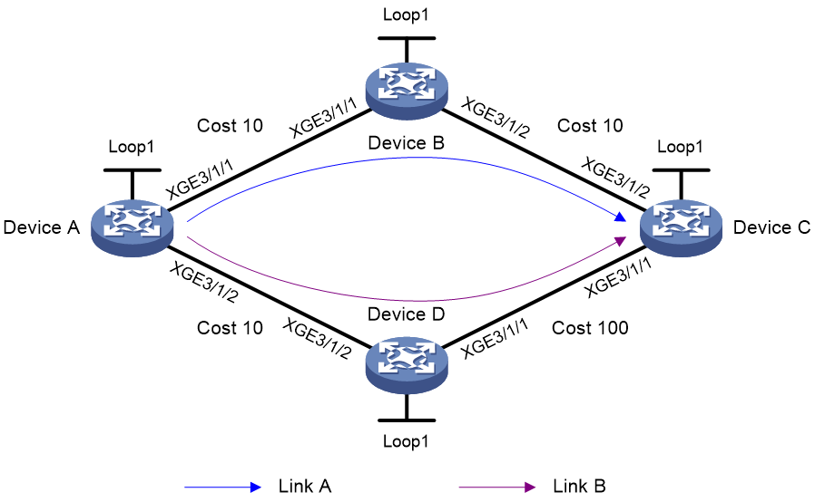
Table 1 Interface and IP address assignment
|
Device |
Interface |
IP address |
Device |
Interface |
IP address |
|
Device A |
Loop1 |
1::1/128 |
Device B |
Loop1 |
2::2/128 |
|
|
XGE3/1/1 |
2000:1::1/64 |
|
XGE3/1/1 |
2000:1::2/64 |
|
|
XGE3/1/2 |
2000:4::1/64 |
|
XGE3/1/2 |
2000:2::2/64 |
|
Device C |
Loop1 |
3::3/128 |
Device D |
Loop1 |
4::4/128 |
|
|
XGE3/1/1 |
2000:3::3/64 |
|
XGE3/1/1 |
2000:3::4/64 |
|
|
XGE3/1/2 |
2000:2::3/64 |
|
XGE3/1/2 |
2000:4::4/64 |
Procedure
1. Configure IPv6 addresses and prefixes for interfaces. (Details not shown.)
2. Configure Device A:
# Configure IPv6 IS-IS to achieve network level connectivity and set the IS-IS cost style to wide.
<DeviceA> system-view
[DeviceA] isis 1
[DeviceA-isis-1] network-entity 00.0000.0000.0001.00
[DeviceA-isis-1] cost-style wide
[DeviceA-isis-1] address-family ipv6
[DeviceA-isis-1-ipv6] quit
[DeviceA-isis-1] quit
[DeviceA] interface ten-gigabitethernet 3/1/1
[DeviceA-Ten-GigabitEthernet3/1/1] isis ipv6 enable 1
[DeviceA-Ten-GigabitEthernet3/1/1] isis cost 10
[DeviceA-Ten-GigabitEthernet3/1/1] quit
[DeviceA] interface ten-gigabitethernet 3/1/2
[DeviceA-Ten-GigabitEthernet3/1/2] isis ipv6 enable 1
[DeviceA-Ten-GigabitEthernet3/1/2] isis cost 10
[DeviceA-Ten-GigabitEthernet3/1/2] quit
[DeviceA] interface loopback 1
[DeviceA-LoopBack1] isis ipv6 enable 1
[DeviceA-LoopBack1] quit
# Enable SRv6 and configure a locator.
[DeviceA] segment-routing ipv6
[DeviceA-segment-routing-ipv6] locator aaa ipv6-prefix 11:: 64 static 32
[DeviceA-segment-routing-ipv6-locator-aaa] quit
[DeviceA-segment-routing-ipv6] quit
# Configure IPv6 IS-IS TI-LFA FRR and enable SR microloop avoidance.
[DeviceA] isis 1
[DeviceA-isis-1] address-family ipv6
[DeviceA-isis-1-ipv6] fast-reroute lfa
[DeviceA-isis-1-ipv6] fast-reroute ti-lfa
[DeviceA-isis-1-ipv6] fast-reroute microloop-avoidance enable
[DeviceA-isis-1-ipv6] segment-routing microloop-avoidance enable
# Apply the locator to the IPv6 IS-IS process.
[DeviceA-isis-1-ipv6] segment-routing ipv6 locator aaa
[DeviceA-isis-1-ipv6] quit
[DeviceA-isis-1] quit
3. Configure Device B:
# Configure IPv6 IS-IS to achieve network level connectivity and set the IS-IS cost style to wide.
<DeviceB> system-view
[DeviceB] isis 1
[DeviceB-isis-1] network-entity 00.0000.0000.0002.00
[DeviceB-isis-1] cost-style wide
[DeviceB-isis-1] address-family ipv6
[DeviceB-isis-1-ipv6] quit
[DeviceB-isis-1] quit
[DeviceB] interface ten-gigabitethernet 3/1/1
[DeviceB-Ten-GigabitEthernet3/1/1] isis ipv6 enable 1
[DeviceB-Ten-GigabitEthernet3/1/1] isis cost 10
[DeviceB-Ten-GigabitEthernet3/1/1] quit
[DeviceB] interface ten-gigabitethernet 3/1/2
[DeviceB-Ten-GigabitEthernet3/1/2] isis ipv6 enable 1
[DeviceB-Ten-GigabitEthernet3/1/2] isis cost 10
[DeviceB-Ten-GigabitEthernet3/1/2] quit
[DeviceB] interface loopback 1
[DeviceB-LoopBack1] isis ipv6 enable 1
[DeviceB-LoopBack1] quit
# Enable SRv6 and configure a locator.
[DeviceB] segment-routing ipv6
[DeviceB-segment-routing-ipv6] locator bbb ipv6-prefix 22:: 64 static 32
[DeviceB-segment-routing-ipv6-locator-bbb] quit
[DeviceB-segment-routing-ipv6] quit
# Configure IPv6 IS-IS TI-LFA FRR.
[DeviceB] isis 1
[DeviceB-isis-1] address-family ipv6
[DeviceB-isis-1-ipv6] fast-reroute lfa
[DeviceB-isis-1-ipv6] fast-reroute ti-lfa
# Apply the locator to the IPv6 IS-IS process.
[DeviceB-isis-1-ipv6] segment-routing ipv6 locator bbb
[DeviceB-isis-1-ipv6] quit
[DeviceB-isis-1] quit
4. Configure Device C:
# Configure IPv6 IS-IS to achieve network level connectivity and set the IS-IS cost style to wide.
<DeviceC> system-view
[DeviceC] isis 1
[DeviceC-isis-1] network-entity 00.0000.0000.0003.00
[DeviceC-isis-1] cost-style wide
[DeviceC-isis-1] address-family ipv6
[DeviceC-isis-1-ipv6] quit
[DeviceC-isis-1] quit
[DeviceC] interface ten-gigabitethernet 3/1/1
[DeviceC-Ten-GigabitEthernet3/1/1] isis ipv6 enable 1
[DeviceC-Ten-GigabitEthernet3/1/1] isis cost 100
[DeviceC-Ten-GigabitEthernet3/1/1] quit
[DeviceC] interface ten-gigabitethernet 3/1/2
[DeviceC-Ten-GigabitEthernet3/1/2] isis ipv6 enable 1
[DeviceC-Ten-GigabitEthernet3/1/2] isis cost 10
[DeviceC-Ten-GigabitEthernet3/1/2] quit
[DeviceC] interface loopback 1
[DeviceC-LoopBack1] isis ipv6 enable 1
[DeviceC-LoopBack1] quit
# Enable SRv6 and configure a locator.
[DeviceC] segment-routing ipv6
[DeviceC-segment-routing-ipv6] locator ccc ipv6-prefix 33:: 64 static 32
[DeviceC-segment-routing-ipv6-locator-ccc] quit
[DeviceC-segment-routing-ipv6] quit
# Configure IPv6 IS-IS TI-LFA FRR.
[DeviceC] isis 1
[DeviceC-isis-1] address-family ipv6
[DeviceC-isis-1-ipv6] fast-reroute lfa
[DeviceC-isis-1-ipv6] fast-reroute ti-lfa
# Apply the locator to the IPv6 IS-IS process.
[DeviceC-isis-1-ipv6] segment-routing ipv6 locator ccc
[DeviceC-isis-1-ipv6] quit
[DeviceC-isis-1] quit
5. Configure Device D:
# Configure IPv6 IS-IS to achieve network level connectivity and set the IS-IS cost style to wide.
<DeviceD> system-view
[DeviceD] isis 1
[DeviceD-isis-1] network-entity 00.0000.0000.0004.00
[DeviceD-isis-1] cost-style wide
[DeviceD-isis-1] address-family ipv6
[DeviceD-isis-1-ipv6] quit
[DeviceD-isis-1] quit
[DeviceD] interface ten-gigabitethernet 3/1/1
[DeviceD-Ten-GigabitEthernet3/1/1] isis ipv6 enable 1
[DeviceD-Ten-GigabitEthernet3/1/1] isis cost 100
[DeviceD-Ten-GigabitEthernet3/1/1] quit
[DeviceD] interface ten-gigabitethernet 3/1/2
[DeviceD-Ten-GigabitEthernet3/1/2] isis ipv6 enable 1
[DeviceD-Ten-GigabitEthernet3/1/2] isis cost 10
[DeviceD-Ten-GigabitEthernet3/1/2] quit
[DeviceD] interface loopback 1
[DeviceD-LoopBack1] isis ipv6 enable 1
[DeviceD-LoopBack1] quit
# Enable SRv6 and configure a locator.
[DeviceD] segment-routing ipv6
[DeviceD-segment-routing-ipv6] locator ddd ipv6-prefix 44:: 64 static 32
[DeviceD-segment-routing-ipv6-locator-ddd] quit
[DeviceD-segment-routing-ipv6] quit
# Configure IPv6 IS-IS TI-LFA FRR.
[DeviceD] isis 1
[DeviceD-isis-1] address-family ipv6
[DeviceD-isis-1-ipv6] fast-reroute lfa
[DeviceD-isis-1-ipv6] fast-reroute ti-lfa
# Apply the locator to the IPv6 IS-IS process.
[DeviceD-isis-1-ipv6] segment-routing ipv6 locator ddd
[DeviceD-isis-1-ipv6] quit
[DeviceD-isis-1] quit
Verifying the configuration
# Display IPv6 IS-IS routing information for 3::3/128.
[DeviceA] display isis route ipv6 3::3 128 verbose
Route information for IS-IS(1)
------------------------------
Level-1 IPv6 forwarding table
-----------------------------
IPv6 dest : 3::3/128
Flag : R/L/- Cost : 20
Admin tag : - Src count : 2
Nexthop : FE80::4449:7CFF:FEE0:206
NexthopFlag : -
Interface : XGE3/1/1
TI-LFA:
Interface : XGE3/1/2
BkNextHop : FE80::4449:91FF:FE42:407
LsIndex : 0x80000001
Backup label stack(top->bottom): {44::1:0:1}
Nib ID : 0x24000006
Flags: D-Direct, R-Added to Rib, L-Advertised in LSPs, U-Up/Down Bit Set
The output shows TI-LFA backup next hop information.
