- Table of Contents
-
- 04-Comware 7 CLI-based configuration examples (AC+fit AP deployment)
- 01-HTTPS Login Configuration Examples
- 02-SSH Configuration Examples
- 03-License Management Configuration Examples
- 04-AP Association with the AC at Layer 2 Configuration Examples
- 05-AP Association with the AC at Layer 2 (IPv6) Configuration Examples
- 06-Auto AP Configuration Examples
- 07-AP Association with the AC at Layer 3 Configuration Examples
- 08-AP Association with the AC at Layer 3 (IPv6) Configuration Examples
- 09-WEP Encryption Configuration Examples
- 100-Static Blacklist Configuration Examples
- 101-Client Quantity Control Configuration Examples
- 102-AP License Synchronization Configuration Examples
- 103-BLE Module iBeacon Transmission Configuration Examples
- 104-Medical RFID Tag Management Configuration Examples
- 105-iBeacon Management Configuration Examples
- 106-Mesh Link Establishment Between Fit APs Configuration Examples
- 107-Mesh Link Establishment Between a Fit AP and a Fat AP Configuration Examples
- 108-Auto-DFS and Auto-TPC Configuration Examples
- 109-AP Image Downloading Configuration Examples
- 10-PSK Encryption Configuration Examples
- 110-Dual-Uplink Interfaces Configuration Guide
- 111-H3C Comware AC Cloud-Managed AP Centralized Management Configuration Examples
- 112-Internal-to-External Access Through NAT Configuration Examples
- 113-Layer 2 Static Aggregation Configuration Examples
- 114-Layer 2 Multicast Configuration Examples
- 115-Static VLAN Allocation Configuration Examples
- 116-URL Redirection Configuration Examples
- 117-IPv6 URL Redirection Configuration Examples
- 11-WPA3-SAE PSK Encryption Configuration Examples
- 12-WLAN Access (IPv6) Configuration Examples
- 13-Policy-Based Forwarding with Dual Gateways Configuration Examples
- 14-Scheduled Configuration Deployment by AP Group Configuration Examples
- 15-Inter-AC Roaming with Static Client VLAN Allocation Configuration Examples
- 16-Service Template and Radio Binding Configuration Examples
- 17-Scheduled WLAN Access Services Configuration Examples
- 18-HTTPS-Based Local Portal Authentication Configuration Examples
- 19-Remote Portal Authentication Configuration Examples
- 20-Local Portal Authentication through LDAP Server Configuration Examples
- 21-Local Portal Auth and SSID-based Auth Page Pushing Configuration Examples
- 22-Local Portal MAC-Trigger Authentication Configuration Examples
- 23-Portal MAC-Trigger Authentication Configuration Examples
- 24-Local Forwarding Mode and Local Portal MAC-Trigger Auth Configuration Examples
- 25-Local Portal Authentication (IPv6) Configuration Examples
- 26-Local Portal Authentication through LDAP Server (IPv6) Configuration Examples
- 27-Remote Portal Authentication (IPv6) Configuration Examples
- 28-Portal MAC-Trigger Authentication (IPv6) Configuration Example
- 29-Remote Portal Authentication with User Profile Authorization Configuration Examples
- 30-WiFiDog Portal Authentication Configuration Examples
- 31-Portal Fail-Permit Configuration Examples
- 32-Local MAC Authentication Configuration Examples
- 33-Remote MAC Authentication Configuration Examples
- 34-Local Portal Authentication Configuration Examples
- 35-Transparent Auth Through Remote MAC and Portal Auth Configuration Examples
- 36-Remote AP, Remote Portal, and MAC-Trigger Authentication Configuration Examples
- 37-MAC Authentication with Guest VLAN Assignment Configuration Examples
- 38-MAC Authentication with Guest VLAN Assignment (IPv6) Configuration Examples
- 39-Local MAC-And-802.1X Authentication Configuration Examples
- 40-Local 802.1X Authentication Configuration Examples
- 41-Local RADIUS-Based 802.1X Authentication in EAP Relay Mode Configuration Examples
- 42-Remote 802.1X Authentication Configuration Examples
- 43-Remote 802.1X Authentication (IPv6) Configuration Examples
- 44-Remote 802.1X Authentication in WPA3-Enterprise Mode Configuration Examples
- 45-802.1X Auth with ACL Assignment Through IMC Server Configuration Examples
- 46-802.1X Auth with User Profile Assignment Through IMC Server Configuration Examples
- 47-EAD Authentication Configuration Examples
- 48-EAD Authentication (IPv6) Configuration Examples
- 49-Local Forwarding Mode and Local Portal Authentication Configuration Examples
- 50-Local Forwarding Mode Direct Portal Authentication Configuration Examples
- 51-Local Forwarding Mode Direct Portal Authentication (IPv6) Configuration Examples
- 52-Local Forwarding Configuration Examples
- 53-Wired Port Local Forwarding through Wireless Terminator Configuration Examples
- 54-Remote AP Configuration Examples
- 55-Downlink VLAN Management for Fit-Mode APs Configuration Examples
- 56-Downlink VLAN Management for Fit APs and Cloud APs Configuration Examples
- 57-WIPS Configuration Examples
- 58-WIPS Countermeasures Against All SSIDs Configuration Examples
- 59-IP Source Guard (IPv4) Configuration Examples
- 60-IP Source Guard (IPv6) Configuration Examples
- 61-IPS Configuration Examples
- 62-URL Filtering Configuration Examples
- 63-Anti-Virus Configuration Examples
- 64-Data Filtering Configuration Examples
- 65-File Filtering Configuration Examples
- 66-Application Audit and Management Configuration Examples
- 67-Application Rate Limiting Configuration Examples
- 68-IRF Setup with LACP MAD Configuration Examples
- 69-IRF Setup with ARP MAD Configuration Examples
- 70-IRF Setup with Members Not Directly Connected Configuration Examples
- 71-IRF Setup with Members in One Chassis Configuration Examples
- 72-IRF Setup with Members in Different Chassis Configuration Examples
- 73-Dual-Link Backup Configuration Examples
- 74-Remote 802.1X Auth on an AC Hierarchy Network with Dual-Link Backup Configuration Examples
- 75-Remote Portal Auth on an AC Hierarchy Network with Dual-Link Backup Configuration Examples
- 76-OAuth-Based Portal MAC-Trigger Auth on a Local-Forwarding Dual-Link Backup Configuration Examples
- 77-Dual-Link Backup OAuth-Based Portal Authentication in Local Forwarding Configuration Examples
- 78-Dual-Link Backup Remote Portal MAC-Trigger Authentication in Local Forwarding Configuration Examples
- 79-Dual-Link Backup Remote Portal and Transparent MAC Auth in Local Forwarding Configuration Examples
- 80-Dual-Link Backup Remote Portal Authentication in Local Forwarding Configuration Examples
- 81-Dual-Link Backup Remote Portal and Transparent MAC Auth in Centralized Forwarding Configuration Examples
- 82-Dual-Link Backup Remote Portal Authentication in Centralized Forwarding Configuration Examples
- 83-Dual-Link Backup Lightweight Portal Authentication in Centralized Forwarding Configuration Examples
- 84-Dual-Link Backup OAuth-Based Portal Authentication in Centralized Forwarding Configuration Examples
- 85-Dual-Link Backup Remote Portal MAC-Trigger Auth in Centralized Forwarding Configuration Examples
- 86-Remote 802.1X Authentication on a Dual-Link AC Backup Network Configuration Examples
- 87-Remote MAC Authentication on a Dual-Link AC Backup Network Configuration Examples
- 88-AC Hierarchy Configuration Examples
- 89-Remote 802.1X Auth (Local AC Auth+AC Forwardering) Configuration Examples
- 90-Remote 802.1X Auth (Central AC Auth+AP Forwarding) Configuration Examples
- 91-AC Hierarchy (IPv6) Configuration Examples
- 92-WLAN Probe Configuration Examples
- 93-Multicast Optimization Configuration Examples
- 94-Client Rate Limiting Configuration Examples
- 95-Inter-AC Roaming Configuration Examples
- 96-Inter-AC Roaming (IPv6) Configuration Examples
- 97-Inter-AC Roaming in Local Forwarding Mode Configuration Examples
- 98-H3C Access Controllers Cooperative Roaming for 802.11v Clients Configuration Examples
- Related Documents
-
| Title | Size | Download |
|---|---|---|
| 88-AC Hierarchy Configuration Examples | 468.83 KB |
|
|
|
H3C Access Controllers |
|
AC Hierarchy Configuration Examples |
|
|
|
|
Copyright © 2023 New H3C Technologies Co., Ltd. All rights reserved.
No part of this manual may be reproduced or transmitted in any form or by any means without prior written consent of New H3C Technologies Co., Ltd.
Except for the trademarks of New H3C Technologies Co., Ltd., any trademarks that may be mentioned in this document are the property of their respective owners.
The information in this document is subject to change without notice.
Introduction
The following information provides an AC hierarchy configuration example.
Prerequisites
This document applies to Comware-based access controllers and access points. Procedures and information in the examples might be slightly different depending on the software or hardware version of the access controllers and access points.
The configuration examples were created and verified in a lab environment, and all the devices were started with the factory default configuration. When you are working on a live network, make sure you understand the potential impact of every command on your network.
The following information is provided based on the assumption that you have basic knowledge of AC hierarchy, portal, WLAN access, and AP management.
Example: Configuring AC hierarchy
Network configuration
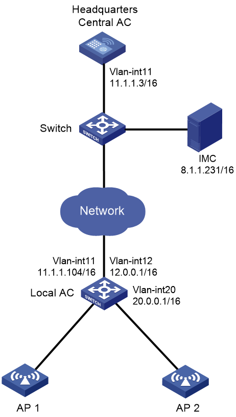
As shown in Figure 1, the central AC is deployed at the headquarters and a local AC (a unified wired and wireless AC) is deployed at the branch. The central AC performs client authentication and the local AC forwards client traffic.
Configure network settings to meet the following requirements:
· APs obtain the IP address of the central AC through DHCP Option 43 and establish CAPWAP tunnels with the local AC after AC rediscovery.
· The IMC server acts as the portal server and AAA server to perform client portal authentication.
· The local AC acts as the DHCP server to assign IP addresses to APs and clients.
Analysis
· For the AP to discover the AC across the Internet, configure Option 43 and manually specify the IP address of the AC on Router A.
· For interface GigabitEthernet1/0/1 on an AP to join the local-forwarding VLAN, use a text editor to create an AP configuration file and upload the file to the central AC.
· With AC rediscovery enabled, the APs might fail to come online through the local AC in the branch if the local AC does not have the lowest workload. For the central AC to assign the local AC to the APs at AC rediscovery, specify the local AC for APs.
Restrictions and guidelines
When you configure AC hierarchy, follow these restrictions and guidelines:
· Use the actual serial ID of an AP to uniquely identify that AP.
· Do not configure any portal settings on the local AC when portal authentication and local forwarding are used in the AC hierarchy network.
· Do not enable auto AP on the local AC, and do not create APs on the local AC if the APs are to be managed centrally by the central AC.
· Disable firmware upgrade for the local AC because the S5560 unified wired and wireless AC and the access controller module have different software versions.
· The URL of the portal Web server redirected to clients does not carry parameters by default. You must configure the parameters manually.
· Central ACs do not support IRF.
Procedures
Configuring the central AC
1. Make sure the devices can reach each other. (Details not shown.)
2. Create AP configuration file map.txt as follows and then upload the file to the central AC.
system-view
vlan 20
interface GigabitEthernet1/0/1
port link-type trunk
port trunk permit vlan 20
3. Create VLAN 11 and VLAN-interface 11, and assign an IP address to the VLAN interface.
<Central AC> system-view
[Central AC] vlan 11
[Central AC-vlan11] quit
[Central AC] interface vlan-interface 11
[Central AC-Vlan-interface11] ip address 11.1.1.3 16
[Central AC-Vlan-interface11] quit
4. Configure GigabitEthernet 1/0/1 that connects the central AC to the switch as a trunk port, and assign the port to VLAN 11.
[Central AC] interface gigabitethernet 1/0/1
[Central AC-GigabitEthernet1/0/1] port link-type trunk
[Central AC-GigabitEthernet1/0/1] port trunk permit vlan 11
[Central AC-GigabitEthernet1/0/1] quit
5. Create local AC 55ng-1, and specify the serial ID of the local AC.
[Central AC] wlan local-ac name 55ng-1 model S5560
[Central AC-wlan-local-ac-55ng-1] serial-id 210235A1GCH147000017
[Central AC-wlan-local-ac-55ng-1] quit
6. Configure the RADIUS scheme for portal authentication:
# Create RADIUS scheme imc.
[Central AC] radius scheme imc
# Specify the IP address of the primary authentication server as 8.1.1.231.
[Central AC-radius-imc] primary authentication 8.1.1.231
# Specify the IP address of the primary accounting server as 8.1.1.231.
[Central AC-radius-imc] primary accounting 8.1.1.231
# Set the shared key to 12345678 in plaintext form for secure authentication communication.
[Central AC-radius-imc] key authentication simple 12345678
# Set the shared key to 12345678 in plaintext form for secure accounting communication.
[Central AC-radius-imc] key accounting simple 12345678
# Configure the central AC to remove the domain name from the usernames sent to the RADIUS servers.
[Central AC-radius-imc] user-name-format without-domain
# Specify IP address 11.1.1.3 as the source IP address of outgoing RADIUS packets.
[Central AC-radius-imc] nas-ip 11.1.1.3
[Central AC-radius-imc] quit
7. Configure the authentication domain for portal authentication:
# Create domain imc and enter its view.
[Central AC] domain imc
# Perform RADIUS authentication for portal users based on scheme imc.
[Central AC-isp-imc] authentication portal radius-scheme imc
# Perform RADIUS authorization for portal users based on scheme imc.
[Central AC-isp-imc] authorization portal radius-scheme imc
# Perform RADIUS accounting for portal users based on scheme imc.
[Central AC-isp-imc] accounting portal radius-scheme imc
[Central AC-isp-imc] quit
8. Configure the portal authentication server:
# Create portal authentication server imc and enter its view.
[Central AC] portal server imc
# Configure the IP address of the portal authentication server as 8.1.1.231 and the plaintext key as 12345678.
[Central AC-portal-server-imc] ip 8.1.1.231 key simple 12345678
9. Configure the portal Web server:
# Create portal Web server imc and enter its view.
[Central AC-portal-server-imc] portal web-server imc
# Configure the URL for the portal Web server as http://8.1.1.231:8080/portal.
[Central AC-portal-server-imc] url http://8.1.1.231:8080/portal
# Configure the parameters carried in the URL of the portal Web server.
[Central AC-portal-server-imc] url-parameter apmac ap-mac
[Central AC-portal-server-imc] url-parameter ssid ssid
[Central AC-portal-server-imc] url-parameter userip source-address
[Central AC-portal-server-imc] url-parameter usermac source-mac
[Central AC-portal-server-imc] quit
# Enable validity check on wireless portal clients.
[Central AC] portal host-check enable
10. Configure wireless services:
# Create service template portal.
[Central AC] wlan service-template portal
# Set the SSID for the service template to portal.
[Central AC-wlan-st-portal] ssid portal
# Set the AKM mode to PSK, and specify the plaintext preshared key as 12345678.
[Central AC-wlan-st-portal] akm mode psk
[Central AC-wlan-st-portal] preshared-key pass-phrase simple 12345678
# Set the cipher suite to CCMP and the security IE to RSN.
[Central AC-wlan-st-portal] cipher-suite ccmp
[Central AC-wlan-st-portal] security-ie rsn
# Assign clients coming online through the service template to VLAN 20.
[Central AC-wlan-st-portal] vlan 20
# Enable APs to forward client traffic. If the APs act as the client traffic forwarder by default, skip this step.
[Central AC-wlan-st-portal] client forwarding-location ap
# Enable direct IPv4 portal authentication on the service template.
[Central AC-wlan-st-portal] portal enable method direct
# Specify the authentication domain as imc for IPv4 portal users on the service template.
[Central AC-wlan-st-portal] portal domain imc
# Configure the BAS-IP attribute as 11.1.1.3 for portal packets sent to the portal authentication server.
[Central AC-wlan-st-portal] portal bas-ip 11.1.1.3
# Apply IPv4 portal Web server imc on the service template for portal authentication.
[Central AC-wlan-st-portal] portal apply web-server imc
# Enable the service template.
[Central AC-wlan-st-portal] service-template enable
[Central AC-wlan-st-portal] quit
# Create AP ap1 and set the serial ID to 210235A1SVC15C000028.
[Central AC] wlan ap ap1 model WA6320
[Central AC-wlan-ap-ap1] serial-id 219801A28N819CE0002T
[Central AC-wlan-ap-ap1] quit
# Create AP group group1 and configure a grouping rule by AP name to add AP ap1 to the group.
[Central AC] wlan ap-group group1
[Central AC-wlan-ap-group-group1] ap ap1
|
|
NOTE: In a large-scale network, configure AP settings in AP group view instead of AP view as a best practice. |
# Bind service template portal to radio 1.
[Central AC-wlan-ap-group-group1] ap-model WA6320
[Central AC-wlan-ap-group-group1-ap-model-WA6320] radio 1
[Central AC-wlan-ap-group-group1-ap-model-WA6320-radio-1] service-template portal
# Enable radio 1.
[Central AC-wlan-ap-group-group1-ap-model-WA6320-radio-1] radio enable
[Central AC-wlan-ap-group-group1-ap-model-WA6320-radio-1] quit
# Bind service template portal to radio 2.
[Central AC-wlan-ap-group-group1-ap-model-WA6320] radio 2
[Central AC-wlan-ap-group-group1-ap-model-WA6320-radio-2] service-template portal
# Enable radio 2.
[Central AC-wlan-ap-group-group1-ap-model-WA6320-radio-2] radio enable
[Central AC-wlan-ap-group-group1-ap-model-WA6320-radio-2] quit
# Deploy configuration file map.txt to AP ap1.
[Central AC-wlan-ap-group-group1-ap-model-WA6320] map-configuration cfa0:/map.txt
[Central AC-wlan-ap-group-group1-ap-model-WA6320] quit
# Enable AC rediscovery.
[Central AC-wlan-ap-group-group1] control-address enable
# Specify the local AC with IP address 11.1.1.104 for the AP.
[Central AC-wlan-ap-group-group1] control-address ip 11.1.1.104
Configuring the local AC
1. Configure the local AC feature:
# Enable the local AC feature.
<Local AC> system-view
[Local AC] wlan local-ac enable
# Specify the central AC with IP address 11.1.1.3 for the local AC.
[Local AC] wlan central-ac ip 11.1.1.3
# Configure the local AC to use VLAN 11 to establish a tunnel with the central AC.
[Local AC] wlan local-ac capwap source-vlan 11
2. Configure DHCP:
# Enable DHCP.
[Local AC] dhcp enable
# Create DHCP address pool ap, specify the gateway address as 12.0.0.1, and specify the subnet for dynamic allocation as 12.0.0.0/16.
[Local AC] dhcp server ip-pool ap
[Local AC-dhcp-pool-ap] gateway-list 12.0.0.1
[Local AC-dhcp-pool-ap] network 12.0.0.0 mask 255.255.0.0
# Configure Option 43 that specifies a DNS server address 11.1.1.3 in the DHCP address pool.
[Local AC-dhcp-pool-ap] option 43 hex 80070000010b010103
[Local AC-dhcp-pool-ap] quit
# Create DHCP address pool client, specify the gateway address as 20.0.0.1, and specify the subnet for dynamic allocation as 20.0.0.0/16.
[Local AC] dhcp server ip-pool client
[Local AC-dhcp-pool-ap] gateway-list 20.0.0.1
[Local AC-dhcp-pool-ap] network 20.0.0.0 mask 255.255.0.0
[Local AC-dhcp-pool-ap] quit
3. Configure VLAN interfaces:
# Create VLAN 11 and VLAN-interface 11, and assign an IP address to the interface. The local AC uses this interface to associate with the central AC.
[Local AC] vlan 11
[Local AC-vlan11] quit
[Local AC] interface Vlan-interface11
[Local AC-Vlan-interface11] ip address 11.1.1.104 255.255.0.0
[Local AC-Vlan-interface11] quit
# Create VLAN 12 and VLAN-interface 12, and assign an IP address to the interface. The local AC uses this interface to associate with APs.
[Local AC] vlan 12
[Local AC-vlan12] quit
[Local AC] interface Vlan-interface12
[Local AC-Vlan-interface12] ip address 12.0.0.1 255.255.0.0
[Local AC-Vlan-interface12] dhcp server apply ip-pool ap
[Local AC-Vlan-interface12] quit
# Create VLAN 20 and VLAN-interface 20, and assign an IP address to the interface. The local AC uses this interface to provide access to clients.
[Local AC] vlan 20
[Local AC-vlan20] quit
[Local AC] interface Vlan-interface20
[Local AC-Vlan-interface20] ip address 20.0.0.1 255.255.0.0
[Local AC-Vlan-interface20] dhcp server apply ip-pool client
[Local AC-Vlan-interface20] quit
# Configure GigabitEthernet 1/0/1 that connects the local AC to AP 1 as a trunk port, assign the port to VLAN 12 and VLAN 20, and set the PVID to 12.
[Local AC] interface GigabitEthernet 1/0/1
[Local AC-GigabitEthernet1/0/1] port link-type trunk
[Local AC-GigabitEthernet1/0/1] port trunk permit vlan 12 20
[Local AC-GigabitEthernet1/0/1] port trunk pvid vlan 12
[Local AC-GigabitEthernet1/0/1] quit
# Configure GigabitEthernet 1/0/2 that connects the local AC to AP 2 as a trunk port, assign the port to VLAN 12 and VLAN 20, and set the PVID to 12.
[Local AC] interface GigabitEthernet 1/0/2
[Local AC-GigabitEthernet1/0/2] port link-type trunk
[Local AC-GigabitEthernet1/0/2] port trunk permit vlan 12 20
[Local AC-GigabitEthernet1/0/2] port trunk pvid vlan 12
[Local AC-GigabitEthernet1/0/2] quit
# Configure GigabitEthernet 1/0/3 that connects the local AC to the headquarters as a trunk port, and assign the port to VLAN 11, VLAN 12, and VLAN 20.
[Local AC] interface GigabitEthernet 1/0/3
[Local AC-GigabitEthernet1/0/3] port link-type trunk
[Local AC-GigabitEthernet1/0/3] port trunk permit vlan 11 12 20
[Local AC-GigabitEthernet1/0/3] quit
Configuring the IMC server
This example uses the IMC server to describe the RADIUS server and portal server configuration. The IMC server runs on IMC PLAT 7.2 (E0403p10), IMC EIA 7.2 (E0405), and IMC EIP 7.2 (E0405).
To configure the IMC server:
1. Log in to IMC and click the User tab.
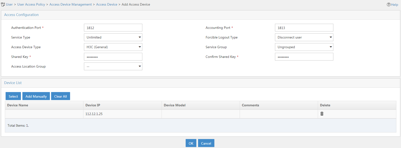
2. Add an access device.
a. In the left navigation pane, select User Access Policy > Access Device Management > Access Device.
b. Click Add.
The Add Access Device page opens.
c. In the Device List area, click Add Manually, and specify the start IP address as 11.1.1.3.
d. In the Access Configuration area, configure the following parameters:
- Enter radius in the Shared Key and Confirm Shared Key fields.
The key is consistent with the shared key configured on the AC.
- Use the default values for other parameters.
e. Click OK.
Figure 2 Adding an access device
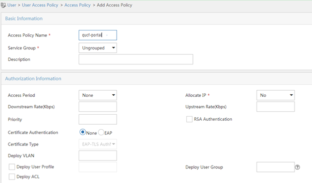
3. Add an access policy:
a. From the navigation pane, select User Access Policy > Access Policy.
b. Click Add.
c. On the Add Access Policy page, configure the following parameters:
- Enter the policy name.
- Select the service group.
- Use the default values for other parameters.
Figure 3 Adding an access policy

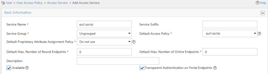
4. Add an access service:
a. From the navigation pane, select User Access Policy > Access Service.
b. Click Add.
c. On the Add Access Service page, configure the following parameters:
- Enter the service name.
- Use the default values for other parameters.
d. Click OK.
Figure 4 Adding an access service
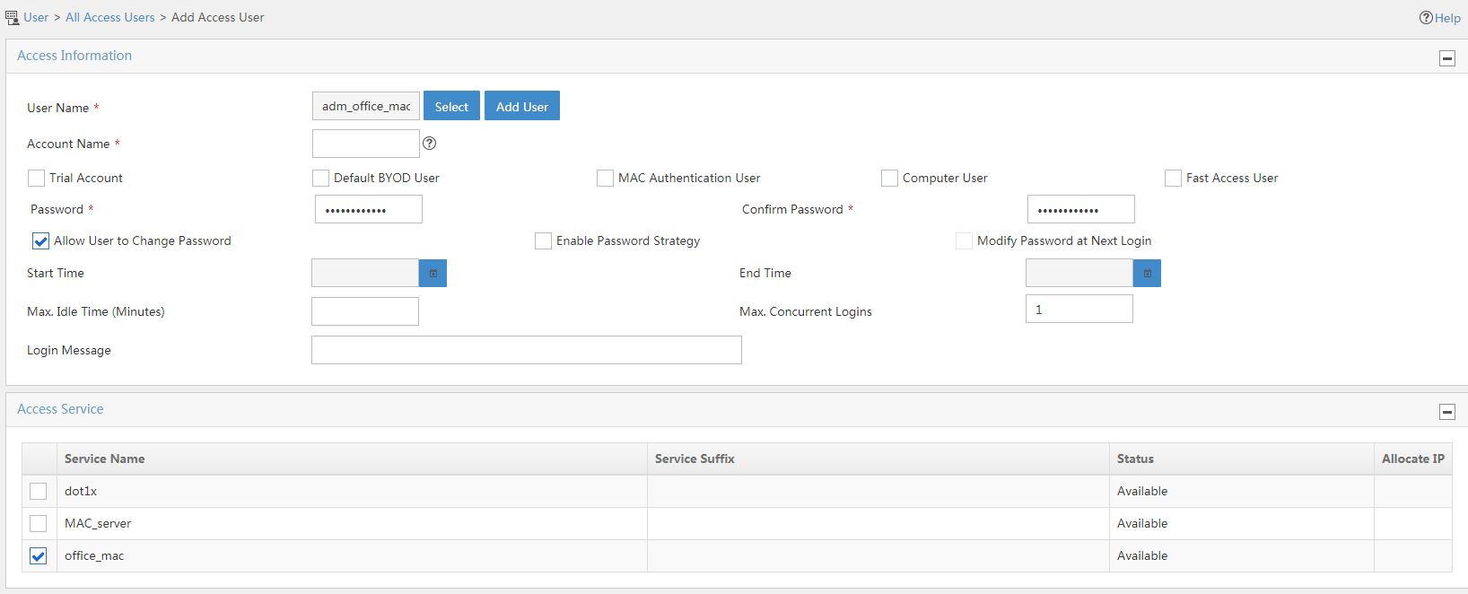
5. Add an access user:
a. From the navigation pane, select Access User > Access User.
b. Click Add.
c. In the Access Information area, add a user:
- Select a user.
- Set the password.
d. Click OK.
Figure 5 Adding an access user
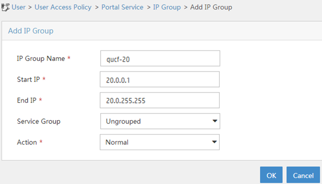
6. Create an IP group:
a. From the navigation pane, select User Access Policy > Portal Service > IP Group.
b. Click Add.
c. Configure the following parameters:
- IP Group Name—Enter the IP group name.
- Start IP—Enter the start IP address of the IP group. Make sure the client IP address is in the IP group.
- End IP—Enter the end IP address of the IP group. Make sure the client IP address is in the IP group.
- Service Group—Select a service group. This example uses the default value Ungrouped.
- Action—Select Normal.
d. Click OK.
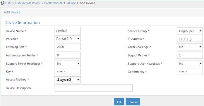
7. Add a portal device:
a. From the navigation pane, select User Access Policy > Portal Service > Device.
b. Click Add.
c. Configure the following parameters:
- Device Name—Enter the device name.
- Version—Select CMCC 1.0.
- IP Address—Enter the IP address of the AC's interface connected to the client.
- Support Server Heartbeat—Select whether to support the portal server heartbeat function. In this example, select No.
- Support User Heartbeat—Select whether to support the portal user heartbeat function. In this example, select No.
- Key—Enter the key. The key must be the same as that configured on the AC.
- Access Method—Select layer 3.
Use the default settings for other parameters.
d. Click OK.
Figure 7 Adding a portal device
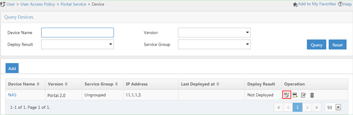
8. Associate the portal device with the IP group:
a. Click the Port Group icon ![]() in the Operation field for device NAS to open the port group
configuration page.
in the Operation field for device NAS to open the port group
configuration page.
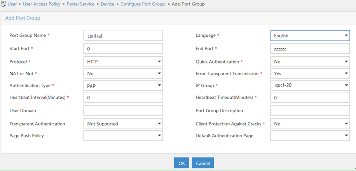
b. Click Add.
c. Configure the following parameters:
- Port Group Name—Enter the port group name.
- IP Group—Select the configured IP group. The IP address used by the user to access the network must be within this IP address group.
Use the default settings for other parameters.
d. Click OK.
Verifying the configuration
# Verify that the local AC is in R/M state on the central AC. This state indicates that the local AC has come online on the central AC.
[Central AC] display wlan local-ac name 55ng-1
Local AC Information
State : I = Idle, J = Join, JA = JoinAck, IL = ImageLoad
C = Config, DC = DataCheck, R = Run
AC name ACID State Model Serial ID
55ng-1 2 R/M S5560 210235A1GCH147000017
# Verify that the AP is in R/M state on the central AC.
[Central AC] display wlan ap all
Total number of APs: 1
Total number of connected APs: 1
Total number of connected manual APs: 1
Total number of connected auto APs: 0
Total number of connected common APs: 1
Total number of connected WTUs: 0
Total number of inside APs: 0
Maximum supported APs: 4096
Remaining APs: 4095
Total AP licenses: 512
Local AP licenses: 512
Server AP licenses: 0
Remaining local AP licenses: 511
Sync AP licenses: 0
AP information
State : I = Idle, J = Join, JA = JoinAck, IL = ImageLoad
C = Config, DC = DataCheck, R = Run, M = Master, B = Backup
AP name APID State Model Serial ID
ap1 8 R/M WA6320 219801A28N819CE0002T
# Verify that the AP has associated with the local AC.
[Central AC] display wlan ap-distribution all
Central AC
Slot : 1
Total Number of APs: 0
AP name :
Local AC
Name : 55ng-1
Total Number of APs: 1
AP name : ap1
# Verify that a client has come online.
[Central AC] display wlan client
Total number of clients: 1
MAC address User name AP name RID IP address IPv6 address VLAN
c81e-e738-016a N/A ap1 1 20.0.0.3 20
# Verify that the client has passed portal authentication.
[Central AC] display portal user all
Total portal users: 1
Username: qcf
AP name: ap1
Radio ID: 1
SSID: portal
Portal server: imc
State: Online
VPN instance: N/A
MAC IP VLAN Interface
c81e-e738-016a 20.0.0.3 20 WLAN-BSS1/0/10
Authorization information:
DHCP IP pool: N/A
User profile: N/A
Session group profile: N/A
ACL number: N/A
Inbound CAR: N/A
Outbound CAR: N/A
Configuration files
· Central AC:
#
vlan 11
#
wlan service-template portal
ssid portal
vlan 20
client forwarding-location ap
akm mode psk
preshared-key pass-phrase cipher $c$3$p0PjuXJ5pGfJ6Z1XDkGRsPR8JoPhrP60GyRn
cipher-suite ccmp
security-ie rsn
portal enable method direct
portal domain imc
portal bas-ip 11.1.1.3
portal apply web-server imc
service-template enable
#
interface Vlan-interface11
ip address 11.1.1.3 255.255.0.0
#
interface GigabitEthernet1/0/1
port link-type trunk
port trunk permit vlan 11
#
radius scheme imc
primary authentication 8.1.1.231
primary accounting 8.1.1.231
key authentication cipher $c$3$t7x0fIARso0US949SnQS2pq53eIdsgUr6z07
key accounting cipher $c$3$V4YI3sDOEq0VqAIPoaNjQOV3ZalvqTL05GC0
user-name-format without-domain
nas-ip 11.1.1.3
#
domain imc
authentication portal radius-scheme imc
authorization portal radius-scheme imc
accounting portal radius-scheme imc
#
portal host-check enable
#
portal web-server imc
url http://8.1.1.231:8080/portal
url-parameter apmac ap-mac
url-parameter ssid ssid
url-parameter userip source-address
url-parameter usermac source-mac
#
portal server imc
ip 8.1.1.231 key cipher $c$3$76rxh0Qxgg0I1zWtzrlr2r0ch76JC+3IZK2A
#
wlan ap ap1 model WA6320
serial-id 219801A28N819CE0002T
#
wlan ap-group group1
control-address enable
control-address ip 11.1.1.104
ap ap1
ap-model WA6320
map-configuration cfa0:/map.txt
radio 1
radio enable
service-template portal
radio 2
radio enable
service-template portal
#
wlan local-ac name 55ng-1 model S5560
serial-id 210235A1GCH147000017
#
· Local AC:
#
dhcp enable
#
vlan 11 to 12
#
vlan 20
#
dhcp server ip-pool ap
gateway-list 12.0.0.1
network 12.0.0.0 mask 255.255.0.0
option 43 hex 80070000010b010103
#
dhcp server ip-pool client
gateway-list 20.0.0.1
network 20.0.0.0 mask 255.255.0.0
#
interface Vlan-interface11
ip address 11.1.1.104 255.255.0.0
#
interface Vlan-interface12
ip address 12.0.0.1 255.255.0.0
dhcp server apply ip-pool ap
#
interface Vlan-interface20
ip address 20.0.0.1 255.255.0.0
dhcp server apply ip-pool client
#
interface GigabitEthernet1/0/1
port link-type trunk
port trunk permit vlan 12 20
port trunk pvid vlan 12
#
interface GigabitEthernet1/0/2
port link-type trunk
port trunk permit vlan 12 20
port trunk pvid vlan 12
#
interface GigabitEthernet1/0/3
port link-type trunk
port trunk permit vlan 11 12 20
#
wlan local-ac enable
wlan local-ac capwap source-vlan 11
#
wlan central-ac ip 11.1.1.3
Related documentation
· AC Hierarchy Command Reference in H3C Access Controllers Command References
· AC Hierarchy Configuration Guide in H3C Access Controllers Configuration Guides
· User Access and Authentication Command Reference in H3C Access Controllers Command References
· User Access and Authentication Configuration Guide in H3C Access Controllers Configuration Guides
· WLAN Access Command Reference in H3C Access Controllers Command References
· WLAN Access Configuration Guide in H3C Access Controllers Configuration Guides
