- Table of Contents
-
- 04-Comware 7 CLI-based configuration examples (AC+fit AP deployment)
- 01-HTTPS Login Configuration Examples
- 02-SSH Configuration Examples
- 03-License Management Configuration Examples
- 04-AP Association with the AC at Layer 2 Configuration Examples
- 05-AP Association with the AC at Layer 2 (IPv6) Configuration Examples
- 06-Auto AP Configuration Examples
- 07-AP Association with the AC at Layer 3 Configuration Examples
- 08-AP Association with the AC at Layer 3 (IPv6) Configuration Examples
- 09-WEP Encryption Configuration Examples
- 100-Static Blacklist Configuration Examples
- 101-Client Quantity Control Configuration Examples
- 102-AP License Synchronization Configuration Examples
- 103-BLE Module iBeacon Transmission Configuration Examples
- 104-Medical RFID Tag Management Configuration Examples
- 105-iBeacon Management Configuration Examples
- 106-Mesh Link Establishment Between Fit APs Configuration Examples
- 107-Mesh Link Establishment Between a Fit AP and a Fat AP Configuration Examples
- 108-Auto-DFS and Auto-TPC Configuration Examples
- 109-AP Image Downloading Configuration Examples
- 10-PSK Encryption Configuration Examples
- 110-Dual-Uplink Interfaces Configuration Guide
- 111-H3C Comware AC Cloud-Managed AP Centralized Management Configuration Examples
- 112-Internal-to-External Access Through NAT Configuration Examples
- 113-Layer 2 Static Aggregation Configuration Examples
- 114-Layer 2 Multicast Configuration Examples
- 115-Static VLAN Allocation Configuration Examples
- 116-URL Redirection Configuration Examples
- 117-IPv6 URL Redirection Configuration Examples
- 11-WPA3-SAE PSK Encryption Configuration Examples
- 12-WLAN Access (IPv6) Configuration Examples
- 13-Policy-Based Forwarding with Dual Gateways Configuration Examples
- 14-Scheduled Configuration Deployment by AP Group Configuration Examples
- 15-Inter-AC Roaming with Static Client VLAN Allocation Configuration Examples
- 16-Service Template and Radio Binding Configuration Examples
- 17-Scheduled WLAN Access Services Configuration Examples
- 18-HTTPS-Based Local Portal Authentication Configuration Examples
- 19-Remote Portal Authentication Configuration Examples
- 20-Local Portal Authentication through LDAP Server Configuration Examples
- 21-Local Portal Auth and SSID-based Auth Page Pushing Configuration Examples
- 22-Local Portal MAC-Trigger Authentication Configuration Examples
- 23-Portal MAC-Trigger Authentication Configuration Examples
- 24-Local Forwarding Mode and Local Portal MAC-Trigger Auth Configuration Examples
- 25-Local Portal Authentication (IPv6) Configuration Examples
- 26-Local Portal Authentication through LDAP Server (IPv6) Configuration Examples
- 27-Remote Portal Authentication (IPv6) Configuration Examples
- 28-Portal MAC-Trigger Authentication (IPv6) Configuration Example
- 29-Remote Portal Authentication with User Profile Authorization Configuration Examples
- 30-WiFiDog Portal Authentication Configuration Examples
- 31-Portal Fail-Permit Configuration Examples
- 32-Local MAC Authentication Configuration Examples
- 33-Remote MAC Authentication Configuration Examples
- 34-Local Portal Authentication Configuration Examples
- 35-Transparent Auth Through Remote MAC and Portal Auth Configuration Examples
- 36-Remote AP, Remote Portal, and MAC-Trigger Authentication Configuration Examples
- 37-MAC Authentication with Guest VLAN Assignment Configuration Examples
- 38-MAC Authentication with Guest VLAN Assignment (IPv6) Configuration Examples
- 39-Local MAC-And-802.1X Authentication Configuration Examples
- 40-Local 802.1X Authentication Configuration Examples
- 41-Local RADIUS-Based 802.1X Authentication in EAP Relay Mode Configuration Examples
- 42-Remote 802.1X Authentication Configuration Examples
- 43-Remote 802.1X Authentication (IPv6) Configuration Examples
- 44-Remote 802.1X Authentication in WPA3-Enterprise Mode Configuration Examples
- 45-802.1X Auth with ACL Assignment Through IMC Server Configuration Examples
- 46-802.1X Auth with User Profile Assignment Through IMC Server Configuration Examples
- 47-EAD Authentication Configuration Examples
- 48-EAD Authentication (IPv6) Configuration Examples
- 49-Local Forwarding Mode and Local Portal Authentication Configuration Examples
- 50-Local Forwarding Mode Direct Portal Authentication Configuration Examples
- 51-Local Forwarding Mode Direct Portal Authentication (IPv6) Configuration Examples
- 52-Local Forwarding Configuration Examples
- 53-Wired Port Local Forwarding through Wireless Terminator Configuration Examples
- 54-Remote AP Configuration Examples
- 55-Downlink VLAN Management for Fit-Mode APs Configuration Examples
- 56-Downlink VLAN Management for Fit APs and Cloud APs Configuration Examples
- 57-WIPS Configuration Examples
- 58-WIPS Countermeasures Against All SSIDs Configuration Examples
- 59-IP Source Guard (IPv4) Configuration Examples
- 60-IP Source Guard (IPv6) Configuration Examples
- 61-IPS Configuration Examples
- 62-URL Filtering Configuration Examples
- 63-Anti-Virus Configuration Examples
- 64-Data Filtering Configuration Examples
- 65-File Filtering Configuration Examples
- 66-Application Audit and Management Configuration Examples
- 67-Application Rate Limiting Configuration Examples
- 68-IRF Setup with LACP MAD Configuration Examples
- 69-IRF Setup with ARP MAD Configuration Examples
- 70-IRF Setup with Members Not Directly Connected Configuration Examples
- 71-IRF Setup with Members in One Chassis Configuration Examples
- 72-IRF Setup with Members in Different Chassis Configuration Examples
- 73-Dual-Link Backup Configuration Examples
- 74-Remote 802.1X Auth on an AC Hierarchy Network with Dual-Link Backup Configuration Examples
- 75-Remote Portal Auth on an AC Hierarchy Network with Dual-Link Backup Configuration Examples
- 76-OAuth-Based Portal MAC-Trigger Auth on a Local-Forwarding Dual-Link Backup Configuration Examples
- 77-Dual-Link Backup OAuth-Based Portal Authentication in Local Forwarding Configuration Examples
- 78-Dual-Link Backup Remote Portal MAC-Trigger Authentication in Local Forwarding Configuration Examples
- 79-Dual-Link Backup Remote Portal and Transparent MAC Auth in Local Forwarding Configuration Examples
- 80-Dual-Link Backup Remote Portal Authentication in Local Forwarding Configuration Examples
- 81-Dual-Link Backup Remote Portal and Transparent MAC Auth in Centralized Forwarding Configuration Examples
- 82-Dual-Link Backup Remote Portal Authentication in Centralized Forwarding Configuration Examples
- 83-Dual-Link Backup Lightweight Portal Authentication in Centralized Forwarding Configuration Examples
- 84-Dual-Link Backup OAuth-Based Portal Authentication in Centralized Forwarding Configuration Examples
- 85-Dual-Link Backup Remote Portal MAC-Trigger Auth in Centralized Forwarding Configuration Examples
- 86-Remote 802.1X Authentication on a Dual-Link AC Backup Network Configuration Examples
- 87-Remote MAC Authentication on a Dual-Link AC Backup Network Configuration Examples
- 88-AC Hierarchy Configuration Examples
- 89-Remote 802.1X Auth (Local AC Auth+AC Forwardering) Configuration Examples
- 90-Remote 802.1X Auth (Central AC Auth+AP Forwarding) Configuration Examples
- 91-AC Hierarchy (IPv6) Configuration Examples
- 92-WLAN Probe Configuration Examples
- 93-Multicast Optimization Configuration Examples
- 94-Client Rate Limiting Configuration Examples
- 95-Inter-AC Roaming Configuration Examples
- 96-Inter-AC Roaming (IPv6) Configuration Examples
- 97-Inter-AC Roaming in Local Forwarding Mode Configuration Examples
- 98-H3C Access Controllers Cooperative Roaming for 802.11v Clients Configuration Examples
- Related Documents
-
| Title | Size | Download |
|---|---|---|
| 75-Remote Portal Auth on an AC Hierarchy Network with Dual-Link Backup Configuration Examples | 584.19 KB |
|
|
|
H3C Access Controllers |
|
Remote Portal Authentication on an AC Hierarchy Network with Dual-Link Central AC Backup Configuration Examples |
|
|
|
|
Copyright © 2023 New H3C Technologies Co., Ltd. All rights reserved.
No part of this manual may be reproduced or transmitted in any form or by any means without prior written consent of New H3C Technologies Co., Ltd.
Except for the trademarks of New H3C Technologies Co., Ltd., any trademarks that may be mentioned in this document are the property of their respective owners.
The information in this document is subject to change without notice.
Contents
Editing the AP’s configuration file
Configuring the Layer 3 switch
Configuring the Layer 2 switch
Introduction
The following information provides an example of configuring remote portal authentication for clients on an AC hierarchy network where two central ACs are deployed for redundancy.
Prerequisites
The following information applies to Comware-based access controllers and access points. Procedures and information in the examples might be slightly different depending on the software or hardware version of the access controllers and access points.
The configuration examples were created and verified in a lab environment, and all the devices were started with the factory default configuration. When you are working on a live network, make sure you understand the potential impact of every command on your network.
The following information is provided based on the assumption that you have basic knowledge of AAA, WLAN user authentication, WLAN access, and WLAN high availability.
Example: Configuring remote portal authentication on an AC hierarchy network with dual-link central AC backup
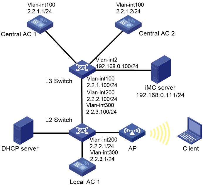
Network configuration
As shown in Figure 1, the AC hierarchy network contains two central ACs. The AP and client obtain an IP address from the DHCP server, and the IMC server acts as both the portal authentication server and RADIUS server. Configure the devices to meet the following requirements:
· The central ACs operate in master/backup mode and back up each other. Central AC 1 acts as the master central AC, and central AC 2 acts as the backup central AC
· The AP obtains the IP addresses of the central ACs from the DHCP server through DHCP Option 43. The AC rediscovery feature is configured on the central ACs. For the AP to associate with the local AC, enable the AC rediscovery feature in the view of the manual AP. In addition, configure the central ACs to add the IP address of the local AC to the CAPWAP Control IP Address message element in the discovery responses sent to the AP. The AP, central ACs, and the local AC are reachable to each other so that the AP can associate with a central AC when the local AC fails.
· Use direct portal authentication for wireless clients.
· Use the central ACs as the authenticator.
· Configure the AP to forward client data traffic.
Analysis
· Make sure the master and backup central ACs run the same version of software and have the same settings.
· For GigabitEthernet 1/0/1 to forward client data traffic in VLAN 300, edit the configuration file of the AP and upload the file to the central ACs.
· To avoid portal authentication failure caused by frequent portal client onboarding and offboarding, disable the Rule ARP entry feature for portal clients.
· For the RADIUS server to dynamically change client authorization information or forcibly disconnect a wireless client, enable the RADIUS session-control feature on the central ACs.
Restrictions and guidelines
· Central ACs on an AC hierarchy network do not support IRF.
· Use the actual serial ID of an AP to uniquely identify that AP.
· On the local AC, do not enable the auto AP feature. In addition, create a manual AP for the AP in local AC view on the central ACs for the central ACs to manage the AP.
· For dual-link central AC backup to operate correctly, configure the local AC and manual AP settings on both central ACs. Make sure the priority settings on the local AC, the master central AC, and the backup central AC are correctly configured so that the local AC can re-associate with the master central AC when the master central AC recovers.
Procedures
Editing the AP’s configuration file
# Edit the AP’s configuration file, name it apmap.txt and upload the configuration file to the AC.
System-view
vlan 300
interface gigabitethernet1/0/1
port link-type trunk
port trunk permit vlan 300
Configuring central AC 1
1. Configure interfaces on central AC 1:
# Create VLAN 100 and VLAN-interface 100, and assign an IP address to the VLAN interface. The central AC will use this IP address to establish a management tunnel with the local AC.
<Central-AC1> system-view
[Central-AC1] vlan 100
[Central-AC1-vlan100] quit
[Central-AC1] interface vlan-interface 100
[Central-AC1-Vlan-interface100] ip address 2.2.1.1 24
[Central-AC1-Vlan-interface100] quit
# Configure GigabitEthernet 1/0/1 (the port connected to the Layer 3 switch) as a trunk port, and assign the port to VLAN 100.
[Central-AC1] interface gigabitethernet 1/0/1
[Central-AC1-GigabitEthernet1/0/1] port link-type trunk
[Central-AC1-GigabitEthernet1/0/1] port trunk permit vlan 100
[Central-AC1-GigabitEthernet1/0/1] quit
2. Configure a local AC for central AC 1:
# Create local AC 3510 with model WX3510H and enter local AC view.
[Central-AC1] wlan local-ac name 3510 model WX3510H
# Specify the serial ID of the local AC.
[Central-AC1-wlan-local-ac-3510] serial-id 210235A1JNB165000120
# Set the priority to 7 for tunnel establishment to the local AC.
[Central-AC1-wlan-local-ac-3510] priority 7
# Enable master CAPWAP tunnel preemption.
[Central-AC1-wlan-local-ac-3510] wlan tunnel-preempt enable
[Central-AC1-wlan-local-ac-3510] quit
3. Configure portal authentication for clients:
¡ Configure a RADIUS scheme:
# Create a RADIUS scheme named imc and enter RADIUS scheme view.
[Central-AC1] radius scheme imc
# Specify the IP address of the primary RADIUS authentication server.
[Central-AC1-radius-imc] primary authentication 192.168.0.111
# Specify the IP address of the primary RADIUS accounting server.
[Central-AC1-radius-imc] primary accounting 192.168.0.111
# Set the shared key to 123456 in plaintext form for secure communication with the RADIUS authentication server.
[Central-AC1-radius-imc] key authentication simple 123456
# Set the shared key to 123456 in plaintext form for secure communication with the RADIUS accounting server.
[Central-AC1-radius-imc] key accounting simple 123456
# Configure the AC to remove the domain name from the usernames sent to the RADIUS servers.
[Central-AC1-radius-imc] user-name-format without-domain
# Specify IP address 2.2.1.1 as the source IP address for outgoing RADIUS packets.
[Central-AC1-radius-imc] nas-ip 2.2.1.1
[Central-AC1-radius-imc] quit
# Enable RADIUS session-control.
[Central-AC1] radius session-control enable
¡ Configure an authentication domain:
# Create ISP domain imc and enter its view.
[Central-AC1] domain imc
# Configure the ISP domain to use RADIUS scheme imc for portal user authentication, authorization, and accounting.
[Central-AC1-isp-imc] authentication lan-access radius-scheme imc
[Central-AC1-isp-imc] authorization lan-access radius-scheme imc
[Central-AC1-isp-imc] accounting lan-access radius-scheme imc
# Set the idle timeout period to 15 minutes for the users in the imc ISP domain.
[Central-AC1-isp-imc] authorization-attribute idle-cut 15 1024
[Central-AC1-isp-imc] quit
4. Configure a wireless service:
# Create a service template named st1 and enter its view.
[Central-AC1] wlan service-template st1
# Configure the SSID as service.
[Central-AC1-wlan-st-st1] ssid service
# Specify the AKM mode as PSK, and configure the preshared key as 12345678 in plain text.
[Central-AC1-wlan-st-st1] akm mode psk
[Central-AC1-wlan-st-st1] preshared-key pass-phrase simple 12345678
# Specify the cipher suite as CCMP and the security IE as RSN.
[Central-AC1-wlan-st-st1] cipher-suite ccmp
[Central-AC1-wlan-st-st1] security-ie rsn
# Configure the AP to forward client data traffic. (Skip this step if the client data traffic forwarder is the AP by default.)
[Central-AC1-wlan-st-st1] client forwarding-location ap
# Specify the central AC as the authenticator.
[Central-AC1-wlan-st-st1] client-security authentication-location central-ac
# Specify the authentication domain as imc for portal users.
[Central-AC1-wlan-st-st1] portal domain imc
# Enable the service template.
[Central-AC1-wlan-st-st1] service-template enable
[Central-AC1-wlan-st-st1] quit
5. Configure portal authentication:
# Create a portal authentication server named newpt, specify IP address 192.168.0.111 as the IP address of the authentication server, and specify 50100 as the portal service port number.
[Central-AC1] portal server newpt
[Central-AC1-portal-server-newpt] ip 192.168.0.111 key simple radius
[Central-AC1-portal-server-newpt] port 50100
# Specify CMCC as the type of portal authentication server newpt.
[Central-AC1-portal-server-newpt] server-type cmcc
[Central-AC1-portal-server-newpt] quit
# Create a portal Web server named newpt and specify http://192.168.0.111:8080/portal as the URL of the server.
[Central-AC1] portal web-server newpt
[Central-AC1-portal-websvr-newpt] url http://192.168.0.111:8080/portal
# Add parameters ssid, wlanuserip, and wlanacname to the URL of portal Web server newpt. Specify the AP's SSID, the IP address of the client, and the AC's name as the values for the parameters, respectively. (The parameters are required to be carried in the URL of a portal Web server of the CMCC type.)
[Central-AC1-portal-websvr-newpt] url-parameter ssid ssid
[Central-AC1-portal-websvr-newpt] url-parameter wlanuserip source-address
[Central-AC1-portal-websvr-newpt] url-parameter wlanacname value Central-AC1
# Specify CMCC as the type of portal Web server newpt.
[Central-AC1-portal-websvr-newpt] server-type cmcc
[Central-AC1-portal-websvr-newpt] quit
# Configure a destination-based portal-free rule numbered 0 to permit traffic destined for IP address 192.168.0.111 (the portal Web server).
[Central-AC1] portal free-rule 0 destination ip 192.168.0.111 24
# Configure two portal-free rules, allowing access to the DNS server without portal authentication.
[Central-AC1] portal free-rule 1 destination ip any udp 53
[Central-AC1] portal free-rule 2 destination ip any tcp 53
# Enable portal roaming.
[Central-AC1] portal roaming enable
# Disable the Rule ARP entry feature for portal clients.
[Central-AC1] undo portal refresh arp enable
# Enable direct IPv4 portal authentication on service template st1.
[Central-AC1] wlan service-template st1
[Central-AC1-wlan-st-st1] portal enable method direct
# Specify IPv4 portal Web server newpt on service template st1 for portal authentication.
[Central-AC1-wlan-st-st1] portal apply web-server newpt
# On service template st1, configure the BAS-IP attribute as 2.2.1.1 for portal packets sent to the portal authentication server.
[Central-AC1-wlan-st-st1] portal bas-ip 2.2.1.1
[Central-AC1-wlan-st-st1] quit
6. Configure the AP:
|
|
NOTE: In large-scale networks, configure AP groups instead of single APs as a best practice. |
# Create a manual AP named ap1, and specify the AP model and serial ID.
[Central-AC1] wlan ap ap1 model WA6320
[Central-AC1-wlan-ap-ap1] serial-id 219801A28N819CE0002T
[Central-AC1-wlan-ap-ap1] quit
# Create AP group group1.
[Central-AC1] wlan ap-group group1
# Enable AC rediscovery.
[Central-AC1-wlan-ap-group-group1] control-address enable
# Specify a local AC.
[Central-AC1-wlan-ap-group-group1] control-address ip 2.2.2.1
# Specify a backup AC for the central AC.
[Central-AC1-wlan-ap-group-group1] backup-ac ip 2.2.1.2
# Enable automatic switch-back after a local-central AC switchover.
[Central-AC1-wlan-ap-group-group1] switch-back enable
# Add AP ap1 to AP group group1.
[Central-AC1-wlan-ap-group-group1] ap ap1
# Deploy a configuration file to the AP.
[Central-AC1-wlan-ap-group-group1] ap-model WA6320
[Central-AC1-wlan-ap-group-group1-ap-model-WA6320] map-configuration cfa0:/apmap.txt
# Bind service template st1 to radio 1 in AP group group1.
[Central-AC1-wlan-ap-group-group1-ap-model-WA6320] radio 1
[Central-AC1-wlan-ap-group-group1-ap-model-WA6320-radio-1] service-template st1 vlan 300
# Enable radio 1.
[Central-AC1-wlan-ap-group-group1-ap-model-WA6320-radio-1] radio enable
[Central-AC1-wlan-ap-group-group1-ap-model-WA6320-radio-1] quit
[Central-AC1-wlan-ap-group-group1-ap-model-WA6320] quit
[Central-AC1-wlan-ap-group-group1] quit
7. Configure a static route:
# Configure a static route, whose next hop address is 2.2.1.100, IP address of the Layer 3 switch.
[Central-AC1] ip route-static 0.0.0.0 24 2.2.1.100
Configure central AC 2
1. Configure interfaces on central AC 2:
# Create VLAN 100 and VLAN-interface 100, and assign an IP address to the VLAN interface. The central AC will use this IP address to establish a management tunnel with the local AC.
<Central-AC2> system-view
[Central-AC2] vlan 100
[Central-AC2-vlan100] quit
[Central-AC2] interface vlan-interface 100
[Central-AC2-Vlan-interface100] ip address 2.2.1.2 24
[Central-AC2-Vlan-interface100] quit
# Configure GigabitEthernet 1/0/1 (the port connected to the Layer 3 switch) as a trunk port, and assign the port to VLAN 100.
[Central-AC2] interface gigabitethernet 1/0/1
[Central-AC2-GigabitEthernet1/0/1] port link-type trunk
[Central-AC2-GigabitEthernet1/0/1] port trunk permit vlan 100
[Central-AC2-GigabitEthernet1/0/1] quit
2. Configure a local AC for central AC 2:
# Create local AC 3510 with model WX3510H and enter local AC view.
[Central-AC2] wlan local-ac name 3510 model WX3510H
# Specify the serial ID of the local AC.
[Central-AC2-wlan-local-ac-3510] serial-id 210235A1JNB165000120
# Set the priority to 6 for tunnel establishment to the local AC.
[Central-AC2-wlan-local-ac-3510] priority 6
# Enable master CAPWAP tunnel preemption.
[Central-AC2-wlan-local-ac-3510] wlan tunnel-preempt enable
[Central-AC2-wlan-local-ac-3510] quit
3. Configure portal authentication for clients:
¡ Configure a RADIUS scheme:
# Create a RADIUS scheme named imc and enter RADIUS scheme view.
[Central-AC2] radius scheme imc
# Specify the IP address of the primary RADIUS authentication server.
[Central-AC2-radius-imc] primary authentication 192.168.0.111
# Specify the IP address of the primary RADIUS accounting server.
[Central-AC2-radius-imc] primary accounting 192.168.0.111
# Set the shared key to 123456 in plaintext form for secure communication with the RADIUS authentication server.
[Central-AC2-radius-imc] key authentication simple 123456
# Set the shared key to 123456 in plaintext form for secure communication with the RADIUS accounting server.
[Central-AC2-radius-imc] key accounting simple 123456
# Configure the AC to remove the domain name from the usernames sent to the RADIUS servers.
[Central-AC2-radius-imc] user-name-format without-domain
# Specify IP address 2.2.1.2 as the source IP address for outgoing RADIUS packets.
[Central-AC2-radius-imc] nas-ip 2.2.1.2
[Central-AC2-radius-imc] quit
# Enable RADIUS session-control.
[Central-AC2] radius session-control enable
¡ Configure an authentication domain:
# Create ISP domain imc and enter its view.
[Central-AC2] domain imc
# Configure the ISP domain to use RADIUS scheme imc for portal user authentication, authorization, and accounting.
[Central-AC2-isp-imc] authentication lan-access radius-scheme imc
[Central-AC2-isp-imc] authorization lan-access radius-scheme imc
[Central-AC2-isp-imc] accounting lan-access radius-scheme imc
# Set the idle timeout period to 15 minutes and the minimum traffic that must be generated in the idle timeout period to 1024 bytes for the users in the imc ISP domain.
[Central-AC2-isp-imc] authorization-attribute idle-cut 15 1024
[Central-AC2-isp-imc] quit
4. Configure a wireless service:
# Create a service template named st1 and enter its view.
[Central-AC2] wlan service-template st1
# Configure the SSID as service.
[Central-AC2-wlan-st-st1] ssid service
# Specify the AKM mode as PSK, and configure the preshared key as 12345678 in plain text.
[Central-AC2-wlan-st-st1] akm mode psk
[Central-AC2-wlan-st-st1] preshared-key pass-phrase simple 12345678
# Specify the cipher suite as CCMP and the security IE as RSN.
[Central-AC2-wlan-st-st1] cipher-suite ccmp
[Central-AC2-wlan-st-st1] security-ie rsn
# Configure the AP to forward client data traffic. (Skip this step if the client data traffic forwarder is the AP by default.)
[Central-AC2-wlan-st-st1] client forwarding-location ap
# Specify the central AC as the authenticator.
[Central-AC2-wlan-st-st1] client-security authentication-location central-ac
# Specify the authentication domain as imc for portal users.
[Central-AC2-wlan-st-st1] portal domain imc
# Enable the service template.
[Central-AC2-wlan-st-st1] service-template enable
[Central-AC2-wlan-st-st1] quit
5. Configure portal authentication:
# Create a portal authentication server named newpt, specify IP address 192.168.0.111 as the IP address of the authentication server, and specify 50100 as the portal service port number.
[Central-AC2] portal server newpt
[Central-AC2-portal-server-newpt] ip 192.168.0.111 key simple radius
[Central-AC2-portal-server-newpt] port 50100
# Specify CMCC as the type of portal authentication server newpt.
[Central-AC2-portal-server-newpt] server-type cmcc
[Central-AC2-portal-server-newpt] quit
# Create a portal Web server named newpt and specify http://192.168.0.111:8080/portal as the URL of the server.
[Central-AC2] portal web-server newpt
[Central-AC2-portal-websvr-newpt] url http://192.168.0.111:8080/portal
# Add parameters ssid, wlanuserip, and wlanacname to the URL of portal Web server newpt. Specify the AP's SSID, the IP address of the client, and the AC's name as the values for the parameters, respectively. (The parameters are required to be carried in the URL of a portal Web server of the CMCC type.)
[Central-AC2-portal-websvr-newpt] url-parameter ssid ssid
[Central-AC2-portal-websvr-newpt] url-parameter wlanuserip source-address
[Central-AC2-portal-websvr-newpt] url-parameter wlanacname value Central-AC2
# Specify CMCC as the type of portal Web server newpt.
[Central-AC2-portal-websvr-newpt] server-type cmcc
[Central-AC2-portal-websvr-newpt] quit
# Configure a destination-based portal-free rule numbered 0 to permit traffic destined for IP address 192.168.0.111 (the portal Web server).
[Central-AC2] portal free-rule 0 destination ip 192.168.0.111 24
# Configure two portal-free rules, allowing access to the DNS server without portal authentication.
[Central-AC2] portal free-rule 1 destination ip any udp 53
[Central-AC2] portal free-rule 2 destination ip any tcp 53
# Enable portal roaming.
[Central-AC2] portal roaming enable
# Disable the Rule ARP entry feature for portal clients.
[Central-AC2] undo portal refresh arp enable
# Enable direct IPv4 portal authentication on service template st1.
[Central-AC2] wlan service-template st1
[Central-AC2-wlan-st-st1] portal enable method direct
# Specify IPv4 portal Web server newpt on service template st1 for portal authentication.
[Central-AC2-wlan-st-st1] portal apply web-server newpt
# On service template st1, configure the BAS-IP attribute as 2.2.1.2 for portal packets sent to the portal authentication server.
[Central-AC2-wlan-st-st1] portal bas-ip 2.2.1.2
[Central-AC2-wlan-st-st1] quit
6. Configure the AP:
|
|
NOTE: In large-scale networks, configure AP groups instead of single APs as a best practice. |
# Create a manual AP named ap1, and specify the AP model and serial ID.
[Central-AC2] wlan ap ap1 model WA6320
[Central-AC2-wlan-ap-ap1] serial-id 219801A28N819CE0002T
[Central-AC2-wlan-ap-ap1] quit
# Create AP group group1.
[Central-AC2] wlan ap-group group1
# Enable AC rediscovery.
[Central-AC2-wlan-ap-group-group1] control-address enable
# Specify the local AC.
[Central-AC2-wlan-ap-group-group1] control-address ip 2.2.2.1
# Specify central AC 1 as the backup AC for central AC 2.
[Central-AC2-wlan-ap-group-group1] backup-ac ip 2.2.1.1
# Enable automatic switch-back after a local-central AC switchover.
[Central-AC2-wlan-ap-group-group1] switch-back enable
# Add AP ap1 to AP group group1.
[Central-AC2-wlan-ap-group-group1] ap ap1
# Deploy a configuration file to the AP.
[Central-AC2-wlan-ap-group-group1] ap-model WA6320
[Central-AC2-wlan-ap-group-group1-ap-model-WA6320] map-configuration cfa0:/apmap.txt
# Bind service template st1 to radio 1 in AP group group1.
[Central-AC2-wlan-ap-group-group1-ap-model-WA6320] radio 1
[Central-AC2-wlan-ap-group-group1-ap-model-WA6320-radio-1] service-template st1 vlan 300
# Enable radio 1.
[Central-AC2-wlan-ap-group-group1-ap-model-WA6320-radio-1] radio enable
[Central-AC2-wlan-ap-group-group1-ap-model-WA6320-radio-1] quit
[Central-AC2-wlan-ap-group-group1-ap-model-WA6320] quit
[Central-AC2-wlan-ap-group-group1] quit
7. Configure a static route:
# Configure a static route, whose next hop address is 2.2.1.100, IP address of the Layer 3 switch.
[Central-AC2] ip route-static 0.0.0.0 0 24 2.2.1.100
Configuring the local AC
1. Configure the local AC feature:
# Enable the local AC feature.
<Local AC> system-view
[Local AC] wlan local-ac enable
# Specify central ACs for the local AC.
[Local AC] wlan central-ac ip 2.2.1.1
[Local AC] wlan central-ac ip 2.2.1.2
# Configure the local AC to use VLAN 100 to establish a tunnel with the central ACs.
[Local AC] wlan local-ac capwap source-vlan 100
2. Configure interfaces:
# Create VLAN 100, create VLAN-interface 100, and assign an IP address to the VLAN interface. The local AC will use this IP address to establish CAPWAP tunnels with the central ACs.
[Local AC] vlan 100
[Local AC-vlan100] quit
[Local AC] interface Vlan-interface100
[Local AC-Vlan-interface100] ip address 2.2.1.10 255.255.255.0
[Local AC-Vlan-interface100] quit
# Create VLAN 200, create VLAN-interface 200, and assign an IP address to the VLAN interface. The local AC assigns VLAN 200 to an AP when the AP comes online.
[Local AC] vlan 200
[Local AC-vlan200] quit
[Local AC] interface Vlan-interface200
[Local AC-Vlan-interface200] ip address 2.2.2.1 255.255.255.0
[Local AC-Vlan-interface200] quit
# Create VLAN 300, create VLAN-interface 300, and assign an IP address to the VLAN interface. The local AC assigns this VLAN to a wireless client when the client comes online.
[Local AC] vlan 300
[Local AC-vlan300] quit
[Local AC] interface Vlan-interface300
[Local AC-Vlan-interface300] ip address 2.2.3.1 255.255.255.0
[Local AC-Vlan-interface300] quit
# Configure GigabitEthernet 1/0/1 (the port connected to the Layer 2 switch) as a trunk port, and assign the port to VLAN 100 and VLAN 200.
[Local AC] interface gigabitEthernet 1/0/1
[Local AC-GigabitEthernet1/0/1] port link-type trunk
[Local AC-GigabitEthernet1/0/1] port trunk permit vlan 100 200
[Local AC-GigabitEthernet1/0/1] quit
Configuring the Layer 3 switch
# Create VLAN 100, create VLAN-interface 100, and assign an IP address to the VLAN interface. The switch will use this VLAN to forward data and control packets between the central ACs and the local AC.
<L3 switch> system-view
[L3 switch] vlan 100
[L3 switch-vlan100] quit
[L3 switch] interface vlan-interface 100
[L3 switch-Vlan-interface100] ip address 2.2.1.100 255.255.255.0
[L3 switch-Vlan-interface100] quit
# Create VLAN 200, create VLAN-interface 200, and assign an IP address to the VLAN interface. The switch will use this VLAN to forward CAPWAP tunnel packets between the local AC and the AP.
[L3 switch] vlan 200
[L3 switch-vlan200] quit
[L3 switch] interface vlan-interface 200
[L3 switch-Vlan-interface200] ip address 2.2.2.100 255.255.255.0
[L3 switch-Vlan-interface200] quit
# Create VLAN 300 for wireless clients, create VLAN-interface 300, and assign an IP address to the VLAN interface.
[L3 switch] vlan 300
[L3 switch-vlan300] quit
[L3 switch] interface vlan-interface 300
[L3 switch-Vlan-interface300] ip address 2.2.3.100 255.255.255.0
[L3 switch-Vlan-interface300] quit
# Create VLAN 2, create VLAN-interface 2, and assign an IP address to the VLAN interface. The switch will use this VLAN to connect to the IMC server.
[L3 switch] vlan 2
[L3 switch-vlan2] quit
[L3 switch] interface vlan-interface 2
[L3 switch-Vlan-interface2] ip address 192.168.0.100 255.255.255.0
[L3 switch-Vlan-interface2] quit
Assign the port that connects the Layer 3 switch to the IMC server to VLAN 2. (Details not shown.)
# Configure GigabitEthernet 1/0/1 that connects the Layer 3 switch to central AC 1 as a trunk port, and assign the port to VLAN 100.
[L3 switch] interface gigabitethernet 1/0/1
[L3 switch-GigabitEthernet1/0/1] port link-type trunk
[L3 switch-GigabitEthernet1/0/1] port trunk permit vlan 100
[L3 switch-GigabitEthernet1/0/1] quit
# Configure GigabitEthernet 1/0/3 that connects the Layer 3 switch to central AC 2 as a trunk port, and assign the port to VLAN 100.
[L3 switch] interface gigabitEthernet 1/0/3
[L3 switch-GigabitEthernet1/0/3] port link-type trunk
[L3 switch-GigabitEthernet1/0/3] port trunk permit vlan 100
[L3 switch-GigabitEthernet1/0/3] quit
# Configure GigabitEthernet 1/0/2 that connects the Layer 3 switch to the Layer 2 switch as a trunk port, and assign the port to VLAN 200 and VLAN 300.
[L3 switch] interface gigabitethernet 1/0/2
[L3 switch-GigabitEthernet1/0/2] port link-type trunk
[L3 switch-GigabitEthernet1/0/2] port trunk permit vlan 200 300
[L3 switch-GigabitEthernet1/0/2] quit
Configuring the Layer 2 switch
# Create VLAN 100, VLAN 200, and VLAN 300.
<L2 switch> system-view
[L2 switch] vlan 100
[L2 switch-vlan100] quit
[L2 switch] vlan 200
[L2 switch-vlan200] quit
[L2 switch] vlan 300
[L2 switch-vlan300] quit
# Configure GigabitEthernet 1/0/1 that connects the Layer 2 switch to the Layer 3 switch as a trunk port, and assign the port to VLAN 100, VLAN 200, and VLAN 300.
[L2 switch] interface gigabitethernet 1/0/1
[L2 switch-GigabitEthernet1/0/1] port link-type trunk
[L2 switch-GigabitEthernet1/0/1] port trunk permit vlan 100 200 300
[L2 switch-GigabitEthernet1/0/1] quit
# Configure GigabitEthernet 1/0/3 that connects the Layer 2 switch to the local AC as a trunk port, and assign the port to VLAN 100 and VLAN 200.
[L2 switch] interface gigabitEthernet 1/0/3
[L2 switch-GigabitEthernet1/0/3] port link-type trunk
[L2 switch-GigabitEthernet1/0/3] port trunk permit vlan 100 200
[L2 switch-GigabitEthernet1/0/3] quit
# Configure GigabitEthernet 1/0/4 that connects the Layer 2 switch to the DHCP server as a trunk port, and assign the port to VLAN 200 and VLAN 300.
[L2 switch] interface gigabitEthernet 1/0/4
[L2 switch-GigabitEthernet1/0/4] port link-type trunk
[L2 switch-GigabitEthernet1/0/4] port trunk permit vlan 200 300
[L2 switch-GigabitEthernet1/0/4] quit
# Configure GigabitEthernet 1/0/2 that connects the Layer 2 switch to the AP as a trunk port, remove the port from VLAN 1, assign the port to VLAN 200 and VLAN 300, and enable PoE on the port.
[L2 switch] interface gigabitethernet 1/0/2
[L2 switch-GigabitEthernet1/0/2] port link-type trunk
[L2 switch-GigabitEthernet1/0/2] undo port trunk permit vlan 1
[L2 switch-GigabitEthernet1/0/2] port trunk pvid vlan 200
[L2 switch-GigabitEthernet1/0/2] port trunk permit vlan 200 300
[L2 switch-GigabitEthernet1/0/2] poe enable
[L2 switch-GigabitEthernet1/0/2] quit
Configuring the DHCP server
# Configure GigabitEthernet 1/0/1 that connects the DHCP server to the Layer 2 switch as a trunk port, and assign the port to VLAN 200 and VLAN 300.
<DHCP Server> system-view
[DHCP Server] interface gigabitethernet 1/0/1
[DHCP Server-GigabitEthernet1/0/1] port link-type trunk
[DHCP Server-GigabitEthernet1/0/1] port trunk permit vlan 200 300
[DHCP Server-GigabitEthernet1/0/1] quit
# Create VLAN 200, create VLAN-interface 200, and assign an IP address to the VLAN interface.
[DHCP Server] vlan 200
[DHCP Server-vlan200] quit
[DHCP Server] interface vlan-interface 200
[DHCP Server-Vlan-interface200] ip address 2.2.2.200 255.255.255.0
[DHCP Server-Vlan-interface100] quit
# Create VLAN 300, create VLAN-interface 300, and assign an IP address to the VLAN interface.
[DHCP Server] vlan 300
[DHCP Server-vlan300] quit
[DHCP Server] interface vlan-interface 300
[Dhcp Server-Vlan-interface300] ip address 2.2.3.200 255.255.255.0
[DHCP Server-Vlan-interface300] quit
# Enable the DHCP service.
[DHCP Server] dhcp enable
# Configure DHCP address pool vlan200. In the address pool, specify 2.2.2.100 (the IP address of VLAN-interface 200 on the Layer 3 switch) as the gateway IP address and 2.2.2.0/24 as the subnet for dynamic allocation, and then exclude 2.2.2.100 and 2.2.2.1 from dynamic allocation.
[DHCP Server] dhcp server ip-pool vlan200
[DHCP Server-dhcp-pool-vlan200] gateway-list 2.2.2.100
[DHCP Server-dhcp-pool-vlan200] network 2.2.2.0 mask 255.255.255.0
[DHCP Server-dhcp-pool-vlan200] forbidden-ip 2.2.2.100 2.2.2.1
# Configure Option 43 to specify the IP addresses of the central ACs in address pool vlan200. The right-most bytes 0202010102020102 (2.2.1.1 and 2.2.1.2) represent the IP addresses of central AC 1 and central AC 2.
[DHCP Server-dhcp-pool-vlan200] option 43 hex 800b0000010202010102020102
[DHCP Server-dhcp-pool-vlan200] quit
[DHCP Server-dhcp-pool-vlan200] quit
# Configure DHCP address pool vlan300. In the address pool, specify 2.2.3.100 (the IP address of VLAN-interface 300 on the Layer 3 switch) as the gateway IP address, 2.2.3.0/24 as the subnet for dynamic allocation, and 8.8.8.8 as the DNS server address, and then exclude 2.2.3.100 and 2.2.3.1 from dynamic allocation.
[DHCP Server] dhcp server ip-pool vlan300
[DHCP Server-dhcp-pool-vlan300] gateway-list 2.2.3.100
[DHCP Server-dhcp-pool-vlan300] network 2.2.3.0 mask 255.255.255.0
[DHCP Server-dhcp-pool-vlan300] dns-list 8.8.8.8
[DHCP Server-dhcp-pool-vlan300] forbidden-ip 2.2.3.100 2.2.3.1
Configuring the RADIUS server
In this example, the RADIUS server runs IMC PLAT 7.1 (E0303p13), IMC EIA 7.1 (F0302p08), and IMC EIP 7.1 (F0302p08).
The IMC server configuration is the same for central AC 1 and central AC 2, except for the AC IP address. This section configures central AC 1 as an example. Refer to central AC 1 configuration when you configure central AC 2 and remember to change the IP address setting for central AC 2.
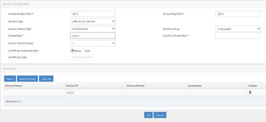
1. Add central AC 1 as an access device.
a. Log in to IMC and click the User tab.
b. From the navigation pane, select User Access Policy > Access Device Management > Access Device.
c. Click Add.
d. In the Device List area, click Add Manually to open the Add Access Device Manually page. Enter 2.2.1.1 in the Start IP field and then click OK.
e. In the Access Configuration area, set the shared key to 123456, which must be the same as that configured on the AC.
f. Use the default settings for other parameters.
g. Click OK.
Figure 2 Adding central AC 1 as an access device
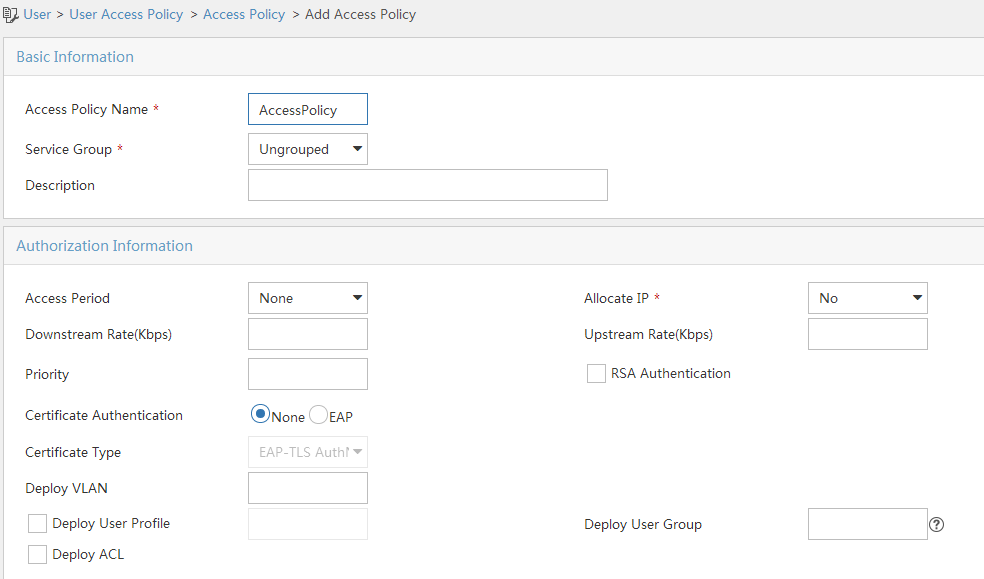
2. Add an access policy.
a. From the navigation pane, select User Access Policy > Access Policy.
b. Click Add.
c. Enter the access policy name.
d. Select the Ungrouped service group.
e. Use the default settings for other parameters.
Figure 3 Adding an access policy
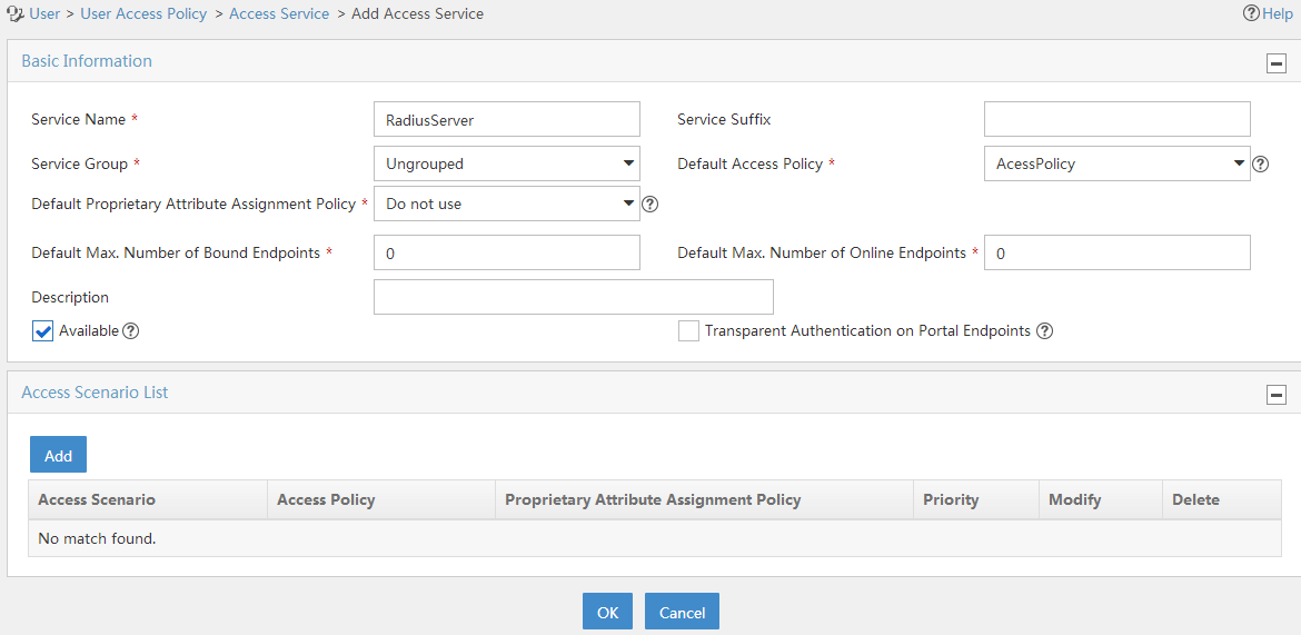
3. Add an access service.
a. From the navigation pane, select User Access Policy > Access Service.
b. Click Add.
c. Enter the service name.
d. Select AccessPolicy.
e. Use the default settings for other parameters.
f. Click OK.
Figure 4 Adding an access service
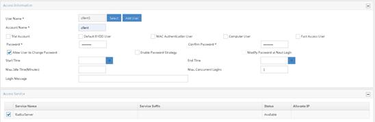
4. Add an access user.
a. From the navigation pane, select Access User > All Access Users.
b. Click Add.
c. Select an existing access user or click Add User to add a new access user.
d. In the Access Service area, select RadiusServer from the list.
e. Set the password.
f. Use the default settings for other parameters.
g. Click OK.
Figure 5 Adding an access user
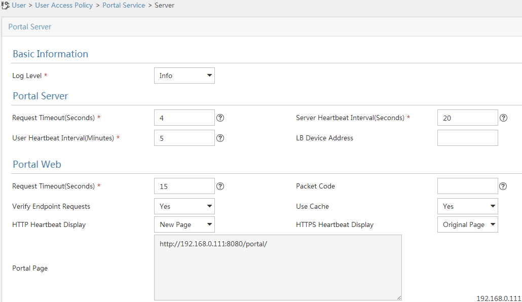
Configuring the portal server
1. Configure the portal authentication service:
a. From the navigation pane, select User Access Policy > Portal Service > Server.
b. Configure the portal server parameters as needed.
This example uses the default settings.
c. Click OK.
Figure 6 Configuring the portal server
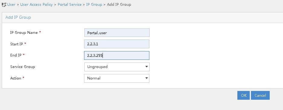
2. Configure an IP address group:
a. From the navigation pane, select User Access Policy > Portal Service > IP Group.
b. Click Add.
c. Enter the IP group name.
d. Enter the start IP address and end IP address of the IP group.
Make sure the client IP address is in the IP group.
e. Select a service group.
This example uses the default group Ungrouped.
f. Select Normal from the Action list.
g. Click OK.
Figure 7 Adding an IP address group
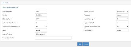
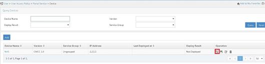
3. Add a portal device:
a. From the navigation pane, select User Access Policy > Portal Service > Device.
b. Click Add.
c. Enter the device name.
d. Select CMCC 1.0 for Version.
e. Enter the IP address of the AC's interface connected to the client.
f. Set whether to support the portal server heartbeat and user heartbeat functions.
In this example, select No for both Support Server Heartbeat and Support User Heartbeat.
g. Enter the key, which must be the same as that configured on the AC.
h. Select Directly Connected for Access Method.
i. Use the default settings for other parameters.
j. Click OK.
Figure 8 Adding a portal device
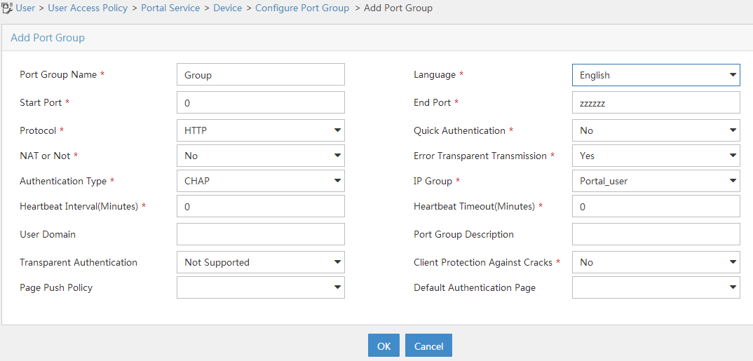
4. Associate the portal device with the IP address group:
a. Click the Port Group icon in the Operation field of device NAS.
b. Click Add.
c. Enter the port group name.
d. Select the configured IP address group.
The IP address used by the user to access the network must be within this IP address group.
e. Use the default settings for other parameters.
f. Click OK.
Verifying the configuration
# Use the configured username and password to perform portal authentication through a Web browser on the client. Before passing portal authentication, the user can access only the authentication page http://192.168.0.111:8080/portal. All Web requests from the user will be redirected to the authentication page. After passing portal authentication, the user can access other network resources.
# Display information about all portal users.
[Central-AC1] display portal user all
Total portal users: 1
Username: client
AP name: ap1
Radio ID: 1
SSID: service
Portal server: newpt
State: Online
VPN instance: N/A
MAC IP VLAN Interface
0021-6330-0933 2.2.3.143 300 WLAN-BSS1/0/4
Authorization information:
DHCP IP pool: vlan300
User profile: N/A
Session group profile: N/A
ACL number: N/A
Inbound CAR: N/A
Outbound CAR: N/A
Configuration files
· Layer 3 switch:
#
Vlan 2
#
vlan 100
#
vlan 200
#
vlan 300
#
interface Vlan-interface2
ip address 192.168.0.100 255.255.255.0
#
interface Vlan-interface100
ip address 2.2.1.100 255.255.255.0
#
interface Vlan-interface200
ip address 2.2.2.100 255.255.255.0
#
interface Vlan-interface300
ip address 2.2.3.100 255.255.255.0
#
interface GigabitEthernet1/0/1
port link-type trunk
port trunk permit vlan 1 100
#
interface GigabitEthernet1/0/2
port link-type trunk
port trunk permit vlan 1 200 300
#
interface GigabitEthernet1/0/3
port link-type trunk
port trunk permit vlan 1 100
#
· Central AC 1:
#
vlan 100
#
wlan service-template st1
ssid service
client forwarding-location ap
client-security authentication-location central-ac
akm mode psk
preshared-key pass-phrase cipher $c$3$oLf6pOZ6bxrf25nodjOJKYEfnZ6g6ErccHyQ
cipher-suite ccmp
security-ie rsn
portal enable method direct
portal domain imc
portal bas-ip 2.2.1.1
portal apply web-server newpt
service-template enable
#
interface Vlan-interface100
ip address 2.2.1.1 255.255.255.0
#
interface gigabitethernet 1/0/1
port link-type trunk
port trunk permit vlan 1 100
#
ip route-static 0.0.0.0 24 2.2.1.100
#
radius session-control enable
#
radius scheme imc
primary authentication 192.168.0.111
primary accounting 192.168.0.111
key authentication cipher $c$3$inPh3pDjv+jZhbhAmYd7sPQMF8bJX0VmvA==
key accounting cipher $c$3$lZDbA3Qutvq0fWYBaI4ESvGfDW2uBOfF1A==
user-name-format without-domain
nas-ip 2.2.1.1
#
domain imc
authorization-attribute idle-cut 15 1024
authentication lan-access radius-scheme imc
authorization lan-access radius-scheme imc
accounting lan-access radius-scheme imc
#
portal free-rule 0 destination ip 192.168.0.0 255.255.255.0
portal free-rule 1 destination ip any udp 53
portal free-rule 2 destination ip any tcp 53
#
portal web-server newpt
url http://192.168.0.111:8080/portal
server-type cmcc
url-parameter ssid ssid
url-parameter wlanacname value Central-AC1
url-parameter wlanuserip source-address
#
portal server newpt
ip 192.168.0.111 key cipher $c$3$8MR9sJDNDI9wpjox6qMBHOLQcTVlY7f9
server-type cmcc
#
wlan ap-group group1
backup-ac ip 2.2.1.2
control-address enable
control-address ip 2.2.2.1
switch-back enable
ap ap1
ap-model WA6320
map-configuration cfa0:/map.txt
radio 1
radio enable
service-template st1 vlan 300
radio 2
#
wlan ap ap1 model WA6320
serial-id 219801A28N819CE0002T
#
wlan local-ac name 3510 model WX3510H
serial-id 210235A1JNB165000120
priority 7
wlan tunnel-preempt enable
#
· Central AC 2:
#
vlan 100
#
wlan service-template st1
ssid service
client forwarding-location ap
client-security authentication-location central-ac
akm mode psk
preshared-key pass-phrase cipher $c$3$oLf6pOZ6bxrf25nodjOJKYEfnZ6g6ErccHyQ
cipher-suite ccmp
security-ie rsn
portal enable method direct
portal domain imc
portal bas-ip 2.2.1.2
portal apply web-server newpt
service-template enable
#
interface Vlan-interface100
ip address 2.2.1.2 255.255.255.0
#
interface gigabitethernet 1/0/1
port link-type trunk
port trunk permit vlan 1 100
#
ip route-static 0.0.0.0 24 2.2.1.100
#
radius session-control enable
#
radius scheme imc
primary authentication 192.168.0.111
primary accounting 192.168.0.111
key authentication cipher $c$3$inPh3pDjv+jZhbhAmYd7sPQMF8bJX0VmvA==
key accounting cipher $c$3$lZDbA3Qutvq0fWYBaI4ESvGfDW2uBOfF1A==
user-name-format without-domain
nas-ip 2.2.1.2
#
domain imc
authorization-attribute idle-cut 15 1024
authentication lan-access radius-scheme imc
authorization lan-access radius-scheme imc
accounting lan-access radius-scheme imc
#
portal free-rule 0 destination ip 192.168.0.0 255.255.255.0
portal free-rule 1 destination ip any udp 53
portal free-rule 2 destination ip any tcp 53
#
portal web-server newpt
url http://192.168.0.111:8080/portal
server-type cmcc
url-parameter ssid ssid
url-parameter wlanacname value Central-AC2
url-parameter wlanuserip source-address
#
portal server newpt
ip 192.168.0.111 key cipher $c$3$8MR9sJDNDI9wpjox6qMBHOLQcTVlY7f9
server-type cmcc
#
wlan ap-group group1
backup-ac ip 2.2.1.1
control-address enable
control-address ip 2.2.2.1
switch-back enable
ap ap1
ap-model WA6320
map-configuration cfa0:/map.txt
radio 1
radio enable
service-template st1 vlan 300
radio 2
#
wlan ap ap1 model WA6320
serial-id 219801A28N819CE0002T
#
wlan local-ac name 3510 model WX3510H
serial-id 210235A1JNB165000120
priority 6
wlan tunnel-preempt enable
#
· Layer 2 switch:
#
vlan 100
#
vlan 200
#
vlan 300
#
interface GigabitEthernet1/0/1
port link-type trunk
port trunk permit vlan 1 100 200 300
#
interface GigabitEthernet1/0/2
port link-type trunk
undo port trunk permit vlan 1
port trunk permit vlan 200 300
port trunk pvid vlan 200
poe enable
#
interface GigabitEthernet1/0/3
port link-type trunk
port trunk permit vlan 1 100 200
#
interface GigabitEthernet1/0/4
port link-type trunk
port trunk permit vlan 1 200 300
#
· DHCP server:
#
dhcp enable
#
vlan 200
#
vlan 300
#
dhcp server ip-pool vlan200
gateway-list 2.2.2.100
network 2.2.2.0 mask 255.255.255.0
forbidden-ip 2.2.2.1
forbidden-ip 2.2.2.100
option 43 hex 800b0000010202010102020102
#
dhcp server ip-pool vlan300
gateway-list 2.2.3.100
network 2.2.3.0 mask 255.255.255.0
dns-list 8.8.8.8
forbidden-ip 2.2.3.1
forbidden-ip 2.2.3.100
#
interface Vlan-interface200
ip address 2.2.2.200 255.255.255.0
#
interface Vlan-interface300
ip address 2.2.3.200 255.255.255.0
#
interface GigabitEthernet1/0/1
port link-type trunk
port trunk permit vlan 1 200 300
#
· Local AC:
#
vlan 100
#
vlan 200
#
vlan 300
#
interface Vlan-interface100
ip address 2.2.1.10 255.255.255.0
#
interface Vlan-interface200
ip address 2.2.2.1 255.255.255.0
#
interface Vlan-interface300
ip address 2.2.3.1 255.255.255.0
#
interface GigabitEthernet1/0/1
port link-type trunk
port trunk permit vlan 1 100 200
#
wlan local-ac enable
#
wlan local-ac capwap source-vlan 100
#
wlan central-ac ip 2.2.1.1
wlan central-ac ip 2.2.1.2
#
Related documentation
· High Availability Command Reference in H3C Access Controllers Command References
· High Availability Configuration Guide in H3C Access Controllers Configuration Guides
· User Access and Authentication Command Reference in H3C Access Controllers Command References
· User Access and Authentication Configuration Guide in H3C Access Controllers Configuration Guides
· WLAN Access Command Reference in H3C Access Controllers Command References
· WLAN Access Configuration Guide in H3C Access Controllers Configuration Guides
