- Table of Contents
-
- 04-Comware 7 CLI-based configuration examples (AC+fit AP deployment)
- 01-HTTPS Login Configuration Examples
- 02-SSH Configuration Examples
- 03-License Management Configuration Examples
- 04-AP Association with the AC at Layer 2 Configuration Examples
- 05-AP Association with the AC at Layer 2 (IPv6) Configuration Examples
- 06-Auto AP Configuration Examples
- 07-AP Association with the AC at Layer 3 Configuration Examples
- 08-AP Association with the AC at Layer 3 (IPv6) Configuration Examples
- 09-WEP Encryption Configuration Examples
- 100-Static Blacklist Configuration Examples
- 101-Client Quantity Control Configuration Examples
- 102-AP License Synchronization Configuration Examples
- 103-BLE Module iBeacon Transmission Configuration Examples
- 104-Medical RFID Tag Management Configuration Examples
- 105-iBeacon Management Configuration Examples
- 106-Mesh Link Establishment Between Fit APs Configuration Examples
- 107-Mesh Link Establishment Between a Fit AP and a Fat AP Configuration Examples
- 108-Auto-DFS and Auto-TPC Configuration Examples
- 109-AP Image Downloading Configuration Examples
- 10-PSK Encryption Configuration Examples
- 110-Dual-Uplink Interfaces Configuration Guide
- 111-H3C Comware AC Cloud-Managed AP Centralized Management Configuration Examples
- 112-Internal-to-External Access Through NAT Configuration Examples
- 113-Layer 2 Static Aggregation Configuration Examples
- 114-Layer 2 Multicast Configuration Examples
- 115-Static VLAN Allocation Configuration Examples
- 116-URL Redirection Configuration Examples
- 117-IPv6 URL Redirection Configuration Examples
- 11-WPA3-SAE PSK Encryption Configuration Examples
- 12-WLAN Access (IPv6) Configuration Examples
- 13-Policy-Based Forwarding with Dual Gateways Configuration Examples
- 14-Scheduled Configuration Deployment by AP Group Configuration Examples
- 15-Inter-AC Roaming with Static Client VLAN Allocation Configuration Examples
- 16-Service Template and Radio Binding Configuration Examples
- 17-Scheduled WLAN Access Services Configuration Examples
- 18-HTTPS-Based Local Portal Authentication Configuration Examples
- 19-Remote Portal Authentication Configuration Examples
- 20-Local Portal Authentication through LDAP Server Configuration Examples
- 21-Local Portal Auth and SSID-based Auth Page Pushing Configuration Examples
- 22-Local Portal MAC-Trigger Authentication Configuration Examples
- 23-Portal MAC-Trigger Authentication Configuration Examples
- 24-Local Forwarding Mode and Local Portal MAC-Trigger Auth Configuration Examples
- 25-Local Portal Authentication (IPv6) Configuration Examples
- 26-Local Portal Authentication through LDAP Server (IPv6) Configuration Examples
- 27-Remote Portal Authentication (IPv6) Configuration Examples
- 28-Portal MAC-Trigger Authentication (IPv6) Configuration Example
- 29-Remote Portal Authentication with User Profile Authorization Configuration Examples
- 30-WiFiDog Portal Authentication Configuration Examples
- 31-Portal Fail-Permit Configuration Examples
- 32-Local MAC Authentication Configuration Examples
- 33-Remote MAC Authentication Configuration Examples
- 34-Local Portal Authentication Configuration Examples
- 35-Transparent Auth Through Remote MAC and Portal Auth Configuration Examples
- 36-Remote AP, Remote Portal, and MAC-Trigger Authentication Configuration Examples
- 37-MAC Authentication with Guest VLAN Assignment Configuration Examples
- 38-MAC Authentication with Guest VLAN Assignment (IPv6) Configuration Examples
- 39-Local MAC-And-802.1X Authentication Configuration Examples
- 40-Local 802.1X Authentication Configuration Examples
- 41-Local RADIUS-Based 802.1X Authentication in EAP Relay Mode Configuration Examples
- 42-Remote 802.1X Authentication Configuration Examples
- 43-Remote 802.1X Authentication (IPv6) Configuration Examples
- 44-Remote 802.1X Authentication in WPA3-Enterprise Mode Configuration Examples
- 45-802.1X Auth with ACL Assignment Through IMC Server Configuration Examples
- 46-802.1X Auth with User Profile Assignment Through IMC Server Configuration Examples
- 47-EAD Authentication Configuration Examples
- 48-EAD Authentication (IPv6) Configuration Examples
- 49-Local Forwarding Mode and Local Portal Authentication Configuration Examples
- 50-Local Forwarding Mode Direct Portal Authentication Configuration Examples
- 51-Local Forwarding Mode Direct Portal Authentication (IPv6) Configuration Examples
- 52-Local Forwarding Configuration Examples
- 53-Wired Port Local Forwarding through Wireless Terminator Configuration Examples
- 54-Remote AP Configuration Examples
- 55-Downlink VLAN Management for Fit-Mode APs Configuration Examples
- 56-Downlink VLAN Management for Fit APs and Cloud APs Configuration Examples
- 57-WIPS Configuration Examples
- 58-WIPS Countermeasures Against All SSIDs Configuration Examples
- 59-IP Source Guard (IPv4) Configuration Examples
- 60-IP Source Guard (IPv6) Configuration Examples
- 61-IPS Configuration Examples
- 62-URL Filtering Configuration Examples
- 63-Anti-Virus Configuration Examples
- 64-Data Filtering Configuration Examples
- 65-File Filtering Configuration Examples
- 66-Application Audit and Management Configuration Examples
- 67-Application Rate Limiting Configuration Examples
- 68-IRF Setup with LACP MAD Configuration Examples
- 69-IRF Setup with ARP MAD Configuration Examples
- 70-IRF Setup with Members Not Directly Connected Configuration Examples
- 71-IRF Setup with Members in One Chassis Configuration Examples
- 72-IRF Setup with Members in Different Chassis Configuration Examples
- 73-Dual-Link Backup Configuration Examples
- 74-Remote 802.1X Auth on an AC Hierarchy Network with Dual-Link Backup Configuration Examples
- 75-Remote Portal Auth on an AC Hierarchy Network with Dual-Link Backup Configuration Examples
- 76-OAuth-Based Portal MAC-Trigger Auth on a Local-Forwarding Dual-Link Backup Configuration Examples
- 77-Dual-Link Backup OAuth-Based Portal Authentication in Local Forwarding Configuration Examples
- 78-Dual-Link Backup Remote Portal MAC-Trigger Authentication in Local Forwarding Configuration Examples
- 79-Dual-Link Backup Remote Portal and Transparent MAC Auth in Local Forwarding Configuration Examples
- 80-Dual-Link Backup Remote Portal Authentication in Local Forwarding Configuration Examples
- 81-Dual-Link Backup Remote Portal and Transparent MAC Auth in Centralized Forwarding Configuration Examples
- 82-Dual-Link Backup Remote Portal Authentication in Centralized Forwarding Configuration Examples
- 83-Dual-Link Backup Lightweight Portal Authentication in Centralized Forwarding Configuration Examples
- 84-Dual-Link Backup OAuth-Based Portal Authentication in Centralized Forwarding Configuration Examples
- 85-Dual-Link Backup Remote Portal MAC-Trigger Auth in Centralized Forwarding Configuration Examples
- 86-Remote 802.1X Authentication on a Dual-Link AC Backup Network Configuration Examples
- 87-Remote MAC Authentication on a Dual-Link AC Backup Network Configuration Examples
- 88-AC Hierarchy Configuration Examples
- 89-Remote 802.1X Auth (Local AC Auth+AC Forwardering) Configuration Examples
- 90-Remote 802.1X Auth (Central AC Auth+AP Forwarding) Configuration Examples
- 91-AC Hierarchy (IPv6) Configuration Examples
- 92-WLAN Probe Configuration Examples
- 93-Multicast Optimization Configuration Examples
- 94-Client Rate Limiting Configuration Examples
- 95-Inter-AC Roaming Configuration Examples
- 96-Inter-AC Roaming (IPv6) Configuration Examples
- 97-Inter-AC Roaming in Local Forwarding Mode Configuration Examples
- 98-H3C Access Controllers Cooperative Roaming for 802.11v Clients Configuration Examples
- Related Documents
-
| Title | Size | Download |
|---|---|---|
| 69-IRF Setup with ARP MAD Configuration Examples | 130.93 KB |
|
|
|
H3C Access Controllers |
|
ARP MAD-Enabled IRF Fabric of Two Directly Connected Member Devices |
|
Configuration Examples |
Copyright © 2023 New H3C Technologies Co., Ltd. All rights reserved.
No part of this manual may be reproduced or transmitted in any form or by any means without prior written consent of New H3C Technologies Co., Ltd.
Except for the trademarks of New H3C Technologies Co., Ltd., any trademarks that may be mentioned in this document are the property of their respective owners.
The information in this document is subject to change without notice.
Contents
Example: Setting up an ARP MAD-enabled IRF fabric of two directly connected devices
Feature configuration and compatibility on an IRF fabric
IRF fabric tuning and maintenance
Introduction
The following information provides an example for setting up an IRF fabric that contains two directly connected access controllers (ACs) and uses ARP MAD for IRF split detection.
Prerequisites
The following information applies to Comware-based access controllers and access points. Procedures and information in the examples might be slightly different depending on the software or hardware version of the access controllers and access points.
The configuration examples in this document were created and verified in a lab environment, and all the devices were started with the factory default configuration. When you are working on a live network, make sure you understand the potential impact of every command on your network.
This document assumes that you have basic knowledge of IRF and Ethernet link aggregation.
Example: Setting up an ARP MAD-enabled IRF fabric of two directly connected devices
Network configuration
|
|
IMPORTANT: ARP MAD requires that the IRF member devices be directly connected, without switches between them. |
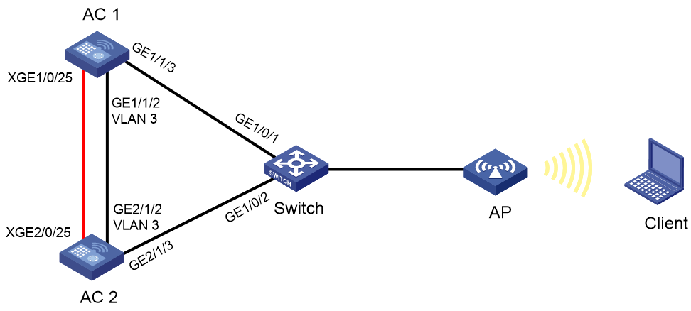
As shown in Figure 1, deploy two ACs (AC 1 and AC 2) for node redundancy and connect the ACs to a third-party switch on the network.
· Directly connect AC 1 and AC 2 to build an IRF fabric.
· To quickly detect a multi-active collision caused by IRF split, configure a minimum of one multi-active detection (MAD) mechanism. Because the switch does not support LACP MAD, this example uses ARP MAD instead.
· Configure the IRF fabric to establish a dynamic aggregate link with the switch to forward IRF service packets.
· Create VLAN 3 on the IRF fabric for ARP MAD.
Restrictions and guidelines
To ensure successful setup and maintenance of the IRF fabric, read the following information carefully.
IRF setup requirements
IRF fabric size
At the time of this writing, an IRF fabric can contain a maximum of two ACs.
Software version requirements
Make sure all IRF member devices run the same software image version.
To add a device of a different software version to the IRF fabric, make sure the software auto-update feature is enabled on the device for software synchronization. To verify the enabling status of the feature, execute the display irf command and then examine the Auto upgrade field. If the feature is disabled, use the irf auto-update enable command to enable it.
IRF connection requirements
To build a two-member IRF fabric, you can connect two devices directly or indirectly through a switch.
To build an IRF fabric that has more than two member devices, you must connect them through a switch.
IRF physical interface restrictions
When you use 100Base-FX/1000Base-X SFP ports or 10GBase-R SFP+ ports to establish IRF links, follow these guidelines:
· Do not use 100Base-FX/1000Base-X SFP ports with 100M transceiver modules.
· Do not use 10GBase-R SFP+ ports with 1G transceiver modules.
IRF port binding requirements
You can create only one IRF port on an AC. The IRF port is named irf-port n, where n is the IRF member ID of the AC.
When you bind physical interfaces to an IRF port, follow these restrictions and guidelines:
· The physical interfaces bound to an IRF port must be the same in speed.
· An IRF port can contain hybrid (control & data) channels, separate control and data channels, but not both. If you have bound a physical interface to the IRF port as a hybrid channel, you cannot bind additional physical interfaces to the IRF port as separate control or data channels. Conversely, if you have bound a physical interface to the IRF port as a separate data or control channel, you cannot bound additional physical interfaces as hybrid channels to the IRF port.
After you bind physical interfaces to the IRF port on an AC, you must save the configuration, and then restart the AC or activate the IRF port settings for the bindings to take effect.
Other configuration requirements
Make sure the following requirements are met:
|
Item |
Requirements |
|
Spanning tree feature |
· On the IRF members—To avoid loops, enable the spanning tree feature on the physical ports used for ARP MAD. Disable the spanning tree feature on the other physical ports. · On the switch—To avoid service interruption, disable the spanning tree feature on the physical ports used for IRF services. |
|
IRF member ID |
Assign a unique member ID to each member device. The member ID assigned to a device takes effect after the device restarts. |
|
Topo-domain ID |
Assign the same topo-domain ID and MAD domain ID to all member devices. |
Configure Layer 2 dynamic aggregate interfaces to transmit service packets after you have established the IRF fabric.
IRF merge guidelines
If the IRF fabrics to be merged use the same bridge MAC address, you must change the bridge MAC address of one fabric.
To merge split IRF fabrics, make sure the IRF configuration on their member devices has not changed after the split.
Feature configuration and compatibility on an IRF fabric
To avoid service interference, isolate service packets from IRF packets at Layer 2.
If a multicard link aggregation is established between the IRF fabric and a switch, do not configure per-packet load sharing on the link aggregation at the switch end.
NAT is not supported on an IRF fabric.
IRF fabric tuning and maintenance
You cannot bring down an IRF link by shutting down the network interface on the IRF standby device side if that link is the only control channel in up state on the device. To bring down the IRF link, execute the shutdown command to shut down the network interface on the master device side for the link.
Before you can remove a network interface from an IRF port while multiple correctly operating IRF links are present, you must execute the shutdown command to shut that network interface down.
To change the IRF member ID of a device, execute the irf member renumber command on the device, and then restart the device for the change to take effect. To avoid MAD failures or service interruption, make sure the new member ID is unique among all IRF members.
All members in an IRF fabric use the same MAD domain ID. To change the MAD domain ID, execute the irf domain command on the master device. Make sure the new MAD domain ID is unique among all IRF fabrics present on the network for correct IRF split detection.
Procedures
Configuring the switch
# Create Bridge-Aggregation 1 and configure Layer 2 aggregation group 1 to operate in dynamic aggregation mode.
<Switch> system-view
[Switch] interface bridge-aggregation 1
[Switch-Bridge-Aggregation1] link-aggregation mode dynamic
[Switch-Bridge-Aggregation1] quit
# Add GigabitEthernet 1/0/1 to aggregation group 1.
[Switch] interface gigabitethernet 1/0/1
[Switch-GigabitEthernet1/0/1] port link-aggregation group 1
[Switch-GigabitEthernet1/0/1] quit
# Add GigabitEthernet 1/0/2 to aggregation group 1.
[Switch] interface gigabitethernet 1/0/2
[Switch-GigabitEthernet1/0/2] port link-aggregation group 1
[Switch-GigabitEthernet1/0/2] quit
# Enable link-aggregation traffic redirection to ensure traffic continuity when a Selected port goes down.
[Switch] link-aggregation lacp traffic-redirect-notification enable
Configuring AC 1
1. Configure the IRF port:
# Shut down the interfaces to be bound to the IRF port. In this example, shut down Ten-GigabitEthernet 1/0/25.
<AC1> system-view
[AC1] interface ten-gigabitethernet 1/0/25
[AC1-Ten-GigabitEthernet1/0/25] shutdown
[AC1-Ten-GigabitEthernet1/0/25] quit
# Create IRF port 1 and add Ten-GigabitEthernet 1/0/25 to the IRF port.
[AC1] irf-port 1
[AC1-irf-port1] port group interface ten-gigabitethernet 1/0/25
[AC1-irf-port1] quit
# Bring up Ten-GigabitEthernet 1/0/25.
[AC1] interface ten-gigabitethernet 1/0/25
[AC1-Ten-GigabitEthernet1/0/25] undo shutdown
[AC1-Ten-GigabitEthernet1/0/25] quit
2. Set the IRF member priority.
In this example, set the IRF member priority of AC 1 to 2 for AC 1 to win the master election.
[AC1] irf member 1 priority 2
3. Save the running configuration.
[AC1] save
The current configuration will be written to the device. Are you sure? [Y/N]:y
Please input the file name(*.cfg)[cfa0:/startup.cfg]
(To leave the existing filename unchanged, press the enter key):
Validating file. Please wait...
Saved the current configuration to mainboard device successfully.
4. Activate the IRF port settings.
[AC1] irf-port-configuration active
Configuring AC 2
1. Set the IRF member ID:
# Set the member ID of AC 2 to 2.
<AC2> system-view
[AC2] irf member 1 renumber 2
Renumbering the member ID may result in configuration change or loss. Continue?[
Y/N]:y
[AC2] quit
# Restart AC 2 for the member ID to take effect.
<AC2> reboot
Start to check configuration with next startup configuration file, please wait..
.......DONE!
Current configuration may be lost after the reboot, save current configuration?
[Y/N]:y
Please input the file name(*.cfg)[cfa0:/startup.cfg]
(To leave the existing filename unchanged, press the enter key):
cfa0:/startup.cfg exists, overwrite? [Y/N]:y
Validating file. Please wait...
Saved the current configuration to mainboard device successfully.
This command will reboot the device. Continue? [Y/N]:y
Now rebooting, please wait...
2. Configure the IRF port:
# Shut down the interfaces to be bound to the IRF port. In this example, shut down Ten-GigabitEthernet 2/0/25.
<AC2> system-view
[AC2] interface ten-gigabitethernet 2/0/25
[AC2-Ten-GigabitEthernet2/0/25] shutdown
[AC2-Ten-GigabitEthernet2/0/25] quit
# Create IRF port 2 and bind Ten-GigabitEthernet 2/0/25 to the IRF port.
[AC2] irf-port 2
[AC2-irf-port2] port group interface ten-gigabitethernet 2/0/25
[AC2-irf-port2] quit
[AC2] interface ten-gigabitethernet 2/0/25
# Bring up Ten-GigabitEthernet 2/0/25.
[AC2-Ten-GigabitEthernet2/0/25] undo shutdown
[AC2-irf-port2] quit
3. Save the running configuration.
[AC2] save
The current configuration will be written to the device. Are you sure? [Y/N]:y
Please input the file name(*.cfg)[cfa0:/startup.cfg]
(To leave the existing filename unchanged, press the enter key):
Validating file. Please wait...
Saved the current configuration to mainboard device successfully.
4. Activate the IRF port settings.
[AC2] irf-port-configuration active
System is starting...
AC 1 and AC 2 perform master election. AC 2 fails the master election and restarts to form an IRF fabric with AC 1.
Configuring the IRF fabric
|
|
IMPORTANT: If the IRF fabric splits, the two ACs might operate with the same IP address on the network. To avoid IP conflict and other network issues, configure MAD. |
1. Change the system name to IRF.
<AC1> system-view
[AC1] system-name IRF
2. Specify member descriptions.
# Configure the description as AC 1 for IRF member 1 and AC 2 for IRF member 2.
[IRF] irf member 1 description AC 1
[IRF] irf member 2 description AC 2
3. Configure the IRF service VLAN:
# Create VLAN 101, assign an IP address to VLAN-interface 101, and enable periodic sending of gratuitous ARP packets.
[IRF] vlan 101
[IRF-vlan101] quit
[IRF] interface vlan-interface 101
[IRF-Vlan-interface101] ip address 10.128.52.250 255.255.255.0
[IRF-Vlan-interface101] arp send-gratuitous-arp interval 1000
4. Configure link aggregation:
# Create Bridge-Aggregation 1 and configure Layer 2 aggregation group 1 to operate in dynamic aggregation mode.
[IRF] interface bridge-aggregation 1
[IRF-Bridge-Aggregation1] link-aggregation mode dynamic
[IRF-Bridge-Aggregation1] port link-type trunk
[IRF-Bridge-Aggregation1] undo port trunk permit vlan 1
[IRF-Bridge-Aggregation1] port trunk permit vlan 101
# Add GigabitEthernet 1/1/3 to aggregation group 1.
[IRF] interface gigabitethernet 1/1/3
[IRF-GigabitEthernet1/1/3] port link-type trunk
[IRF-GigabitEthernet1/1/3] port trunk permit vlan 101
[IRF-GigabitEthernet1/1/3] undo port trunk permit vlan 1
[IRF-GigabitEthernet1/1/3] port link-aggregation group 1
[IRF-GigabitEthernet1/1/3] quit
# Add GigabitEthernet 2/1/3 to aggregation group 1.
[IRF] interface gigabitethernet 2/1/3
[IRF-GigabitEthernet2/1/3] port link-type trunk
[IRF-GigabitEthernet2/1/3] port trunk permit vlan 101
[IRF-GigabitEthernet2/1/3] undo port trunk permit vlan 1
[IRF-GigabitEthernet2/1/3] port link-aggregation group 1
[IRF-GigabitEthernet2/1/3] quit
5. Configure ARP MAD:
|
|
IMPORTANT: If VLAN 1 is not used for services, enable the spanning tree feature also on VLAN 1 to prevent miscabling of idle physical ports in VLAN 1 from causing loops. |
# Enable the spanning tree feature globally, set its operating mode to PVST, and disable the feature on the all VLANs except for VLAN 3 (the VLAN for ARP MAD).
[IRF] stp global enable
[IRF] stp mode pvst
[IRF] undo stp vlan 2 4 to 4094 enable
# Configure the IRF bridge MAC address to change as soon as the address owner leaves.
[IRF] undo irf mac-address persistent
# Set the IRF domain ID to 1.
[IRF] irf domain 1
# Create VLAN 3, and assign Gigabitethernet 1/1/2 on AC 1 and Gigabitethernet 2/1/2 on AC 2 to VLAN 3.
[IRF] vlan 3
[IRF-vlan3] quit
[IRF] interface Gigabitethernet1/1/2
[IRF-Gigabitethernet1/1/2] port access vlan 3
[IRF-Gigabitethernet1/1/2] quit
[IRF] interface Gigabitethernet2/1/2
[IRF-Gigabitethernet2/1/2] port access vlan 3
[IRF-Gigabitethernet2/1/2] quit
# Create VLAN-interface 3, assign an IP address to the interface, and enable ARP MAD.
[IRF] interface vlan-interface 3
[IRF-Vlan-interface3] ip address 192.168.2.1 24
[IRF-Vlan-interface3] mad arp enable
You need to assign a domain ID (range: 0-4294967295)
[Current domain is: 0]: 1
The assigned domain ID is: 1
6. Configure gratuitous ARP packet retransmission.
# Set the maximum number of gratuitous ARP packet transmissions and the transmission interval for a device MAC address change.
[IRF] gratuitous-arp mac-change retransmit 3 interval 2
Verifying the configuration
1. Verify that AC 1 is the master device, with a higher priority than AC 2.
[IRF] display irf
Member ID Role Priority CPU MAC Description
*1 Master 2 50da-0051-2608 AC 1
+2 Standby 1 50da-0051-2670 AC 2
--------------------------------------------------
The asterisk (*) indicates the master.
The plus sign (+) indicates the device through which you are logged in.
The right angle bracket (>) indicates the device's stack capability is disabled.
Bridge MAC of the IRF: 50da-0051-2608
Auto upgrade : Enabled
MAC persistence : Disabled
Topo-domain ID : 0
Auto merge : Enabled
2. Verify that both IRF ports are in Up state.
[IRF] display irf link
Member ID Member Interfaces Status
1 XGE1/0/25(ctrl&data) Up
2 XGE2/0/25(ctrl&data) Up
3. Verify that ARP MAD is configured correctly.
[IRF] display mad verbose
Multi-active recovery state: No
Excluded ports (user-configured):
Excluded ports (system-configured):
Ten-GigabitEthernet1/0/25
Ten-GigabitEthernet2/0/25
MAD ARP enabled interface:
Vlan-interface3
MAD ND disabled.
MAD LACP disabled.
MAD BFD disabled.
Configuration files
· IRF
#
sysname IRF
#
undo irf mac-address persistent
irf auto-update enable
irf auto-merge enable
irf member 1 priority 2
irf member 2 priority 1
irf member 1 description AC 1
irf member 2 description AC 2
#
link-aggregation lacp traffic-redirect-notification enable
#
irf-port 1
port group interface Ten-GigabitEthernet1/0/25
#
irf-port 2
port group interface Ten-GigabitEthernet2/0/25
#
vlan 3
#
interface Bridge-Aggregation1
port link-type trunk
undo port trunk permit vlan 1
port trunk permit vlan 101
link-aggregation mode dynamic
#
vlan 101
#
interface Vlan-interface3
ip address 192.168.10.10 255.255.255.0
mad arp enable
#
interface Vlan-interface101
ip address 10.128.52.250 255.255.255.0
arp send-gratuitous-arp interval 1000
#
interface GigabitEthernet1/1/2
port access vlan 3
#
interface GigabitEthernet1/1/3
port link-type trunk
undo port trunk permit vlan 1
port trunk permit vlan 101
port link-aggregation group 1
#
interface GigabitEthernet2/1/2
port access vlan 3
#
interface GigabitEthernet2/1/3
port link-type trunk
undo port trunk permit vlan 1
port trunk permit vlan 101
port link-aggregation group 1
#
undo stp vlan 2 4 to 4094 enable
stp mode pvst
stp global enable
#
gratuitous-arp mac-change retransmit 3 interval 2
#
· Switch
#
link-aggregation lacp traffic-redirect-notification enable
#
interface Bridge-Aggregation1
link-aggregation mode dynamic
#
interface GigabitEthernet1/0/1
port link-aggregation group 1
#
interface GigabitEthernet1/0/2
port link-aggregation group 1
#
Related documentation
· High Availability Command Reference in H3C Access Controllers Command References
· High Availability Configuration Guide in H3C Access Controllers Configuration Guides
· Network Connectivity Command Reference in H3C Access Controllers Command References
· Network Connectivity Configuration Guide in H3C Access Controllers Configuration Guides
