- Table of Contents
-
- H3C CR16000-M Routers Installation Guide-5W102
- 00-Preface
- 01-Safety precautions
- 02-Preparing for installation
- 03-Installing the router
- 04-Installing removable components
- 05-Connecting cables
- 06-Verifying the installation
- 07-Starting and configuring the router
- 08-Replacement procedures
- 09-Troubleshooting
- 10-Appendix A Engineering labels
- 11-Appendix B Cable assembling and management
- 12-Appendix C Repackaging the Router
- Related Documents
-
| Title | Size | Download |
|---|---|---|
| 11-Appendix B Cable assembling and management | 4.47 MB |
Contents
Appendix B Cable assembling and management
Connecting or disconnecting cable connectors
Connecting or disconnecting a ring terminal
Connecting or disconnecting an RJ-45 connector
Connecting or disconnecting a fiber connector
Appendix B Cable assembling and management
This section describes attaching cable connectors (ring terminal or RJ connector) to cables.
Connectors, cables, and tools to use might vary by vendor. Figures in this section are for illustration only.
Assembling a cable
Use professional tools and devices and follow the correct steps when you attach a cable connector to a cable.
Prerequisites
Examining the cable
If there is visible dirt on the cable surface, clean it before assembly.
Examine the appearance of the cable. If any of the following conditions exists, do not use the section of the cable:
· The surface of the cable has an obvious bulge, dent, defect, or scratch.
· The wired shield is incomplete or fractured.
· Brittle cracks appear after you lightly shake or rub the cable.
Examining the connector
Examine the connector. If any of the following conditions exists, do not use the connector:
· The connector has obvious damage, cracks, rust, or rust spots.
· The plating layer of the pins on the RJ-45 connector is off or obviously unevenly plated.
· The pins on the RJ-45 connector are damaged, missing, broken, or bent.
· Foreign objects or conductive substances, such as metal chips, exist in the space where the pins of the RJ-45 connector are located.
Restrictions and guidelines
When you assemble a cable, pinch the connector instead of pulling or stretching the cable.
When you cut a cable or strip the insulation sleeve, follow these restrictions and guidelines:
· The length of the cable should allow for the loss of length during processing.
· Wound a long cable into a coil, and tie the coil with a rope or wrapping film. The inner diameter of the bobbin must be greater than 20 times the outer diameter of the cable.
· After cutting the wire, make sure the visible sheath section is neat.
· When stripping the insulation sleeve, do not damage the shielding layer, cable conductor, or cable sleeves that do not require treatment.
· It is strictly forbidden to touch the stripped cable conductors directly with bare hands.
· The stripped cable conductor must be processed in time to prevent oxidation of the conductor surface.
When you attach a connector to a cable, follow these restrictions and guidelines:
· After crimping, make sure the connector and cable are tightly bonded.
· Make sure the cable conductor is not exposed, and cut off the exposed conductor in time.
· The crimping should be completed once, and avoid secondary crimping.
Attaching a ring terminal
Ring terminal and cable components
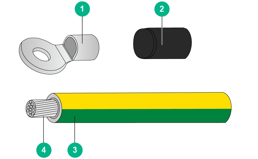
FigureB-1 Ring terminal and cable components
|
(1) Ring terminal |
(2) Heat-shrink tubing |
|
(3) Insulation sleeve |
(4) Cable connector |
Procedure
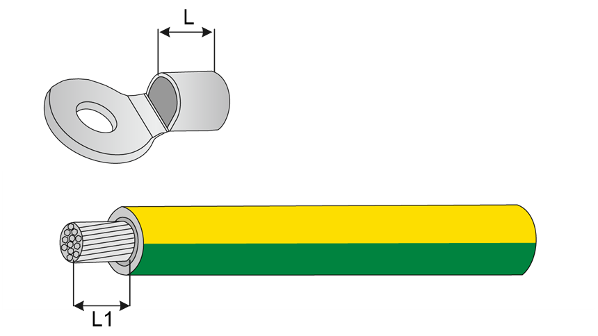
1. Strip off an appropriate length (length L1 as shown in the figure) of the cable insulation sleeve.
FigureB-2 Cable conductor length
|
|
NOTE: You can adjust the length of L1 as needed. Typically, L1 is the L plus 1 to 2 mm. |
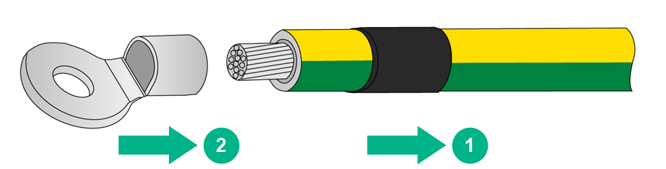
2. Route the cable through a heat-shrink tubing.
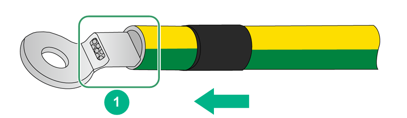
3. Attach the ring terminal to the cable conductor, and press the ring terminal against the cable sheath.
FigureB-3 Attaching the ring terminal
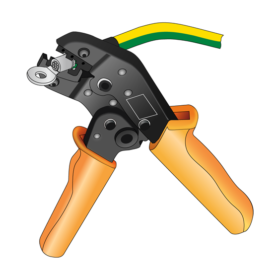
4. Use a crimping tool to crimp the tail of the ring terminal.
The shape of the end face after crimping varies by crimping tool.
FigureB-4 Crimping the ring terminal
5. Cover the joint with the heat-shrink tubing.
FigureB-5 Covering the joint with the heat-shrink tubing
|
(1) Crimping section |
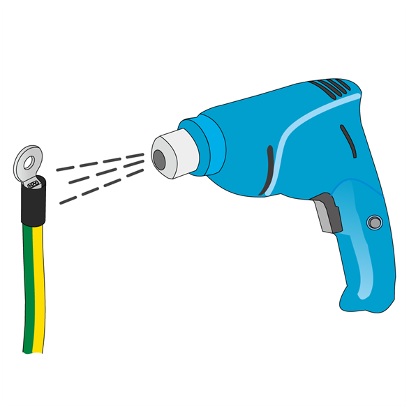
6. Use a blow dryer to heat the tubing until the tubing closely covers the cable.
FigureB-6 Shrinking the tubing
|
|
IMPORTANT: Do not heat the tube for a long time in case burning the insulation sleeve. |
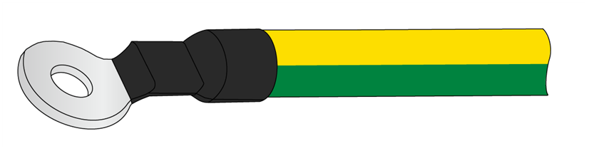
FigureB-7 Cable attached with a ring terminal
Attaching an RJ-45 connector
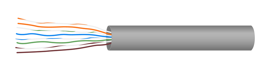
RJ-45 connector and twisted pair cable
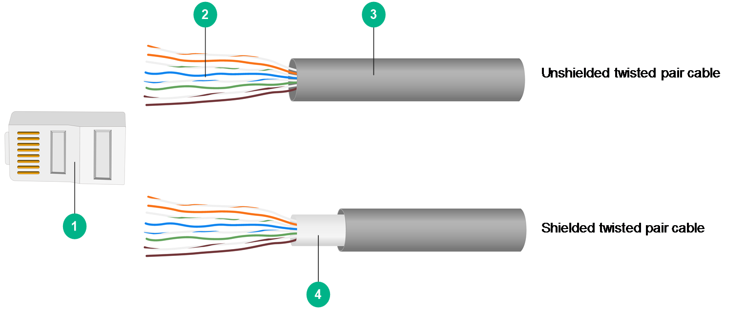
FigureB-8 Ring terminal and cable components
|
(1) RJ-45 connector |
(2) Twisted pair cable |
|
(3) Insulation sleeve |
(4) Shielding layer |
|
|
NOTE: · The difference between shielded twisted pair and unshielded twisted pair cables is that a shielded twisted pair cable as a shielding layer made of aluminum foil. · The difference between shielded RJ-45 and unshielded RJ-45 connectors is that a shielded RJ-45 connector has a metal housing. |
Procedure
The procedure is similar for shielded twisted pair and unshielded twisted pair cables. This section uses an unshielded twisted pair cable as an example.
To attach an RJ-45 connector:
1. Use the crimping pliers to trim one end of the cable, put the cable end into the knife edge for wire stripping, hold the wire-crimping pliers slightly and rotate slowly. Let the knife edge peel off the insulation sleeve to expose the twisted pair.
FigureB-9 Peeling off the insulation sleeve
|
|
NOTE: · When stripping the shield, do not scratch the insulation layer of the core wires. · The length of the crimper stop from the stripping blade is usually exactly the length of an RJ-45 connector, which can effectively avoid stripping the wire too long or too short. |
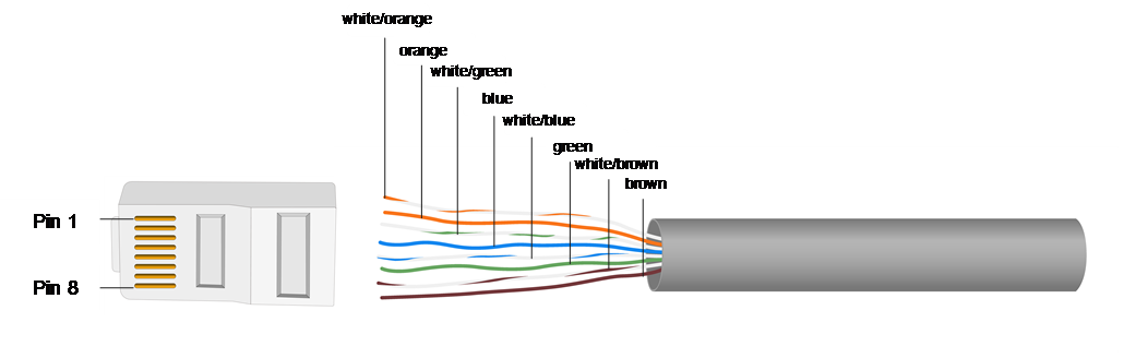
2. Align the wires as required.
FigureB-10 Aligning the wires (straight-through network cable)
|
|
NOTE: According to the different wiring relationship, the network cable is divided into straight-through network cable and crossover network cable. This section uses a straight-through cable as an example. For more information, see H3C CR16000-M Router Hardware Options. |
3. Use the cutting edge of the wire-crimping pliers to trim the top of the twisted pair cable neatly. Slowly and forcefully insert the 8 wired into the wire grooves in the RJ-45 connector at the same time, and insert them all the way to the top of the grooves.
Make sure the wires extend to the front of the RJ-45 end and make good contact with the metal contacts in the RJ-45 end.
4. Crimp the RJ-45 connector with the crimping pliers until you hear a click.
5. Repeat steps 2 to 5 to attach a connector to the other end of the cable.
Verifying the cable
Examine the assembled twisted pair connectors. If the cable cannot meet the following requirements, reassemble the cable:
· The connector surface must not contain obvious foreign objects, dirt or rust.
· The wires must be extended to the front of the RJ-45 end as close as possible.
· The end and front faces of the metal plating and the plastic spacer are not skewed or defective.
· The wires are arranged in the correct sequence.
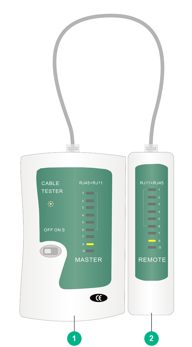
Use a cable tester to verify the connectivity of the cable:
1. Insert the cable connectors into the RJ-45 female ports on the tester in turn.
2. Gently shake the connectors of the twisted pair cable to confirm that the connectors are in reliable contact with the RJ-45 female ports.
3. Switch on the tester, and view the LEDs on the master and remote terminals.
¡ For a straight-through cable, when master LEDs 1 through 8 and G are lighted in sequence, the same-numbered LEDs on the remote terminal should be lighted.
¡ For a crossover cable, when master LEDs 1 through 8 and G are lighted in sequence, the LED lighting sequence on the remote terminal should be 3-6-1-4-5-2-7-8-G.
FigureB-11 Cable tester (straight-through network cable)
|
(1) Master terminal |
(2) Remote terminal |
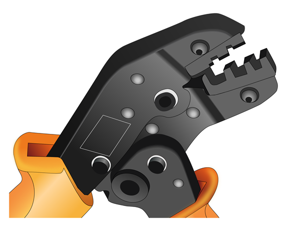
Replacing the mould
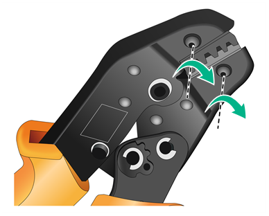
1. Loosen the two screws of the mould counterclockwise.
FigureB-12 Loosening the screws

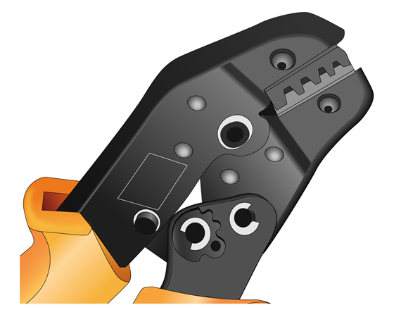
2. Squeeze the handle of the crimping pliers for the self-locking lock to pop open. The jaws of the crimping pliers will automatically open.
FigureB-13 Opening the crimping pliers jaws
3. Remove the mould.
FigureB-14 Removing the mould
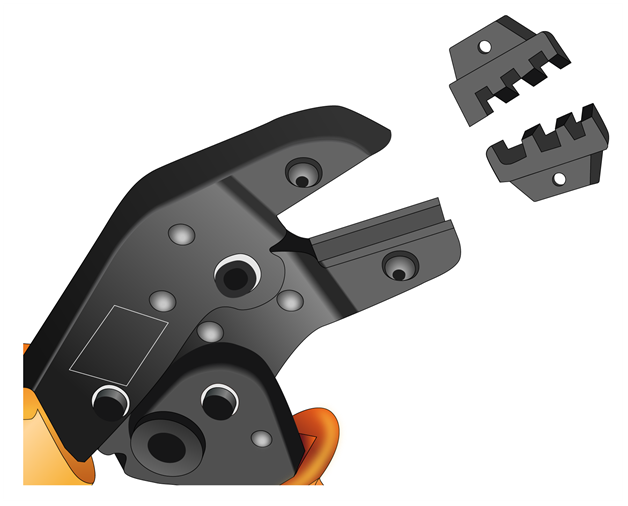
4. Install the new mould as shown in FigureB-15.
FigureB-15 Installing a mould
|
|
NOTE: Keep the short side of the mould inwards and the long side outwards. The teeth of the mould now go from largest toward the inside to smallest toward the outside. |
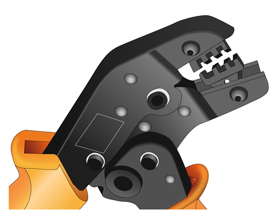
5. Hold the handles of the crimping pliers tightly to match the mould and the jaw completely. Align the screw holes.
FigureB-16 Aligning the screw holes
6. Hold the handles of the crimping pliers with one hand, and tighten the two fastening screws.
FigureB-17 Tightening the fastening screws
Connecting or disconnecting cable connectors
Restrictions and guidelines
· During operation, use special tools and equipment, and follow the correct steps.
· When connecting cable connectors, do not use any excessive force or pull the cable.
· If you cannot insert a connector into a port completely, do not use excessive force. Pull out the connector, verify that the connector matches the port and the connector is oriented correctly, and then try again.
· When you tightening a terminal screw, make sure that the connector and its mating end fit well. As a best practice, use a flat-head or Phillips screwdriver instead of a bare hand, and use moderate force. Do not fasten the screw too tight. If you encounter any resistance, do not force screwing. Identify the reason so as not to damage the screw or the terminal stud.
· When cable connectors or optical fiber connectors are deployed with a high density, use special pliers (such as wire pliers and fiber pliers) to remove a connector.
· Do not twist, bend, stretch, or squeeze fibers during installation.
· Cover unused fiber connectors with dust-proof caps. Remove the dust-proof caps only when you are about to use the fiber connectors.
Connecting or disconnecting a ring terminal
|
|
CAUTION: · Ring terminals might rotate. Make sure a ring terminal cannot contact any adjacent metal structural parts or studs. · As a best practice, do not connect two ring terminals to one stud. |
Connecting a ring terminal
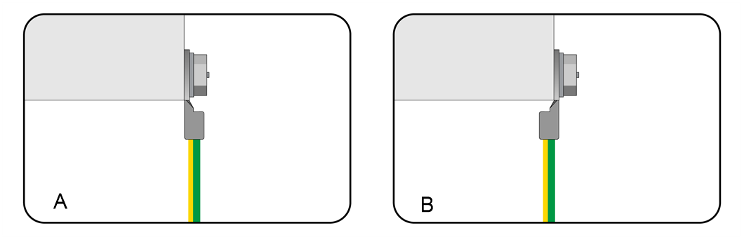
1. Align the ring terminal with the stud, and fasten the hexagonal nut clockwise.
FigureB-18 Connecting a ring terminal

|
|
NOTE: You can attach a ring terminal with in direction A or B as shown in FigureB-19. As a best practice, use direction A. |
FigureB-19 Ring terminal installation directions
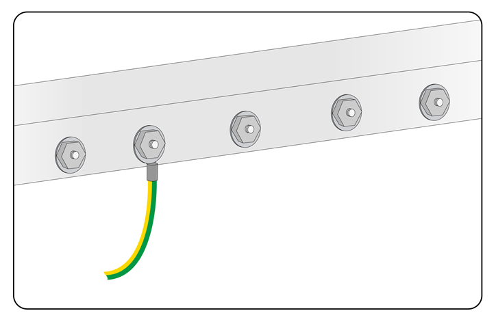
2. Slightly pull the cable and make sure the cable is securely connected.
FigureB-20 Ring terminal connected
Disconnecting a ring terminal
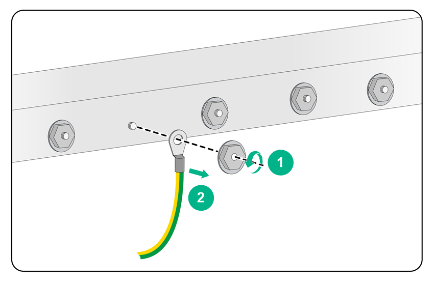
Loosen the hexagonal nut anticlockwise to remove it, and then disconnect the ring terminal.
FigureB-21 Disconnecting a ring terminal
Connecting or disconnecting an RJ-45 connector
Connecting an RJ-45 connector
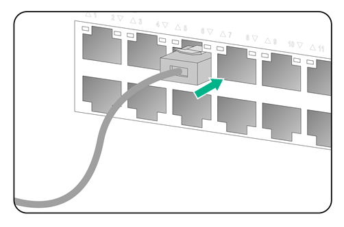
Align the connector with the network port, pinch the end of the connector and insert it into the port. Press the connector until you hear a click. Slightly pull the cable and make sure the cable is connected securely.
FigureB-22 Connecting an RJ-45 connector
Disconnecting an RJ-45 connector
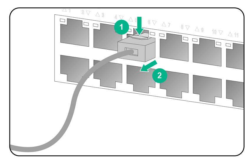
Press the locking clip to disengage the connector from the port, and pull out the connector.
FigureB-23 Disconnecting an RJ-45 connector
Connecting or disconnecting a fiber connector
Connecting or disconnecting an LC-type fiber connector
Connecting an LC-type connector
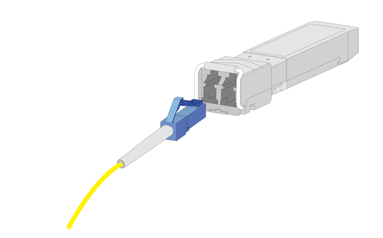
1. Remove the dust-proof cap and keep the cap for future use.
2. Align the connector with the fiber port.
FigureB-24 Aligning the connector with the fiber port
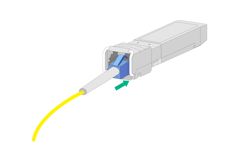
3. Insert the connector into the port until you hear a click.
Slightly pull the fiber and make sure the fiber is connected securely.
FigureB-25 Inserting the connector
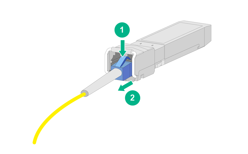
Disconnecting an LC-type connector
Press the locking tab to disengage the connector from the port, and then slightly pull the connector out.
FigureB-26 Disconnecting the connector
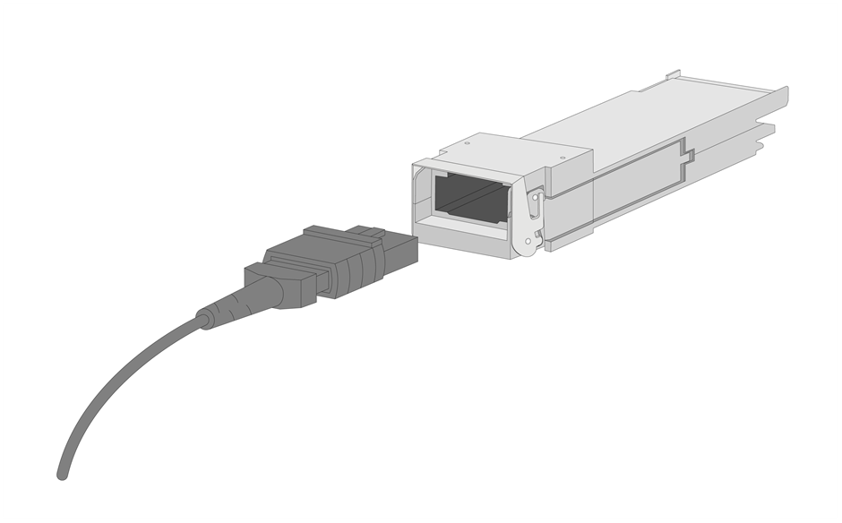
Connecting or disconnecting an MPO-type fiber connector
Connecting an MPO-type connector
1. Remove the dust-proof cap and keep the cap for future use.
2. Align the connector with the fiber port.
FigureB-27 Aligning the connector with the fiber port
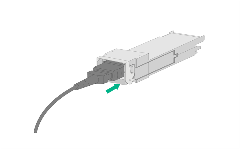
3. Pinch the part of the connector marked with PUSH, and insert the connector into the port until you hear a click.
Slightly pull the fiber and make sure the fiber is connected securely.
FigureB-28 Inserting the connector
Disconnecting an MPO-type connector
Pinch the part of the connector marked with PULL to disengage the connector from the port, and then slightly pull the connector out.
FigureB-29 Disconnecting the connector

Cleaning a fiber connector
To clean a fiber connector without guide pins:
1. Dip a lint-free cotton cloth in alcohol, spin the cloth dry, and clean the end surface and cylindrical surface of the connector ceramic pins.
2. Clean the pins again by using lint-free cotton. If necessary, clean the pins by using an air gun. Ensure that the pins are free from any fiber or debris.
To clean a fiber connector with guide pins:
1. Fold a piece of lint-free cotton and dip it in alcohol. Then, use the cotton to clean the pins.
2. Clean the pins again by using a new piece of lint-free cotton without alcohol.
3. Use an air gun to remove any residual objects on the pins.
Managing cables
Figures in this section are for illustration only.
Label cables before you route or bundle them. For more information about labeling cables, see "Appendix A Engineering labels."
General cabling requirements
Minimum curvature radius of cables
· The curvature radius of an attached power cord, communication cable, or ribbon cable should be a minimum of five times of the cable’s outer diameter. If the cable is frequently bent, connected and removed, the curvature radius should be a minimum of seven times the cable's outer diameter.
· The curvature radius of an ordinary attached coaxial cable should be a minimum of seven times of the cable's outer diameter. If the coaxial cable is frequently bent, connected and removed, the curvature radius should be a minimum of 10 times of the cable's outer diameter.
· The curvature radius of a high-speed cable should be a minimum of five times of the cable's outer diameter. If the coaxial cable is frequently bent, connected and removed, the curvature radius should be a minimum of 10 times of the cable's outer diameter.
Minimum curvature radius of fibers
· When the fiber is wrapped up around the cabling plate, the diameter of the cabling plate should be a minimum of 25 times of the fiber's diameter.
· When the fiber is being moved, the curvature radius of the fiber should be a minimum of 20 times of the fiber's diameter.
· When the fiber is attached, the curvature radius of the fiber should be a minimum of 10 times of the fiber's diameter.
|
|
NOTE: The fiber's diameter refers to the outer diameter of the fiber jacket. Typically, the diameter of a single-core fiber is 0.9 mm (0.04 in), 2.0 mm (0.08 in), or 3.0 mm (0.12 in). |
Cable management guidelines
When you route and bundle up cables, follow these guidelines:
· Bind cables neatly for easy maintenance and expansion.
· The cable management brackets and cable routing slots, inside or outside the rack, are smooth and have no sharp edges or tips.
· Route different types of cables (for example, power cords and signal cables) separately. If they are close to one another, cross them over one another. If you route them in parallel, make sure the space between a power cord bundle and a signal cable bundle is equal to or greater than 30 mm (1.18 in).
· Use the correct ties to bind the cables. Do not bind cables with joined ties.
· The distances between cable ties must be three to four times of the cable diameter.
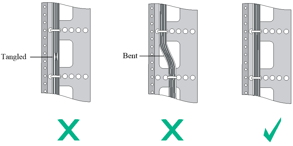
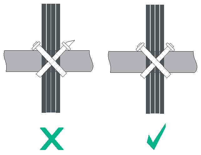
· Bind and route the cables neatly inside the rack, and make sure the cables are not kinked or bent. Do not tie cables or bundles in a knot.
FigureB-30 Correct and incorrect cable binding
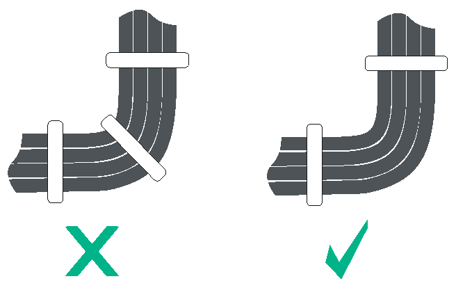
· When you bend cables, bind cables as shown in FigureB-31. To avoid cable core break due to excessive stress, do not tie up the cables in the bending area. The cable bend radius at connectors must be a minimum of 5 times the cable diameter, and must be a minimum of 5 times the cable diameter away from the connectors.
· When you route cables through sharp sheet metal penetration points or along sharp edges of mechanical parts, use bushings or take any other action to protect the cables from being cut or abraded. The sheet metal penetration points must be smooth and fully rounded.
· When optical fibers are inserted into a protective tube, wrap tapes around the edges of the protective tube to protect optical fibers from being cut.
· After binding the cables, cut the excess from the ties, leaving no sharp or angular tips. See FigureB-32.
FigureB-32 Cutting the cable ties
· Route, bind, and attach excess cables for easy, safe maintenance activities and proper operations.
· Do not tie the power cords to the slide rails.
· When you connect a cable to an articulated part, for example, when you connect a grounding cable to a rack door, leave enough slack in cables and make sure they are not stressed from any movement of the part.
· Cables must be protected at points where they might rub or come in contact with sharp edges or heated areas. Use high temperature cables near heat sources.
· Fasten heavy or rigid power cords at the connectors to relief stress.
Cable management
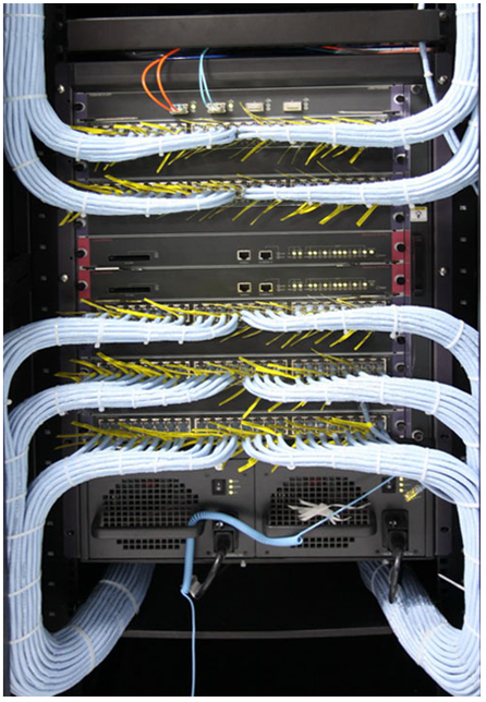
Network cable management
FigureB-33 Network cable management
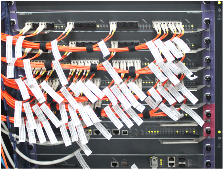
Optical fiber management
|
|
CAUTION: The core of optical fibers is thin and fragile. Do not use cable ties to bind the optical fibers. Use soft binding tapes to carefully bind optical fibers. Avoid excessive force. For more information, see the binding tape use instructions. |
FigureB-34 Optical fiber management
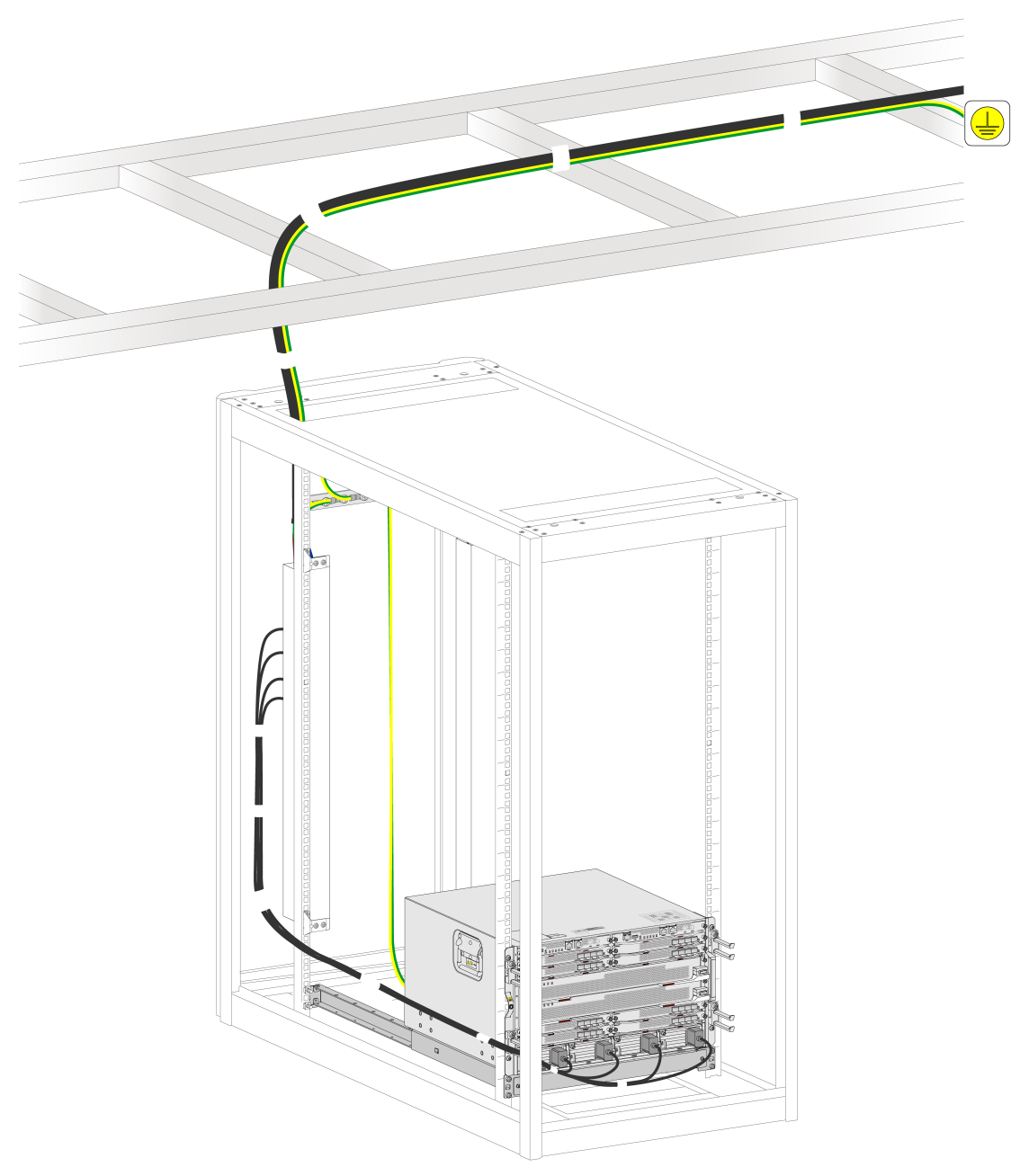
Power cord management
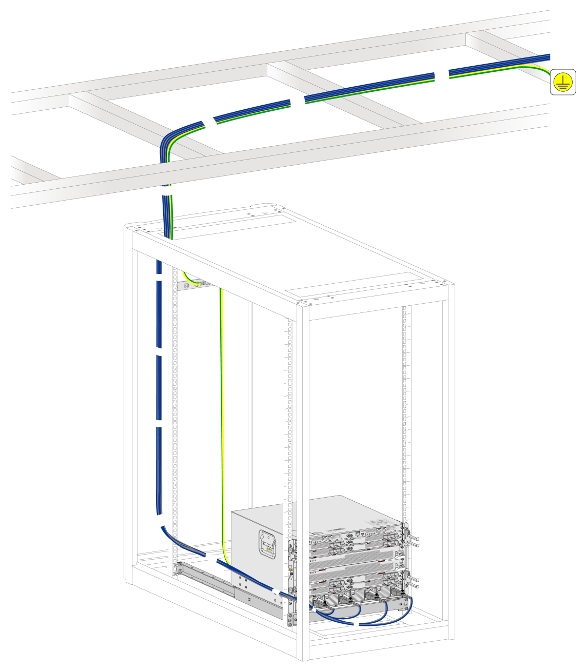
Route the power cords according to the actual conditions in the equipment room, such as the locations of power distribution cabinets, receptacles, and lightning protection boxes. When routing AC power cords, connect them to a power distribution cabinet in the equipment room through PDUs on the rack or through a grounding strip. When routing DC power cords, connect them directly to a power distribution cabinet in the equipment room.
For future device maintenance, avoid blocking the device modules, such as fan trays, when routing power cords.
FigureB-35 Routing AC power cords
FigureB-36 Routing DC power cords
|
|
NOTE: If the power cord cannot be threaded from the side due to insufficient space at the side of the cabinet, you can route the power cord through the bottom to the front. |
