- Table of Contents
-
- H3C CR16000-M Routers Installation Guide-5W102
- 00-Preface
- 01-Safety precautions
- 02-Preparing for installation
- 03-Installing the router
- 04-Installing removable components
- 05-Connecting cables
- 06-Verifying the installation
- 07-Starting and configuring the router
- 08-Replacement procedures
- 09-Troubleshooting
- 10-Appendix A Engineering labels
- 11-Appendix B Cable assembling and management
- 12-Appendix C Repackaging the Router
- Related Documents
-
| Title | Size | Download |
|---|---|---|
| 04-Installing removable components | 1.81 MB |
4 Installing removable components
Installing MPUs/interface modules
Installing switching fabric modules
Installing the cable management brackets
Connecting an AC or HVDC power cord for a PSR2500B-12AHD-F power supply
4 Installing removable components
There is no required order for installing removable components.
|
|
NOTE: Keep the packaging, including packaging cartons and bags of the chassis and components secure for future use. |
Attaching an ESD wrist strap
|
|
CAUTION: · Use a multimeter to measure the resistance of the ESD wrist strap. Be sure that the resistance reading between your body and the ground is 1 to 10 megohms. · To connect the ESD wrist strap to the ESD jack on the chassis, make sure the router is grounded reliably. For the grounding method for the router, see "Grounding the router." |
The router is shipped with an ESD wrist strap. To minimize ESD damage to electronic components, wear the ESD wrist strap when you install a removable component and make sure the strap is reliably grounded when installing cards.
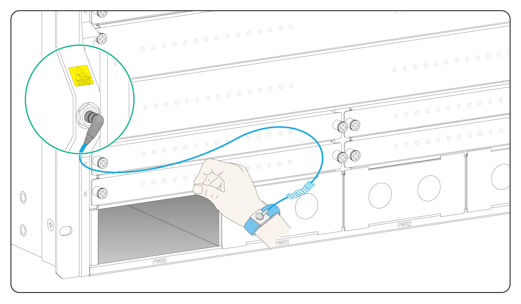
To use an ESD wrist strap:
1. Make sure the router is reliably grounded. For information about how to ground your router, see "Grounding the router."
2. Put on the wrist strap.
3. Tighten the wrist strap to keep good skin contact.
4. As shown in Figure4-1, insert the ESD wrist strap into the ESD jack on the router chassis, or attach it to the grounding post of the chassis with an alligator clip.
Figure4-1 Attaching an ESD wrist strap
Installing MPUs/interface modules
|
|
CAUTION: · To avoid damages to the backplane, make sure the card connector is not broken or blocked before inserting the card into the chassis. · When installing a card, make sure its PCB side faces upward. · For adequate cooling and ventilation, install a filler panel in each unused slots. MPUs and interface module slots can use the same type of filler panel. |
The installation procedure is the same for MPUs and interface modules. The following procedure uses an MPU as an example.
To install an MPU:
1. Wear an ESD wrist strap, and make sure it makes good skin contact and is reliably grounded. For more information, see "Attaching an ESD wrist strap."
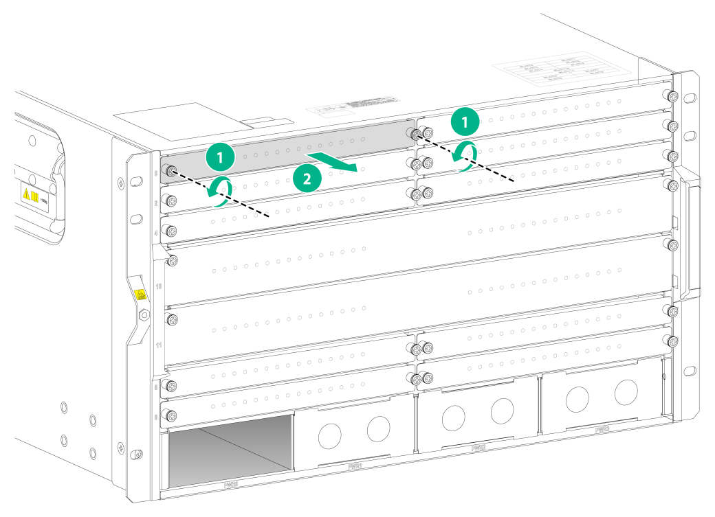
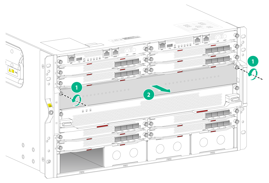
2. Remove the filler panel (if any) from the target slot.
Keep the filler panel secure for future use.
Figure4-2 Removing the filler panel from the target MPU slot
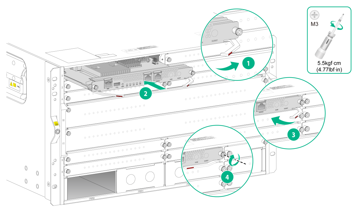
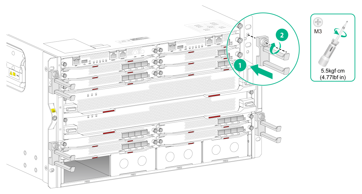
3. As shown by callout 1 in Figure4-3, open the ejector levers of the MPU.
4. As shown by callout 2 in Figure4-3, insert the MPU into the slot along the guide rails until the ejector levers engage the slot edges.
5. As shown by callout 3 in Figure4-3, close the ejector levers so that the MPU front panel is flush with the slot.
6. As shown by callout 4 in Figure4-3, fasten the captive screws on the MPU.
Figure4-3 Installing an MPU
Installing switching fabric modules
1. Wear an ESD wrist strap, and make sure it makes good skin contact and is reliably grounded. For more information, see "Attaching an ESD wrist strap."
2. Remove the filler panel (if any) from the target switching fabric module slot.
Keep the filler panel secure for future use.
Figure4-4 Remove the filler panel from the target switching fabric module slot
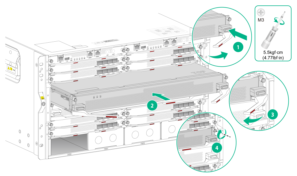
3. As shown by callout 1 in Figure4-5, press the ejector buttons of the two ejector levers simultaneously to release the ejector levels.
4. As shown by callout 2 in Figure4-5, orient the switching fabric module with the side that has the "TOP " sign facing upward, align the card with the target switching fabric module slot, and then insert it into the slot along the guide rails until the ejector levers engages the slot edges.
5. As shown by callout 3 in Figure4-5, close the ejector levers until the front panel of the switching fabric module is flush with the slot.
6. As shown by callout 4 in Figure4-5, use a Phillips screwdriver to fasten the captive screws on the switching fabric module.
Figure4-5 Installing a switching fabric module
Installing the cable management brackets
1. Unpack the cable management brackets from the accessory box.
2. Place a cable management bracket against the mounting bracket with the screw on the cable management bracket aligned with the screw hole in the mounting bracket.
3. Use a screwdriver to fasten the screw.
Figure4-6 Installing cable management brackets
Installing a power supply
|
|
CAUTION: Provide a circuit breaker for each power supply and make sure the circuit breaker is off before installing the power supply. |
The router supports N+1 or N+N power supply redundancy. You can select AC or DC power supplies for the router.
|
|
WARNING! To avoid device damage and bodily injury, strictly follow the procedure in Figure4-1 to install a power supply. |
Figure4-7 Power supply installation flowchart
![]()
Installing a power supply
|
|
WARNING! To avoid power supply damage or bodily injury, support the power supply bottom to move a power supply. Do not hold the power supply handle to move it. |
|
|
CAUTION: Do not install power supplies of different models on the same router. |
The installation procedure is the same for AC and DC power supplies. The following procedure installs an AC power supply.
The router is shipped without filler panels in some power supply slots. The figures in this section are for illustration only.
To install a power supply:
1. Wear an ESD wrist strap and make sure it makes good skin contact and is reliably grounded. For more information, see "Attaching an ESD wrist strap."
2. Remove the filler panel, if any, from the target power supply slot.
3. Unpack the power supply.
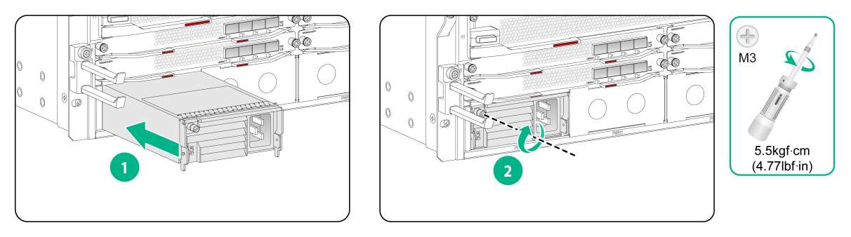
4. As shown by callout 1 in Figure4-8, grasping the handle of the power supply with one hand and supporting the power supply bottom with the other, push the power supply along the guide rails into the slot.
5. Press the handle into the slot after the power supply is seated fully in the slot.
6. Use a Phillips screwdriver to fasten the captive screw on the power supply to secure the power supply in the chassis.
Figure4-8 Installing a power supply
Connecting an AC power cord
|
|
CAUTION: · Before you connect an AC power cord, make sure the circuit breaker for the power cord is turned off. · Use an AC power cord with a straight connector for the router |
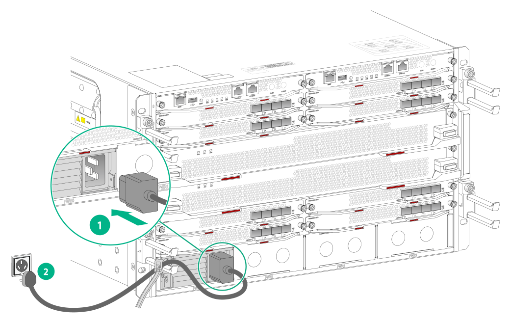
To connect an AC power cord:
1. Insert the connector of the power cord into the power receptacle on the power supply, and use a releasable cable tie to secure the power cord to the nearby cable management bracket.
2. Connect the other end of the power cord to a power outlet of the AC power source.
Figure4-9 Connecting an AC power cord
Connecting a DC power cord
|
|
WARNING! · Make sure each DC power cord has a separate circuit breaker. · When connecting a DC power cord to the power input terminal, make sure the circuit breaker for the input terminal has been turned off. |
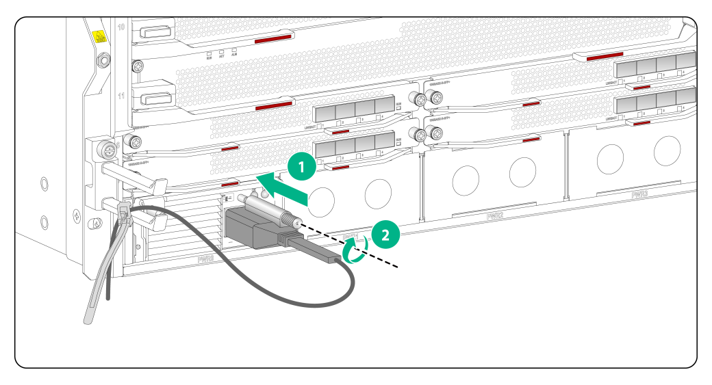
Connecting the DC power cord for a PSR2400-12D power supply
1. Insert the connector of the power cord into the power receptacle on the power supply.
2. Fasten the screw to secure the power cord, and use a cable tie to secure the power cord to the nearby cable management bracket.
3. Connect the other end of the DC power cord to a DC power source, with the wire marked with –48V connected to the negative terminal (–48V) and the wire marked with RTN connected to the RTN terminal (RTN).
Figure4-10 Connecting the DC power cord for a PSR2400-12D power supply
Connecting the DC power cord for a PSR2400-D power supply
|
|
IMPORTANT: To meet the current requirements and match the terminals on the PSR2400-D power supplies, use the power cords or lug terminals provided by H3C. |
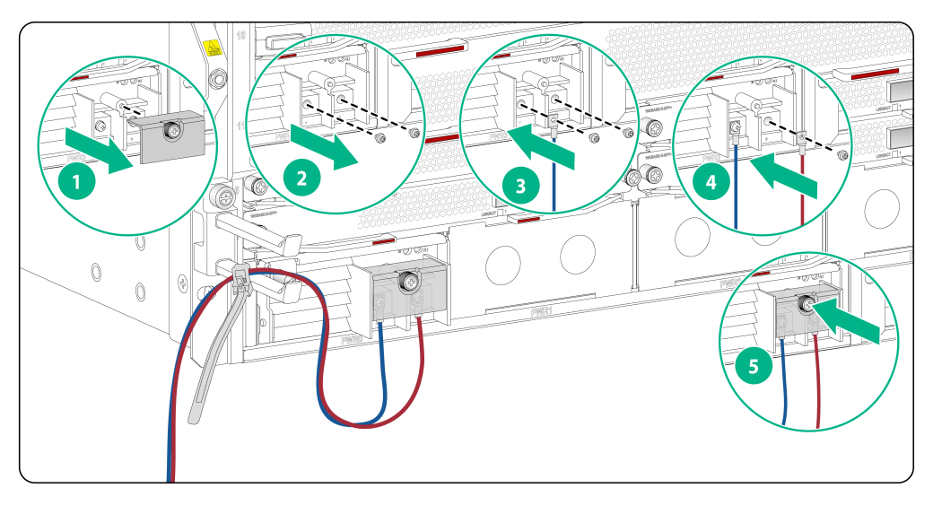
To connect a DC power cord to a PSR2400-D power supply:
1. As shown by callout 1 in Figure4-11, use a Phillips screwdriver to loosen the screw on the terminal protection cover and then remove the protection cover from the power supply.
2. As shown by callout 2 in Figure4-11, use a Phillips screwdriver to loosen the screws on the wiring terminals.
3. Connect the DC power cord to the power supply.
¡ As shown by callout 3 in Figure4-11, connect the wire marked with – to the negative terminal (–) on the power supply and fasten the screw.
¡ As shown by callout 4 in Figure4-11, connect the wire marked with + to the positive terminal (+) on the power supply and fasten the screw.
4. As shown by callout 5 in Figure4-11, place the protection cover over the wiring terminals and fasten the screw.
Figure4-11 Connecting the power cord for a PSR2400-D power supply
5. Connect the end of the DC power cord to a DC power source, with the wire marked with – connected to the terminal marked with –48V(–) and the wire marked with + connected to the terminal marked with RTN (+).
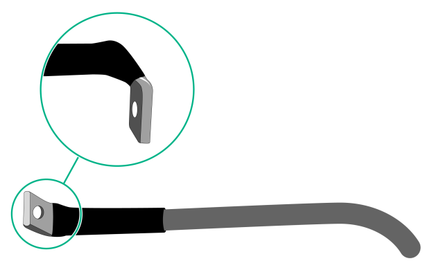
To use a one-hole lug for a power wire, use a heat-shrink tubing to cover the joint between the lug and the power wire and make sure the heat-shrink tubing wraps the root of the lug.
Figure4-12 Covering the joint with a heat-shrink tubing
Connecting an AC or HVDC power cord for a PSR2500B-12AHD-F power supply
|
|
CAUTION: · Do not use different types of power cords for the same router. · To use an AC power cord for the router, make sure the AC power cord has a straight connector. |
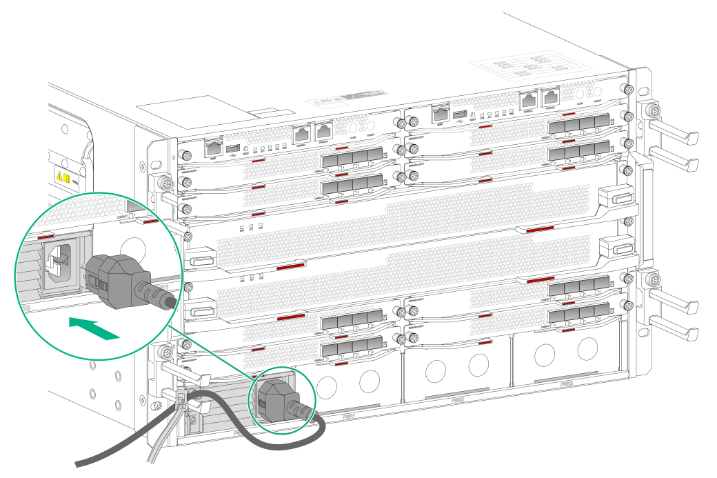
To connect an AC or HVDC power cord for a PSR2500B-12AHD-F power supply:
1. Insert the connector of the power cord to the power receptacle on the power supply, and use a cable tie to secure the power cord to the nearby cable management bracket.
2. Connect the other end of the power cord to a power source.
Figure4-13 Connecting an AC or HVDC power cord for a PSR2500B-12AHD-F power supply