- Table of Contents
-
- H3C CR16000-M Routers Installation Guide-5W102
- 00-Preface
- 01-Safety precautions
- 02-Preparing for installation
- 03-Installing the router
- 04-Installing removable components
- 05-Connecting cables
- 06-Verifying the installation
- 07-Starting and configuring the router
- 08-Replacement procedures
- 09-Troubleshooting
- 10-Appendix A Engineering labels
- 11-Appendix B Cable assembling and management
- 12-Appendix C Repackaging the Router
- Related Documents
-
| Title | Size | Download |
|---|---|---|
| 02-Preparing for installation | 835.73 KB |
Preparing the installation site
Unpacking and inspecting the router
Unpacking and inspecting the chassis
Unpacking and inspecting removable components
2 Preparing for installation
Preparing the installation site
Before installing the router, inspect and prepare the installation site to be sure that the router will work in a good operating environment. For the operating environment requirements of the router, see Generic Operating Environment Requirements of H3C Devices Installed Indoors.
Weight support
Make sure the floor or ground at the installation site can support the combined weight of the router and the rack. The total weight of the router includes the chassis and its components (for example, cards and power supplies) and accessories. For information about the weights of the router and its components, see H3C CR16000-M Routers Hardware Information and Specifications.
|
|
TIP: To assess the load-bearing requirements for the floor, take potential system expansion (for example, adding more cards) also in consideration. |
Temperature and humidity
|
|
CAUTION: If condensation occurs on the chassis after you move it from a lower temperature to a higher temperature, dry the chassis before powering it on to avoid short circuits. |
Adverse temperature and humidity conditions in the equipment room will accelerate the aging of devices and reduce the capability of the device to withstand harsh environment conditions.
· Lasting high relative humidity can cause poor insulation, electricity leakage, mechanical property change of materials, and metal corrosion.
· Lasting low relative humidity can cause washer contraction and ESD and bring issues including loose screws and circuit failure.
· High temperature can accelerate aging of insulation materials and significantly lower the reliability and lifespan of the router.
· Lasting high temperature and relative humidity can aggravate corrosion of corrosive gas and particles to the bare parts of the device and significantly reduce the service life of the device.
To prevent the preceding issues, maintain the temperature and humidity in the equipment room in the ranges as described in Table2-1.
Table2-1 Temperature and humidity requirements
|
Item |
Operating |
Storage |
|
Temperature |
0°C to 45°C (32°F to 113°F) |
–40°C to +70°C (–40°F to +158°F) |
|
Relative humidity |
5% to 95%, noncondensing |
5% to 95%, noncondensing |
Cleanliness
Dust buildup on the chassis might result in electrostatic adsorption, which causes poor contact of metal components and contact points. In the worst case, electrostatic adsorption can cause communication failure.
Table2-2 Dust concentration limits in the equipment room
|
Substance |
Concentration limit |
|
Dust particles (particle diameter ≥ 0.5 µm) |
≤ 1.8 × 10⁷ particles/m3 |
Harmful gas limit
Corrosive gases can accelerate corrosion and aging of components. Make sure the corrosive gases do not exceed the concentration limits as shown in Table2-3.
Table2-3 Corrosive gas concentration limits
|
Gas |
Average concentration (mg/m3) |
Maximum concentration (mg/m3) |
|
SO2 |
0.3 |
1.0 |
|
H2S |
0.1 |
0.5 |
|
Cl2 |
0.1 |
0.3 |
|
HCI |
0.1 |
0.5 |
|
HF |
0.01 |
0.03 |
|
NH3 |
1.0 |
3.0 |
|
O3 |
0.05 |
0.1 |
|
NOX |
0.5 |
1.0 |
EMI
All electromagnetic interference (EMI) sources, from outside or inside of the router and application system, adversely affect the router in the following ways:
· A conduction pattern of capacitance coupling.
· Inductance coupling.
· Electromagnetic wave radiation.
· Common impedance (including the grounding system) coupling.
To prevent EMI, use the following guidelines:
· If AC power is used, use a single-phase three-wire power receptacle with protection earth (PE) to filter interference from the power grid.
· Keep the router far away from radio transmitting stations, radar stations, and high-frequency devices.
· Use electromagnetic shielding, for example, shielded interface cables, when necessary.
· To prevent signal ports from getting damaged by overvoltage or overcurrent caused by lightning strikes, route interface cables only indoors.
Grounding
Using a good grounding system to protect your router against lightning shocks, interferences, and ESD is essential to the operating reliability of your router. For more information about grounding the router, see "Grounding the router."
Make sure the resistance between the chassis and the ground is less than 1 ohm.
Power supply
A good power supply system is essential for correct operation of the router. Make sure the power supply conditions and supplied power meet the router requirements.
Power supply conditions
The router supports AC, DC, HVDC, and battery power input. Make sure the equipment room provides the following power supply conditions:
· The AC power supply system is stable and reliable and capable of providing power required by the router. As a best practice, use two mains power sources for the AC power supply system. If only one mains is available in the equipment room, prepare a diesel generator as a backup power source.
· The DC power supply system is stable and reliable and the output voltage is stable and within the range required by the device.
· Enough batteries are available to ensure uninterrupted device operation in the event of a power failure.
Power
For the power supply system to provide power as required by the router:
1. Calculate the system power consumption.
The device supports multiple types of interfaces modules. The system power consumption varies by card type. For information about power consumptions of the system and its components, see H3C CR16000-M Routers Hardware Information and Specifications.
· Determine the number and type of power supplies based on the total power consumption of the router. Make sure the total maximum output power of the power supplies is greater than the total power consumption of the router. For information about the available power supplies, see H3C CR16000-M Routers Hardware Information and Specifications.
· Verify that the power supply system at the installation site is stable and provides power that meets the power supply specifications, including the rated input voltage and input current.
Cooling
Plan and build the ventilation system at the installation site carefully to ensure adequate cooling for the device. Make sure the following requirements are met:
· A minimum clearance of 10 cm (3.94 in) is reserved around the inlet and outlet air vents.
· The rack for the router has a good cooling system.
· The air conditioners do not blow air directly onto the router.
· The installation site has a good cooling system.
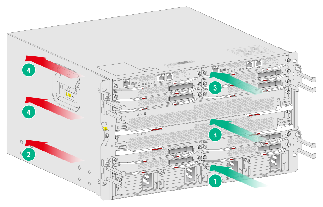
Figure2-1 demonstrates the airflow through the CR16000-M chassis.
Figure2-1 Airflow through the chassis (CR16000-M8)
|
(1) Direction of the airflow into the power supplies |
(2) Direction of the airflow out of the power supplies |
|
(3) Direction of the airflow into the chassis |
(4) Direction of the airflow out of the chassis |
Space
For easy installation and maintenance, follow these space requirements:
· Reserve a minimum clearance of 1 m (3.28 ft) between the rack and walls or other devices.
· For heat dissipation, make sure the headroom in the equipment room is not less than 3 m (9.84 ft).
· Make sure the rack has enough space to accommodate the router. See Table2-4 for rack requirements. For more information about chassis dimensions, see CR16000-M Routers Hardware Information and Specifications.
Table2-4 Router depth and rack requirements
|
Model |
Chassis depth |
Rack requirements |
|
CR16000-M8 CR16000-M16 |
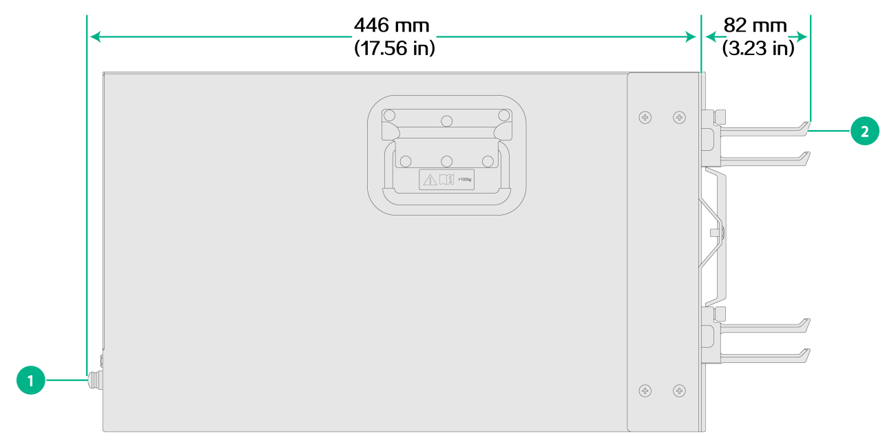
Total depth: 528 mm (20.79 in) · 82 mm (3.23 in) from the mounting surface of the mounting brackets to the front end of the cable management brackets · 446 mm (17.56 in) from the mounting surface of the mounting brackets to handles of the fan trays |
· A minimum depth of 0.6 m (1.97 ft) (recommended) · A minimum of 85 mm (3.35 in) between the front rack posts and the interior side of the front door (including the door lock and handle). · A minimum of 449 mm (17.68 in) between the front rack posts and the interior side of the rear door (including the door lock and handle). |
Figure2-2 demonstrates the depth of the CR16000-M router chassis.
Figure2-2 Chassis depth (CR16000-M8)
|
(1) Fan tray handle |
(2) Cable management bracket |
|
|
NOTE: · If the rack does not meet the requirements described in Table2-4, the rack door might fail to be closed after you install the router of standard configurations in the rack. · The signal cables and power cords are routed through the front of the chassis. If you use power cords that has a conductor cross-section area of a minimum of 16 sq mm (0.02 sq in), leave more space between the front rack posts and the front door as appropriate. |
Unpacking and inspecting the router
Pre-unpacking inspection
Before unpacking the router, perform basic pre-unpacking inspection with the presence of the two parties. Make sure the two parties sign for confirmation if all meet the requirements.
|
|
CAUTION: · Only qualified personnel can unpack and inspect the router. · Handle with care during device loading and unloading to prevent the device from being damaged by violent vibration or impact. · Arrange the packaging cartons in order, with the labels facing the same direction. · To avoid fatal damage to the device, do not place the packaging carton upside down. |
To perform pre-unpacking inspection:
1. Unload the shipment.
2. Check the shipment against the packing list and make sure you have received all items.
3. Verify that the packaging cartons are intact without any signs of damage or water soaking.
If any discrepancy or damage is found, do the following:
· Keep the device and its original packaging (including fillers and plastic bags) secure, and seal and archive the unpacking inspection records, photos of damaged goods, and photos of packaging and all label information on the packaging.
· The engineer on site fills in the cargo issue table within one working day and reports it to the H3C supply chain contact.
Unpacking and inspecting the chassis
1. Place the carton flat on the ground.
2. Use a utility knife to cut the straps on the carton. Open the carton and take the top foam cushion out of the carton.
Figure2-3 Opening the carton
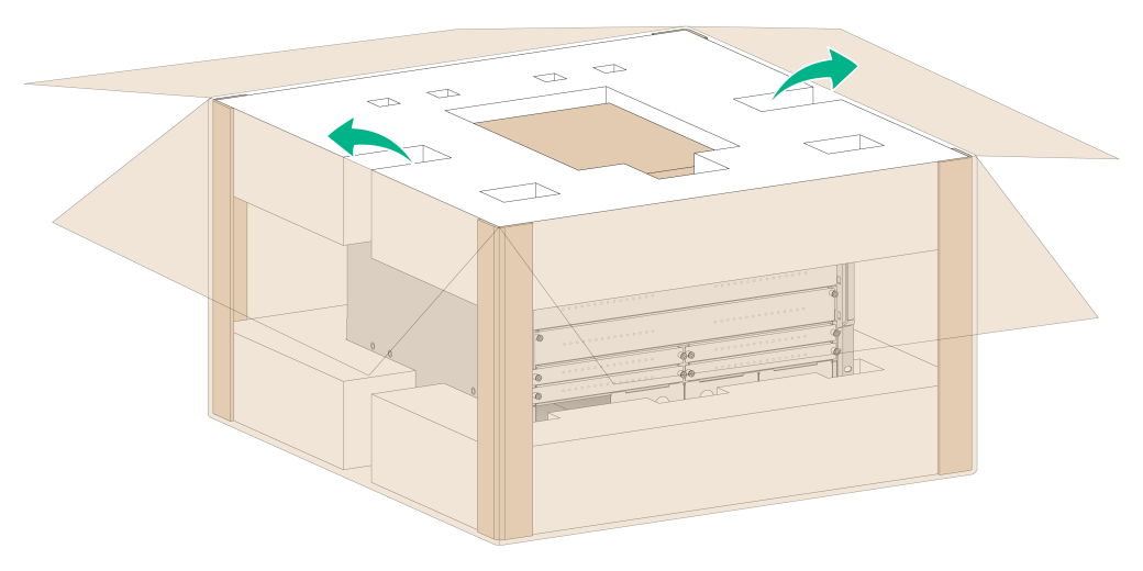
3. Take the chassis and its accessory boxes out from the carton and keep them secure.
4. Verify that the chassis is intact without any signs of water soaking or corrosion and the labels on the chassis are correct, clear, and complete.
5. Verify that the accessory box packaging is intact and not damaged. Check the accessories against the packing list to make sure you have received all accessories.
Unpacking and inspecting removable components
|
|
CAUTION: · To avoid ESD damages to electronic components, wear ESD gloves or an ESD wrist strap when handling a card and prevent any body contact with the electronic components. · After you take a card from a low temperature and dry place to a high temperature and wet place, wait 30 minutes before unpacking the carton to prevent card damage caused by moisture condensation. |
|
IMPORTANT: Check the components against the packing list and make sure you have received all components as ordered. |
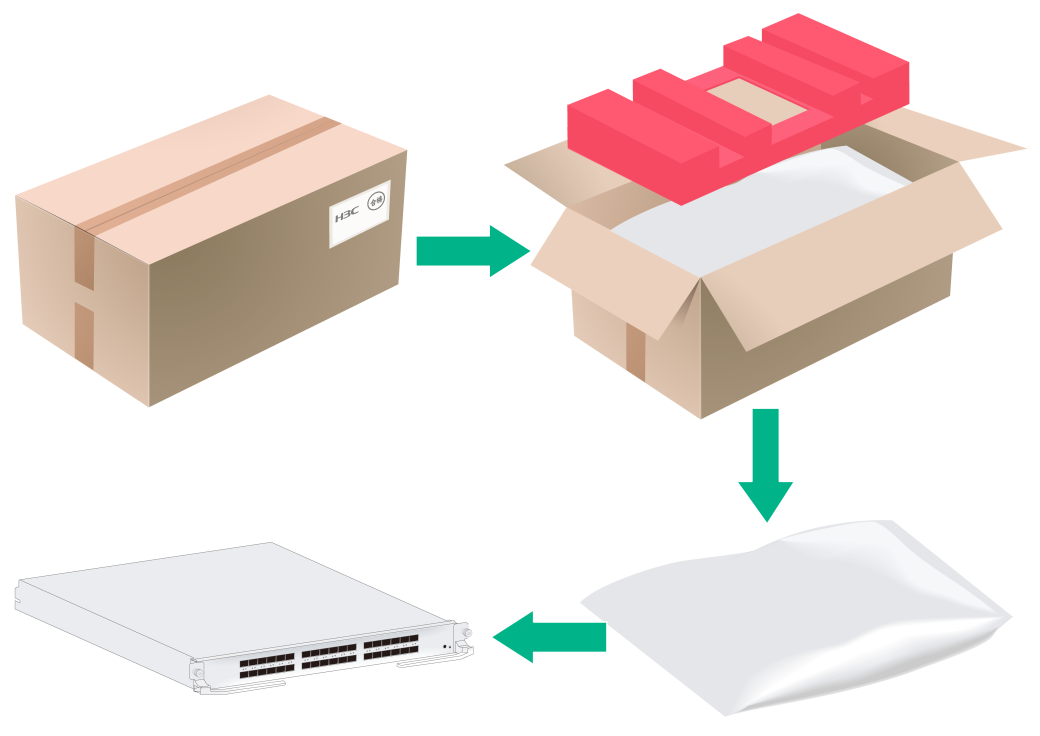
Typically, the removable components for the device such as cards and power supplies are packed and shipped in cartons. The packaging for the components includes cartons, shockproof foam, and anti-static bags.
To unpack and inspect a removable component:
1. Inspect the carton and make sure no water intrusion has occurred and the sealing labels are untampered.
2. Read the carton label and verify that the type and quantity of cards in the carton are as ordered.
3. Use a utility knife to cut the straps on the carton. Open the carton and take the top foam cushion out of the carton.
4. Wear an ESD wrist strap and make sure the wrist strap is reliably grounded.
5. Take the component out of the anti-static bag.
6. Inspect the component to be sure that they are good and intact.
Figure2-4 Unpacking a removable component
Inspecting cards
|
|
CAUTION: · To avoid card damage caused by sliding off or collision, do not stack unpacked cards for moving. · A card is vulnerable to ESD damages. To prevent ESD damages, see Generic Operating Environment Requirements of H3C Devices Installed Indoors. · Before installing a card, make sure the cabinet and chassis is clean and tidy. |
To inspect a card:
1. Wear an ESD wrist strap and make sure the wrist strap is reliably grounded.
2. Take the card out from the anti-static packaging carton.
3. Verify that the card name is consistent with that on the packaging carton.
4. Inspect the card for any damage and fall-off component.
5. Verify that the card connector is not damaged or blocked.
|
|
NOTE: A switching fabric module is provided with a protection box. To install the switching fabric module, first remove the protection box. · For a protection box that encloses the entire switching fabric module, loosen the captive screws on the box, open the ejector levers of switching fabric module, and then pull the card out. · For a protection box that encloses the rear half of the switching fabric module, loosen the captive screws on the box and then remove the protection box from the switching fabric module. |
Tools and equipment
No installation tools and equipment are provided with the router. Prepare installation tools and equipment yourself as required. The following tools and equipment are for your reference.
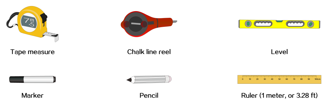
Measuring and marking tools
Figure2-5 lists the measuring and marking tools that you might use during installation.
Figure2-5 Measuring and marking tools
Drills
Figure2-6 lists the drills that you might use during installation.

Fastening tools
Figure2-7 lists the fastening tools that you might use during installation.
Figure2-7 Fastening tools

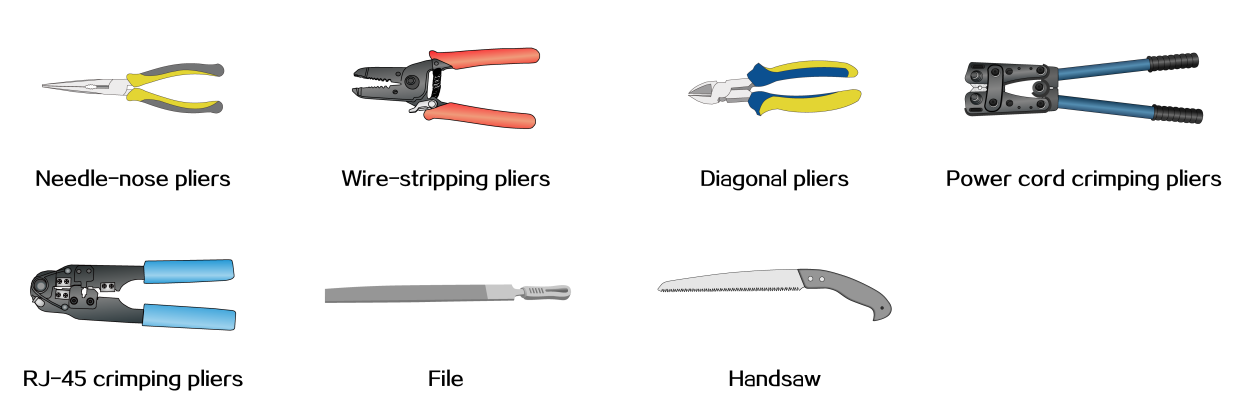
Fitter tools
Figure2-8 lists the fitter tools that you might use during installation.
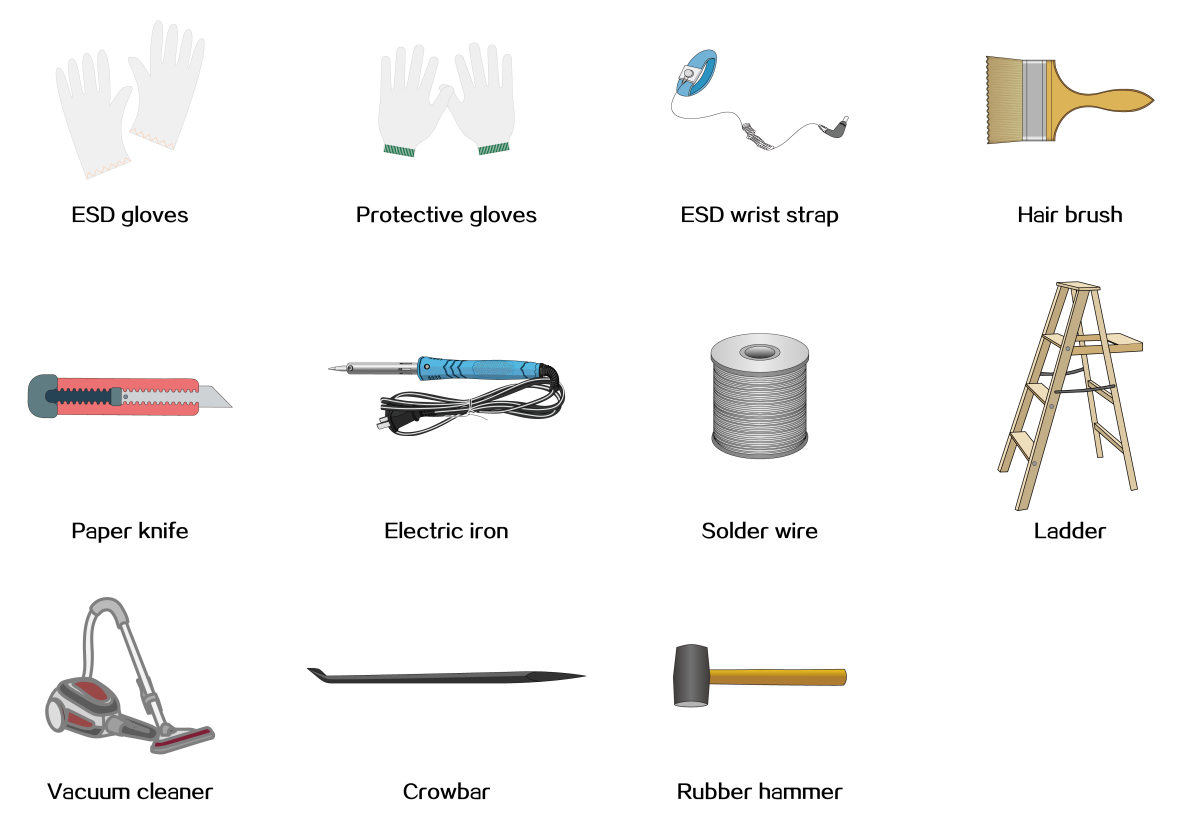
Auxiliary tools
Figure2-9 lists the auxiliary tools that you might use during installation.
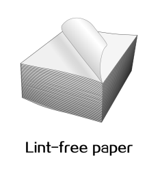
Fiber-optic cleaning tools
Figure2-10 lists the fiber-optic cleaning tools that you might use during installation.
Figure2-10 Fiber-optic cleaning tools
Equipment
Figure2-11 lists the equipment that you might use during installation.