- Table of Contents
-
- H3C CR16000-M Routers Installation Guide-5W102
- 00-Preface
- 01-Safety precautions
- 02-Preparing for installation
- 03-Installing the router
- 04-Installing removable components
- 05-Connecting cables
- 06-Verifying the installation
- 07-Starting and configuring the router
- 08-Replacement procedures
- 09-Troubleshooting
- 10-Appendix A Engineering labels
- 11-Appendix B Cable assembling and management
- 12-Appendix C Repackaging the Router
- Related Documents
-
| Title | Size | Download |
|---|---|---|
| 03-Installing the router | 772.47 KB |
Confirming installation preparations
Attaching slide rails and cage nuts to the rack
Mounting the router in the rack
Grounding the router with a grounding strip
Grounding the router through the PE wire of AC power supplies
Grounding the router through the RTN wire of DC power supplies
3 Installing the router
This section describes the procedure for installing the router.
|
|
NOTE: · The chassis and component views in this section are for illustration only. · Keep the packaging of the router and components, including the packaging cartons and bags, secure for future use. |
Confirming installation preparations
Before you install the router, verify the following requirements are met:
· You have read the chapter "Preparing for installation" carefully and the installation site meets all the requirements.
· A 19-inch rack is ready for use if you are to install the router in a rack. For information about how to install a rack, see the rack installation guide.
· The rack is sturdy and is reliably grounded.
· No debris or obstacles exist inside or around the rack.
· The rack has enough space to accommodate the router. As a best practice to maintain the rack stability, install the router at the rack bottom. To mount multiple devices in a rack, install the heavier devices at the bottom.
· The total height of the devices to be installed is no higher than the available installation height of the rack and enough clearance is reserved for cable routing.
· The router is ready for installation and has been carried to a place near the rack and convenient for moving.
Attaching slide rails and cage nuts to the rack
Installing slide rails
Before you mount the router in a rack, install slide rails on the rack. As a best practice, purchase slide rails from H3C. For information about the slide rails recommended for the router, see H3C CR16000-M Routers Hardware Information and Specifications. For information about installing the slide rails, see the installation guide shipped with the slide rails.
If the rack has slide rails installed, skip this section.
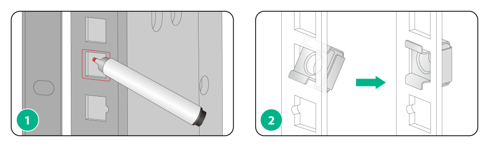
Installing cage nuts
Before mounting the chassis in the rack, attach cage nuts to the front rack posts.
1. Determine the installation holes for cage nuts based on the mounting holes in the mounting brackets and the installation position of the slide rails.
You can use a reference (such as a tape measure) to record the installation holes of the mounting brackets and mark the cage nut holes on the rack posts accordingly.
2. Install cage nuts into the marked square holes on the front rack posts.
Figure3-1 Installing cage nuts
Mounting the router in the rack
|
|
WARNING! · Do not hold the handle of a fan tray or power supply, air vents, or the handle on the real panel to move the router. Doing so might cause equipment damage or even bodily injury. · The router is heavy. As a best practice, use a mechanical lift to move it. · After placing the router on the slide rails, do not leave go of your hands immediately because this might tip the router, damaging the router or even causing bodily injury. |
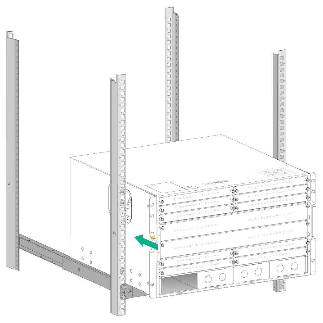
To mount the router in the rack:
1. Orient the chassis with its rear facing the front of the rack.
2. Use a minimum of four people to lift the router by using the handles or supporting the bottom of the chassis until the bottom of the router is a little higher than the slide rails on the rack.
3. Place the router on the slide rails and slide the router along the slide rails until the mounting brackets on the router are flush against the front rack posts.
Figure3-2 Mounting the chassis on the slide rails
4. Attach the chassis to the rack with mounting screws.
Figure3-3 Mounting the chassis in the rack
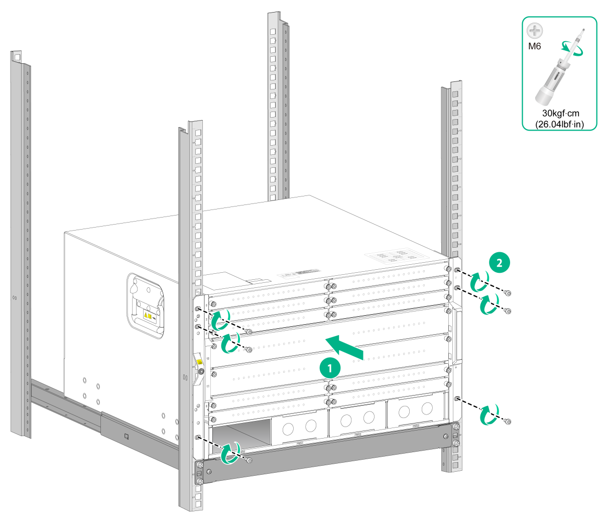
If the mounting holes in the mounting brackets cannot align with the cage nuts on the rack, verify that the bottom edge of the slide rail aligns with the middle of the narrower metal area between holes and that the cage nuts are installed in the correct holes.
Grounding the router
|
|
CAUTION: Reliably grounding the router is crucial to lightning protection and EMI protection. Ground the router reliably before you use it. |
Grounding the router with a grounding strip
|
|
CAUTION: · To guarantee the grounding effect, use the grounding cable (yellow-green grounding cable) provided with the router to ground the router. · Connect the grounding cable to the grounding system in the equipment room. Do not connect it to a fire main or lightning rod. |
If a grounding strip is available at the installation site, ground the router by connecting the grounding cable to the grounding strip.
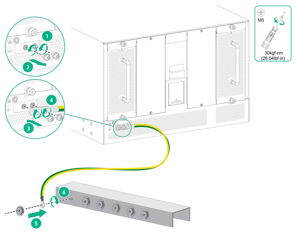
1. Unpack the grounding cable.
The grounding cable provided with the router is compliant with the NEBS standards, with a dual-hole grounding lug at one end for connecting to the chassis and a ring terminal at the other end for connecting the grounding strip.
2. As shown by callouts 1 and 2 in Figure3-4, remove the grounding screws from the grounding holes at the rear of the chassis.
3. As shown by callouts 3 and 4 in Figure3-4, use the grounding screws to attach the dual-hole grounding lug of the grounding cable into the grounding holes of the chassis.
4. As shown by callouts 5 and 6 in Figure3-4, connect the ring terminal of the grounding cable to a grounding post on the grounding strip, and fasten the grounding cable to the grounding post with the hex nut.
Figure3-4 Connecting the grounding cable to a grounding strip
Grounding the router through the PE wire of AC power supplies
|
|
CAUTION: Make sure the AC power supply uses a three-wire cable with a protection wire, and the PE wire of the AC power supply is correctly grounded at the power distribution room or AC power supply transformer side. In addition, make sure the PE terminal on the router is correctly connected to the PE wire of the AC power supply. |
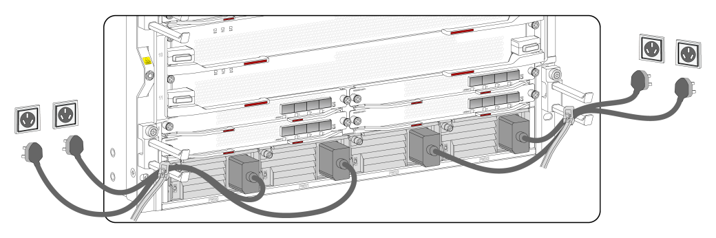
If the router is AC powered and no grounding strip is available at the installation site, you can ground the router through the PE wire of the AC power supply, as shown in Figure3-5.
Figure3-5 Grounding the router through the PE wire of AC power supplies
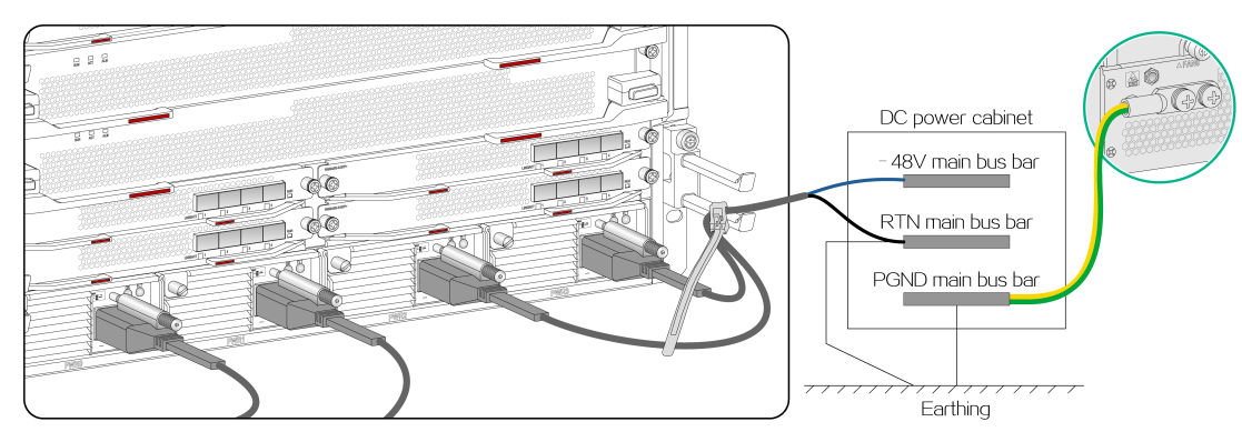
Grounding the router through the RTN wire of DC power supplies
|
|
CAUTION: Make sure the RTN wire is grounded reliably when it is routed out from the DC power cabinet. |
If the router is powered by a –48 VDC power supply and no grounding strip is available at the installation site, you can ground the router through the return (RTN) wire of the DC power supplies, as shown in Figure3-6.
Figure3-6 Grounding the router through the RTN wire of the DC power supplies