- Table of Contents
-
- H3C CR16000-M Routers Installation Guide-5W102
- 00-Preface
- 01-Safety precautions
- 02-Preparing for installation
- 03-Installing the router
- 04-Installing removable components
- 05-Connecting cables
- 06-Verifying the installation
- 07-Starting and configuring the router
- 08-Replacement procedures
- 09-Troubleshooting
- 10-Appendix A Engineering labels
- 11-Appendix B Cable assembling and management
- 12-Appendix C Repackaging the Router
- Related Documents
-
| Title | Size | Download |
|---|---|---|
| 08-Replacement procedures | 1.35 MB |
Contents
Replacing an MPU/interface module
Replacing a switching fabric module
Replacing a transceiver module
Replacing a transceiver module
8 Replacement procedures
|
WARNING! · Ensure electricity safety when you replace a removable component on an operating router. · To avoid device damage and bodily injury, strictly follow the replacement procedures to replace removable components on the router. |
The router uses a modular architecture. You can replace removable components on an operating router.
Replacing a power supply
Precautions
Before you replace a power supply, read the following precautions carefully:
· To avoid device damage or bodily injury, strictly follow the procedures shown in Figure8-1 and Figure8-2 to replace a power supply.
· Do not install power supplies of different models on the same router.
· Prepare a circuit breaker for each power supply. Before replacing a power supply, turn off its circuit breaker.
· The power supply might be of high temperature. Remove it with caution.
· To reinstall the removed power supply, wait for its status LEDs to turn off.
· If you are not to install a new power supply after removing the old one, install a filler panel in the slot.
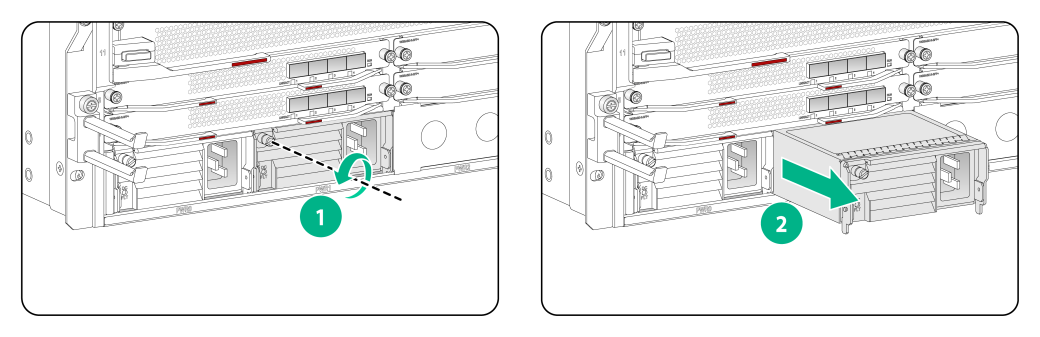
Figure8-1 Power supply removal flowchart
![]()
Figure8-2 Power supply installation flowchart
![]()
Procedure
1. Prepare an antistatic mat to place the removed power supply.
2. Turn off the circuit breaker.
3. Wear an ESD wrist strap and make sure it makes good skin contact and is correctly grounded. For more information, see "Attaching an ESD wrist strap."
4. Remove the power cord from the power supply:
¡ AC power cord—Remove the cable tie from the power cord, and then remove the power cord connector from the power supply.
¡ DC power cord from a PSR2400-12D power supply—Remove the cable tie from the power cord, loosen the fastening screw on the power cord, and then remove the power cord connector from the power supply.
¡ DC power cord from a PSR2400-D power supply—Remove the cable tie from the power cord, remove the protection cover over the wiring terminals, remove the screws on the wiring terminals, and then remove the power cord lugs.
5. As shown by callout 1 in Figure8-3, use a Phillips screwdriver to loosen the captive screw on the power supply, and then grasp the captive screw between your thumb and index finger to carefully pull out the handle of the power supply.
6. As shown by callout 2 in Figure8-3, holding the power supply handle with one hand and supporting the bottom of the power supply with the other, gently pull the power supply out.
7. Put the removed power supply on the antistatic mat.
8. Install a new power supply. For the installation procedures, see "Installing a power supply."
Figure8-3 Removing a power supply (AC power supply)
Replacing an MPU/interface module
|
|
CAUTION: · Power off the router before removing the only MPU running on the router. · To replace an MPU or interface module, first remove all its cables. |
The router supports hot swapping of MPUs and interface modules. You can replace an MPU or interface module when the router is operating.
The replacement procedure is the same for the MPUs and interface modules. The following procedure uses an MPU as an example.
1. Prepare an antistatic mat to place the removed card.
2. Wear an ESD wrist strap and make sure it makes good skin contact and is correctly grounded. For more information, see "Attaching an ESD wrist strap."
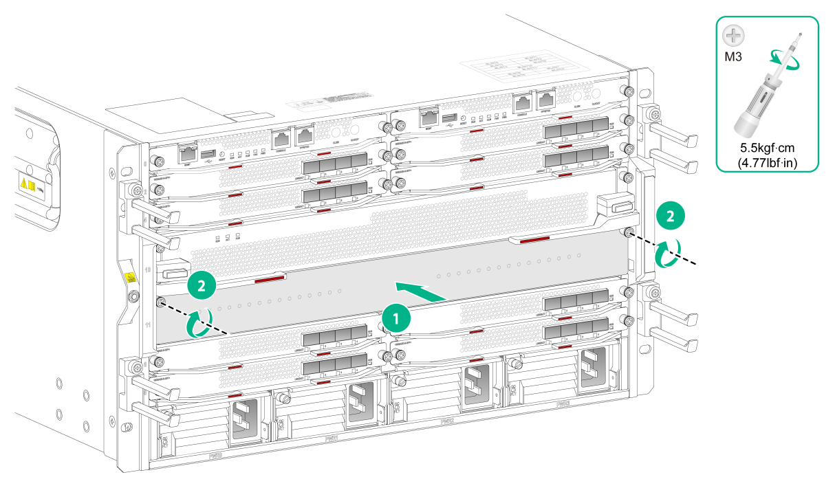
3. As shown by callout 1 in Figure8-4, use a Phillips screwdriver to loosen the captive screws on the card.
4. As shown by callout 2 in Figure8-4, rotate the ejector levers outwards to separate the card from the backplane.
5. As shown by callout 3 in Figure8-4, use one hand to slowly move the card outwards. Supporting the bottom of the card with the other, pull the card out of the slot along slide rails.
6. Put the removed card on the antistatic mat.
7. Install a new card. For the installation procedure, see "Installing MPUs/interface modules."
8. If you are not to install a new card, install a filler panel in the slot to ensure adequate ventilation and prevent dust.
Figure8-4 Removing an MPU
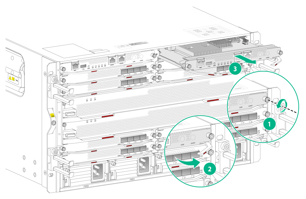
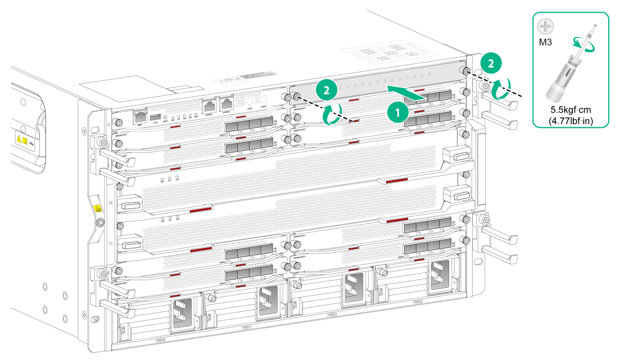
Figure8-5 Installing a filler panel in an unused MPU slot
Replacing a switching fabric module
1. Prepare an antistatic mat to place the removed switching fabric module.
2. Put on an ESD wrist strap, and make sure the wrist strap makes good skin contact and is reliably grounded. For more information, see "Attaching an ESD wrist strap."
3. As shown by callout 1 in Figure8-6, use a Phillips screwdriver to loosen the captive screws on the switching fabric module.
4. As shown by callout 2 in Figure8-6, press the ejector buttons on the ejector levers to release the ejector levers.
5. As shown by callout 3 in Figure8-6, rotate outward the ejector levers of the card to separate the card connector from the backplane.
6. As shown by callout 4 in Figure8-6, use one hand to slowly move the card outwards. Supporting the bottom of the card with the other hand, pull the card out of the slot along slide rails.
7. Put the removed card on the antistatic mat.
8. Install a new switching fabric module. For the installation procedure, see "Installing switching fabric modules."
9. If you are not to install a new switching fabric module, install a filler panel in the switching fabric module slot to ensure adequate ventilation and prevent dust.
Figure8-6 Removing a switching fabric module
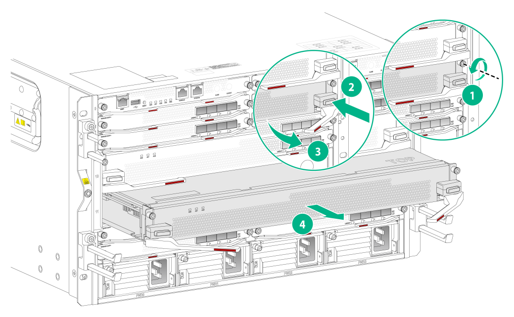
Figure8-7 Installing a filler panel in an unused switching fabric module slot
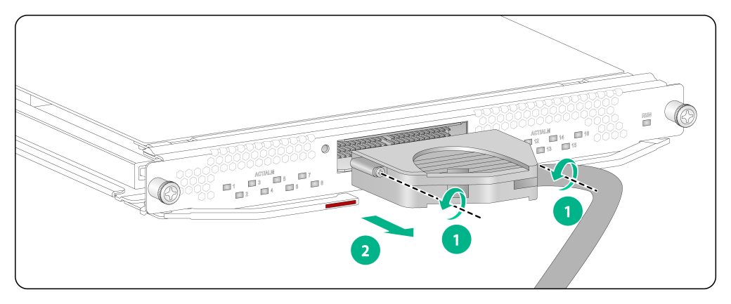
Replacing a fan tray
|
|
WARNING! To avoid bodily injury, do not touch the rotating fans when replacing a fan tray. |
If a fan tray fails, replace it immediately to ensure adequate heat dissipation of the router.
1. Prepare an antistatic mat to place the fan tray to be removed.
2. Put on an ESD wrist strap and make sure the wrist strap makes good skin contact and is correctly grounded. For more information, see "Attaching an ESD wrist strap."
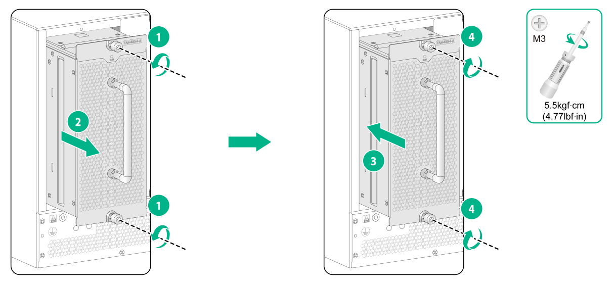
3. As shown by callout 1 in Figure8-8, loosen the captive screws on the fan tray.
4. As shown by callout 2 in Figure8-8, hold the handle of the fan tray with one hand to gently pull the fan tray part way out of the chassis. After the fans stop rotating, support the bottom of the fan tray with the other hand, and take out the fan tray from the chassis.
5. Put the removed fan tray on the antistatic mat.
6. Unpack the fan tray to be installed.
7. As shown by callout 3 in Figure8-8, holding the handle of the fan tray with one hand and supporting bottom with the other, gently slide the fan tray along the guide rails into the slot until it is firmly secured in the slot.
8. As shown by callout 4 in Figure8-8, fasten the captive screws on the fan tray.
Figure8-8 Replacing a fan tray
Replacing a transceiver module
|
|
WARNING! Disconnected optical fibers or transceiver modules might emit invisible laser light. Do not stare into beams or view directly with optical instruments when the router is operating. |
|
|
CAUTION: · Do not touch the golden plating on a transceiver module during the replacement process. · Make sure the new transceiver module is the same model as the peer transceiver module at the other end of the optical fiber. · If you are not to insert a transceiver module into a fiber port, insert the dust plug provided with the module into the port to prevent foreign object intrusion. |
|
|
NOTE: In case of limited space, you can use tweezers or other tools to remove a transceiver module or optical fiber. |
Replacing a transceiver module
1. Wear an ESD wrist strap and make sure it makes good skin contact and is correctly grounded.
For more information, see "Attaching an ESD wrist strap."
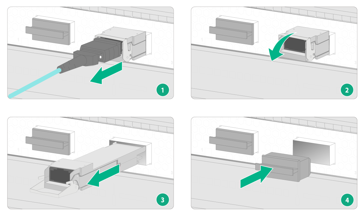
2. Remove the optical fibers from the module.
There is a latching mechanism between a fiber connector and transceiver module bore to prevent connector disengagement. Release the latching mechanism before removing the optical fiber. To avoid damages, do not use excessive force.
¡ To remove optical fibers with an LC connector, press the clip on the connector to pull the LC connector out of the port, as shown in Figure8-9.
¡ To remove an optical fiber with an MPO connector, hold the front end of the MPO connector and then pull it out of the port, as shown in Figure8-10.
3. Pivot the bail latch down to the horizontal position.
4. Hold the bail latch to pull the module out of the slot. Make sure you apply force in the direction parallel to the ground. To avoid damaging the bail latch, do not use excessive force.
If you apply force at an angle when pulling the module out, you can hardly pull the module out and the module or fiber port might be damaged.
5. Insert the dust plug into the removed module, and put the module into its packaging bag.
6. Install a new module. For the installation procedure, see "Installing a transceiver module and connecting optical fibers."
Figure8-9 Removing a transceiver module (LC interface)
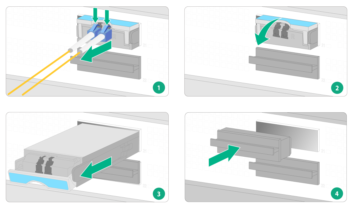
Figure8-10 Removing a transceiver module (MPO interface)
Replacing an E1 cable
1. Wear an ESD wrist strap and make sure it makes good skin contact and is reliably grounded.
For more information, see "Attaching an ESD wrist strap."
2. Use a screwdriver to loosen the screws on the connector of the E1 cable.
3. Pull out the E1 cable slowly.
Figure8-11 Removing an E1 cable
4. Install a new E1 cable.
For the installation procedure, see "Connecting an E1 cable."
