- Table of Contents
-
- H3C S10500 Switch Series Installation Guide-6W208
- 00-Preface
- 01-Chapter 1 Preparing for Installation
- 02-Chapter 2 Installing the Switch
- 03-Chapter 3 Installing FRUs
- 04-Chapter 4 Connecting Your Switch to the Network
- 05-Chapter 5 Replacement Procedures
- 06-Chapter 6 Troubleshooting
- 07-Appendix A Chassis Views and Technical Specifications
- 08-Appendix B FRUs and Compatibility Matrixes
- 09-Appendix C LEDs
- 10-Appendix D Cables
- 11-Appendix E Engineering Labels
- 12-Appendix F Cable Management
- 13-Appendix G Repackaging the Switch
- Related Documents
-
| Title | Size | Download |
|---|---|---|
| 09-Appendix C LEDs | 295.12 KB |
9 Appendix C LEDs
Table 9-1 LEDs at a glance
|
LEDs |
|
|
· Management Ethernet port LEDs |
|
|
Base card LEDs |
|
|
Subcard LEDs |
|
MPU LEDs
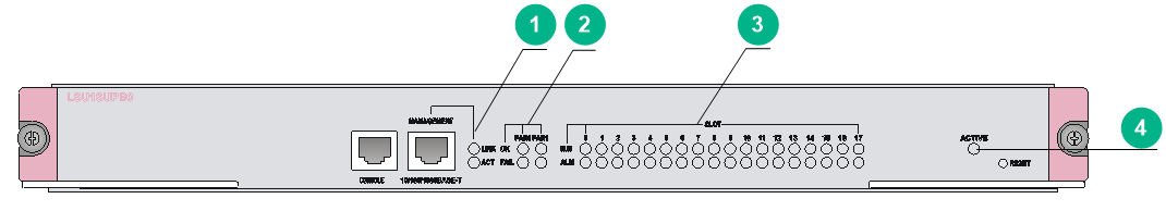
LEDs on the LSU1SUPA0, LSU1SUPB0, and LSUM1SUPD0 MPUs are similar. Figure 9-1 uses the LSU1SUPB0 MPU as an example.
Figure 9-1 LEDs on the LSU1SUPB0 MPU
|
(1) Management Ethernet port LEDs |
(2) Fan tray status LEDs |
|
(3) Card status LEDs |
(4) MPU active/standby status LED |
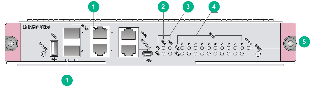
The LEDs on the LSUM1SUPC0, LSUM1MPU06B0, LSUM1MPU10A0, and LSUM1MPU10C0 MPUs are similar. Figure 9-2 uses the LSUM1MPU06B0 MPU as an example.
Figure 9-2 LEDs on the LSUM1MPU06B0 MPU
|
(1) Management Ethernet port LEDs |
(2) Fan tray status LEDs |
|
(3) Power module status LEDs |
(4) Service module status LEDs |
|
(5) MPU active/standby status LED |
|
Management Ethernet port LEDs
The LSU1SUPA0, LSU1SUPB0, LSUM1SUPC0, and LSUM1SUPD0 MPUs use a pair of LEDs LINK and ACT to indicate the link and data forwarding status of a management Ethernet port.
Table 9-2 Management Ethernet port LED description for the LSU1SUPA0, LSU1SUPB0, LSUM1SUPC0, and LSUM1SUPD0 MPUs
|
LINK LED status |
ACT LED status |
Description |
|
On |
Flashing |
A link is present, and the management Ethernet port is receiving or sending data. |
|
On |
Off |
A link is present. |
|
Off |
Off |
No link is present. |
The LSUM1MPU06B0, LSUM1MPU10A0, and LSUM1MPU10C0 MPUs use a LINK/ACT LED to indicate the link and data forwarding status of a management Ethernet port.
Table 9-3 Management Ethernet port LED description for the LSUM1MPU06B0 and LSUM1MPU10C0 MPUs
|
LINK/ACT LED Status |
Description |
|
Flashing green |
A link is present, and the management Ethernet port is receiving or sending data. |
|
Steady green |
A link is present. |
|
Off |
No link is present. |
Fan tray status LEDs
The LSU1SUPA0, LSU1SUPB0, LSUM1SUPC0, and LSUM1SUPD0 MPUs provide a pair of LEDs OK and FAIL for each of the two fan trays (FAN0 and FAN1).
The LSUM1MPU06B0, LSUM1MPU10A0, and LSUM1MPU10C0 MPUs provide a pair of FAN LEDs OK and FAIL to indicate the status of the fan tray.
Table 9-4 Fan trays for different models of the S10500
|
Chassis model |
Fan tray |
Fan tray quantity |
|
· S10504 · S10508 · S10508-V |
FAN0 |
1 |
|
· S10506 · S10510 |
FAN |
1 |
|
S10512 |
FAN0 and FAN1 |
2 |
Table 9-5 Fan tray LED description
|
OK LED status |
FAIL LED status |
Description |
|
On |
Off |
The fan tray is operating correctly. |
|
Off |
On |
A fan problem is present or the fan tray is not in position. |
|
Off |
Off |
The switch is not powered on. |
Power status LEDs
The LSUM1SUPC0, LSUM1MPU06B0, LSUM1MPU10A0, and LSUM1MPU10C0 MPUs provide a pair of PWR LEDs OK and FAIL to indicate the status of the power modules.
Table 9-6 Power status LED description
|
OK LED status |
FAIL LED status |
Description |
|
On |
Off |
The power modules are operating correctly. |
|
Off |
On |
A power module problem is present or a power module is not in position. |
|
Off |
Off |
The switch is not powered on. |
Card LEDs
Each MPU has the LEDs numbered the same as card slots to indicate the status of the active MPU, standby MPU, service modules, and switching fabric modules in the slots. Table 9-7 shows the LED description.
|
|
NOTE: Slot numbers are marked on top of the slots on the S10508-V switch and on the right of the slots on other S10500 switches. |
Table 9-7 Card LED description
|
RUN LED status |
ALM LED status |
Description |
|
Flashing (0.5 Hz) |
Off |
The card is operating correctly. |
|
Flashing (4 Hz) |
On |
The service module or switching fabric module is loading software. If the LED flashes continuously, the software version of the switch does not match that of the card. |
|
Flashing (0.5 Hz) |
Flashing (0.25 Hz) |
The card temperature exceeds the upper warning threshold or falls below the lower warning threshold. |
|
On |
On |
The card is booting or faulty. |
|
On |
Off |
The MPU is starting up. |
|
Off |
Off |
The card is not in position. |
|
|
NOTE: · When the RUN LED flashes 4 times per second, the card is loading software. If the RUN LED flashes in this state continuously, the card is not compatible with the switch software. · Before the active MPU starts up, all card LEDs are off. The tables describe the card LED status after the active MPU starts up. · The ALM LED for a service module lights for a period of time at the initial phase of the system startup. |
MPU active/standby status LED
Each MPU has one ACTIVE LED to indicate the active or standby status of the MPU.
Table 9-8 MPU ACTIVE LED description
|
Status |
Description |
|
On |
The MPU is active. |
|
Off |
· The MPU is in standby status. · The MPU is faulty. Examine the card LED for an MPU problem. |
QSFP+ port LED
The LSUM1MPU10A0 MPU provides a QSFP+ port LED for each QSFP+ port to indicate the link and data sending and receiving status of the port.
Table 9-9 QSFP+ port status LED description
|
Status |
Description |
|
Flashing |
The port is sending or receiving data. |
|
On |
A link is present on the port. |
|
Off |
No link is present on the port. |
Service module LEDs
RJ-45 Ethernet port LED
Table 9-10 RJ-45 Ethernet port LED description
|
LED status |
Description |
|
Flashing yellow |
The Ethernet port is receiving or sending data at 100/1000 Mbps. |
|
Flashing green |
The Ethernet port is receiving or sending data at 10 Gbps. |
|
Steady yellow |
A 100/1000 Mbps link is present. |
|
Steady green |
A 10 Gbps link is present. |
|
Off |
No link is present. |
SFP port LED
Table 9-11 SFP port LED description
|
Status |
Description |
|
Flashing |
The SFP port is receiving or sending data. |
|
On |
A link is present. |
|
Off |
No link is present. |
SFP+ port LED
The service modules provide one SFP+ port LED for each SFP+ port to indicate the link status and data receiving/forwarding status of the SFP+ ports.
Table 9-12 SFP+ port LED description
|
Status |
Description |
|
Flashing yellow |
The SFP+ port is receiving or sending data at 100/1000 Mbps. |
|
Flashing green |
The SFP+ port is receiving or sending data at 10 Gbps. |
|
Steady yellow |
A 100/1000 Mbps link is present. |
|
Steady green |
A 10 Gbps link is present. |
|
Off |
No link is present. |
SPF28 port LED
The service modules provide one SFP28 port LED for each SFP28 port to indicate the link status and data receiving/forwarding status of the SFP28 ports.
Table 9-13 SFP28 port LED description
|
Status |
Description |
|
Flashing |
The SFP28 port is receiving or sending data. |
|
On |
A link is present. |
|
Off |
No link is present. |
XFP port LEDs
Table 9-14 XFP port LED description
|
LINK LED status |
ACT LED status |
Description |
|
On |
Flashing |
A link is present, and the XFP port is receiving or sending data. |
|
On |
Off |
A link is present, but no data is being received or sent. |
|
Off |
Off |
No link is present. |
QSFP+ port LED
The service modules provide a LED for each QSFP+ port to indicate the link status and data receiving/forwarding status of the QSFP+ ports.
Table 9-15 QSFP+ port LED description
|
Status |
Description |
|
Flashing |
The QSFP+ port is receiving or sending data. |
|
On |
A link is present, but no data is being received or sent. |
|
Off |
No link is present. |
|
|
NOTE: The color of the QSFP+ port LED indicates support of the port for 100-GE/40-GE switchover as follows: · Yellow—The port supports 100-GE/40-GE switchover. · Green—The port does not support 100-GE/40-GE switchover.. |
QSFP28 port LED
The service modules provide a LED for each QSFP28 port to indicate the link status and data receiving/forwarding status of the QSFP28 ports.
Table 9-16 QSFP28 port LED description
|
Status |
Description |
|
Flashing |
The QSFP28 port is receiving or sending data. |
|
On |
A link is present, but no data is being received or sent. |
|
Off |
No link is present. |
|
|
NOTE: The color of the QSFP28 port LED indicates the port speed as follows: · Green—100 Gbps. · Yellow—Less than 100 Gbps. |
CFP port LED
The service modules provide a LED for each CFP port to indicate the link status and data receiving/forwarding status of the CFP ports.
Table 9-17 CFP port LED description
|
Status |
Description |
|
Flashing |
The CFP port is receiving or sending data. |
|
On |
A link is present, but no data is being received or sent. |
|
Off |
No link is present. |
Switching fabric module LEDs
The switching fabric module has one RUN LED and one ALM LED to indicate its operating status.
Table 9-18 Switching fabric module LED description
|
RUN LED status |
ALM LED status |
Description |
|
Flashing (0.5 Hz) |
Off |
The switching fabric module is operating correctly. |
|
Off |
On |
The switching fabric module is faulty. |
|
Flashing (0.5 Hz) |
On |
The temperature of the switching fabric module has exceeded the upper or lower limit. |
|
Off |
Off |
The switching fabric module has not started. |
|
On |
Off |
The switching fabric module is up. |
Fan tray status LEDs
The fan trays for the S10500 switches have one OK LED and one FAIL LED to indicate its operating status.
Table 9-19 Fan tray LED description
|
OK LED status |
FAIL LED status |
Description |
|
On |
Off |
The fan tray is operating correctly. |
|
Off |
On |
The fan tray is faulty. |
|
Off |
Off |
The fan tray is not powered on. |
Power module LEDs
The LSUM1AC1200 and LSUM2AC2500 power modules each have one AC LED and one DC LED to indicate the operating status. The LSUM1DC2400 power module has one INP OK LED and one DC/FLT LED to indicate its operating status.
Table 9-20 LSUM1AC1200 and LSUM1AC2500 power module LED description
|
LED |
Color |
Description |
|
AC |
Off |
· The power module has no power input. · The input voltage is too low, and the power module is in self protection state. |
|
Green |
The power input is normal. |
|
|
DC |
Green |
The power module is outputting power normally. |
|
Red |
The power module is experiencing an output problem, including output short-circuit, output overcurrent, output overvoltage, input under-voltage, or remote power off, and has entered the self protection state. |
|
|
Orange |
The power module is in an over-temperature condition and has entered the self protection state. |
Table 9-21 LSUM1DC2400 power module LED description
|
LED |
Color |
Description |
|
INP OK |
Off |
· The power module has no power input. · The input voltage is too low, and the power module is in self protection state. |
|
Green |
The power input is normal. |
|
|
DC/FLT |
Green |
The power module is outputting power normally. |
|
Red |
The power module is experiencing an output problem, including output short-circuit, output overcurrent, output overvoltage, input under-voltage, or remote power off, and has entered the self protection state. |
|
|
Orange |
The power module is in an over-temperature condition and has entered the self protection state. |
PoE module status LEDs
PoE power module LEDs
Table 9-22 PoE module LED description
|
LED |
Status |
Description |
|
Input power |
Steady green |
The power input is normal. |
|
Off |
No power is being input. |
|
|
Flashing green |
The power input has exceeded the upper limit. |
|
|
Output power |
Steady green |
The power output is normal. |
|
Off |
No power is being output. |
|
|
Flashing green |
The power output has exceeded the upper limit. |
|
|
Temperature alarm |
Steady yellow |
The temperature of the module has reached the alarm threshold. |
|
Off |
The PoE power module is operating correctly. |
|
|
Power module failure |
Steady red |
The PoE power module is faulty. |
|
Off |
The PoE power module is operating correctly. |
PoE monitoring module LEDs
Table 9-23 PoE monitoring module LED description
|
LED |
Status |
Description |
|
RUN |
Steady green |
The PoE monitoring module is operating correctly. |
|
Off |
The PoE monitoring module is faulty. |
|
|
MAJOR |
Steady red |
One of the following events might occur: · The PoE power module is faulty. · All PoE power modules are removed. · The switch on the PoE power frame is off. · The PoE power module is present but no AC power is being input. |
|
On and then off |
The PoE power module hot swapping has been performed. |
|
|
Off |
The PoE power module is operating correctly. |