- Table of Contents
-
- H3C S10500 Switch Series Installation Guide-6W208
- 00-Preface
- 01-Chapter 1 Preparing for Installation
- 02-Chapter 2 Installing the Switch
- 03-Chapter 3 Installing FRUs
- 04-Chapter 4 Connecting Your Switch to the Network
- 05-Chapter 5 Replacement Procedures
- 06-Chapter 6 Troubleshooting
- 07-Appendix A Chassis Views and Technical Specifications
- 08-Appendix B FRUs and Compatibility Matrixes
- 09-Appendix C LEDs
- 10-Appendix D Cables
- 11-Appendix E Engineering Labels
- 12-Appendix F Cable Management
- 13-Appendix G Repackaging the Switch
- Related Documents
-
| Title | Size | Download |
|---|---|---|
| 03-Chapter 3 Installing FRUs | 3.85 MB |
Setting up a PoE system (optional)
Connecting an external PoE power frame
(Optional) Installing transceiver modules and network cables
Installing transceiver modules
3 Installing FRUs
There is no required order for installing FRUs. As a best practice, connect power cords after completing installing all required FRUs.
|
|
TIP: Keep the chassis and the component packages for future use. |
Attaching an ESD wrist strap
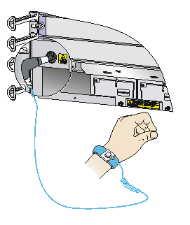
Every S10500 switch provides an ESD wrist strap. To minimize ESD damage to electronic components, wear the ESD wrist strap and make sure it is reliably grounded when installing modules.
To use an ESD wrist strap:
1. Make sure the switch is reliably grounded. For how to ground your switch, see "Grounding the switch."
2. Put on the wrist strap.
3. Tighten the wrist strap to make sure it makes good skin contact.
Make sure the resistance reading between your body and the ground is between 1 and 10 megohms.
4. As shown in Figure 3-1, insert the ESD wrist strap into the ESD socket (with an ESD sign) on the switch chassis, or attach it to the grounding screw of the chassis with an alligator clip.
Figure 3-1 Attaching an ESD wrist strap (S10506)
Installing a card
|
|
IMPORTANT: · Before installing a card in the chassis, make sure the connectors on the card are not broken or blocked to avoid damaging the backplane. · To ensure good ventilation, install a blank filler panel in an empty slot. · Before you install a card that has a protection box, remove the protection box from the card as follows: a. Loosen the captive screws that secure the card to the protection box. b. Pull the ejector levers of the card outwards. c. Pull the card out of the protection box. |
The cards for the switch include MPUs, service modules, and switching fabric modules. They are hot swappable.
· To install a card in a horizontal slot, make sure its PCB components face up.
· To install a card in a vertical slot, make sure its PCB components face left.
The installation procedure is similar for the cards. The following procedure installs a card in a horizontal slot.
To install a card:
1. Wear an ESD wrist strap, and make sure it makes good skin contact and is reliably grounded. For more information, see "Attaching an ESD wrist strap."
2. Remove the blank filler panel (if any) from the slot. Keep the blank filler panel for future use.
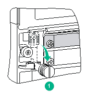
3. Fully open the two ejector levers on the card.
For a base card, rotate the ejector levers down to the horizontal position.
Figure 3-2 Rotating down the ejector levers on a base card
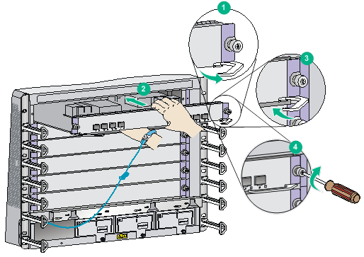
4. Hold the card by the front panel with one hand and support the card bottom with the other. Slide the card steadily into the slot along the guide rails until you cannot push the card further. Do not touch the components on the card.
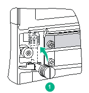
5. Fully close the ejector levers so that the card comes in close contact with the backplane.
For a base card, rotate the ejector levers inward and then upward to the vertically closed position.
Figure 3-3 Rotating up the ejector levers on a base card
6. Fasten the captive screws on the card.
7. When the switch is powered on, verify the running status of the card.
You can verify the running status of a card by referring to the card status LED (SLOT) on the MPU of the switch. If the RUN LED flashes, the card in the slot operates correctly. For more information about card status LED (SLOT), see "Appendix C LEDs."
Installing a subcard
|
|
IMPORTANT: To ensure good ventilation, install a blank filler panel in an empty subslot. |
This section describes how to install a subcard in a base card. Subcards are hot swappable.
To install a subcard:
1. Wear an ESD wrist strap, and make sure it has good skin contact and is reliably grounded. For more information, see "Attaching an ESD wrist strap."
2. Make sure a base card is installed in the switch.
3. Unpack the subcard.
4. If the target slot has a blank filler panel, remove the blank filler panel from the slot.
Keep the removed blank filler panel for future use.
5. Install the subcard in the base card:
a. Simultaneously rotate outward the two ejector levers on the subcard.
b. Gently push the subcard (with bottom up) into the slot along the guide rails until the ejector levers come in contact with the base card panel.
c. Push the subcard by its front panel until you cannot push the subcard further.
d. Rotate inward the ejector levers so that the subcard panel is flush with the base card panel.
6. Fasten the captive screws on the subcard.
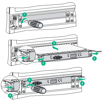
Figure 3-5 Installing a subcard
Installing a power module
|
|
CAUTION: · Provide a circuit breaker for each power module and make sure the circuit breaker is off before installation. · Do not install power modules of different models on the same switch. · When moving the power module, support the bottom of the power module, instead of holding its handle to avoid damaging the power module. · To ensure good ventilation, install a blank filler panel over an empty slot. |
The switch series uses N + 1 or N + N power redundancy and supports AC or DC power input.
The power module slots are horizontal on S10504 and S10506 switches and vertical on the S10508, S10508-V, S10510, and S10512 switches.
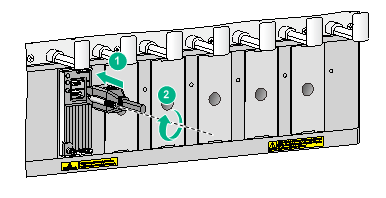
Strictly follow the order shown in Figure 3-6 to avoid security hazards.
Figure 3-6 Power module installation flow
![]()
Installing a power module
An AC power module and a DC power module are installed in the same way. This section uses an AC power module as an example.
Some power module slots do not have a blank panel. The figures in this section are for illustration only.
To install the power module:
1. Wear an ESD wrist strap and make sure it makes good skin contact and is reliably grounded. For more information, see "Attaching an ESD wrist strap."
2. Use a Phillips screwdriver to loosen the captive screws on the blank filler panel (if any) to remove the blank filler panel.
3. Unpack the power module.
4. Follow the installation graph printed on the blank filler panel of the power module to install the power module in a correct direction:
a. Grasp the handle of the module with one hand and support the module bottom with the other.
b. Push the power module along the guide rails into the slot until it has firm contact with the slot.
5. Press the handle inward until the handle seats into the slot.
6. Use a Phillips screwdriver to fasten the captive screw on the handle to attach the power module.
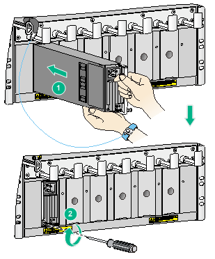
Figure 3-7 Installing a power module (AC power module in a vertical slot)
Connecting an AC power cord
|
|
CAUTION: Before connecting an AC power cord, make sure the circuit breaker at the power input end is switched off. |
To connect an AC power cord:
1. Plug the power cord into the power receptacle of the power module.
2. Use a cable tie to secure the power cord to the power cord management bracket.
¡ Figure 3-8 shows how to connect the power cord for a vertical slot switch (S10508, S10508-V, S10510, and S10512).
¡ Figure 3-9 shows how to connect the power cord for a horizontal slot switch (S10504 and S10506).
3. Plug the other end of the power cord to the AC power receptacle of the power source in the equipment room and switch on the circuit breaker.
4. Verify the power module input status LED.
If the LED is on, the power cord is correctly connected. For description of power module status LEDs, see "Appendix C LEDs."
Figure 3-8 Securing the power cord (vertical slot)
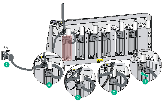
Figure 3-9 Securing the power cord (horizontal slot)
Connecting a DC power cord
|
|
WARNING! · Make sure each power cord has a separate circuit breaker. · Before you connect the power cord, make sure the circuit breaker on the power cord is switched off. · Make sure the circuit breaker at the power input end is off when you connect the DC power cord to the terminals on the power source. |
To connect the power cord:
1. Plug the power cord into the power receptacle of the power module.
2. Fasten the screw to secure the power cord.
Figure 3-10 Connecting the power cord (vertical slot)
3. (Optional) Use a cable tie to secure the power cord to the power cord management bracket. For more information, see Figure 3-8 and Figure 3-9.
4. Connect one end of the DC power cord marked with –48V to the negative terminal (–48V) on the power source; connect the DC power cord with RTN end to the positive terminal (RTN).
Setting up a PoE system (optional)
Requirements
Power over Ethernet (PoE) enables a power sourcing equipment (PSE) to supply power to powered devices (PDs) through power interfaces (PIs) over twisted pair cables. Commonly used PDs include IP telephones, APs, and web cameras.
To set up a PoE system, the following components are required:
· A switch that supports PoE—The S10506 or S10510 switch.
· An external PoE power frame—The PSE16KA0. For how to install the PSE16KA0, see "Connecting an external PoE power frame."
· PSEs—The LSUM2GV48SE0 cards.
Table3-1 LSUM2GV48SE0 specifications
|
Item |
Specification |
|
PD class |
Classes 0 to 4 |
|
Maximum power |
800 W |
|
PI quantity |
48 (RJ-45 ports) |
|
PI power |
0 W to 30 W |
|
Output voltage range |
50 VDC to 57 VDC |
|
Maximum output current |
600 mA |
Connecting an external PoE power frame
|
|
CAUTION: Make sure the power is off when you are connecting the external PoE power frame. |
To connect an external PoE power frame, perform the following tasks:
1. Connect DC power cords to the switch and external PoE power frame.
a. Connecting DC power cords to the switch.
b. Connecting DC power cords to the external PoE power frame.
2. Installing power modules on the external PoE power frame.
3. Connecting the monitoring cable.
4. Connecting the external PoE power frame to the power source.
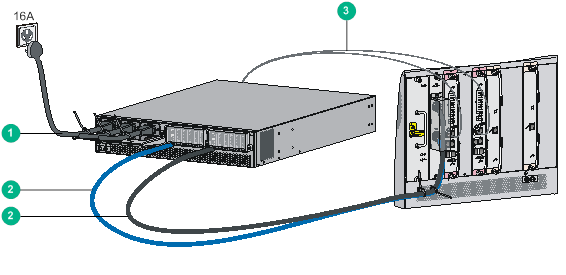
Figure 3-11 Connecting external PoE power frame (S10506)
|
(1) AC power cord |
(2) DC power cords |
|
(3) Monitoring cable |
|
|
|
NOTE: · The AC power cord and monitoring cable both are delivered with the PoE power frame (PSE16KA0). · The DC power cords are user-provided. For information about the available DC power cords, see "(Optional) PoE power system." |
Connecting DC power cords to the switch
An S10506 uses the PoE power entry module (PEM) that has one pair of power terminals. An S10510 switch uses the PoE PEM that has two pairs of power terminals.
To connect DC power cords to the switch:
1. Wear an ESD wrist strap and make sure it has good skin contact and is reliably grounded. For more information, see "Attaching an ESD wrist strap."
2. Remove the blank filler panel from the PoE PEM slot at the rear of the chassis.
Keep the blank filler panel for future use.
3. Install a PoE PEM in the slot and fasten the captive screws.
4. Connect the ring terminal marked with + of the black power cord to the power terminal marked with RTN(+) on the PoE PEM:
a. Remove the outer nut, spring washer, and flat washer from the power terminal.
b. Connect the ring terminal to the power terminal.
c. Install the flat washer, spring washer, and nut.
5. Connect the ring terminal marked with – of the blue power cord to the power terminal marked with NEG(–) on the PoE PEM. The process is the same as step 4.
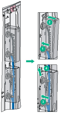
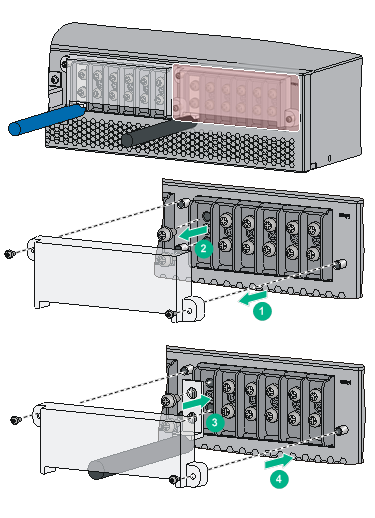
6. Install the terminal block cover over the power terminals, as shown in Figure 3-12.
To install the terminal block cover for an S10506 switch or the upper terminal block cover for an S10510 switch:
a. Insert the locking tabs on the terminal block cover into the slots in the terminal block.
b. Press the terminal block cover until the cover is securely seated.
To install the lower terminal block cover for an S10510 switch:
a. Insert the locking tabs on the terminal block cover into the slots in the terminal block.
b. Press and push the terminal block cover upward until the cover is securely seated.
Figure 3-12 Installing the upper and lower terminal block covers over the power terminals (S10510)
7. (Optional.) For an S10510 switch, repeat steps 1 to 6 to complete connection to another pair of power terminals. Make sure the upper pair of power cords are covered by both terminal block covers.
8. Use cable ties to secure the power cords to the cable hangers over the air vent section. For more information about how to use a cable tie, see Figure 3-8.
Figure 3-13 Connecting DC power cords to the switch (S10506)
Connecting DC power cords to the external PoE power frame
Each external PoE power frame has six pairs of terminals. Use one pair of terminals for an S10506 switch and use two pairs of terminals for an S10510 switch.
To connect DC power cords to the external PoE power frame:
1. Remove the terminal block cover from the external PoE power frame.
2. Connect the dual-hole lug at the other end of the black power cord to the terminal marked with RTN(+) on the external PoE power frame:
a. Use an M6 wrench to remove the nuts and washers from the terminal.
b. Connect the dual-hole lug to the terminal.
c. Install the nuts and washers.
3. Connect the dual-hole lug at the other end of the blue power cord to the terminal marked with NEG(–) on the external PoE power frame. The process is the same as step 2.
4. Install the terminal block cover.
Figure 3-14 Connecting DC power cords to the external PoE power frame
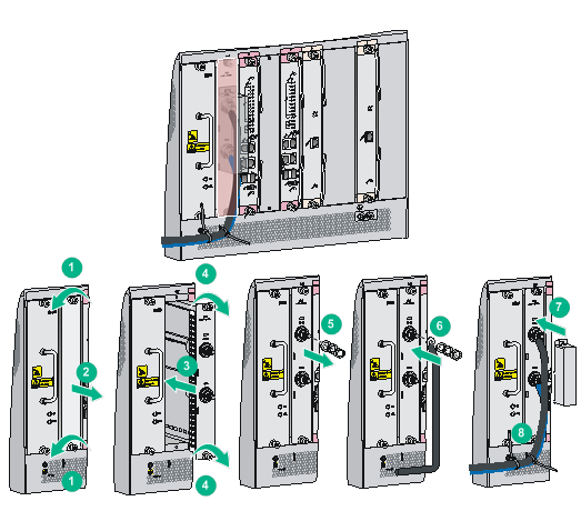
Installing power modules on the external PoE power frame
1. Wear an ESD wrist strap and make sure it has good skin contact and is reliably grounded. For more information, see "Attaching an ESD wrist strap."
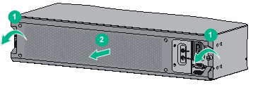
2. Loosen the screws on the front cover of the external power frame and then remove the front cover.
Figure 3-15 Removing the front cover from the external power frame
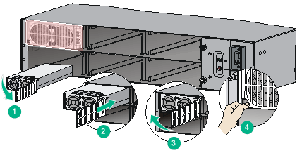
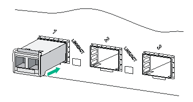
3. Pull the retaining latch at the bottom left corner of the power module to the left to open the power module cover.
4. Insert the power module slowly into the slot until it fits in completely.
5. Close the power module cover and close the retaining latch.
6. Push in the power module cover to ensure secure installation of the power module.
7. Repeat steps 3 to 5 to install other power modules.
Figure 3-16 Installing power modules
8. Reinstall the front cover of the external PoE power frame and fasten the screws.
Figure 3-17 Installing the front cover

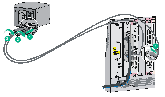
Connecting the monitoring cable
An external PoE power frame monitoring cable has two RJ-45 connectors. You can connect either of the RJ-45 connectors to the RS485 port on the MPU if the switch has only one MPU. As a best practice, use both RJ-45 connectors of the monitoring cable if the switch has two MPUs.
To connect the monitoring cable:
1. Connect the DB-9 connector of the monitoring cable to the 9-core serial port on the external PoE power frame, and fasten the screws.
2. Connect an RJ-45 connector of the monitoring cable to the RS485 port on the MPU of the switch.
Figure 3-18 Connecting the monitoring cable
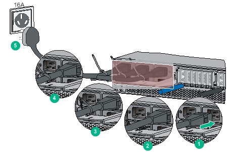
Connecting the external PoE power frame to the power source
Each receptacle on the external PoE power frame corresponds to a power module slot. To enable a power module to operate, connect the AC power cord to the correspondent receptacle.
To connect the external PoE power frame to the power source:
1. Insert the connector of the AC power cord into the receptacle of a power module.
2. Use the cable tie to secure the power cord to the power cord management bracket.
3. Repeat steps 1 and 2 for other power modules.
4. Connect connectors at the other end of the power cords to the 16A power source.
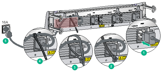
Figure 3-19 Connecting the external PoE power frame to the power source
(Optional) Installing transceiver modules and network cables
|
|
WARNING! Disconnected optical fibers or transceiver modules might emit invisible laser light. Do not stare into beams or view directly with optical instruments when the switch is operating. |
Installing transceiver modules
|
|
CAUTION: To avoid transceiver module or port damage, read this guide carefully before installing a transceiver module. |
|
CAUTION: · Be careful not to touch the golden plating on a transceiver module during the installation process. · Before installing a transceiver module, remove the optical fibers, if any, from it. · Make sure the transceiver module is aligned correctly with the target port before pushing it into the port. · Do not remove the dust plugs from a transceiver module until you are ready to connect optical fibers to it. |
Installing an XFP/SFP+/SFP/SFP28/QSFP+/QSFP28 module
Two types of QSFP+ transceiver modules are available. One type uses a metal pull latch and the other type uses a plastic pull latch. The installation procedure is the same for the two types of QSFP+ transceiver modules.
The installation procedure is similar for the XFP, SFP+, SFP, SFP28, QSFP+, and QSFP28 transceiver modules. The following procedure installs an SFP+ transceiver module.
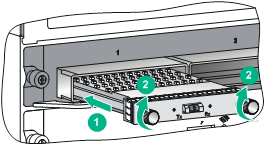
To install an SFP+ transceiver module:
1. Wear an ESD wrist strap and make sure it makes good skin contact and is reliably grounded. For more information, see "Attaching an ESD wrist strap."
2. Remove the dust plug from the target fiber port.
3. Unpack the SFP+ module. It comes with the bail latch catching the knob on the top of the transceiver module.
4. Grasp the transceiver module between your thumb and index finger. Align it with the fiber port and push it gently into the port until it snaps into place.
Transceiver modules and fiber ports have disorientation rejection designs. If you cannot insert a transceiver module easily into a port, the orientation might be wrong. Remove and reorient the transceiver module.
In case of limited space, you can gently push against the front face of the transceiver module instead of the two sides.
5. Connect optical fibers to the transceiver module. For the connection procedure, see "Connecting your switch to the network through optical fibers."
Figure 3-20 Installing an SFP+ module
Installing a CFP module
1. Wear an ESD wrist strap and make sure it makes good skin contact and is reliably grounded. For more information, see "Attaching an ESD wrist strap."
2. Remove the dust plug from the target fiber port.
3. Unpack the CFP module.
4. Correctly orient the transceiver module and align it with the fiber port. Push it gently into the port until you feel it snaps into place. See Figure 3-21.
Transceiver modules and fiber ports have disorientation rejection designs. If you cannot insert a transceiver module easily into a port, the orientation might be wrong. Remove and reorient the transceiver module.
In case of limited space, you can gently push against the front face of the transceiver module instead of the two sides.
5. Fasten the captive screws on the transceiver module to secure the module in place.
6. Connect optical fibers to the transceiver module. For the connection procedure, see "Connecting your switch to the network through optical fibers."
Figure 3-21 Installing a CFP module
Connecting network cables
|
|
CAUTION: When you connect a network cable, follow these restrictions and guidelines: · Make sure the two modular ends of a network cable are compatible with the ports into which they will be inserted. · Do not touch the golden plating on the two modular ends of a network cable. · To avoid network cable damage and signal loss, do not strain or tangle a network cable. · Before inserting a modular end of a network cable into a port, make sure the module aligns with the port correctly. · The bend radius of a DAC cable and AOC cable must be a minimum of 15 and 20 times the cable diameter, respectively. |
To connect ports over a short distance, use network cables as follows:
· SFP+ DAC cable—Connects two SFP+ ports over a short distance.
· QSFP+ DAC cable or QSFP+ AOC cable—Connects two QSFP+ ports over a short distance.
· QSFP+ to SFP+ DAC cable—Connects one QSFP+ port to four SFP+ ports over a short distance.
The network cables are hot swappable. The connection procedure is similar for these cables. The following procedure connects an SFP+ DAC cable.
To connect an SFP+ DAC cable:
1. Wear an ESD wrist strap and make sure it makes good skin contact and is reliably grounded. For more information, see "Attaching an ESD wrist strap."
2. Remove the dust plug from the target fiber port.
3. Unpack the cable.
4. As shown in Figure 3-22, align the module end of the cable with the fiber port and push it gently into the port until you feel it snaps into place.
Transceiver modules and fiber ports have disorientation rejection structures. If you cannot insert a transceiver module easily into a port, remove and reorient the transceiver module.
Figure 3-22 Connecting an SFP+ DAC cable
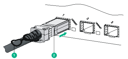
|
(1) Pull latch |
(2) Connector |