- Table of Contents
-
- H3C S10500 Switch Series Installation Guide-6W208
- 00-Preface
- 01-Chapter 1 Preparing for Installation
- 02-Chapter 2 Installing the Switch
- 03-Chapter 3 Installing FRUs
- 04-Chapter 4 Connecting Your Switch to the Network
- 05-Chapter 5 Replacement Procedures
- 06-Chapter 6 Troubleshooting
- 07-Appendix A Chassis Views and Technical Specifications
- 08-Appendix B FRUs and Compatibility Matrixes
- 09-Appendix C LEDs
- 10-Appendix D Cables
- 11-Appendix E Engineering Labels
- 12-Appendix F Cable Management
- 13-Appendix G Repackaging the Switch
- Related Documents
-
| Title | Size | Download |
|---|---|---|
| 05-Chapter 5 Replacement Procedures | 10.25 MB |
Contents
Replacing the air filter from an S10508-V switch
Replacing an air filter from S10500 switch models except the S10508-V
Replacing PoE system components
Replacing a PoE power module for the external PoE power frame
Replacing a power monitoring module for the external PoE power frame
Replacing the air filter for the external PoE power frame
Replacing a transceiver module or network cable
Replacing a transceiver module
5 Replacement procedures
|
|
CAUTION: · Ensure electrical safety when you hot swap an FRU. · To avoid bodily injury and device damage, strictly follow the replacement procedure in this section when you replace a component. |
The switch uses a modular, hot-swappable architecture, and supports field replaceable units (FRUs). You can replace any FRU when the switch is operating.
Replacing mounting brackets
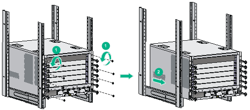
1. Remove the screws that secure the chassis to the rack.
2. Cooperate with one or more people to slowly pull out the chassis along the guide rails until the space is enough for replacing the mounting brackets.
Figure 5-1 Pulling out the chassis (S10506)
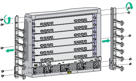
3. Removing the mounting brackets, as shown in Figure 5-2.
Figure 5-2 Removing mounting brackets (S10506)
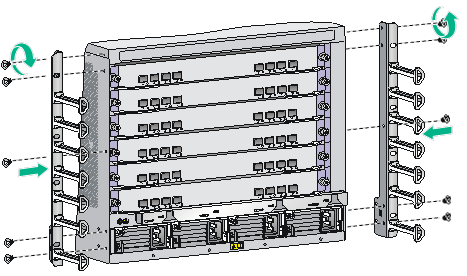
4. Install the new mounting brackets.
Figure 5-3 Installing mounting brackets (S10506)
5. Cooperate with one or more people to push the chassis back to the rack, and fasten the screws to secure the chassis to the rack. For more information, see "Mounting the switch in the rack."
Replacing a power module
Follow these guidelines when you replace a power module:
· Strictly follow the procedures shown in Figure 5-4 and Figure 5-5 to replace a power module to avoid device damage or bodily injury.
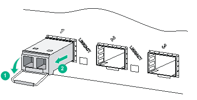
Figure 5-4 Power module removal procedure
![]()
Figure 5-5 Power module installation procedure
![]()
· Power modules on the switch must be the same model. When the new power modules and the existing power modules are not the same model, power off the switch and remove all existing power modules before installing new power modules.
· Provide a circuit breaker for each power module. Before replacing a power module, turn off its circuit breaker.
· The power module might be of high temperature. Remove it with caution.
· To install the removed power module in the chassis again, install it after the status LED on it is off.
· After removing the power module from a slot, install a blank filler panel in the slot if you do not install a new power module.
To replace a power module:
1. Prepare an antistatic mat to place the removed power module.
2. Turn off the circuit breaker.
3. Wear an ESD wrist strap and make sure it makes good skin contact and is reliably grounded. For more information, see "Attaching an ESD wrist strap."
4. Remove the power cord plug from the power module.
¡ AC power cord: Remove the cable ties from the power cord, and remove the power cord plug from the power module.
¡ DC power cord: Remove the cable ties from the power cord, loosen the fastening screw on the power cord plug, and remove the plug from the power module.
5. Use a Phillips screwdriver to loosen the captive screw on the power module, and then grasp the captive screw between your thumb and index finger to carefully pull out the handle on the power module.
6. Holding the power module handle with one hand and supporting the bottom of the power module with the other, gently pull the power module out.
7. Put the removed power module on the antistatic mat.
8. Install a new power module. For the installation procedures, see "Installing a power module."
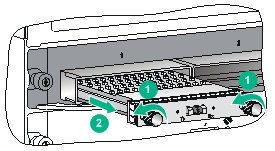
Figure 5-6 Removing a vertically oriented AC power module
Replacing a card
|
|
CAUTION: · To remove the only MPU on the switch, first power off the switch. · Before you remove an MPU or service module, remove the cables from it. · Before you install the removed card again, make sure the status LED on it is off. · Install a blank filler panel in the slot where you are not to install a card. · To remove a switching fabric module or standby MPU, first press the OFFLINE button (if any) on it. · Do not press the OFFLINE button on the active MPU. |
The cards on the S10500 switches can be installed in horizontal or vertical slots, and the replacement procedures are the same. The following takes a card installed in a horizontal slot as an example.
To replace a card:
1. Prepare an antistatic mat to place the removed card.
2. Wear an ESD wrist strap and make sure it makes good skin contact and is reliably grounded. For more information, see "Attaching an ESD wrist strap."
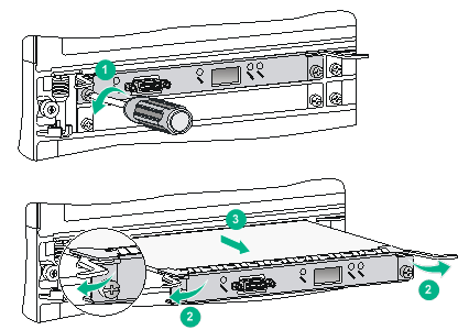
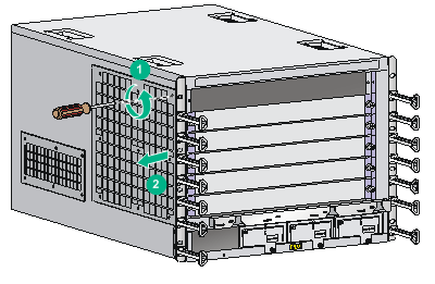
3. Use a Phillips screwdriver to remove the captive screw on the card, as shown by callout 1 in Figure 5-7.
4. Press the ejector buttons on the ejector levers to release the ejector levers. (This step is applicable only to a switching fabric module with ejector buttons on the ejector levers.)
5. Simultaneously rotate outward the ejector levers to separate the card from the backplane, as shown by callout 2 in Figure 5-7.
For a base card, rotate the ejector levers downward to the horizontal position as shown in Figure 5-8.
6. Use one hand to slowly move the card outwards. Supporting the bottom of the card with the other hand, pull the card out of the slot along slide rails, as shown by callout 3 in Figure 5-7.
7. Put the removed card on the antistatic mat.
8. Install a new card. For the installation procedures, see "Installing a card."
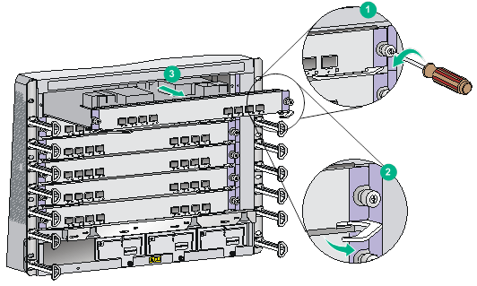
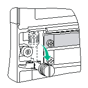
Figure 5-8 Rotating the ejector levers of the base card downward
Replacing a subcard
|
|
WARNING! · Before you install the removed subcard again, make sure the status LED on it is off. · Install a blank filler panel in the slot where you are not to install a subcard. |
The switch supports hot swapping of subcards.
To replace a subcard:
1. Put on an ESD wrist strap, and make sure the wrist strap makes good skin contact and is reliably grounded. For more information, see "Attaching an ESD wrist strap."
2. Use a Phillips screwdriver to loosen the mounting screws on the subcard.
3. Rotate the ejector levers outward to unseat the subcard from the base card.
4. Slowly pull out the subcard along the guide rails, as shown in Figure 5-9.
5. Put the removed subcard on an antistatic mat or into the original package.
6. Install a new subcard. For more information about how to install a subcard, see "Installing a subcard."
Replacing a fan tray
|
|
CAUTION: · To avoid bodily injury, do not touch the rotating fans when replacing the fan tray. · To ensure good ventilation, install a new fan tray within two minutes after removing the old one. |
When a fan tray fails, replace the fan tray to ensure correct operation of the switch.
The fan tray removal and installation procedures for all S10500 switches are the same, even though the fan tray slot is vertically oriented for the S10504, S10506, S10508, S10510, and S10512 switches and horizontally oriented for the S10508-V switch. This section takes removing and installing a vertically oriented fan tray on an S10506 as an example.
To remove a fan tray:
1. Prepare an antistatic mat to place the fan tray to be removed.
2. Put on an ESD wrist strap and make sure the wrist strap makes good skin contact and is reliably grounded. For more information, see "Attaching an ESD wrist strap."
3. Loosen the captive screws on the fan tray.
4. Hold the handle of the fan tray with one hand to gently pull the fan tray part way out of the chassis. After the fans stop rotating, support the bottom of the fan tray with the other hand, and take out the fan tray from the chassis.
5. Put the removed fan tray on the antistatic mat.
6. Unpack the fan tray.
7. Holding the handle of the fan tray with one hand and supporting the bottom with the other, gently slide the fan tray along the guide rails into the slot until it is firmly seated in the slot.
8. Fasten the captive screws on the fan tray.
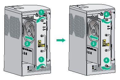
Figure 5-10 Replacing a fan tray
|
(A) Fan tray to be removed |
(B) Fan tray to be installed |
Replacing an air filter
|
|
CAUTION: Clean air filters every three months to guarantee adequate ventilation and avoid over-temperature. |
The air filter of the S10508-V is different than other models.
· The S10508-V has one air filter installed at the lower part of the chassis front. The air filter uses captive screws.
· The S10504, S10506, S10508, and S10510 each have two air filters, and the S10512 has three air filters installed on the left of the chassis. These air filters use countersunk screws.
Replacing the air filter from an S10508-V switch
1. Loosen the captive screws on the air filter.
2. Remove the air filter from the chassis.
3. Clean the air filter and reinstall it on the switch.
For the installation procedure, see "Installing an air filter for an S10508-V switch."
Figure 5-11 Removing an air filter from an S10508-V switch
Replacing an air filter from S10500 switch models except the S10508-V
The air filter replacement procedure is similar for S10500 switch models except the S10508-V. This section replaces an air filter on an S10506 switch.
To replace an air filter:
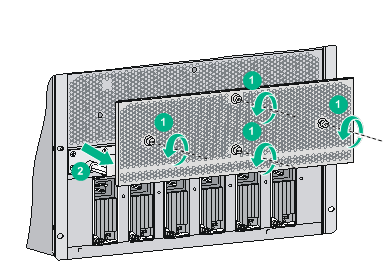
1. Remove the countersunk screws on the air filter.
Keep the removed screws secure for future use.
2. Remove the air filter from the chassis.
3. Clean the air filter and reinstall it on the switch. For the installation procedure, see "Installing air filters for S10500 switch models except the S10508-V."
Figure 5-12 Removing an air filter
Replacing PoE system components
|
|
WARNING! · Make sure the power is off when you are replacing a PoE system component. · After you switch off the power of the external PoE power frame, do not switch on the power again within 30 seconds. |
Replacing a PoE PEM
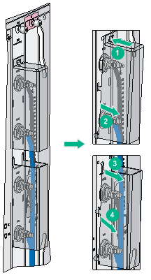
1. Remove the cable tie from the DC power cords.
2. Remove the terminal block cover over the power terminals, as shown in Figure 5-13.
To remove the terminal block cover for an S10506 switch or the upper terminal block cover for an S10510 switch:
a. Press the top locking tab on the terminal block cover.
b. Gently lift the terminal block cover to loosen the locking tabs on the cover from the slots in the terminal block.
To remove the lower terminal block cover for an S10510 switch:
a. Gently lift the terminal block cover to loosen the upper locking tabs on the cover from the slots in the terminal block.
b. Push the terminal block cover downward to loosen the other locking tabs from the slots in the terminal block.
Figure 5-13 Removing the upper and lower terminal block covers over the power terminals
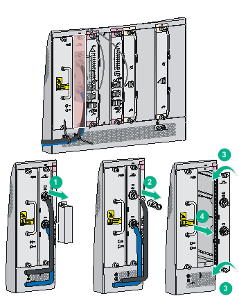
3. Remove the outer nuts, spring washers, and flat washers from the power terminals.
4. Remove the ring terminals of the power cords from the power terminals.
5. Loosen the captive screws on the PoE PEM and slightly pull the module out.
6. Install the new PoE PEM and connect DC power cords to power terminals on it. For more information, see "(Optional) Setting up a PoE system."
7. Install the terminal block cover, and secure the power cords with cable ties. For information about installing the terminal block cover, see "(Optional) Setting up a PoE system."
Figure 5-14 Removing the PoE PEM (S10506)
Replacing a PoE power module for the external PoE power frame
|
|
WARNING! Before you install the removed power module again, make sure the status LED on the power module is off. |
|
|
CAUTION: Before replacing a PoE power module, make sure other PoE power modules are available in the external PoE power frame for PoE power supply. |
To replace a PoE power module for the external PoE power frame:
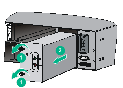
1. Remove the DB-9 connector from the external PoE power frame.
Figure 5-15 Removing the DB-9 connector
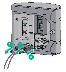
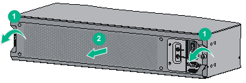
2. Loosen the screws on the front cover of the external PoE power frame and remove the front cover.
Figure 5-16 Removing the front cover
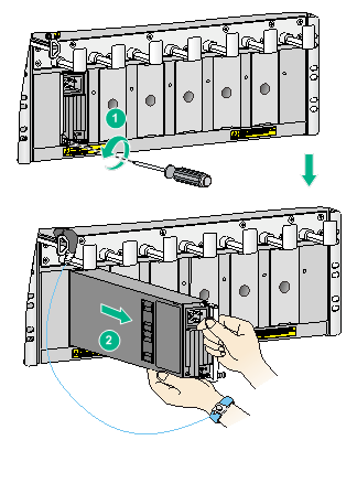
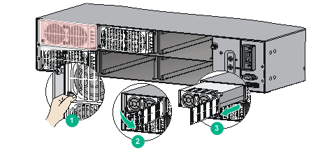
3. Pull the retaining latch at the bottom left corner of the power module to the left to open the power module cover.
4. Hold the bottom of the power module, gently pull out the module by its front panel.
Figure 5-17 Removing the power module
5. Install the new power module. For more information, see "Connecting an external PoE power frame."
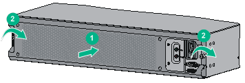
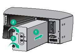
6. Reinstall the front cover for the external PoE power frame and fasten the captive screws.
Figure 5-18 Installing the front cover
7. Connect the DB-9 connector to the 9-core serial port on the external PoE power frame, and fasten the captive screws.
Figure 5-19 Connecting the DB-9 connector

Replacing a power monitoring module for the external PoE power frame
1. Remove the DB-9 connector from the external PoE power frame, as shown in Figure 5-15.
2. Remove the front cover from the external PoE power frame, as shown in Figure 5-16.
3. Loosen the captive screws on the power monitoring module, and slightly pull the module out.
Figure 5-20 Removing the power monitoring module
4. Put the removed power monitoring module on an antistatic bag or into the original package.
5. Unpack the new power monitoring module.
6. Slightly push the new power monitoring module into the slot and fasten the captive screws.
Figure 5-21 Installing the power monitoring module
7. Reinstall the front cover for the external power frame, as shown in Figure 5-18.
8. Connect the DB-9 connector to the 9-core serial port on the external PoE power frame, and secure the captive screws, as shown in Figure 5-19.
Replacing the air filter for the external PoE power frame
1. Remove the DB-9 connector from the external PoE power frame, as shown in Figure 5-15.
2. Remove the front cover from the external PoE power frame, as shown in Figure 5-16.
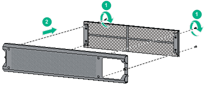
3. Use a screwdriver to loosen screws on the air filter.
4. Remove the air filter from the front cover.
Figure 5-22 Removing the air filter
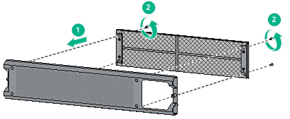
5. Secure the new air filter to the front cover and fasten the screws.
Figure 5-23 Installing the new air filter
6. Reinstall the front cover for the external PoE power frame, as shown in Figure 5-18.
7. Connect the DB-9 connector to the 9-core serial port on the external PoE power frame, and secure the captive screws, as shown in Figure 5-19.
Replacing a transceiver module or network cable
|
|
WARNING! Disconnected optical fibers or transceiver modules might emit invisible laser light. Do not stare into beams or view directly with optical instruments when the switch is operating. |
Replacing a transceiver module
|
|
CAUTION: · Do not touch the golden plating on a transceiver module during the replacement process. · After removing a transceiver module, you must wait a minimum of 5 seconds before installing a new transceiver module. · Make sure the new transceiver module is the same model as the peer transceiver module at the other end of the optical fiber. |
Replacing an XFP/SFP+/SFP/SFP28/QSFP+/QSFP28 module
The replacement procedure is similar for XFP modules, SFP+ modules, SFP modules, SFP28 modules, QSFP+ modules, and QSFP28 modules. The following procedure replaces an SFP+ module.
To replace an SFP+ module:
1. Wear an ESD wrist strap and make sure it makes good skin contact and is reliably grounded.
For more information, see "Attaching an ESD wrist strap."
2. Remove the optical fibers from the module.
There is a latching mechanism between a fiber connector and transceiver module bore to prevent connector disengagement. Release the latching before removing the optical fiber. To avoid damages, do not use excessive force.
3. Pivot the bail latch down to the horizontal position.
For a QSFP+ or QSFP28 module that uses a plastic pull latch, skip this step.
4. Hold the bail latch to pull the module out of the slot. Make sure you apply force in the direction parallel to the ground. To avoid damaging the bail latch, do not use excessive force.
If you apply force at an angle when pulling the module out, you can hardly pull the module out and the module or fiber port might be damaged.
5. Insert dust plugs into the removed module, and put the module into its packaging bag.
6. Install a new module. For the installation procedure, see "Installing transceiver modules."
Figure 5-24 Removing an SFP+ module
Replacing a CFP module
1. Wear an ESD wrist strap and make sure it makes good skin contact and is reliably grounded.
For more information, see "Attaching an ESD wrist strap."
2. Remove the optical fibers from the module.
There is a latching mechanism between a fiber connector and transceiver module port to prevent connector disengagement. Release the latching before removing the optical fiber. To avoid damages, do not use excessive force.
3. Loosen the captive screws on the transceiver module.
4. Carefully pull the module out of the slot. Make sure you apply force in the direction parallel to the ground.
If you apply force at an angle, you can hardly pull the module out and the module or fiber port might be damaged.
5. Insert the plugs into the removed module, and put the module into its packaging bag.
6. Install a new module. For the installation procedure, see "Installing transceiver modules."
Figure 5-25 Removing a CFP module
Replacing a network cable
|
|
CAUTION: · Do not touch the golden plating on the two modular ends of a network cable during the replacement process. · Make sure the two modular ends of the new network cable are compatible with the ports into which they will be inserted. · To avoid network cable damage and signal loss, do not strain or tangle a network cable. · Before inserting a modular end of a network cable into a port, make sure the module aligns with the port correctly. · If a network cable cannot be removed or installed, verify that the removal or installation procedure is correct. Do not use excessive force. |
The replacement procedure is the same for network cables. The following procedure replaces an SFP+ DAC cable.
To replace an SFP+ DAC cable:
1. Wear an ESD wrist strap and make sure it makes good skin contact and is reliably grounded. For more information, see "Attaching an ESD wrist strap."
2. Push the modular end of the cable gently inward to release the latching mechanism. Then use the pull latch on the cable to pull the modular end out of the slot. Make sure you apply force in the direction parallel to the ground. To avoid damaging the pull latch, do not use excessive force.
If you apply force at an angle when pulling the module out, you can hardly pull the network cable out and the network cable or fiber port might be damaged.
Figure 5-26 Removing an SFP+ DAC cable

3. Install a new cable. For the installation procedures, see "Connecting network cables."