- Table of Contents
-
- H3C S6850&S9850&S9820-64H Config Examples-Release 655x-6W100
- 01-Login Management Configuration Examples
- 02-RBAC Configuration Examples
- 03-Software Upgrade Examples
- 04-ISSU Configuration Examples
- 05-Software Patching Examples
- 06-Ethernet Link Aggregation Configuration Examples
- 07-Port Isolation Configuration Examples
- 08-Spanning Tree Configuration Examples
- 09-VLAN Configuration Examples
- 10-VLAN Tagging Configuration Examples
- 11-DHCP Snooping Configuration Examples
- 12-Cross-Subnet Dynamic IP Address Allocation Configuration Examples
- 13-IPv6 over IPv4 Manual Tunneling with OSPFv3 Configuration Examples
- 14-ISATAP Tunnel and 6to4 Tunnel Configuration Examples
- 15-GRE Tunnel Configuration Examples
- 16-GRE with OSPF Configuration Examples
- 17-OSPF Configuration Examples
- 18-IS-IS Configuration Examples
- 19-BGP Configuration Examples
- 20-Policy-Based Routing Configuration Examples
- 21-OSPFv3 Configuration Examples
- 22-IPv6 IS-IS Configuration Examples
- 23-Routing Policy Configuration Examples
- 24-IGMP Snooping Configuration Examples
- 25-IGMP Configuration Examples
- 26-BIDIR-PIM Configuration Examples
- 27-MLD Snooping Configuration Examples
- 28-IPv6 Multicast VLAN Configuration Examples
- 29-Basic MPLS Configuration Examples
- 30-MPLS L3VPN Configuration Examples
- 31-ACL Configuration Examples
- 32-Control Plane-Based QoS Policy Configuration Examples
- 33-Traffic Policing Configuration Examples
- 34-GTS and Rate Limiting Configuration Examples
- 35-Priority Mapping and Queue Scheduling Configuration Examples
- 36-Traffic Filtering Configuration Examples
- 37-AAA Configuration Examples
- 38-Port Security Configuration Examples
- 39-Portal Configuration Examples
- 40-SSH Configuration Examples
- 41-IP Source Guard Configuration Examples
- 42-Ethernet OAM Configuration Examples
- 43-CFD Configuration Examples
- 44-DLDP Configuration Examples
- 45-VRRP Configuration Examples
- 46-BFD Configuration Examples
- 47-NTP Configuration Examples
- 48-SNMP Configuration Examples
- 49-NQA Configuration Examples
- 50-Mirroring Configuration Examples
- 51-sFlow Configuration Examples
- 52-FCoE Configuration Examples
- 53-OpenFlow Configuration Examples
- 54-MAC Address Table Configuration Examples
- 55-Static Multicast MAC Address Entry Configuration Examples
- 56-IP Unnumbered Configuration Examples
- 57-MVRP Configuration Examples
- 58-MCE Configuration Examples
- 59-Congestion Avoidance and Queue Scheduling Configuration Examples
- 60-Attack Protection Configuration Examples
- 61-Smart Link Configuration Examples
- 62-RRPP Configuration Examples
- 63-BGP Route Selection Configuration Examples
- 64-IS-IS Route Summarization Configuration Examples
- 65-IRF Configuration Examples
- 66-MPLS OAM Configuration Examples
- 67-MPLS TE Configuration Examples
- 68-VXLAN Configuration Examples
- 69-NetStream Configuration Examples
- 70-DRNI Configuration Examples
- 71-DRNI and EVPN Configuration Examples
- 72-EVPN-DCI over an MPLS L3VPN Network Configuration Examples
- 73-VCF Fabric Configuration Examples
- 74-PTP Configuration Examples
- 75-S-MLAG Configuration Examples
- 76-Puppet Configuration Examples
- Related Documents
-
| Title | Size | Download |
|---|---|---|
| 26-BIDIR-PIM Configuration Examples | 127.72 KB |
|
|
|
H3C S6850 & S9850 & S9820-64H |
|
BIDIR-PIM Configuration Examples |
|
|
Copyright © 2020 New H3C Technologies Co., Ltd. All rights reserved.
No part of this manual may be reproduced or transmitted in any form or by any means without prior written consent of New H3C Technologies Co., Ltd.
Except for the trademarks of New H3C Technologies Co., Ltd., any trademarks that may be mentioned in this document are the property of their respective owners.
The information in this document is subject to change without notice.
Introduction
This document introduces BIDIR-PIM configuration examples.
Prerequisites
This document is not restricted to specific software or hardware versions.
The configuration examples in this document were created and verified in a lab environment, and all the devices were started with the factory default configuration. When you are working on a live network, make sure you understand the potential impact of every command on your network.
This document assumes that you have basic knowledge of BIDIR-PIM.
Example: Configuring BIDIR-PIM
Network configuration
As shown in Figure 1:
· Switch A, Switch B, and Switch C run OSPF.
· Source 1 and Source 2 send multicast data to multicast group 225.1.1.1.
· Host A and Host B are member hosts of multicast group 225.1.1.1.
Configure BIDIR-PIM on the switches to implement multicast forwarding.
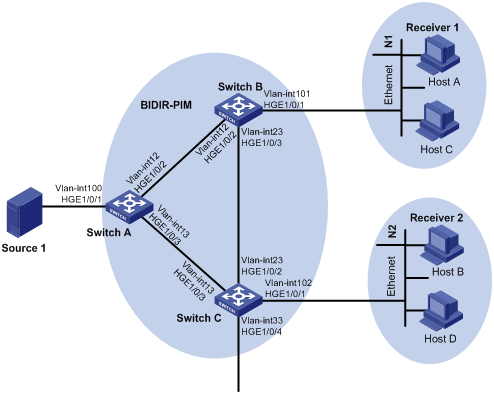
Table 1 Interface and IP address assignment
|
Device |
Interface |
IP address |
Device |
Interface |
IP address |
|
Switch A |
Vlan-int100 |
10.10.1.1/24 |
Switch C |
Vlan-int102 |
10.102.1.1/24 |
|
Switch A |
Vlan-int12 |
10.12.1.1/24 |
Switch C |
Vlan-int13 |
10.13.1.3/24 |
|
Switch A |
Vlan-int13 |
10.13.1.1/24 |
Switch C |
Vlan-int23 |
10.23.1.3/24 |
|
Switch B |
Vlan-int101 |
10.101.1.1/24 |
Switch C |
Vlan-int33 |
|
|
Switch B |
Vlan-int12 |
10.12.1.2/24 |
Source 1 |
— |
10.10.1.2/24 |
|
Switch B |
Vlan-int23 |
10.23.1.2/24 |
Source 2 |
— |
10.33.1.4/24 |
Analysis
To meet the network requirements, perform the following tasks:
· To establish the bidirectional RPT, configure VLAN-interface 12 on Switch A as a C-RP.
· To use the BSR mechanism to dynamically elect the RP, configure VLAN-interface 12 on Switch A as a C-BSR.
· To avoid multicast forwarding interruption when the RP fails, specify the unused IP address 10.13.1.4/24 as the static RP. In this way, the link on the subnet 10.13.1.0/24 becomes the RPL. Switch A and Switch C on the link function as the RPs.
Applicable hardware and software versions
The following matrix shows the hardware and software versions to which this configuration example is applicable:
|
Hardware |
Software version |
|
S6850 switch series S9850 switch series |
Release 6555P01 |
|
S9820-64H switch |
Release 6555P01 |
Restrictions and guidelines
When you configure BIDIR-PIM, follow these restrictions and guidelines:
· Enable the same PIM mode on the interfaces that belong to the same VPN instance on each switch.
· Configure the same static RP on all the switches in the BIDIR-PIM domain.
· Enable PIM-SM for all interfaces on the switches in the BIDIR-PIM domain.
· Enable IGMP for the interfaces that connect to the stub networks on all the switches in the BIDIR-PIM domain.
Procedures
Configure Switch A
1. Enable IP multicast routing.
<SwitchA> system-view
System View: return to User View with Ctrl+Z.
[SwitchA] multicast routing
[SwitchA-mrib] quit
2. Configure each interface and enable PIM-SM.
# Create VLAN 100, and assign HundredGigE 1/0/1 to this VLAN.
[SwitchA] vlan 100
[SwitchA-vlan100] port hundredgige 1/0/1
[SwitchA-vlan100] quit
# Assign an IP address to VLAN-interface 100, and enable PIM-SM on the interface.
[SwitchA] interface vlan-interface 100
[SwitchA-Vlan-interface100] ip address 10.10.1.1 24
[SwitchA-Vlan-interface100] pim sm
[SwitchA-Vlan-interface100] quit
# Create VLAN 12, and assign HundredGigE 1/0/2 to the VLAN.
[SwitchA] vlan 12
[SwitchA-vlan12] port hundredgige 1/0/2
[SwitchA-vlan12] quit
# Assign an IP address to VLAN-interface 12, enable PIM-SM on the interface.
[SwitchA-vlan12] interface vlan-interface 12
[SwitchA-Vlan-interface12] ip address 10.12.1.1 24
[SwitchA-Vlan-interface12] pim sm
[SwitchA-Vlan-interface12] quit
# Create VLAN 13, and assign HundredGigE 1/0/3 to the VLAN.
[SwitchA] vlan 13
[SwitchA-vlan13] port hundredgige 1/0/3
[SwitchA-vlan13] quit
# Assign an IP address to VLAN-interface 13, enable PIM-SM on the interface.
[SwitchA] interface vlan-interface 13
[SwitchA-Vlan-interface13] ip address 10.13.1.1 24
[SwitchA-Vlan-interface13] pim sm
[SwitchA-Vlan-interface13] quit
3. Configure a C-RP, a C-BSR, and the static RP.
# Configure VLAN-interface 12 as a C-BSR and a C-RP.
[SwitchA] pim
[SwitchA-pim] c-bsr 10.12.1.1
[SwitchA-pim] c-rp 10.12.1.1 bidir
# Specify the unused IP address 10.13.1.4 as a static RP.
[SwitchA-pim] static-rp 10.13.1.4 bidir
4. Enable BIDIR-PIM.
[SwitchA-pim] bidir-pim enable
[SwitchA-pim] quit
5. Configure OSPF.
[SwitchA] ospf 1
[SwitchA-ospf-1] import-route direct
[SwitchA-ospf-1] area 0
[SwitchA-ospf-1-area-0.0.0.0] network 10.0.0.0 0.255.255.255
[SwitchA-ospf-1-area-0.0.0.0] quit
[SwitchA-ospf-1] quit
Configure Switch B
1. Enable IP multicast routing.
<SwitchB> system-view
System View: return to User View with Ctrl+Z.
[SwitchB] multicast routing
[SwitchB-mrib] quit
2. Configure each interface and enable PIM-SM.
# Create VLAN 12, and assign HundredGigE 1/0/2 to this VLAN.
[SwitchB] vlan 12
[SwitchB-vlan12] port hundredgige 1/0/2
[SwitchB-vlan12] quit
# Assign an IP address to VLAN-interface 12, enable PIM-SM on the interface.
[SwitchB] interface vlan-interface 12
[SwitchB-Vlan-interface12] ip address 10.12.1.2 24
[SwitchB-Vlan-interface12] pim sm
[SwitchB-Vlan-interface12] quit
# Create VLAN 23, and assign HundredGigE 1/0/3 to this VLAN.
[SwitchB] vlan 23
[SwitchB-vlan23] port hundredgige 1/0/3
[SwitchB-vlan23] quit
# Assign an IP address to VLAN-interface 23, enable PIM-SM on the interface.
[SwitchB] interface vlan-interface 23
[SwitchB-Vlan-interface23] ip address 10.23.1.2 24
[SwitchB-Vlan-interface23] pim sm
[SwitchB-Vlan-interface23] quit
# Create VLAN 101, and assign HundredGigE 1/0/1 to this VLAN.
[SwitchB] vlan 101
[SwitchB-vlan101] port hundredgige 1/0/1
[SwitchB-vlan101] quit
# Assign an IP address to VLAN-interface 101, enable PIM-SM and IGMP on the interface.
[SwitchB] interface vlan-interface 101
[SwitchB-Vlan-interface101] ip address 10.101.1.1 24
[SwitchB-Vlan-interface101] igmp enable
[SwitchB-Vlan-interface101] quit
3. Specify the unused IP address 10.13.1.4 as a static RP.
[SwitchB] pim
[SwitchB-pim] static-rp 10.13.1.4 bidir
4. Enable BIDIR-PIM.
[SwitchB-pim] bidir-pim enable
[SwitchB-pim] quit
5. Configure OSPF.
[SwitchB] ospf 1
[SwitchB-ospf-1] import-route direct
[SwitchB-ospf-1] area 0
[SwitchB-ospf-1-area-0.0.0.0] network 10.0.0.0 0.255.255.255
[SwitchB-ospf-1-area-0.0.0.0] quit
[SwitchB-ospf-1] quit
Configure Switch C
1. Enable IP multicast routing.
<SwitchC> system-view
System View: return to User View with Ctrl+Z.
[SwitchC] multicast routing
[SwitchC-mrib] quit
2. Configure each interface and enable PIM-SM.
# Create VLAN 33, and assign HundredGigE 1/0/4 to this VLAN.
[SwitchC] vlan 33
[SwitchC-vlan33] port hundredgige 1/0/4
[SwitchC-vlan33] quit
# Assign an IP address to VLAN-interface 33, enable PIM-SM on the interface.
[SwitchC] interface vlan-interface 33
[SwitchC-Vlan-interface33] ip address 10.33.1.3 24
[SwitchC-Vlan-interface33] pim sm
[SwitchC-Vlan-interface33] quit
# Create VLAN 13, and assign HundredGigE 1/0/3 to this VLAN.
[SwitchC] vlan 13
[SwitchC-vlan13] port hundredgige 1/0/3
[SwitchC-vlan13] quit
# Assign an IP address to VLAN-interface 13, enable PIM-SM on the interface.
[SwitchC] interface vlan-interface 13
[SwitchC-Vlan-interface13] ip address 10.13.1.3 24
[SwitchC-Vlan-interface13] pim sm
[SwitchC-Vlan-interface13] quit
# Create VLAN 23, and assign HundredGigE 1/0/2 to this VLAN.
[SwitchC] vlan 23
[SwitchC-vlan23] port hundredgige 1/0/2
[SwitchC-vlan23] quit
# Assign an IP address to VLAN-interface 23, enable PIM-SM on the interface.
[SwitchC] interface vlan-interface 23
[SwitchC-Vlan-interface23] ip address 10.23.1.3 24
[SwitchC-Vlan-interface23] pim sm
[SwitchC-Vlan-interface23] quit
# Create VLAN 102, and assign HundredGigE 1/0/1 to this VLAN.
[SwitchC] vlan 102
[SwitchC-vlan102] port hundredgige 1/0/1
[SwitchC-vlan102] quit
# Assign an IP address to VLAN-interface 102, enable PIM-SM and IGMP on the interface.
[SwitchC] interface vlan-interface 102
[SwitchC-Vlan-interface102] ip address 10.102.1.1 24
[SwitchC-Vlan-interface102] igmp enable
[SwitchC-Vlan-interface102] quit
3. Specify the unused IP address 10.13.1.4 as a static RP.
[SwitchC] pim
[SwitchC-pim] static-rp 10.13.1.4 bidir
4. Enable BIDIR-PIM
[SwitchC-pim] bidir-pim enable
[SwitchC-pim] quit
5. Configure OSPF.
[SwitchC] ospf 1
[SwitchC-ospf-1] import-route direct
[SwitchC-ospf-1] area 0
[SwitchC-ospf-1-area-0.0.0.0] network 10.0.0.0 0.255.255.255
[SwitchC-ospf-1-area-0.0.0.0] quit
[SwitchC-ospf-1] quit
Verifying the configuration
1. Verify that Switch A, Switch B, and Switch C have established PIM neighbor relationships.
# Display PIM neighbor information on Switch A.
[SwitchA] display pim neighbor
Total Number of Neighbors = 2
Neighbor Interface Uptime Expires DR-Priority Mode
10.12.1.2 Vlan12 00:02:27 00:01:45 1 B
10.13.1.3 Vlan13 00:02:27 00:01:19 1 B
# Display PIM neighbor information on Switch B.
[SwitchB] display pim neighbor
Total Number of Neighbors = 2
Neighbor Interface Uptime Expires DR-Priority Mode
10.12.1.1 Vlan12 00:03:05 00:01:44 1 B
10.23.1.3 Vlan23 00:13:49 00:01:29 1 B
# Display PIM neighbor information on Switch C.
[SwitchC] display pim neighbor
Total Number of Neighbors = 2
Neighbor Interface Uptime Expires DR-Priority Mode
10.13.1.1 Vlan13 00:03:28 00:01:39 1 B
10.23.1.2 Vlan23 00:14:05 00:01:36 1 B
2. Verify that VLAN-interface 12 on Switch A has been elected as the BSR on each switch.
# Display BSR information on Switch A.
[SwitchA] display pim bsr-info
Scope: non-scoped
State: Elected
Bootstrap timer: 00:01:18
Elected BSR address: 10.12.1.1
Priority: 64
Hash mask length: 30
Uptime: 00:04:01
Candidate BSR address: 10.12.1.1
Priority: 64
Hash mask length: 30
# Display BSR information on Switch B.
[SwitchB] display pim bsr-info
Scope: non-scoped
State: Accept Preferred
Bootstrap timer: 00:00:26
Elected BSR address: 10.12.1.1
Priority: 64
Hash mask length: 30
Uptime: 00:10:41
# Display BSR information on Switch C.
[SwitchC] display pim bsr-info
Scope: non-scoped
State: Accept Preferred
Bootstrap timer: 00:02:08
Elected BSR address: 10.12.1.1
Priority: 64
Hash mask length: 30
Uptime: 00:15:41
3. Verify that VLAN-interface 12 on Switch A has been elected as the RP, and verify that the IP address of the static RP is 10.13.1.4 on each switch.
# Display RP information on Switch A.
[SwitchA] display pim rp-info
BSR RP information:
Scope: non-scoped
Group/MaskLen: 224.0.0.0/4 [B]
RP address Priority HoldTime Uptime Expires
10.12.1.1 (local) 192 150 00:06:01 00:02:58
Static RP information:
RP address ACL Mode Preferred
10.13.1.4 ---- bidir No
# Display RP information on Switch B.
[SwatchB] display pim rp-info
BSR RP information:
Scope: non-scoped
Group/MaskLen: 224.0.0.0/4 [B]
RP address Priority HoldTime Uptime Expires
10.12.1.1 192 150 00:06:33 00:02:26
Static RP information:
RP address ACL Mode Preferred
10.13.1.4 ---- bidir No
# Display RP information on Switch C.
[SwitchC] display pim rp-info
BSR RP information:
Scope: non-scoped
Group/MaskLen: 224.0.0.0/4 [B]
RP address Priority HoldTime Uptime Expires
10.12.1.1 192 150 00:06:51 00:02:05
Static RP information:
RP address ACL Mode Preferred
10.13.1.4 ---- bidir No
4. Verify that the DFs have been elected for BIDIR-PIM on each switch.
# Display information about DFs for BIDIR-PIM on Switch A.
[SwitchA] display pim df-info
RP address: 10.12.1.1
Interface State DF-Pref DF-Metric DF-Uptime DF-Address
Vlan100 Win 0 0 00:01:09 10.10.1.1 (local)
Vlan12 - - - - -
Vlan13 Win 0 0 00:01:10 10.13.1.1 (local)
RP address: 10.13.1.4
Interface State DF-Pref DF-Metric DF-Uptime DF-Address
Vlan100 Win 0 0 00:00:07 10.10.1.1 (local)
Vlan12 Win 0 0 00:00:07 10.12.1.1 (local)
Vlan13 - - - - -
# Display information about DFs for BIDIR-PIM on Switch B.
[SwatchB] display pim df-info
RP address: 10.12.1.1
Interface State DF-Pref DF-Metric DF-Uptime DF-Address
Vlan12 - - - - -
Vlan23 Win 0 0 00:01:46 10.23.1.2 (local)
Vlan101 Win 0 0 00:01:45 10.101.1.1 (local)
RP address: 10.13.1.4
Interface State DF-Pref DF-Metric DF-Uptime DF-Address
Vlan12 Lose 0 0 00:00:44 10.12.1.1
Vlan23 Lose 0 0 00:00:53 10.23.1.3
Vlan101 Win 10 2 00:00:53 10.101.1.1 (local)
# Display information about DFs for BIDIR-PIM on Switch C.
[SwitchC] display pim df-info
RP address: 10.12.1.1
Interface State DF-Pref DF-Metric DF-Uptime DF-Address
Vlan102 Win 10 2 00:02:07 10.102.1.1 (local)
Vlan33 Win 10 2 00:02:06 10.33.1.3 (local)
Vlan13 Lose 0 0 00:02:07 10.13.1.1
Vlan23 Lose 0 0 00:02:07 10.23.1.2
RP address: 10.13.1.4
Interface State DF-Pref DF-Metric DF-Uptime DF-Address
Vlan102 Win 0 0 00:01:24 10.102.1.1 (local)
Vlan33 Win 0 0 00:01:23 10.33.1.3 (local)
Vlan13 - - - - -
Vlan23 Win 0 0 00:01:24 10.23.1.3 (local)
5. Verify that DFs for multicast forwarding are correct on each switch.
# Display information about DFs for multicast forwarding on Switch A.
[SwitchA] display multicast forwarding df-info
Total 2 RPs, 2 matched
00001. RP address: 10.12.1.1
Flags: 0x0
Uptime: 00:02:42
RPF interface: Vlan-interface12
List of 2 DF interfaces:
1: Vlan-interface100
2: Vlan-interface13
00002. RP address: 10.13.1.4
Flags: 0x0
Uptime: 00:01:41
RPF interface: Vlan-interface13
List of 2 DF interfaces:
1: Vlan-interface100
2: Vlan-interface12
# Display information about DFs for multicast forwarding on Switch B.
[SwitchB] display multicast forwarding df-info
Total 2 RPs, 2 matched
00001. RP address: 10.12.1.1
Flags: 0x0
Uptime: 00:03:18
RPF interface: Vlan-interface12
List of 2 DF interfaces:
1: Vlan-interface23
2: Vlan-interface101
00002. RP address: 10.13.1.4
Flags: 0x0
Uptime: 00:02:24
RPF interface: Vlan-interface23
List of 1 DF interfaces:
1: Vlan-interface101
# Display information about DFs for multicast forwarding on Switch C.
[SwitchC] display multicast forwarding df-info
Total 2 RPs, 2 matched
00001. RP address: 10.12.1.1
Flags: 0x0
Uptime: 00:03:38
RPF interface: Vlan-interface23
List of 2 DF interfaces:
1: Vlan-interface102
2: Vlan-interface33
00002. RP address: 10.13.1.4
Flags: 0x0
Uptime: 00:02:41
RPF interface: Vlan-interface13
List of 3 DF interfaces:
1: Vlan-interface33
2: Vlan-interface23
3: Vlan-interface102
6. Send IGMP reports from Host A and Host B to join multicast group 225.1.1.1, and send multicast data from Source 1 and Source 2 to the group. (Details not shown.)
7. Verify that PIM forwarding entries have been correctly established on each switch.
# Display information about PIM routing entries on Switch A.
[SwitchA] display pim routing-table
Total 1 (*, G) entries; 0 (S, G) entries
(*, 225.1.1.1)
RP: 10.12.1.1 (local)
Protocol: pim-bidir, Flag: WC LOC ACT
UpTime: 00:21:59
Upstream interface: Vlan-interface12
Upstream neighbor: NULL
RPF prime neighbor: NULL
Downstream interface(s) information:
Total number of downstreams: 1
1: Vlan-interface12
Protocol: pim-bidir, UpTime: 00:21:59, Expires: -
2: Vlan-interface13
Protocol: pim-bidir, UpTime: 00:03:26, Expires: -
# Display information about PIM routing entries on Switch B.
[SwitchB] display pim routing-table
Total 1 (*, G) entries; 0 (S, G) entries
(*, 225.1.1.1)
RP: 10.12.1.1
Protocol: pim-bidir, Flag: WC LOC ACT
UpTime: 00:23:47
Upstream interface: Vlan-interface12
Upstream neighbor: NULL
RPF prime neighbor: NULL
Downstream interface(s) information:
Total number of downstreams: 3
1: Vlan-interface12
Protocol: pim-bidir, UpTime: 00:23:47, Expires: -
2: Vlan-interface23
Protocol: pim-bidir, UpTime: 00:21:56, Expires: -
3: Vlan-interface101
Protocol: igmp, UpTime: 00:23:47, Expires: -
# Display information about PIM routing entries on Switch C.
[SwitchC] display pim routing-table
Total 1 (*, G) entries; 0 (S, G) entries
(*, 225.1.1.1)
RP: 10.12.1.1
Protocol: pim-bidir, Flag: WC ACT
UpTime: 00:01:45
Upstream interface: Vlan-interface23
Upstream neighbor: 10.23.1.2
RPF prime neighbor: 10.23.1.2
Downstream interface(s) information:
Total number of downstreams: 2
1: Vlan-interface102
Protocol: igmp, UpTime: 00:01:05, Expires: -
2: Vlan-interface23
Protocol: pim-bidir, UpTime: 00:00:53, Expires: -
Configuration files
· Switch A:
#
ospf 1
area 0.0.0.0
network 10.0.0.0 0.255.255.255
#
vlan 12 to 13
#
vlan 100
#
interface Vlan-interface12
ip address 10.12.1.1 255.255.255.0
pim sm
#
interface Vlan-interface13
ip address 10.13.1.1 255.255.255.0
pim sm
#
interface Vlan-interface100
ip address 10.10.1.1 255.255.255.0
pim sm
#
interface HundredGigE1/0/1
port link-mode bridge
port access vlan 100
#
interface HundredGigE1/0/2
port link-mode bridge
port access vlan 12
#
interface HundredGigE1/0/3
port link-mode bridge
port access vlan 13
#
multicast routing
#
pim
bidir-pim enable
c-bsr 10.12.1.1
c-rp 10.12.1.1 bidir
static-rp 10.13.1.4 bidir
#
· Switch B:
#
ospf 1
area 0.0.0.0
network 10.0.0.0 0.255.255.255
#
vlan 12
#
Vlan 23
#
vlan 101
#
interface Vlan-interface12
ip address 10.12.1.2 255.255.255.0
pim sm
#
interface Vlan-interface23
ip address 10.23.1.2 255.255.255.0
pim sm
#
interface Vlan-interface101
ip address 10.101.1.1 255.255.255.0
igmp enable
#
interface HundredGigE1/0/1
port link-mode bridge
port access vlan 101
#
interface HundredGigE1/0/2
port link-mode bridge
port access vlan 12
#
interface HundredGigE1/0/3
port link-mode bridge
port access vlan 23
#
multicast routing
#
pim
bidir-pim enable
static-rp 10.13.1.4 bidir
#
· Switch C:
#
ospf 1
area 0.0.0.0
network 10.0.0.0 0.255.255.255
#
vlan 13
#
vlan 23
#
vlan 33
#
vlan 102
#
interface Vlan-interface13
ip address 10.13.1.3 255.255.255.0
pim sm
#
interface Vlan-interface23
ip address 10.23.1.3 255.255.255.0
pim sm
#
interface Vlan-interface33
ip address 10.33.1.3 255.255.255.0
pim sm
#
interface Vlan-interface102
ip address 10.102.1.1 255.255.255.0
igmp enable
#
interface HundredGigE1/0/1
port link-mode bridge
port access vlan 102
#
interface HundredGigE1/0/2
port link-mode bridge
port access vlan 23
#
interface HundredGigE1/0/3
port link-mode bridge
port access vlan 13
#
interface HundredGigE1/0/4
port link-mode bridge
port access vlan 33
#
multicast routing
#
pim
bidir-pim enable
static-rp 10.13.1.4 bidir
#
Related documentation
· H3C S6850 & S9850 Switch Series IP Multicast Configuration Guide-Release 655x
· H3C S6850 & S9850 Switch Series IP Multicast Command Reference-Release 655x
· H3C S9820-64H Switch IP Multicast Configuration Guide-Release 655x
· H3C S9820-64H Switch IP Multicast Command Reference-Release 655x
·