- Table of Contents
-
- H3C S6850&S9850&S9820-64H Config Examples-Release 655x-6W100
- 01-Login Management Configuration Examples
- 02-RBAC Configuration Examples
- 03-Software Upgrade Examples
- 04-ISSU Configuration Examples
- 05-Software Patching Examples
- 06-Ethernet Link Aggregation Configuration Examples
- 07-Port Isolation Configuration Examples
- 08-Spanning Tree Configuration Examples
- 09-VLAN Configuration Examples
- 10-VLAN Tagging Configuration Examples
- 11-DHCP Snooping Configuration Examples
- 12-Cross-Subnet Dynamic IP Address Allocation Configuration Examples
- 13-IPv6 over IPv4 Manual Tunneling with OSPFv3 Configuration Examples
- 14-ISATAP Tunnel and 6to4 Tunnel Configuration Examples
- 15-GRE Tunnel Configuration Examples
- 16-GRE with OSPF Configuration Examples
- 17-OSPF Configuration Examples
- 18-IS-IS Configuration Examples
- 19-BGP Configuration Examples
- 20-Policy-Based Routing Configuration Examples
- 21-OSPFv3 Configuration Examples
- 22-IPv6 IS-IS Configuration Examples
- 23-Routing Policy Configuration Examples
- 24-IGMP Snooping Configuration Examples
- 25-IGMP Configuration Examples
- 26-BIDIR-PIM Configuration Examples
- 27-MLD Snooping Configuration Examples
- 28-IPv6 Multicast VLAN Configuration Examples
- 29-Basic MPLS Configuration Examples
- 30-MPLS L3VPN Configuration Examples
- 31-ACL Configuration Examples
- 32-Control Plane-Based QoS Policy Configuration Examples
- 33-Traffic Policing Configuration Examples
- 34-GTS and Rate Limiting Configuration Examples
- 35-Priority Mapping and Queue Scheduling Configuration Examples
- 36-Traffic Filtering Configuration Examples
- 37-AAA Configuration Examples
- 38-Port Security Configuration Examples
- 39-Portal Configuration Examples
- 40-SSH Configuration Examples
- 41-IP Source Guard Configuration Examples
- 42-Ethernet OAM Configuration Examples
- 43-CFD Configuration Examples
- 44-DLDP Configuration Examples
- 45-VRRP Configuration Examples
- 46-BFD Configuration Examples
- 47-NTP Configuration Examples
- 48-SNMP Configuration Examples
- 49-NQA Configuration Examples
- 50-Mirroring Configuration Examples
- 51-sFlow Configuration Examples
- 52-FCoE Configuration Examples
- 53-OpenFlow Configuration Examples
- 54-MAC Address Table Configuration Examples
- 55-Static Multicast MAC Address Entry Configuration Examples
- 56-IP Unnumbered Configuration Examples
- 57-MVRP Configuration Examples
- 58-MCE Configuration Examples
- 59-Congestion Avoidance and Queue Scheduling Configuration Examples
- 60-Attack Protection Configuration Examples
- 61-Smart Link Configuration Examples
- 62-RRPP Configuration Examples
- 63-BGP Route Selection Configuration Examples
- 64-IS-IS Route Summarization Configuration Examples
- 65-IRF Configuration Examples
- 66-MPLS OAM Configuration Examples
- 67-MPLS TE Configuration Examples
- 68-VXLAN Configuration Examples
- 69-NetStream Configuration Examples
- 70-DRNI Configuration Examples
- 71-DRNI and EVPN Configuration Examples
- 72-EVPN-DCI over an MPLS L3VPN Network Configuration Examples
- 73-VCF Fabric Configuration Examples
- 74-PTP Configuration Examples
- 75-S-MLAG Configuration Examples
- 76-Puppet Configuration Examples
- Related Documents
-
| Title | Size | Download |
|---|---|---|
| 25-IGMP Configuration Examples | 146.68 KB |
|
|
|
H3C S6850 & S9850 & S9820-64H |
|
IGMP Configuration Examples |
|
|
Copyright © 2020 New H3C Technologies Co., Ltd. All rights reserved.
No part of this manual may be reproduced or transmitted in any form or by any means without prior written consent of New H3C Technologies Co., Ltd.
Except for the trademarks of New H3C Technologies Co., Ltd., any trademarks that may be mentioned in this document are the property of their respective owners.
The information in this document is subject to change without notice.
Contents
Example: Configuring basic IGMP features·
Applicable hardware and software versions
Example: Configuring IGMP static group members
Applicable hardware and software versions
Example: Configuring IGMP SSM mappings
Introduction
This document provides IGMP configuration examples.
Prerequisites
The configuration examples in this document were created and verified in a lab environment, and all the devices were started with the factory default configuration. When you are working on a live network, make sure you understand the potential impact of every command on your network.
This document assumes that you have basic knowledge of IGMP.
Example: Configuring basic IGMP features
Network configuration
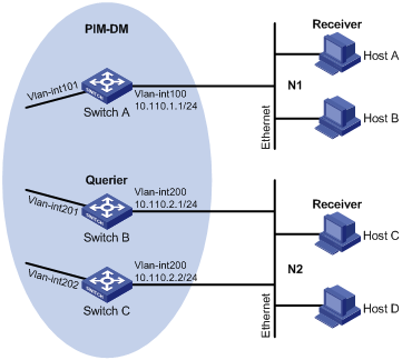
As shown in Figure 1:
· OSPF and PIM-DM run on the network.
· VOD streams are sent in multicast. Hosts of different organizations form stub networks N1 and N2.
· IGMPv2 runs between Switch A and N1, and between the other two switches and N2. Switch A acts as the IGMP querier in N1. Switch B acts as the IGMP querier in N2 because it has a lower IP address.
Configure basic IGMP features on the switches to meet the following requirements:
· Hosts in N1 can join any multicast groups.
· Hosts in N2 can join only multicast group 224.1.1.1.

Analysis
To limit the multicast groups that hosts can join, create an IPv4 basic ACL and specify the multicast groups that you want the hosts to join.
Applicable hardware and software versions
The following matrix shows the hardware and software versions to which this configuration example is applicable:
|
Hardware |
Software version |
|
S6850 switch series S9850 switch series |
Release 6555P01 |
|
S9820-64H switch |
Release 6555P01 |
Restrictions and guidelines
When you configure basic IGMP features, follow these restrictions and guidelines:
· The protocol packets of different IGMP versions are different in structures and types. For IGMP to operate correctly, you must enable the same IGMP version for all switches on the same subnet.
· You must configure the same multicast group policy for all switches on the same subnet.
· By default, Ethernet interfaces, VLAN interfaces, and aggregate interfaces are shut down. You must first use the undo shutdown command to bring them up. This example assumes that all these interfaces are already up.
Procedures
1. Assign an IP address and subnet mask to each interface, as shown in Figure 1. (Details not shown.)
2. Configure OSPF on the switches in the PIM-DM domain. (Details not shown.)
3. Configure Switch A:
# Enable IP multicast routing.
<SwitchA> system-view
[SwitchA] multicast routing
[SwitchA-mrib] quit
# Enable IGMP on the receiver-side interface VLAN-interface 100.
[SwitchA] interface vlan-interface 100
[SwitchA-Vlan-interface100] igmp enable
[SwitchA-Vlan-interface100] quit
# Enable PIM-DM on VLAN-interface 101.
[SwitchA] interface vlan-interface 101
[SwitchA-Vlan-interface101] pim dm
[SwitchA-Vlan-interface101] quit
4. Configure Switch B:
# Create ACL 2001 to permit IGMP reports for multicast group 224.1.1.1.
<SwitchB> system-view
[SwitchB] acl basic 2001
[SwitchB-acl-ipv4-basic-2001] rule permit source 224.1.1.1 0
[SwitchB-acl-ipv4-basic-2001] quit
# Enable IP multicast routing.
[SwitchB] multicast routing
[SwitchB-mrib] quit
# Enable IGMP on the receiver-side interface VLAN-interface 200.
[SwitchB] interface vlan-interface 200
[SwitchB-Vlan-interface200] igmp enable
# Configure a multicast group policy that uses ACL 2001.
[SwitchB-Vlan-interface200] igmp group-policy 2001
[SwitchB-Vlan-interface200] quit
# Enable PIM-DM on VLAN-interface 201.
[SwitchB] interface vlan-interface 201
[SwitchB-Vlan-interface201] pim dm
[SwitchB-Vlan-interface201] quit
5. Configure Switch C:
# Create ACL 2001 to permit IGMP reports for multicast group 224.1.1.1.
<SwitchC> system-view
[SwitchC] acl basic 2001
[SwitchC-acl-ipv4-basic-2001] rule permit source 224.1.1.1 0
[SwitchC-acl-ipv4-basic-2001] quit
# Enable IP multicast routing.
[SwitchC] multicast routing
[SwitchC-mrib] quit
# Enable IGMP on the receiver-side interface VLAN-interface 200.
[SwitchC] interface vlan-interface 200
[SwitchC-Vlan-interface200] igmp enable
# Configure a multicast group policy that uses ACL 2001.
[SwitchC-Vlan-interface200] igmp group-policy 2001
[SwitchC-Vlan-interface200] quit
# Enable PIM-DM on VLAN-interface 202.
[SwitchC] interface vlan-interface 202
[SwitchC-Vlan-interface202] pim dm
[SwitchC-Vlan-interface202] quit
Verifying the configuration
1. Verify that hosts in N1 can join the multicast groups 224.1.1.1 and 224.1.1.2:
# Send IGMP reports from Host A (10.110.1.10) to join the multicast groups 224.1.1.1 and 224.1.1.2. (Details not shown.)
# Display information about IGMP groups that hosts have dynamically joined on Switch A.
[SwitchA] display igmp group
IGMP groups in total: 2
Vlan-interface100 (10.110.1.1):
IGMP groups reported in total: 2
Group address Last reporter Uptime Expires
224.1.1.1 10.110.1.10 00:02:04 00:01:15
224.1.1.2 10.110.1.10 00:02:00 00:01:19
The output shows that Host A has joined the multicast groups 224.1.1.1 and 224.1.1.2.
2. Verify that hosts in N2 can join only multicast group 224.1.1.1:
# Send IGMP reports from Host C (10.110.2.10) to join the multicast groups 224.1.1.1 and 224.1.1.2. (Details not shown.)
# Display information about IGMP groups that hosts have dynamically joined on Switch B.
[SwitchB] display igmp group
IGMP groups in total: 1
Vlan-interface200(10.110.2.1):
IGMP groups reported in total: 1
Group address Last reporter Uptime Expires
224.1.1.1 10.110.2.10 04:36:03 00:01:23
# Display information about IGMP groups that hosts have dynamically joined on Switch C.
[SwitchC] display igmp group
IGMP groups in total: 1
Vlan-interface200(10.110.2.2):
IGMP groups reported in total: 1
Group address Last reporter Uptime Expires
224.1.1.1 10.110.2.10 04:21:03 00:01:13
The output shows that Switch B and Switch C each have IGMP information about only the multicast group, 224.1.1.1. The multicast group policy has taken effect, and hosts in N2 can join only multicast group 224.1.1.1.
Configuration files
· Switch A:
#
vlan 100 to 101
#
interface Vlan-interface100
ip address 10.110.1.1 255.255.255.0
igmp enable
#
interface Vlan-interface101
ip address 10.111.1.1 255.255.255.0
pim dm
#
interface HundredGigE1/0/1
port link-mode bridge
port access vlan 100
#
interface HundredGigE1/0/2
port link-mode bridge
port access vlan 101
#
multicast routing
#
· Switch B:
#
acl basic 2001
rule 0 permit source 224.1.1.1 0
#
vlan 200 to 201
#
interface Vlan-interface200
ip address 10.110.2.1 255.255.255.0
igmp enable
igmp group-policy 2001
#
interface Vlan-interface201
ip address 10.111.2.1 255.255.255.0
pim dm
#
interface HundredGigE1/0/1
port link-mode bridge
port access vlan 200
#
interface HundredGigE1/0/2
port link-mode bridge
port access vlan 201
#
multicast routing
#
· Switch C:
#
acl basic 2001
rule 0 permit source 224.1.1.1 0
#
vlan 200
#
vlan 202
#
interface Vlan-interface200
ip address 10.110.2.2 255.255.255.0
igmp enable
igmp group-policy 2001
#
interface Vlan-interface202
ip address 10.111.3.1 255.255.255.0
pim dm
#
interface HundredGigE1/0/1
port link-mode bridge
port access vlan 200
#
interface HundredGigE1/0/2
port link-mode bridge
port access vlan 202
#
multicast routing
#
Example: Configuring IGMP static group members
Network configuration
As shown in Figure 2:
· OSPF and PIM-DM run on the network.
· VOD streams are sent in multicast. Hosts of different organizations form stub networks N1 and N2.
· IGMPv2 runs between Switch A and N1, and between the other two switches and N2. Switch A acts as the IGMP querier in N1. Switch B acts as the IGMP querier in N2 because it has a lower IP address.
Configure the switches to meet the following requirements:
· Hosts in N1 can join any multicast groups, and Host A can permanently receive multicast data addressed to multicast group 224.1.1.2.
· Hosts in N2 can join only multicast group 224.1.1.1.
Analysis
For Host A to permanently receive multicast data addressed to the group 224.1.1.2, configure VLAN-interface 100 on Switch A as a static member of the multicast group.
To limit the multicast groups that hosts can join, create an IPv4 basic ACL and specify the multicast groups that you want the hosts to join.
Applicable hardware and software versions
The following matrix shows the hardware and software versions to which this configuration example is applicable:
|
Hardware |
Software version |
|
S6850 switch series S9850 switch series |
Release 6555P01 |
|
S9820-64H switch |
Release 6555P01 |
Restrictions and guidelines
When you configure IGMP static group member ports, follow these restrictions and guidelines:
· The protocol packets of different IGMP versions are different in structures and types. For IGMP to operate correctly, specify the same IGMP version for all switches on the same subnet.
· You must configure the same multicast group policy for all switches on the same subnet.
· By default, Ethernet interfaces, VLAN interfaces, and aggregate interfaces are shut down. You must first use the undo shutdown command to bring them up. This example assumes that all these interfaces are already up.
Procedures
1. Assign an IP address and subnet mask to each interface, as shown in Figure 2. (Details not shown.)
2. Configure OSPF on the switches in the PIM-DM domain. (Details not shown.)
3. Configure Switch A:
# Enable IP multicast routing.
<SwitchA> system-view
[SwitchA] multicast routing
[SwitchA-mrib] quit
# Enable PIM-DM on VLAN-interface 101.
[SwitchA] interface vlan-interface 101
[SwitchA-Vlan-interface101] pim dm
[SwitchA-Vlan-interface101] quit
# Enable IGMP on the receiver-side interface VLAN-interface 100.
[SwitchA] interface vlan-interface 100
[SwitchA-Vlan-interface100] igmp enable
# Configure VLAN-interface 100 as a static member of multicast group 224.1.1.2.
[SwitchA-Vlan-interface100] igmp static-group 224.1.1.2
[SwitchA-Vlan-interface100] quit
4. Configure Switch B:
# Enable IP multicast routing.
<SwitchB> system-view
[SwitchB] multicast routing
[SwitchB-mrib] quit
# Enable PIM-DM on VLAN-interface 201.
[SwitchB] interface vlan-interface 201
[SwitchB-Vlan-interface201] pim dm
[SwitchB-Vlan-interface201] quit
# Create ACL 2001 to permit IGMP reports for multicast group 224.1.1.1.
[SwitchB] acl basic 2001
[SwitchB-acl-ipv4-basic-2001] rule permit source 224.1.1.1 0
[SwitchB-acl-ipv4-basic-2001] quit
# Enable IGMP on the receiver-side interface VLAN-interface 200.
[SwitchB] interface vlan-interface 200
[SwitchB-Vlan-interface200] igmp enable
# Configure a multicast group policy that uses ACL 2001.
[SwitchB-Vlan-interface200] igmp group-policy 2001
[SwitchB-Vlan-interface200] quit
5. Configure Switch C:
# Enable IP multicast routing.
<SwitchC> system-view
[SwitchC] multicast routing
[SwitchC-mrib] quit
# Enable PIM-DM on VLAN-interface 202.
[SwitchC] interface vlan-interface 202
[SwitchC-Vlan-interface202] pim dm
[SwitchC-Vlan-interface202] quit
# Create ACL 2001 to permit IGMP reports for multicast group 224.1.1.1.
[SwitchC] acl basic 2001
[SwitchC-acl-ipv4-basic-2001] rule permit source 224.1.1.1 0
[SwitchC-acl-ipv4-basic-2001] quit
# Enable IGMP on VLAN-interface 200.
[SwitchC] interface vlan-interface 200
[SwitchC-Vlan-interface200] igmp enable
# Configure a multicast group policy that uses ACL 2001.
[SwitchC-Vlan-interface200] igmp group-policy 2001
[SwitchC-Vlan-interface200] quit
Verifying the configuration
1. Verify that hosts in N1 can join the multicast groups 224.1.1.1 and 224.1.1.2:
# Send IGMP reports from Host A (10.110.1.10) to join the multicast groups 224.1.1.1 and 224.1.1.2. (Details not shown.)
# Display information about IGMP groups that hosts have dynamically joined on Switch A.
[SwitchA] display igmp group
IGMP groups in total: 2.
Vlan-interface100 (10.110.1.1):
IGMP groups reported in total: 2
Group address Last reporter Uptime Expires
224.1.1.1 10.110.1.10 00:02:04 00:01:15
224.1.1.2 10.110.1.10 00:02:00 00:01:19
The output shows that Host A has dynamically joined the multicast groups 224.1.1.1 and 224.1.1.2.
# Display information about IGMP groups that hosts have statically joined on Switch A.
[SwitchA] display igmp group static
Entries in total: 1
Group address Source address Interface Expires
224.1.1.2 0.0.0.0 Vlan100 Never
The output shows that Host A has statically joined multicast group 224.1.1.1 through VLAN-interface 100.
2. Verify that hosts in N2 can join only multicast group 224.1.1.1:
# Send IGMP reports from Host C (10.110.2.10) to join multicast groups 224.1.1.1 and 224.1.1.2. (Details not shown.)
# Display information about IGMP groups that hosts have dynamically joined on Switch B.
[SwitchB] display igmp group
IGMP groups in total: 1
Vlan-interface200(10.110.2.1):
IGMP groups reported in total: 1
Group address Last reporter Uptime Expires
224.1.1.1 10.110.2.10 04:36:03 00:01:23
# Display information about IGMP groups that hosts have dynamically joined on Switch C.
[SwitchC] display igmp group
IGMP groups in total: 1
Vlan-interface200(10.110.2.2):
IGMP groups reported in total: 1
Group address Last reporter Uptime Expires
224.1.1.1 10.110.2.10 04:21:03 00:01:13
The output shows that Switch B and Switch C each have information only about multicast group 224.1.1.1. The multicast group policy has taken effect, and hosts in N2 can join only multicast group 224.1.1.1.
Configuration files
· Switch A:
#
vlan 100 to 101
#
interface Vlan-interface100
ip address 10.110.1.1 255.255.255.0
igmp enable
igmp static-group 224.1.1.2
#
interface Vlan-interface101
ip address 10.111.1.1 255.255.255.0
pim dm
#
interface HundredGigE1/0/1
port link-mode bridge
port access vlan 100
#
interface HundredGigE1/0/2
port link-mode bridge
port access vlan 101
#
multicast routing
#
· Switch B:
#
acl basic 2001
rule 0 permit source 224.1.1.1 0
#
vlan 200 to 201
#
interface Vlan-interface200
ip address 10.110.2.1 255.255.255.0
igmp enable
igmp group-policy 2001
#
interface Vlan-interface201
ip address 10.111.2.1 255.255.255.0
pim dm
#
interface HundredGigE1/0/1
port link-mode bridge
port access vlan 200
#
interface HundredGigE1/0/2
port link-mode bridge
port access vlan 201
#
multicast routing
#
· Switch C:
#
acl basic 2001
rule 0 permit source 224.1.1.1 0
#
vlan 200
#
vlan 202
#
interface Vlan-interface200
ip address 10.110.2.2 255.255.255.0
igmp enable
igmp group-policy 2001
#
interface Vlan-interface202
ip address 10.111.3.1 255.255.255.0
pim dm
#
interface HundredGigE1/0/1
port link-mode bridge
port access vlan 200
#
interface HundredGigE1/0/2
port link-mode bridge
port access vlan 202
#
multicast routing
#
Example: Configuring IGMP SSM mappings
Network configuration
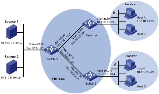
As shown in Figure 3:
· The SSM group range for the PIM-SSM domain is 232.1.1.0/24.
· Switch A and Switch B in the PIM-SSM domain run IGMPv3.
· Host A in N1 and Host B in N2 run IGMPv2, and they do not support IGMPv3. The other hosts in N1 and N2 run IGMPv3.
Configure IGMP SSM mappings on Switch A and Switch B to meet the following requirements:
· Hosts in N1 receive multicast data only from Source 1.
· Hosts in N2 receive multicast data only from Source 2.
Applicable hardware and software versions
The following matrix shows the hardware and software versions to which this configuration example is applicable:
|
Hardware |
Software version |
|
S6850 switch series S9850 switch series |
Release 6555P01 |
|
S9820-64H switch |
Release 6555P01 |
Restrictions and guidelines
By default, Ethernet interfaces, VLAN interfaces, and aggregate interfaces are shut down. You must use the undo shutdown command to bring them up. This example assumes that all these interfaces are already up.
Procedures
1. Assign an IP address and subnet mask to each interface, as shown in Figure 3. (Details not shown.)
2. Configure OSPF on the switches in the PIM-SSM domain. (Details not shown.)
3. Enable IP multicast routing and enable PIM-SM:
# On Switch A, enable IP multicast routing, and enable PIM-SM on VLAN-interface 200.
<SwitchA> system-view
[SwitchA] multicast routing
[SwitchA-mrib] quit
[SwitchA] interface vlan-interface 200
[SwitchA-Vlan-interface200] pim sm
[SwitchA-Vlan-interface200] quit
# Configure Switch B in the same way Switch A is configured. (Details not shown.)
# On Router C, enable IP multicast routing, and enable PIM-SM on each interface.
<SwitchC> system-view
[SwitchC] multicast routing
[SwitchC-mrib] quit
[SwitchC] interface vlan-interface 100
[SwitchC-Vlan-interface100] pim sm
[SwitchC-Vlan-interface100] quit
[SwitchC] interface vlan-interface 200
[SwitchC-Vlan-interface200] pim sm
[SwitchC-Vlan-interface200] quit
[SwitchC] interface vlan-interface 300
[SwitchC-Vlan-interface300] pim sm
[SwitchC-Vlan-interface300] quit
4. On Switch C, configure VLAN-interface 200 as a C-BSR and a C-RP:
[SwitchC] pim
[SwitchC-pim] c-bsr 192.168.1.1
[SwitchC-pim] c-rp 192.168.1.1
[SwitchC-pim] quit
5. Configure IGMPv3 on the receiver-side interfaces:
# On Switch A, enable IGMP, and specify IGMP version 3 on VLAN-interface 201.
[SwitchA] interface vlan-interface201
[SwitchA-Vlan-interface201] igmp enable
[SwitchA-Vlan-interface201] igmp version 3
[SwitchA-Vlan-interface201] quit
# Configure Switch B in the same way Switch A is configured. (Details not shown.)
6. Configure the SSM group range:
# On Switch A, configure the SSM group range as 232.1.1.0/24.
[SwitchA] acl basic 2000
[SwitchA-acl-ipv4-basic-2000] rule permit source 232.1.1.0 0.0.0.255
[SwitchA-acl-ipv4-basic-2000] quit
[SwitchA] pim
[SwitchA-pim] ssm-policy 2000
[SwitchA-pim] quit
# Configure Switch B and Switch C in the same way Switch A is configured. (Details not shown.)
7. Configure IGMP SSM mappings:
# On Switch A, configure an IGMP SSM mapping with multicast source 10.110.5.100 and multicast group range 232.1.1.0/24 specified in ACL 2000.
[SwitchA] igmp
[SwitchA-igmp] ssm-mapping 10.110.5.100 2000
[SwitchA-igmp] quit
# On Switch B, configure an IGMP SSM mapping with multicast source 10.110.5.101 and multicast group range 232.1.1.0/24 specified in ACL 2000.
[SwitchB] igmp
[SwitchB-igmp] ssm-mapping 10.110.5.101 2000
[SwitchB-igmp] quit
Verifying the configuration
# Send IGMPv2 reports from Host A and Host C to join multicast group 232.1.1.1. (Details not shown.)
# Send multicast data from Source 1 and Source 2 to multicast group 232.1.1.1. (Details not shown.)
# Display IGMP SSM mappings for multicast group 232.1.1.1 on Switch A.
[SwitchA] display igmp ssm-mapping 232.1.1.1
Group: 232.1.1.1
Source list:
10.110.5.100
The output shows that multicast group 232.1.1.1 is associated with Source 1 (10.110.5.100). Switch A will translate (0.0.0.0, 232.1.1.1) in IGMPv2 reports to (10.110.5.100, 232.1.1.1).
# Display the PIM routing table on Switch A.
[SwitchA] display pim routing-table
Total 0 (*, G) entries; 1 (S, G) entries
(10.110.5.100, 232.1.1.1)
Protocol: pim-ssm, Flag:
UpTime: 00:13:25
Upstream interface: Vlan-interface200
Upstream neighbor: 192.168.1.1
RPF prime neighbor: 192.168.1.1
Downstream interface(s) information:
Total number of downstreams: 1
1: Vlan-interface201
Protocol: igmp, UpTime: 02:54:43, Expires: 00:02:47
The output shows that Switch A has the (10.110.5.100, 232.1.1.1) entry.
# Display IGMP SSM mappings for multicast group 232.1.1.1 on Switch B.
[SwitchB] display igmp ssm-mapping 232.1.1.1
Group: 232.1.1.1
Source list:
10.110.5.101
The output shows that multicast group 232.1.1.1 is associated with Source 2 (10.110.5.101). Switch B will translate (0.0.0.0, 232.1.1.1) in IGMPv2 reports to (10.101.5.101, 232.1.1.1).
# Display the PIM routing table on Switch B.
[SwitchB] display pim routing-table
Total 0 (*, G) entries; 1 (S, G) entries
(10.110.5.101, 232.1.1.1)
Protocol: pim-ssm, Flag:
UpTime: 00:12:16
Upstream interface: Vlan-interface300
Upstream neighbor: 192.168.2.1
RPF prime neighbor: 192.168.2.1
Downstream interface(s) information:
Total number of downstreams: 1
1: Vlan-interface301
Protocol: igmp, UpTime: 02:54:43, Expires: 00:02:47
The output shows that Switch B has the (10.110.5.101, 232.1.1.1) entry.
Configuration files
· Switch A:
#
interface Vlan-interface200
pim sm
#
interface Vlan-interface201
igmp enable
igmp version 3
#
multicast routing
#
pim
ssm-policy 2000
#
igmp
ssm-mapping 10.110.5.100 2000
#
acl basic 2000
rule 0 permit source 232.1.1.0 0.0.0.255
#
· Switch B:
#
interface Vlan-interface300
pim sm
#
interface Vlan-interface301
igmp enable
igmp version 3
#
multicast routing
#
pim
ssm-policy 2000
#
igmp
ssm-mapping 10.110.5.100 2000
#
acl basic 2000
rule 0 permit source 232.1.1.0 0.0.0.255
#
· Switch C:
#
interface Vlan-interface100
pim sm
#
interface Vlan-interface200
pim sm
#
interface Vlan-interface200
pim sm
#
multicast routing
#
pim
c-bsr 192.168.1.1
c-rp 192.168.1.1
#
Related documentation
· H3C S6850 & S9850 Switch Series IP Multicast Configuration Guide-Release 655x
· H3C S6850 & S9850 Switch Series IP Multicast Command Reference-Release 655x
· H3C S9820-64H Switch IP Multicast Configuration Guide-Release 655x
· H3C S9820-64H Switch IP Multicast Command Reference-Release 655x
·