- Table of Contents
-
- H3C S6850&S9850&S9820-64H Config Examples-Release 655x-6W100
- 01-Login Management Configuration Examples
- 02-RBAC Configuration Examples
- 03-Software Upgrade Examples
- 04-ISSU Configuration Examples
- 05-Software Patching Examples
- 06-Ethernet Link Aggregation Configuration Examples
- 07-Port Isolation Configuration Examples
- 08-Spanning Tree Configuration Examples
- 09-VLAN Configuration Examples
- 10-VLAN Tagging Configuration Examples
- 11-DHCP Snooping Configuration Examples
- 12-Cross-Subnet Dynamic IP Address Allocation Configuration Examples
- 13-IPv6 over IPv4 Manual Tunneling with OSPFv3 Configuration Examples
- 14-ISATAP Tunnel and 6to4 Tunnel Configuration Examples
- 15-GRE Tunnel Configuration Examples
- 16-GRE with OSPF Configuration Examples
- 17-OSPF Configuration Examples
- 18-IS-IS Configuration Examples
- 19-BGP Configuration Examples
- 20-Policy-Based Routing Configuration Examples
- 21-OSPFv3 Configuration Examples
- 22-IPv6 IS-IS Configuration Examples
- 23-Routing Policy Configuration Examples
- 24-IGMP Snooping Configuration Examples
- 25-IGMP Configuration Examples
- 26-BIDIR-PIM Configuration Examples
- 27-MLD Snooping Configuration Examples
- 28-IPv6 Multicast VLAN Configuration Examples
- 29-Basic MPLS Configuration Examples
- 30-MPLS L3VPN Configuration Examples
- 31-ACL Configuration Examples
- 32-Control Plane-Based QoS Policy Configuration Examples
- 33-Traffic Policing Configuration Examples
- 34-GTS and Rate Limiting Configuration Examples
- 35-Priority Mapping and Queue Scheduling Configuration Examples
- 36-Traffic Filtering Configuration Examples
- 37-AAA Configuration Examples
- 38-Port Security Configuration Examples
- 39-Portal Configuration Examples
- 40-SSH Configuration Examples
- 41-IP Source Guard Configuration Examples
- 42-Ethernet OAM Configuration Examples
- 43-CFD Configuration Examples
- 44-DLDP Configuration Examples
- 45-VRRP Configuration Examples
- 46-BFD Configuration Examples
- 47-NTP Configuration Examples
- 48-SNMP Configuration Examples
- 49-NQA Configuration Examples
- 50-Mirroring Configuration Examples
- 51-sFlow Configuration Examples
- 52-FCoE Configuration Examples
- 53-OpenFlow Configuration Examples
- 54-MAC Address Table Configuration Examples
- 55-Static Multicast MAC Address Entry Configuration Examples
- 56-IP Unnumbered Configuration Examples
- 57-MVRP Configuration Examples
- 58-MCE Configuration Examples
- 59-Congestion Avoidance and Queue Scheduling Configuration Examples
- 60-Attack Protection Configuration Examples
- 61-Smart Link Configuration Examples
- 62-RRPP Configuration Examples
- 63-BGP Route Selection Configuration Examples
- 64-IS-IS Route Summarization Configuration Examples
- 65-IRF Configuration Examples
- 66-MPLS OAM Configuration Examples
- 67-MPLS TE Configuration Examples
- 68-VXLAN Configuration Examples
- 69-NetStream Configuration Examples
- 70-DRNI Configuration Examples
- 71-DRNI and EVPN Configuration Examples
- 72-EVPN-DCI over an MPLS L3VPN Network Configuration Examples
- 73-VCF Fabric Configuration Examples
- 74-PTP Configuration Examples
- 75-S-MLAG Configuration Examples
- 76-Puppet Configuration Examples
- Related Documents
-
| Title | Size | Download |
|---|---|---|
| 65-IRF Configuration Examples | 636.56 KB |
|
|
|
H3C S6850 & S9850 & S9820-64H |
|
IRF Configuration Examples |
|
|
Copyright © 2020 New H3C Technologies Co., Ltd. All rights reserved.
No part of this manual may be reproduced or transmitted in any form or by any means without prior written consent of New H3C Technologies Co., Ltd.
Except for the trademarks of New H3C Technologies Co., Ltd., any trademarks that may be mentioned in this document are the property of their respective owners.
The information in this document is subject to change without notice.
Contents
General restrictions and guidelines
Feature compatibility and configuration restrictions
IRF physical interface requirements
Example: Setting up a four-chassis LACP MAD-enabled IRF fabric
Network connectivity configuration
Applicable hardware and software versions
Setting up the access-layer IRF fabric
Configuring network connectivity settings
Verifying the link backup function of multichassis aggregations
Verifying link failure protection of the ring topology
Verifying the LACP MAD configuration
Example: Setting up a four-chassis BFD MAD-enabled IRF fabric
Network connectivity configuration
Applicable hardware and software versions
Configuring network connectivity settings
Verifying the routing configuration
Verifying the link backup function of multichassis aggregations
Verifying link failure protection of the ring topology
Verifying the BFD MAD configuration
Applicable hardware and software versions
Management IP address configuration restrictions and guidelines
ARP MAD configuration restrictions and guidelines
Configuring management IP addresses
Applicable hardware and software versions
Management IP address configuration restrictions and guidelines
BFD MAD configuration restrictions and guidelines
Configuring management IP addresses
Introduction
This document provides examples for setting up IRF fabrics and configuring link aggregation and routing on the IRF fabrics.
Prerequisites
The configuration examples in this document were created and verified in a lab environment, and all the devices were started with the factory default configuration. When you are working on a live network, make sure you understand the potential impact of every command on your network.
This document assumes that you have basic knowledge of IRF.
General restrictions and guidelines
When you set up and configure an IRF fabric, follow the restrictions and guidelines in this section.
This section provides only the basic restrictions and guidelines that ensure a successful IRF deployment. For complete information, see IRF configuration guide for the switch.
Hardware requirements
You can establish an IRF fabric by using S6850 switches, S9850 switches, or switches from both series.
An S9820-64H switch can form an IRF fabric only with devices of the same model.
Software requirements
All IRF member devices must run the same system software version.
Feature compatibility and configuration restrictions
Make sure the feature settings in Table 1 are the same across member devices.
Table 1 IRF and feature compatibility
|
Feature |
Command |
|
Enhanced ECMP mode. |
ecmp mode enhanced |
|
Table capacity mode. |
hardware-resource switch-mode |
|
Support for the IPv6 routes with prefixes longer than 64 bits. |
hardware-resource routing-mode |
|
System operating mode. |
system-working-mode |
|
Enabling status of the packet loss prevention feature for OpenFlow forwarding. |
openflow lossless enable |
|
VXLAN hardware resource mode. (Available only on the S6850 and S9850 switch series.) |
hardware-resource vxlan |
IRF physical interface requirements
S6850 and S9850 switch series
The S6850 and S9850 switch series support only 40G and 100G IRF links. On these switches, use any QSFP+ operating at 40 Gbps or QSFP28 ports operating at 40 Gbps or 100 Gbps to establish IRF links, except the ports on the LSWM18CQMSEC interface module.
When you select transceiver modules and cables, follow these restrictions and guidelines:
· Use the following media to connect IRF physical interfaces for a long-distance connection:
¡ QSFP28 transceiver modules and fibers.
¡ QSFP+ transceiver modules and fibers.
· Use the following media to connect IRF physical interfaces for a short-distance connection:
¡ QSFP28 optical cables.
¡ QSFP28 DAC cables.
¡ QSFP+ optical cables.
¡ QSFP+ DAC cables.
· The transceiver modules at the two ends of an IRF link must be the same type.
When you use QSFP+ DAC cables to connect IRF physical interfaces, follow these restrictions and guidelines:
· The IRF physical interfaces at the two ends of an IRF physical link must both be fixed ports or ports on interface modules. Do not connect a fixed port to a port on an interface module for IRF connection. However, you can bind fixed ports and ports on an interface module to the same IRF port.
· If you use ports on interface modules as IRF physical interfaces, make sure the interface modules at the two ends of a physical IRF link are the same type.
· To use a fixed QSFP28 port on the rear panel of an S6850-2C member as an IRF physical interface, you must make sure its IRF neighbor is also an S6850-2C switch. In addition, you can connect that port only to a fixed QSFP28 port on the rear panel of the neighboring S6850-2C switch.
S9820-64H switch
Use the QSFP28 ports on the front panel of the S9820-64H switch as IRF physical interfaces. The 10-GE or 25-GE breakout interfaces of a QSFP28 port cannot be used as IRF physical interfaces.
When you select transceiver modules and cables, follow these restrictions and guidelines:
· Use QSFP28 transceiver modules and fibers to connect IRF physical interfaces for a long-distance connection.
· Use QSFP28 optical or DAC cables to connect IRF physical interfaces for a short-distance connection.
· The transceiver modules at the two ends of an IRF link must be the same type.
Connecting IRF ports
When you connect two neighboring IRF members, connect the physical interfaces of IRF-port 1 on one member to the physical interfaces of IRF-port 2 on the other.
Licensing requirements
For a license-based feature to run correctly on an IRF fabric, make sure the licenses installed for the feature on all member devices are the same. For more information about feature licensing, see Fundamentals Configuration Guide.
Example: Setting up a four-chassis LACP MAD-enabled IRF fabric
Network configuration
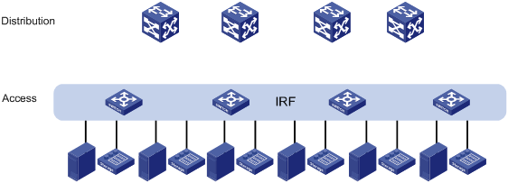
As shown in Figure 2, use a four-chassis IRF fabric to replace the ToR switches in Figure 1 at the access layer of the data center. The access-layer IRF fabric provides Layer 2 forwarding services.
Run LACP MAD to detect IRF split.
Figure 1 Network diagram before IRF deployment
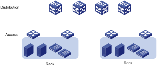
Figure 2 Network diagram after IRF deployment
Analysis
The requirements in this example include the following categories:
· Network connectivity configuration
IRF setup
To set up an IRF fabric, determine the items in Table 2.
|
Item |
Analysis |
Choice in this example |
|
Topology |
You can use a ring or daisy-chain topology for a three- or four-chassis IRF fabric. For reliability, use the ring topology. |
Ring topology (see Figure 3). |
|
Member ID assignment |
IRF member IDs must be unique. |
Device A—1. Device B—2. Device C—3. Device D—4. |
|
Master device |
IRF members elect a master automatically. For a member device to be elected the master, assign it the highest member priority. |
Device A. |
|
IRF port bindings |
Make sure the IRF port bindings are consistent with the physical connections. For high availability, bind multiple physical interfaces to an IRF port. These ports will automatically aggregate for load balancing and redundancy. |
See Table 3. |
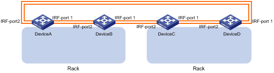
Table 3 IRF physical interface bindings
|
IRF physical interfaces |
|
|
Device A: |
|
|
IRF-port 1 |
HundredGigE 1/0/25 HundredGigE 1/0/26 |
|
IRF-port 2 |
HundredGigE 1/0/27 HundredGigE 1/0/28 |
|
Device B: |
|
|
IRF-port 1 |
HundredGigE 2/0/25 HundredGigE 2/0/26 |
|
IRF-port 2 |
HundredGigE 2/0/27 HundredGigE 2/0/28 |
|
Device C: |
|
|
IRF-port 1 |
HundredGigE 3/0/25 HundredGigE 3/0/26 |
|
IRF-port 2 |
HundredGigE 3/0/27 HundredGigE 3/0/28 |
|
Device D: |
|
|
IRF-port 1 |
HundredGigE 4/0/25 HundredGigE 4/0/26 |
|
IRF-port 2 |
HundredGigE 4/0/27 HundredGigE 4/0/28 |
|
|
NOTE: The first segment in a physical interface number is the IRF member ID. By default, the IRF member ID is 1. Table 3 shows the interface numbers after the member IDs are changed. |
LACP MAD configuration
|
|
IMPORTANT: For LACP MAD to run correctly, you must make sure the intermediate device supports extended LACPDUs for LACP MAD. |
To run LACP MAD, the IRF fabric and intermediate device must each have a dynamic Ethernet link aggregation. LACP MAD cannot run on a static link aggregation.
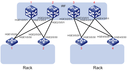
If the intermediate device is also an IRF fabric, you must configure MAD for both IRF fabrics, and assign the two IRF fabrics different domain IDs for correct split detection. This example uses a four-chassis IRF fabric at the distribution layer. The access-layer and distribution-layer IRF fabrics are the intermediate device of each other, as shown in Figure 4.
In this example, each member in the access-layer IRF fabric has only two links to the distribution-layer IRF fabric. For high availability, you can connect each member in the access-layer IRF fabric to each member in the distribution-layer IRF fabric. After you aggregate these links, they are regarded as one link in the topology.
For quick split detection, assign high-speed ports for uplink aggregation connections. This example uses 100-GE ports.
Network connectivity configuration
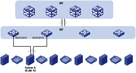
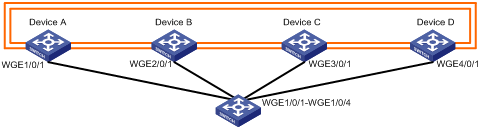
In a Layer 2 network, IRF is typically used with link aggregation to simplify the network topology.
For high availability, you can connect each host or server to two ToR switches in the access-layer IRF fabric, and aggregate the links. On each link aggregation, you do not need to run the spanning tree protocol feature because an IRF fabric appears as one node in the network.
For VLAN tags to be processed correctly, assign ports and aggregate interfaces to the correct VLANs.
|
|
NOTE: A link aggregation could span one member device, some of the member devices, or all member devices, depending on the link redundancy requirements and number of available links. The link aggregation used for LACP MAD must span all member devices. |
Figure 5 Connection diagram for the IRF fabrics in a Layer 2 network
Applicable hardware and software versions
The following matrix shows the hardware and software versions to which this configuration example is applicable:
|
Hardware |
Software version |
|
S6850 switch series S9850 switch series |
Release 6555P01 |
|
S9820-64H switch |
Release 6555P01 |
Restrictions and guidelines
When you configure LACP MAD, follow these restrictions and guidelines:
· You only need to run LACP MAD on a single link aggregation for IRF split detection.
· The link aggregation must use dynamic aggregation mode.
· The link aggregation must have a minimum of one member link from each member device.
Procedures
This example assumes that the distribution-layer IRF fabric has been set up.
Setting up the access-layer IRF fabric
1. Configure Device A:
# Shut down the physical interfaces used for IRF connection. This example uses HundredGigE 1/0/25 to HundredGigE 1/0/28 for IRF connection.
<DeviceA> system-view
[DeviceA] interface range hundredgige 1/0/25 to hundredgige 1/0/28
[DeviceA-if-range] shutdown
[DeviceA-if-range] quit
# Bind HundredGigE 1/0/25 and HundredGigE 1/0/26 to IRF-port 1/1.
[DeviceA] irf-port 1/1
[DeviceA-irf-port1/1] port group interface hundredgige 1/0/25
[DeviceA-irf-port1/1] port group interface hundredgige 1/0/26
[DeviceA-irf-port1/1] quit
# Bind HundredGigE 1/0/27 and HundredGigE 1/0/28 to IRF-port 1/2.
[DeviceA] irf-port 1/2
[DeviceA-irf-port1/2] port group interface hundredgige 1/0/27
[DeviceA-irf-port1/2] port group interface hundredgige 1/0/28
[DeviceA-irf-port1/2] quit
# Bring up the physical interfaces.
[DeviceA] interface range hundredgige 1/0/25 to hundredgige 1/0/28
[DeviceA-if-range] undo shutdown
[DeviceA-if-range] quit
# Assign IRF member priority 31 to Device A. This priority is high enough to ensure that Device A can be elected as the master.
[DeviceA] irf member 1 priority 31
# Save the running configuration.
[DeviceA] quit
<DeviceA> save
# Activate the IRF port configuration.
<DeviceA> system-view
[DeviceA] irf-port-configuration active
2. Configure Device B:
# Assign member ID 2 to Device B, and reboot the device to have the change take effect.
<DeviceB> system-view
[DeviceB] irf member 1 renumber 2
Renumbering the member ID may result in configuration change or loss. Continue? [Y/N]:y
[DeviceB] quit
<DeviceB> reboot
# Shut down the physical interfaces used for IRF connection. This example uses HundredGigE 2/0/25 to HundredGigE 2/0/28 for IRF connection.
<DeviceB> system-view
[DeviceB] interface range hundredgige 2/0/25 to hundredgige 2/0/28
[DeviceB-if-range] shutdown
[DeviceB-if-range] quit
# Bind HundredGigE 2/0/25 and HundredGigE 2/0/26 to IRF-port 2/1.
[DeviceB] irf-port 2/1
[DeviceB-irf-port2/1] port group interface hundredgige 2/0/25
[DeviceB-irf-port2/1] port group interface hundredgige 2/0/26
[DeviceB-irf-port2/1] quit
# Bind HundredGigE 2/0/27 and HundredGigE 2/0/28 to IRF-port 2/2.
[DeviceB] irf-port 2/2
[DeviceB-irf-port2/2] port group interface hundredgige 2/0/27
[DeviceB-irf-port2/2] port group interface hundredgige 2/0/28
[DeviceB-irf-port2/2] quit
# Bring up the physical interfaces.
[DeviceB] interface range hundredgige 2/0/25 to hundredgige 2/0/28
[DeviceB-if-range] undo shutdown
[DeviceB-if-range] quit
# Save the running configuration.
[DeviceB] quit
<DeviceB> save
# Connect Device B to Device A, as shown in Figure 3.
# Activate the IRF port configuration.
<DeviceB> system-view
[DeviceB] irf-port-configuration active
Device B has a lower priority than Device A, and Device B fails master election and reboots. A two-chassis IRF fabric is formed.
3. Configure Device C:
# Assign member ID 3 to Device C, and reboot the device to have the change take effect.
<DeviceC> system-view
[DeviceC] irf member 1 renumber 3
Renumbering the member ID may result in configuration change or loss. Continue? [Y/N]:y
[DeviceC] quit
<DeviceC> reboot
# Shut down the physical interfaces used for IRF connection. This example uses HundredGigE 3/0/25 to HundredGigE 3/0/28 for IRF connection.
<DeviceC> system-view
[DeviceC] interface range hundredgige 3/0/25 to hundredgige 3/0/28
[DeviceC-if-range] shutdown
[DeviceC-if-range] quit
# Bind HundredGigE 3/0/25 and HundredGigE 3/0/26 IRF-port 3/1.
[DeviceC] irf-port 3/1
[DeviceC-irf-port3/1] port group interface hundredgige 3/0/25
[DeviceC-irf-port3/1] port group interface hundredgige 3/0/26
[DeviceC-irf-port3/1] quit
# Bind HundredGigE 3/0/27 and HundredGigE 3/0/28 to IRF-port 3/2.
[DeviceC] irf-port 3/2
[DeviceC-irf-port3/2] port group interface hundredgige 3/0/27
[DeviceC-irf-port3/2] port group interface hundredgige 3/0/28
[DeviceC-irf-port3/2] quit
# Bring up the physical interfaces.
[DeviceC] interface range hundredgige 3/0/25 to hundredgige 3/0/28
[DeviceC-if-range] undo shutdown
[DeviceC-if-range] quit
# Save the running configuration.
[DeviceC] quit
<DeviceC> save
# Connect Device C to Device B, as shown in Figure 3.
# Activate the IRF port configuration.
<DeviceC> system-view
[DeviceC] irf-port-configuration active
Device C reboots to join the IRF fabric. A three-chassis IRF fabric is formed.
4. Configure Device D:
# Assign member ID 4 to Device D, and reboot the device to have the change take effect.
<DeviceD> system-view
[DeviceD] irf member 1 renumber 4
Renumbering the member ID may result in configuration change or loss. Continue? [Y/N]:y
[DeviceD] quit
<DeviceD> reboot
# Shut down the physical interfaces used for IRF connection. This example uses HundredGigE 4/0/25 to HundredGigE 4/0/28 for IRF connection.
<DeviceD> system-view
[DeviceD] interface range hundredgige 4/0/25 to hundredgige 4/0/28
[DeviceD-if-range] shutdown
[DeviceD-if-range] quit
# Bind HundredGigE 4/0/25 and HundredGigE 4/0/26 to IRF-port 4/1.
[DeviceD] irf-port 4/1
[DeviceD-irf-port4/1] port group interface hundredgige 4/0/25
[DeviceD-irf-port4/1] port group interface hundredgige 4/0/26
[DeviceD-irf-port4/1] quit
# Bind HundredGigE 4/0/27 and HundredGigE 4/0/28 to IRF-port 4/2.
[DeviceD] irf-port 4/2
[DeviceD-irf-port4/2] port group interface hundredgige 4/0/27
[DeviceD-irf-port4/2] port group interface hundredgige 4/0/28
[DeviceD-irf-port4/2] quit
# Bring up the physical interfaces.
[DeviceD] interface range hundredgige 4/0/25 to hundredgige 4/0/28
[DeviceD-if-range] undo shutdown
[DeviceD-if-range] quit
# Save the running configuration.
[DeviceD] quit
<DeviceD> save
# Connect Device D to Device A and Device C, as shown in Figure 3.
# Activate the IRF port configuration.
<DeviceD> system-view
[DeviceD] irf-port-configuration active
Device D reboots to join the IRF fabric. A four-chassis IRF fabric is formed. The command prompt changes to the name of Device A (the master).
5. Change the name of the IRF fabric.
<DeviceA> system-view
[DeviceA] sysname IRF
[IRF]
Configuring LACP MAD
1. Configure the IRF fabric at the access layer:
# Assign domain ID 1 to the IRF fabric.
<IRF> system-view
[IRF] irf domain 1
# Create Bridge-Aggregation 2, set its aggregation mode to dynamic, and enable LACP MAD.
[IRF] interface bridge-aggregation 2
[IRF-Bridge-Aggregation2] link-aggregation mode dynamic
[IRF-Bridge-Aggregation2] mad enable
You need to assign a domain ID (range: 0-4294967295)
[Current domain is: 1]:
The assigned domain ID is: 1
[IRF-Bridge-Aggregation2] quit
# Create a named interface range that contains uplink ports to the distribution layer IRF fabric. In this example, the interface range name is lacp, and each member device has two links to the distribution layer IRF fabric.
[IRF] interface range name lacp interface hundredgige 1/0/29 to hundredgige 1/0/30 hundredgige 2/0/29 to hundredgige 2/0/30 hundredgige 3/0/29 to hundredgige 3/0/30 hundredgige 4/0/29 to hundredgige 4/0/30
# Assign the ports in the interface range to Bridge-Aggregation 2.
[IRF-if-range-lacp] port link-aggregation group 2
[IRF-if-range-lacp] quit
2. Configure the IRF fabric at the distribution layer:
# Assign IRF domain ID 2 to the IRF fabric.
<Sysname> system-view
[Sysname] irf domain 2
# Create Bridge-Aggregation 2, set its aggregation mode to dynamic, and enable LACP MAD.
[Sysname] interface bridge-aggregation 2
[Sysname-Bridge-Aggregation2] link-aggregation mode dynamic
[Sysname-Bridge-Aggregation2] mad enable
You need to assign a domain ID (range: 0-4294967295)
[Current domain is: 2]:
The assigned domain ID is: 2
[Sysname-Bridge-Aggregation2] quit
# Assign the downlink ports that connect to the access-layer IRF fabric to Bridge-Aggregation 2.
[Sysname] interface hundredgige 1/2/0/1
[Sysname-HundredGigE1/2/0/1] port link-aggregation group 2
[Sysname-HundredGigE1/2/0/1] quit
[Sysname] interface hundredgige 1/3/0/1
[Sysname-HundredGigE1/3/0/1] port link-aggregation group 2
[Sysname-HundredGigE1/3/0/1] quit
[Sysname] interface hundredgige 2/2/0/1
[Sysname-HundredGigE2/2/0/1] port link-aggregation group 2
[Sysname-HundredGigE2/2/0/1] quit
[Sysname] interface hundredgige 2/3/0/1
[Sysname-HundredGigE2/3/0/1] port link-aggregation group 2
[Sysname-HundredGigE2/3/0/1] quit
[Sysname] interface hundredgige 3/2/0/1
[Sysname-HundredGigE3/2/0/1] port link-aggregation group 2
[Sysname-HundredGigE3/2/0/1] quit
[Sysname] interface hundredgige 3/3/0/1
[Sysname-HundredGigE3/3/0/1] port link-aggregation group 2
[Sysname-HundredGigE3/3/0/1] quit
[Sysname] interface hundredgige 4/2/0/1
[Sysname-HundredGigE4/2/0/1] port link-aggregation group 2
[Sysname-HundredGigE4/2/0/1] quit
[Sysname] interface hundredgige 4/3/0/1
[Sysname-HundredGigE4/3/0/1] port link-aggregation group 2
[Sysname-HundredGigE4/3/0/1] quit
Configuring network connectivity settings
This section provides the VLAN and link aggregation configuration procedure for end devices (for example, a server in VLAN 10).
1. Configure the IRF fabric at the access layer:
# Create VLAN 10.
<IRF> system-view
[IRF] vlan 10
# Create Bridge-Aggregation 3, and set its aggregation mode to dynamic.
[IRF] interface bridge-aggregation 3
[IRF-Bridge-Aggregation3] link-aggregation mode dynamic
[IRF-Bridge-Aggregation3] quit
# Assign Twenty-FiveGigE 1/0/10 and Twenty-FiveGigE 2/0/10 to the aggregation group for Bridge-Aggregation 3.
[IRF] interface twenty-fivegige 1/0/10
[IRF-Twenty-FiveGigE1/0/10] port link-aggregation group 3
[IRF-Twenty-FiveGigE1/0/10] quit
[IRF] interface twenty-fivegige 2/0/10
[IRF-Twenty-FiveGigE2/0/10] port link-aggregation group 3
[IRF-Twenty-FiveGigE2/0/10] quit
# Assign Bridge-Aggregation 3 to VLAN 10.
[IRF] interface bridge-aggregation 3
[IRF-Bridge-Aggregation3] port access vlan 10
[IRF-Bridge-Aggregation3] quit
# Configure Bridge-Aggregation 2 as a trunk port, and assign it to VLAN 10.
[IRF] interface bridge-aggregation 2
[IRF-Bridge-Aggregation2] port link-type trunk
[IRF-Bridge-Aggregation2] port trunk permit vlan 10
[IRF-Bridge-Aggregation2] quit
# Save the running configuration to the next-startup configuration file.
[IRF] save
2. Configure the IRF fabric at the distribution layer:
# Create VLAN 10.
<Sysname> system-view
[Sysname] vlan 10
# Configure Bridge-Aggregation 2 as a trunk port, and assign it to VLAN 10.
[Sysname] interface bridge-aggregation 2
[Sysname-Bridge-Aggregation2] port link-type trunk
[Sysname-Bridge-Aggregation2] port trunk permit vlan 10
[Sysname-Bridge-Aggregation2] quit
Verifying the configuration
Verify the IRF setup, multichassis link aggregations, ring topology, and LACP MAD.
Verifying the IRF setup
# Verify that the IRF fabric has been formed.
[IRF] display irf
MemberID Role Priority CPU-Mac Description
*+1 Master 31 00e0-fc0f-8c02 ---
2 Standby 1 00e0-fc0f-8c03 ---
3 Standby 1 00e0-fc0f-8c04 ---
4 Standby 1 00e0-fc0f-8c05 ---
--------------------------------------------------
* indicates the device is the master.
+ indicates the device through which the user logs in.
The Bridge MAC of the IRF is: 0cda-414a-859b
Auto upgrade : yes
Mac persistent : 12 min
Domain ID : 1
The output shows that the IRF fabric has four member devices.
# Verify IRF fabric connectivity.
[IRF] display irf topology
Topology Info
-------------------------------------------------------------------------
IRF-Port1 IRF-Port2
MemberID Link neighbor Link neighbor Belong To
1 UP 2 UP 4 0cda-414a-859b
2 UP 3 UP 1 0cda-414a-859b
3 UP 4 UP 2 0cda-414a-859b
4 UP 1 UP 3 0cda-414a-859b
The output shows that all the IRF links are in UP state. The four-chassis IRF fabric is established.
Verifying the link backup function of multichassis aggregations
# Ping the IP address of the IRF fabric at the distribution layer from a server.
C:\Users>ping 10.153.116.111 –t
# On the IRF fabric at the access layer, shut down Twenty-FiveGigE 1/0/10, a member port of Bridge-Aggregation 3.
[IRF] interface twenty-fivegige 1/0/10
[IRF-Twenty-FiveGigE1/0/10] shutdown
[IRF-Twenty-FiveGigE1/0/10] quit
# Observe the output on the server configuration terminal.
Pinging 10.153.116.111 with 32 bytes of data:
Reply from 10.153.116.111: bytes=32 time<1ms TTL=128
Reply from 10.153.116.111: bytes=32 time<1ms TTL=128
Request timed out.
Reply from 10.153.116.111: bytes=32 time<1ms TTL=128
Reply from 10.153.116.111: bytes=32 time<1ms TTL=128
The output shows that the IP address can be pinged after transient traffic disruption.
# On the IRF fabric at the access layer, shut down HundredGigE 1/0/29 and HundredGigE 1/0/30 (member ports of Bridge-Aggregation 2). The server cannot access the distribution layer through Device A.
[IRF] interface range hundredgige 1/0/29 hundredgige 1/0/30
[IRF-if-range] shutdown
[IRF-if-range] quit
# Observe the output on the server configuration terminal.
Pinging 10.153.116.111 with 32 bytes of data:
Reply from 10.153.116.111: bytes=32 time<1ms TTL=128
Reply from 10.153.116.111: bytes=32 time<1ms TTL=128
Request timed out.
Reply from 10.153.116.111: bytes=32 time<1ms TTL=128
Reply from 10.153.116.111: bytes=32 time<1ms TTL=128
The output shows that the IP address can be pinged after transient traffic disruption. The server accesses the distribution layer through another device in the access-layer IRF fabric.
Verifying link failure protection of the ring topology
# Disconnect all IRF links between two IRF member devices. (Details not shown.)
# Verify that the IRF fabric operates correctly in daisy-chain topology. (Details not shown.)
Verifying the LACP MAD configuration
# As shown in Figure 6, disconnect two IRF connections: one between Device A and Device D, and the other between Device B and Device C. The disconnect actions cause the IRF fabric to break up into two parts.
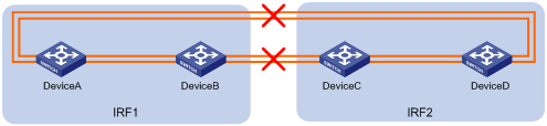
# Observe the output messages to verify that LACP MAD takes the following actions:
· Changes IRF 2 (Device C and Device D) to the Recovery state, because the master device in IRF 1 has a lower member ID than the master device in IRF 2.
· Shuts down all service interfaces on Device C and Device D, except for the IRF physical interfaces and the service interfaces excluded from the MAD shutdown action.
The following is the sample output on IRF 1:
%Jan 1 05:19:10:176 2019 H3C STM/3/STM_LINK_STATUS_DOWN: IRF port 2 is down.
%Jan 1 05:19:10:184 2019 H3C IFNET/3/PHY_UPDOWN: HundredGigE1/0/27 link status is down.
%Jan 1 05:19:10:184 2019 H3C IFNET/3/PHY_UPDOWN: HundredGigE1/0/28 link status is down.
%Jan 1 05:19:10:176 2019 H3C STM/3/STM_LINK_STATUS_DOWN: IRF port 1 is down.
%Jan 1 05:19:10:184 2019 H3C IFNET/3/PHY_UPDOWN: HundredGigE2/0/25 link status is down.
%Jan 1 05:19:10:184 2019 H3C IFNET/3/PHY_UPDOWN: HundredGigE2/0/26 link status is down.
%Jan 1 05:19:10:186 2019 H3C DEV/3/BOARD_REMOVED: Board is removed from Slot 3, type is MAIN_BOARD_TYPE_54QT.
%Jan 1 05:19:10:186 2019 H3C DEV/3/BOARD_REMOVED: Board is removed from Slot 4, type is MAIN_BOARD_TYPE_54QT.
The following is the sample output from IRF 2:
%Jan 1 05:53:20:784 2019 H3C HA/5/HA_STANDBY_TO_MASTER: Standby board in slot 3 changes to master.
%Jan 1 05:53:20:831 2019 H3C DEV/3/BOARD_REMOVED: Board is removed from Slot 1, type is MAIN_BOARD_TYPE_56HF.
%Jan 1 05:53:20:831 2019 H3C DEV/3/BOARD_REMOVED: Board is removed from Slot 2, type is MAIN_BOARD_TYPE_56HF.
%Jan 1 05:53:20:860 2019 H3C DEV/1/MAD_DETECT: Multi-active devices detected, please fix it.
%Jan 1 05:53:20:886 2019 H3C IFNET/3/PHY_UPDOWN: M-GigabitEthernet0/0/0 link status is down.
%Jan 1 05:53:20:887 2019 H3C IFNET/5/LINK_UPDOWN: Line protocol on the interface M-GigabitEthernet0/0/0 is down.
%Jan 1 05:53:20:912 2019 H3C IFNET/3/PHY_UPDOWN: HundredGigE3/0/29 link status is down.
%Jan 1 05:53:20:914 2019 H3C IFNET/5/LINK_UPDOWN: Line protocol on the interface HundredGigE3/0/29 is down.
%Jan 1 05:53:20:912 2019 H3C IFNET/3/PHY_UPDOWN: HundredGigE3/0/30 link status is down.
%Jan 1 05:53:20:914 2019 H3C IFNET/5/LINK_UPDOWN: Line protocol on the interface HundredGigE3/0/30 is down.
%Jan 1 05:53:20:912 2019 H3C IFNET/3/PHY_UPDOWN: HundredGigE4/0/29 link status is down.
%Jan 1 05:53:20:914 2019 H3C IFNET/5/LINK_UPDOWN: Line protocol on the interface HundredGigE4/0/29 is down.
%Jan 1 05:53:20:912 2019 H3C IFNET/3/PHY_UPDOWN: HundredGigE4/0/30 link status is down.
%Jan 1 05:53:20:914 2019 H3C IFNET/5/LINK_UPDOWN: Line protocol on the interface HundredGigE4/0/30 is down.
The output shows that initially IRF 2 took over the master role because it falsely identified that IRF 1 has failed. LACP MAD shut down the service interfaces on IRF 2 after it detected an MAD conflict.
# If IRF 1 fails, use the mad restore command on IRF 2 to recover the member devices and bring up all service interfaces that have been shut down by LACP MAD.
|
|
NOTE: You can log in to IRF 2 through the console port on Device C or Device D. If you have excluded a service interface from the MAD shutdown action, you can Telnet to IRF 2 through the service interface. |
<Sysname> system-view
[Sysname] mad restore
This command will restore the device from multi-active conflict state. Continue? [Y/N]:y
Restoring from multi-active conflict state, please wait...
[Sysname]
%Jan 1 05:24:41:249 2019 H3C IFNET/3/PHY_UPDOWN: Twenty-FiveGigE2/0/10 link status is up.
%Jan 1 05:24:41:249 2019 H3C IFNET/5/LINK_UPDOWN: Line protocol on the interface Twenty-FiveGigE2/0/10 is up.
%Jan 1 05:24:41:325 2019 H3C IFNET/3/PHY_UPDOWN: HundredGigE2/0/29 link status is up.
%Jan 1 05:24:41:325 2019 H3C IFNET/3/PHY_UPDOWN: HundredGigE2/0/30 link status is up.
%Jan 1 05:24:46:266 2019 H3C IFNET/3/PHY_UPDOWN: M-GigabitEthernet0/0/0 link status is up.
%Jan 1 05:24:46:268 2019 H3C IFNET/5/LINK_UPDOWN: Line protocol on the interface M-GigabitEthernet0/0/0 is up.
The output shows that network connectivity of IRF 2 has been restored.
# Remove all IRF 1 and IRF link failures.
# After the link failure of IRF 1 is removed, the IRF ports recover. The following is the sample output on IRF 1:
%Jan 1 05:29:06:913 2019 H3C IFNET/3/PHY_UPDOWN: HundredGigE1/0/27 link status is up.
%Jan 1 05:29:06:914 2019 H3C IFNET/5/LINK_UPDOWN: Line protocol on the interface HundredGigE1/0/27 is up.
%Jan 1 05:29:06:913 2019 H3C IFNET/3/PHY_UPDOWN: HundredGigE1/0/28 link status is up.
%Jan 1 05:29:06:914 2019 H3C IFNET/5/LINK_UPDOWN: Line protocol on the interface HundredGigE1/0/28 is up.
%Jan 1 05:29:07:106 2019 H3C STM/6/STM_LINK_STATUS_UP: IRF port 2 is up.
%Jan 1 05:29:07:810 2019 H3C STM/4/STM_LINK_RECOVERY: Merge occurs.
IRF 2 reboots automatically to merge with IRF 1.
# Verify that the IRF fabric is recovered with Device A as the master.
<IRF> display irf
MemberID Role Priority CPU-Mac Description
*+1 Master 31 00e0-fc0f-8c02 ---
2 Standby 1 00e0-fc0f-8c03 ---
3 Standby 1 00e0-fc0f-8c04 ---
4 Standby 1 00e0-fc0f-8c05 ---
--------------------------------------------------
* indicates the device is the master.
+ indicates the device through which the user logs in.
The Bridge MAC of the IRF is: 0cda-414a-859b
Auto upgrade : yes
Mac persistent : 12 min
Domain ID : 1
Configuration files
· IRF fabric at the access layer:
#
sysname IRF
#
irf domain 1
irf member 1 priority 31
#
vlan 10
#
irf-port1/1
port group interface HundredGigE1/0/25
port group interface HundredGigE1/0/26
#
irf-port1/2
port group interface HundredGigE1/0/27
port group interface HundredGigE1/0/28
#
irf-port2/1
port group interface HundredGigE2/0/25
port group interface HundredGigE2/0/26
#
irf-port2/2
port group interface HundredGigE2/0/27
port group interface HundredGigE2/0/28
#
irf-port3/1
port group interface HundredGigE3/0/25
port group interface HundredGigE3/0/26
#
irf-port3/2
port group interface HundredGigE3/0/27
port group interface HundredGigE3/0/28
#
irf-port4/1
port group interface HundredGigE4/0/25
port group interface HundredGigE4/0/26
#
irf-port4/2
port group interface HundredGigE4/0/27
port group interface HundredGigE4/0/28
#
interface Bridge-Aggregation2
port link-type trunk
port trunk permit vlan 1 10
link-aggregation mode dynamic
mad enable
#
interface Bridge-Aggregation3
port access vlan 10
link-aggregation mode dynamic
#
interface HundredGigE1/0/29
port link-mode bridge
port link-type trunk
port trunk permit vlan 1 10
port link-aggregation group 2
#
interface HundredGigE1/0/30
port link-mode bridge
port link-type trunk
port trunk permit vlan 1 10
port link-aggregation group 2
#
interface HundredGigE2/0/29
port link-mode bridge
port link-type trunk
port trunk permit vlan 1 10
port link-aggregation group 2
#
interface HundredGigE2/0/30
port link-mode bridge
port link-type trunk
port trunk permit vlan 1 10
port link-aggregation group 2
#
interface HundredGigE3/0/29
port link-mode bridge
port link-type trunk
port trunk permit vlan 1 10
port link-aggregation group 2
#
interface HundredGigE3/0/30
port link-mode bridge
port link-type trunk
port trunk permit vlan 1 10
port link-aggregation group 2
#
interface HundredGigE4/0/29
port link-mode bridge
port link-type trunk
port trunk permit vlan 1 10
port link-aggregation group 2
#
interface HundredGigE4/0/30
port link-mode bridge
port link-type trunk
port trunk permit vlan 1 10
port link-aggregation group 2
#
interface Twenty-FiveGigE1/0/10
port link-mode bridge
port access vlan 10
port link-aggregation group 3
#
interface Twenty-FiveGigE2/0/10
port link-mode bridge
port access vlan 10
port link-aggregation group 3
· IRF fabric at the distribution layer:
#
irf domain 2
#
vlan10
#
interface Bridge-Aggregation2
port link-type trunk
port trunk permit vlan 1 10
link-aggregation mode dynamic
mad enable
#
interface HundredGigE1/2/0/1
port link-mode bridge
port link-type trunk
port trunk permit vlan 1 10
port link-aggregation group 2
#
interface HundredGigE1/3/0/1
port link-mode bridge
port link-type trunk
port trunk permit vlan 1 10
port link-aggregation group 2
#
interface HundredGigE2/2/0/1
port link-mode bridge
port link-type trunk
port trunk permit vlan 1 10
port link-aggregation group 2
#
interface HundredGigE2/3/0/1
port link-mode bridge
port link-type trunk
port trunk permit vlan 1 10
port link-aggregation group 2
#
interface HundredGigE3/2/0/1
port link-mode bridge
port link-type trunk
port trunk permit vlan 1 10
port link-aggregation group 2
#
interface HundredGigE3/3/0/1
port link-mode bridge
port link-type trunk
port trunk permit vlan 1 10
port link-aggregation group 2
#
interface HundredGigE4/2/0/1
port link-mode bridge
port link-type trunk
port trunk permit vlan 1 10
port link-aggregation group 2
#
interface HundredGigE4/3/0/1
port link-mode bridge
port link-type trunk
port trunk permit vlan 1 10
port link-aggregation group 2
Example: Setting up a four-chassis BFD MAD-enabled IRF fabric
Network configuration
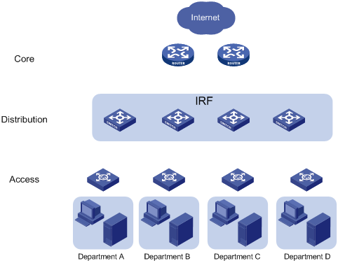
As shown in Figure 8, set up a four-chassis IRF fabric to replace the switches at the distribution layer of the enterprise network (see Figure 7).
Use BFD MAD to detect IRF split.
The IRF fabric provides gateway services for servers and runs OSPF.
Figure 7 Network diagram before IRF deployment
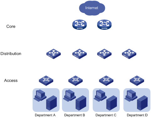
Figure 8 Network diagram after IRF deployment
Analysis
The requirements in this example include the following categories:
· Network connectivity configuration
IRF setup
To set up an IRF fabric, determine the items in Table 4.
|
Item |
Analysis |
Choice in this example |
|
Topology |
You can use a ring or daisy-chain topology for a three- or four-chassis IRF fabric. For reliability, use the ring topology. |
Ring topology (see Figure 9). |
|
Member ID assignment |
IRF member IDs must be unique. |
Device A—1. Device B—2. Device C—3. Device D—4. |
|
Master device |
IRF members elect a master automatically. For a member device to be elected the master, assign it the highest member priority. |
Device A. |
|
IRF port bindings |
Make sure the IRF port bindings are consistent with the physical connections. For high availability, bind multiple physical interfaces to an IRF port. These ports will automatically aggregate for load balancing and redundancy. |
See Table 5. |
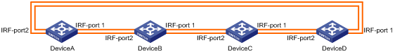
Table 5 IRF physical interface bindings
|
IRF port |
IRF physical interfaces |
|
Device A: |
|
|
IRF-port 1 |
HundredGigE 1/0/25 HundredGigE 1/0/26 |
|
IRF-port 2 |
HundredGigE 1/0/27 HundredGigE 1/0/28 |
|
Device B: |
|
|
IRF-port 1 |
HundredGigE 2/0/25 HundredGigE 2/0/26 |
|
IRF-port 2 |
HundredGigE 2/0/27 HundredGigE 2/0/28 |
|
Device C: |
|
|
IRF-port 1 |
HundredGigE 3/0/25 HundredGigE 3/0/26 |
|
IRF-port 2 |
HundredGigE 3/0/27 HundredGigE 3/0/28 |
|
Device D: |
|
|
IRF-port 1 |
HundredGigE 4/0/25 HundredGigE 4/0/26 |
|
IRF-port 2 |
HundredGigE 4/0/27 HundredGigE 4/0/28 |
|
|
NOTE: The first segment in a physical interface number is the IRF member ID. By default, the IRF member ID is 1. Table 5 shows the interface numbers after the member IDs are changed. |
BFD MAD configuration
You can deploy BFD MAD by using one of the following methods:
· Connect all member devices with dedicated BFD MAD links into a full mesh topology. This method is suitable for two-chassis IRF fabrics.
· Set up a dedicated BFD MAD link with an intermediate device for each IRF member device, as shown in Figure 10. This method is suitable for IRF fabrics that have more than two member devices, because it uses fewer physical interfaces than the previous method.
The intermediate device forwards BFD MAD packets transparently. You do not need to configure any special settings on the intermediate device except that you must assign all BFD MAD links to the VLAN used for BFD MAD.
Figure 10 BFD MAD connection diagram
Network connectivity configuration
IRF is typically used with link aggregation to simplify the network topology. For high availability, set up multichassis link aggregations with the downstream switches and the upstream egress routers, as shown in Figure 11. The figure uses a single device to represents the four-chassis IRF fabric.
A link aggregation could span one member device, some of the member devices, or all member devices, depending on the link redundancy requirements and number of available links. Because this example does not use LACP MAD, the link aggregation mode can be dynamic or static. This example uses dynamic aggregation mode for all link aggregations.
To use the IRF fabric as the gateway for servers, you must configure VLAN interfaces to provide gateway services, as shown in Table 6.
To use the IRF fabric in a Layer 3 network, you must configure routing. In this example, OSPF is configured.
Figure 11 Connection diagram for the IRF fabric in a Layer 3 network
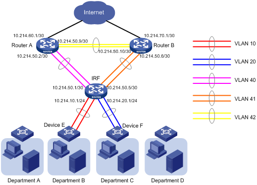
Table 6 Link aggregations and VLAN assignment scheme
|
Aggregate interface |
Member ports |
VLANs |
VLAN interface's IP address |
|
Router A: |
|
|
|
|
Bridge-Aggregation 40 |
Twenty-FiveGigE 1/0/1 Twenty-FiveGigE 1/0/2 Twenty-FiveGigE 1/0/3 Twenty-FiveGigE 1/0/4 |
VLAN 40 |
10.214.50.2/30 |
|
Bridge-Aggregation 42 |
Twenty-FiveGigE 1/0/5 Twenty-FiveGigE 1/0/6 |
VLAN 42 |
10.214.50.9/30 |
|
Router B: |
|
|
|
|
Bridge-Aggregation 41 |
Twenty-FiveGigE 1/0/1 Twenty-FiveGigE 1/0/2 Twenty-FiveGigE 1/0/3 Twenty-FiveGigE 1/0/4 |
VLAN 41 |
10.214.50.6/30 |
|
Bridge-Aggregation 42 |
Twenty-FiveGigE 1/0/5 Twenty-FiveGigE 1/0/6 |
VLAN 42 |
10.214.50.10/30 |
|
IRF fabric: |
|
|
|
|
Bridge-Aggregation 10 |
Twenty-FiveGigE 1/0/10 Twenty-FiveGigE 2/0/10 Twenty-FiveGigE 3/0/10 Twenty-FiveGigE 4/0/10 |
VLAN 10 |
10.214.10.1/24 |
|
Bridge-Aggregation 20 |
Twenty-FiveGigE 1/0/11 Twenty-FiveGigE 2/0/11 Twenty-FiveGigE 3/0/11 Twenty-FiveGigE 4/0/11 |
VLAN 20 |
10.214.20.1/24 |
|
Bridge-Aggregation 40 |
Twenty-FiveGigE 1/0/13 Twenty-FiveGigE 2/0/13 Twenty-FiveGigE 3/0/13 Twenty-FiveGigE 4/0/13 |
VLAN 40 |
10.214.50.1/30 |
|
Bridge-Aggregation 41 |
Twenty-FiveGigE 1/0/14 Twenty-FiveGigE 2/0/14 Twenty-FiveGigE 3/0/14 Twenty-FiveGigE 4/0/14 |
VLAN 41 |
10.214.50.5/30 |
|
Device E: |
|
|
|
|
Bridge-Aggregation 10 |
Twenty-FiveGigE 1/0/49 Twenty-FiveGigE 1/0/50 Twenty-FiveGigE 1/0/51 Twenty-FiveGigE 1/0/52 |
VLAN 10 |
No VLAN interface is required. |
|
Device F: |
|
|
|
|
Bridge-Aggregation 20 |
Twenty-FiveGigE 1/0/49 Twenty-FiveGigE 1/0/50 Twenty-FiveGigE 1/0/51 Twenty-FiveGigE 1/0/52 |
VLAN 20 |
No VLAN interface is required. |
Applicable hardware and software versions
The following matrix shows the hardware and software versions to which this configuration example is applicable:
|
Hardware |
Software version |
|
S6850 switch series S9850 switch series |
Release 6555P01 |
|
S9820-64H switch |
Release 6555P01 |
Restrictions and guidelines
When you configure BFD MAD on a VLAN interface, follow these restrictions and guidelines:
|
Category |
Restrictions and guidelines |
|
BFD MAD VLAN |
· Do not enable BFD MAD on VLAN-interface 1. · If you are using an intermediate device, perform the following tasks on both the IRF fabric and the intermediate device: ¡ Create a VLAN and VLAN interface for BFD MAD. ¡ Assign the ports of BFD MAD links to the BFD MAD VLAN. · Make sure the IRF fabrics on the network use different BFD MAD VLANs. · Make sure the BFD MAD VLAN contains only ports on the BFD MAD links. Exclude a port from the BFD MAD VLAN if the port is not on the BFD MAD link. For example, if you have assigned the port to all VLANs by using the port trunk permit vlan all command, use the undo port trunk permit command to exclude the port from the BFD MAD VLAN. |
|
BFD MAD VLAN and feature compatibility |
Do not use the BFD MAD VLAN for any purposes other than configuring BFD MAD. · On the IRF fabric, configure only the mad bfd enable and mad ip address commands on the VLAN interface used for BFD MAD. On the intermediate device (if any) and IRF fabric, do not configure any other features on the ports used for BFD MAD. If you configure other features, both BFD MAD and other features on the interface or ports might run incorrectly. · Disable the spanning tree feature on all Layer 2 Ethernet ports in the BFD MAD VLAN. The MAD feature is mutually exclusive with the spanning tree feature. |
|
MAD IP address |
· Use the mad ip address command instead of the ip address command to configure MAD IP addresses on the BFD MAD-enabled interface. · Make sure all the MAD IP addresses are on the same subnet and not used by any member device. |
Procedures
Setting up the IRF fabric
1. Configure Device A:
# Shut down the physical interfaces used for IRF connection. This example uses HundredGigE 1/0/25 to HundredGigE 1/0/28 for IRF connection.
<DeviceA> system-view
[DeviceA] interface range hundredgige 1/0/25 to hundredgige 1/0/28
[DeviceA-if-range] shutdown
[DeviceA-if-range] quit
# Bind HundredGigE 1/0/25 and HundredGigE 1/0/26 to IRF-port 1/1.
[DeviceA] irf-port 1/1
[DeviceA-irf-port1/1] port group interface hundredgige 1/0/25
[DeviceA-irf-port1/1] port group interface hundredgige 1/0/26
[DeviceA-irf-port1/1] quit
# Bind HundredGigE 1/0/27 and HundredGigE 1/0/28 to IRF-port 1/2.
[DeviceA] irf-port 1/2
[DeviceA-irf-port1/2] port group interface hundredgige 1/0/27
[DeviceA-irf-port1/2] port group interface hundredgige 1/0/28
[DeviceA-irf-port1/2] quit
# Bring up the physical interfaces.
[DeviceA] interface range hundredgige 1/0/25 to hundredgige 1/0/28
[DeviceA-if-range] undo shutdown
[DeviceA-if-range] quit
# Assign IRF member priority 31 to Device A. This priority is high enough to ensure that Device A can be elected as the master.
[DeviceA] irf member 1 priority 31
# Save the running configuration.
[DeviceA] quit
<DeviceA> save
# Activate the IRF port configuration.
<DeviceA> system-view
[DeviceA] irf-port-configuration active
2. Configure Device B:
# Assign member ID 2 to Device B, and reboot the device to have the change take effect.
<DeviceB> system-view
[DeviceB] irf member 1 renumber 2
Renumbering the member ID may result in configuration change or loss. Continue? [Y/N]:y
[DeviceB] quit
<DeviceB> reboot
# Shut down the physical interfaces used for IRF connection. This example uses HundredGigE 2/0/25 to HundredGigE 2/0/28 for IRF connection.
<DeviceB> system-view
[DeviceB] interface range hundredgige 2/0/25 to hundredgige 2/0/28
[DeviceB-if-range] shutdown
[DeviceB-if-range] quit
# Bind HundredGigE 2/0/25 and HundredGigE 2/0/26 to IRF-port 2/1.
[DeviceB] irf-port 2/1
[DeviceB-irf-port2/1] port group interface hundredgige 2/0/25
[DeviceB-irf-port2/1] port group interface hundredgige 2/0/26
[DeviceB-irf-port2/1] quit
# Bind HundredGigE 2/0/27 and HundredGigE 2/0/28 to IRF-port 2/2.
[DeviceB] irf-port 2/2
[DeviceB-irf-port2/2] port group interface hundredgige 2/0/27
[DeviceB-irf-port2/2] port group interface hundredgige 2/0/28
[DeviceB-irf-port2/2] quit
# Bring up the physical interfaces.
[DeviceB] interface range hundredgige 2/0/25 to hundredgige 2/0/28
[DeviceB-if-range] undo shutdown
[DeviceB-if-range] quit
# Save the running configuration.
[DeviceB] quit
<DeviceB> save
# Connect Device B to Device A, as shown in Figure 9.
# Activate the IRF port configuration.
<DeviceB> system-view
[DeviceB] irf-port-configuration active
Device B has a lower priority than Device A, and Device B fails master election and reboots. A two-chassis IRF fabric is formed.
3. Configure Device C:
# Assign member ID 3 to Device C, and reboot the device to have the change take effect.
<DeviceC> system-view
[DeviceC] irf member 1 renumber 3
Renumbering the member ID may result in configuration change or loss. Continue? [Y/N]:y
[DeviceC] quit
<DeviceC> reboot
# Shut down the physical interfaces used for IRF connection. This example uses HundredGigE 3/0/25 to HundredGigE 3/0/28 for IRF connection.
<DeviceC> system-view
[DeviceC] interface range hundredgige 3/0/25 to hundredgige 3/0/28
[DeviceC-if-range] shutdown
[DeviceC-if-range] quit
# Bind HundredGigE 3/0/25 and HundredGigE 3/0/26 to IRF-port 3/1.
[DeviceC] irf-port 3/1
[DeviceC-irf-port3/1] port group interface hundredgige 3/0/25
[DeviceC-irf-port3/1] port group interface hundredgige 3/0/26
[DeviceC-irf-port3/1] quit
# Bind HundredGigE 3/0/27 and HundredGigE 3/0/28 to IRF-port 3/2.
[DeviceC] irf-port 3/2
[DeviceC-irf-port3/2] port group interface hundredgige 3/0/27
[DeviceC-irf-port3/2] port group interface hundredgige 3/0/28
[DeviceC-irf-port3/2] quit
# Bring up the physical interfaces.
[DeviceC] interface range hundredgige 3/0/25 to hundredgige 3/0/28
[DeviceC-if-range] undo shutdown
[DeviceC-if-range] quit
# Save the running configuration.
[DeviceC] quit
<DeviceC> save
# Connect Device C to Device B, as shown in Figure 9.
# Activate the IRF port configuration.
<DeviceC> system-view
[DeviceC] irf-port-configuration active.
Device C reboots to join the IRF fabric. A three-chassis IRF fabric is formed.
4. Configure Device D:
# Assign member ID 4 to Device D, and reboot the device to have the change take effect.
<DeviceD> system-view
[DeviceD] irf member 1 renumber 4
Renumbering the member ID may result in configuration change or loss. Continue? [Y/N]:y
[DeviceD] quit
<DeviceD> reboot
# Shut down the physical interfaces used for IRF connection. This example uses HundredGigE 4/0/25 to HundredGigE 4/0/28 for IRF connection.
<DeviceD> system-view
[DeviceD] interface range hundredgige 4/0/25 to hundredgige 4/0/28
[DeviceD-if-range] shutdown
[DeviceD-if-range] quit
# Bind HundredGigE 4/0/25 and HundredGigE 4/0/26 to IRF-port 4/1.
[DeviceD] irf-port 4/1
[DeviceD-irf-port4/1] port group interface hundredgige 4/0/25
[DeviceD-irf-port4/1] port group interface hundredgige 4/0/26
[DeviceD-irf-port4/1] quit
# Bind HundredGigE 4/0/27 and HundredGigE 4/0/28 to IRF-port 4/2.
[DeviceD] irf-port 4/2
[DeviceD-irf-port4/2] port group interface hundredgige 4/0/27
[DeviceD-irf-port4/2] port group interface hundredgige 4/0/28
[DeviceD-irf-port4/2] quit
# Bring up the physical interfaces.
[DeviceD] interface range hundredgige 4/0/25 to hundredgige 4/0/28
[DeviceD-if-range] undo shutdown
[DeviceD-if-range] quit
# Save the running configuration.
[DeviceD] quit
<DeviceD> save
# Connect Device D to Device C and Device A, as shown in Figure 9.
# Activate the IRF port configuration.
<DeviceD> system-view
[DeviceD] irf-port-configuration active
Device D reboots to join the IRF fabric. A four-chassis IRF fabric is formed. The command prompt changes to the name of Device A.
# Change the name of the IRF fabric.
<DeviceA> system-view
[DeviceA] sysname IRF
[IRF]
Configuring BFD MAD
1. Configure the IRF fabric:
# Create VLAN 1000 (BFD MAD VLAN).
<IRF> system-view
[IRF] vlan 1000
# Add all ports used for BFD MAD to the VLAN, including Twenty-FiveGigE 1/0/1, Twenty-FiveGigE 2/0/1, Twenty-FiveGigE 3/0/1, and Twenty-FiveGigE 4/0/1.
[IRF-vlan1000] port twenty-fivegige 1/0/1 twenty-fivegige 2/0/1 twenty-fivegige 3/0/1 twenty-fivegige 4/0/1
[IRF-vlan3] quit
# Create VLAN-interface 1000, and configure a MAD IP address for each member device on the interface.
[IRF] interface vlan-interface 1000
[IRF-Vlan-interface1000] mad bfd enable
[IRF-Vlan-interface1000] mad ip address 192.168.2.1 24 member 1
[IRF-Vlan-interface1000] mad ip address 192.168.2.2 24 member 2
[IRF-Vlan-interface1000] mad ip address 192.168.2.3 24 member 3
[IRF-Vlan-interface1000] mad ip address 192.168.2.4 24 member 4
[IRF-Vlan-interface1000] quit
# Disable the spanning tree feature on the ports in the BFD MAD VLAN.
[IRF] interface twenty-fivegige 1/0/1
[IRF-Twenty-FiveGigE1/0/1] undo stp enable
[IRF-Twenty-FiveGigE1/0/1] quit
[IRF] interface twenty-fivegige 2/0/1
[IRF-Twenty-FiveGigE2/0/1] undo stp enable
[IRF-Twenty-FiveGigE2/0/1] quit
[IRF] interface twenty-fivegige 3/0/1
[IRF-Twenty-FiveGigE3/0/1] undo stp enable
[IRF-Twenty-FiveGigE3/0/1] quit
[IRF] interface twenty-fivegige 4/0/1
[IRF-Twenty-FiveGigE4/0/1] undo stp enable
[IRF-Twenty-FiveGigE4/0/1] quit
2. Configure the intermediate device:
# Create VLAN 1000 (BFD MAD VLAN).
<Sysname> system-view
[Sysname] vlan 1000
# Add all ports used for BFD MAD to the VLAN, including Twenty-FiveGigE 1/0/1, Twenty-FiveGigE 1/0/2, Twenty-FiveGigE 1/0/3, and Twenty-FiveGigE 1/0/4.
[Sysname-vlan1000] port twenty-fivegige 1/0/1 twenty-fivegige 1/0/2 twenty-fivegige 1/0/3 twenty-fivegige 1/0/4
[Sysname-vlan3] quit
Configuring network connectivity settings
This example only contains network connectivity configuration for Department B and Department C. The core router configuration does not include the connection to the public network.
1. Configure Router A:
# Create VLANs 40 and 42.
<RouterA> system-view
[RouterA] vlan 40
[RouterA-vlan40] quit
[RouterA] vlan 42
[RouterA-vlan42] quit
# Create Bridge-Aggregation 40, and set its link aggregation mode to dynamic.
[RouterA] interface bridge-aggregation 40
[RouterA-Bridge-Aggregation40] link-aggregation mode dynamic
[RouterA-Bridge-Aggregation40] quit
# Assign Twenty-FiveGigE 1/0/1, Twenty-FiveGigE 1/0/2, Twenty-FiveGigE 1/0/3, and Twenty-FiveGigE 1/0/4 to the aggregation group for Bridge-Aggregation 40.
[RouterA] interface twenty-fivegige 1/0/1
[RouterA-Twenty-FiveGigE1/0/1] port link-aggregation group 40
[RouterA-Twenty-FiveGigE1/0/1] quit
[RouterA] interface twenty-fivegige 1/0/2
[RouterA-Twenty-FiveGigE1/0/2] port link-aggregation group 40
[RouterA-Twenty-FiveGigE1/0/2] quit
[RouterA] interface twenty-fivegige 1/0/3
[RouterA-Twenty-FiveGigE1/0/3] port link-aggregation group 40
[RouterA-Twenty-FiveGigE1/0/3] quit
[RouterA] interface twenty-fivegige 1/0/4
[RouterA-Twenty-FiveGigE1/0/4] port link-aggregation group 40
[RouterA-Twenty-FiveGigE1/0/4] quit
# Assign Bridge-Aggregation 40 to VLAN 40.
[RouterA] interface bridge-aggregation 40
[RouterA-Bridge-Aggregation40] port access vlan 40
# Create Bridge-Aggregation 42, and set its link aggregation mode to dynamic.
[RouterA] interface bridge-aggregation 42
[RouterA-Bridge-Aggregation42] link-aggregation mode dynamic
[RouterA-Bridge-Aggregation42] quit
# Assign Twenty-FiveGigE 1/0/5 and Twenty-FiveGigE 1/0/6 to the aggregation group for Bridge-Aggregation 42.
[RouterA] interface twenty-fivegige 1/0/5
[RouterA-Twenty-FiveGigE1/0/5] port link-aggregation group 42
[RouterA-Twenty-FiveGigE1/0/5] quit
[RouterA] interface twenty-fivegige 1/0/6
[RouterA-Twenty-FiveGigE1/0/6] port link-aggregation group 42
[RouterA-Twenty-FiveGigE1/0/6] quit
# Assign Bridge-Aggregation 42 to VLAN 42.
[RouterA] interface bridge-aggregation 42
[RouterA-Bridge-Aggregation42] port access vlan 42
[RouterA-Bridge-Aggregation42] quit
# Create VLAN-interface 40 and VLAN-interface 42, and assign IP addresses to the VLAN interfaces.
[RouterA] interface vlan-interface 40
[RouterA-Vlan-interface40] ip address 10.214.50.2 30
[RouterA-Vlan-interface40] quit
[RouterA] interface vlan-interface 42
[RouterA-Vlan-interface42] ip address 10.214.50.9 30
[RouterA-Vlan-interface42] quit
# Configure OSPF.
[RouterA] ospf
[RouterA-ospf-1] import-route direct
[RouterA-ospf-1] area 0
[RouterA-ospf-1-area-0.0.0.0] network 10.214.60.0 0.0.0.3
[RouterA-ospf-1-area-0.0.0.0] network 10.214.50.0 0.0.0.3
[RouterA-ospf-1-area-0.0.0.0] network 10.214.50.8 0.0.0.3
[RouterA-ospf-1-area-0.0.0.0] quit
[RouterA-ospf-1] quit
2. Configure Router B:
# Create VLANs 41 and 42.
<RouterB> system-view
[RouterB] vlan 41 to 42
# Create Bridge-Aggregation 41, and set its link aggregation mode to dynamic.
[RouterB] interface bridge-aggregation 41
[RouterB-Bridge-Aggregation41] link-aggregation mode dynamic
[RouterB-Bridge-Aggregation41] quit
# Assign Twenty-FiveGigE 1/0/1, Twenty-FiveGigE 1/0/2, Twenty-FiveGigE1/0/3, and Twenty-FiveGigE 1/0/4 to the aggregation group for Bridge-Aggregation 41.
[RouterB] interface twenty-fivegige 1/0/1
[RouterB-Twenty-FiveGigE1/0/1] port link-aggregation group 41
[RouterB-Twenty-FiveGigE1/0/1] quit
[RouterB] interface twenty-fivegige 1/0/2
[RouterB-Twenty-FiveGigE1/0/2] port link-aggregation group 41
[RouterB-Twenty-FiveGigE1/0/2] quit
[RouterB] interface twenty-fivegige 1/0/3
[RouterB-Twenty-FiveGigE1/0/3] port link-aggregation group 41
[RouterB-Twenty-FiveGigE1/0/3] quit
[RouterB] interface twenty-fivegige 1/0/4
[RouterB-Twenty-FiveGigE1/0/4] port link-aggregation group 41
[RouterB-Twenty-FiveGigE1/0/4] quit
# Assign Bridge-Aggregation 41 to VLAN 41.
[RouterB] interface bridge-aggregation 41
[RouterB-Bridge-Aggregation41] port access vlan 41
[RouterB-Bridge-Aggregation41] quit
# Create Bridge-Aggregation 42, and set its link aggregation mode to dynamic.
[RouterB] interface bridge-aggregation 42
[RouterB-Bridge-Aggregation42] link-aggregation mode dynamic
[RouterB-Bridge-Aggregation42] port access vlan 42
[RouterB-Bridge-Aggregation42] quit
# Assign Twenty-FiveGigE 1/0/5 and Twenty-FiveGigE 1/0/6 to the aggregation group for Bridge-Aggregation 42.
[RouterB] interface twenty-fivegige 1/0/5
[RouterB-Twenty-FiveGigE1/0/5] port link-aggregation group 42
[RouterB-Twenty-FiveGigE1/0/5] quit
[RouterB] interface twenty-fivegige 1/0/6
[RouterB-Twenty-FiveGigE1/0/6] port link-aggregation group 42
[RouterB-Twenty-FiveGigE1/0/6] quit
# Assign Bridge-Aggregation 42 to VLAN 42.
[RouterB] interface bridge-aggregation 42
[RouterB-Bridge-Aggregation42] port access vlan 42
[RouterB-Bridge-Aggregation42] quit
# Create VLAN-interface 41 and VLAN-interface 42, and assign IP addresses to the VLAN interfaces.
[RouterB] interface vlan-interface 41
[RouterB-Vlan-interface41] ip address 10.214.50.6 30
[RouterB-Vlan-interface41] quit
[RouterB] interface vlan-interface 42
[RouterB-Vlan-interface42] ip address 10.214.50.10 30
[RouterB-Vlan-interface42] quit
# Configure OSPF.
[RouterB] ospf
[RouterB-ospf-1] import-route direct
[RouterB-ospf-1] area 0
[RouterB-ospf-1-area-0.0.0.0] network 10.214.70.0 0.0.0.3
[RouterB-ospf-1-area-0.0.0.0] network 10.214.50.0 0.0.0.3
[RouterB-ospf-1-area-0.0.0.0] network 10.214.50.8 0.0.0.3
[RouterB-ospf-1-area-0.0.0.0] quit
[RouterB-ospf-1] quit
3. Configure the IRF fabric:
# Create VLANs 10, 20, 40, and 41.
<IRF> system-view
[IRF] vlan 10
[IRF-vlan10] quit
[IRF] vlan 20
[IRF-vlan20] quit
[IRF] vlan 40
[IRF-vlan40] quit
[IRF] vlan 41
[IRF-vlan41] quit
# Create Bridge-Aggregation 10, and set its link aggregation mode to dynamic.
[IRF] interface bridge-aggregation 10
[IRF-Bridge-Aggregation10] link-aggregation mode dynamic
[IRF-Bridge-Aggregation10] quit
# Assign Twenty-FiveGigE 1/0/10, Twenty-FiveGigE 2/0/10, Twenty-FiveGigE 3/0/10, and Twenty-FiveGigE 4/0/10 to the aggregation group for Bridge-Aggregation 10.
[IRF] interface twenty-fivegige 1/0/10
[IRF-Twenty-FiveGigE1/0/10] port link-aggregation group 10
[IRF-Twenty-FiveGigE1/0/10] quit
[IRF] interface twenty-fivegige 2/0/10
[IRF-Twenty-FiveGigE2/0/10] port link-aggregation group 10
[IRF-Twenty-FiveGigE2/0/10] quit
[IRF] interface twenty-fivegige 3/0/10
[IRF-Twenty-FiveGigE3/0/10] port link-aggregation group 10
[IRF-Twenty-FiveGigE3/0/10] quit
[IRF] interface twenty-fivegige 4/0/10
[IRF-Twenty-FiveGigE4/0/10] port link-aggregation group 10
[IRF-Twenty-FiveGigE4/0/10] quit
# Assign Bridge-Aggregation 10 to VLAN 10.
[IRF] interface bridge-aggregation 10
[IRF-Bridge-Aggregation10] port access vlan 10
[IRF-Bridge-Aggregation10] quit
# Repeat the previous Bridge-Aggregation 10 configuration steps to configure Bridge-Aggregation interfaces 20, 40, and 41, in compliance with the scheme in Table 6. (Details not shown.)
# Create interfaces for VLANs 10, 20, 40, and 41, and assign IP addresses to the interfaces.
[IRF] interface vlan-interface 10
[IRF-Vlan-interface10] ip address 10.214.10.1 24
[IRF-Vlan-interface10] quit
[IRF] interface vlan-interface 20
[IRF-Vlan-interface20] ip address 10.214.20.1 24
[IRF-Vlan-interface20] quit
[IRF] interface vlan-interface 40
[IRF-Vlan-interface40] ip address 10.214.50.1 30
[IRF-Vlan-interface40] quit
[IRF] interface vlan-interface 41
[IRF-Vlan-interface41] ip address 10.214.50.5 30
[IRF-Vlan-interface41] quit
# Configure OSPF.
[IRF] ospf
[IRF-ospf-1] import-route direct
[IRF-ospf-1] area 0
[IRF-ospf-1-area-0.0.0.0] network 10.214.10.0 0.0.0.255
[IRF-ospf-1-area-0.0.0.0] network 10.214.20.0 0.0.0.255
[IRF-ospf-1-area-0.0.0.0] network 10.214.50.0 0.0.0.3
[IRF-ospf-1-area-0.0.0.0] network 10.214.50.4 0.0.0.3
[IRF-ospf-1-area-0.0.0.0] quit
[IRF-ospf-1] quit
# Save the running configuration to the next-startup configuration file.
[IRF] save
4. Configure Device E:
# Create Bridge-Aggregation 10, and set its link aggregation mode to dynamic.
[DeviceE] interface bridge-aggregation 10
[DeviceE-Bridge-Aggregation10] link-aggregation mode dynamic
[DeviceE-Bridge-Aggregation10] quit
# Assign Twenty-FiveGigE 1/0/49, Twenty-FiveGigE 1/0/50, Twenty-FiveGigE 1/0/51, and Twenty-FiveGigE 1/0/52 to the aggregation group for Bridge-Aggregation 10.
[DeviceE] interface twenty-fivegige 1/0/49
[DeviceE-Twenty-FiveGigE1/0/49] port link-aggregation group 10
[DeviceE-Twenty-FiveGigE1/0/49] quit
[DeviceE] interface twenty-fivegige 1/0/50
[DeviceE-Twenty-FiveGigE1/0/50] port link-aggregation group 10
[DeviceE-Twenty-FiveGigE1/0/50] quit
[DeviceE] interface twenty-fivegige 1/0/51
[DeviceE-Twenty-FiveGigE1/0/51] port link-aggregation group 10
[DeviceE-Twenty-FiveGigE1/0/51] quit
[DeviceE] interface twenty-fivegige 1/0/52
[DeviceE-Twenty-FiveGigE1/0/52] port link-aggregation group 10
[DeviceE-Twenty-FiveGigE1/0/52] quit
5. Configure Device F in the same way you configure Device E, in compliance with Table 6. (Details not shown.)
Verifying the configuration
Verify the IRF setup, routing configuration, multichassis link aggregations, ring topology, and BFD MAD.
Verifying the IRF setup
# Verify that the IRF fabric has been formed.
[IRF] display irf
MemberID Role Priority CPU-Mac Description
*+1 Master 31 00e0-fc0f-8c02 ---
2 Standby 1 00e0-fc0f-8c03 ---
3 Standby 1 00e0-fc0f-8c04 ---
4 Standby 1 00e0-fc0f-8c05 ---
--------------------------------------------------
* indicates the device is the master.
+ indicates the device through which the user logs in.
The Bridge MAC of the IRF is: 0cda-414a-859b
Auto upgrade : yes
Mac persistent : 12 min
Domain ID : 0
The output shows that the IRF fabric has four member devices.
# Verify IRF fabric connectivity.
[IRF] display irf topology
Topology Info
-------------------------------------------------------------------------
IRF-Port1 IRF-Port2
MemberID Link neighbor Link neighbor Belong To
1 UP 2 UP 4 0cda-414a-859b
2 UP 3 UP 1 0cda-414a-859b
3 UP 4 UP 2 0cda-414a-859b
4 UP 1 UP 3 0cda-414a-859b
The output shows that all the IRF links are in UP state. The four-chassis IRF fabric is established.
Verifying the routing configuration
# Verify that routes can be learned correctly.
[IRF] display ip routing-table
Routing Tables: Public
Destinations : 13 Routes : 13
Destination/Mask Proto Pre Cost NextHop Interface
10.214.10.0/24 Direct 0 0 10.214.10.1 Vlan10
10.214.10.1/32 Direct 0 0 127.0.0.1 InLoop0
10.214.20.0/24 Direct 0 0 10.214.20.1 Vlan20
10.214.20.1/32 Direct 0 0 127.0.0.1 InLoop0
10.214.50.0/30 Direct 0 0 10.214.50.1 Vlan40
10.214.50.1/32 Direct 0 0 127.0.0.1 InLoop0
10.214.50.4/30 Direct 0 0 10.214.50.5 Vlan41
10.214.50.5/32 Direct 0 0 127.0.0.1 InLoop0
10.214.50.8/30 OSPF 10 2 10.214.50.2 Vlan40
10.214.60.0/30 OSPF 10 2 10.214.50.2 Vlan40
10.214.70.0/30 OSPF 10 2 10.214.50.6 Vlan41
127.0.0.0/8 Direct 0 0 127.0.0.1 InLoop0
127.0.0.1/32 Direct 0 0 127.0.0.1 InLoop0
The output shows that the IRF fabric has learned routing information from the core routers correctly.
Verifying the link backup function of multichassis aggregations
# Ping 10.214.50.2 (Router A) from any server.
C:\Users>ping 10.214.50.2 –t
# On the IRF fabric, shut down Twenty-FiveGigE 1/0/13, a member port of Bridge-Aggregation 40.
[IRF] interface twenty-fivegige 1/0/13
[IRF-Twenty-FiveGigE1/0/13] shutdown
[IRF-Twenty-FiveGigE1/0/13] quit
# Observe the output on the configuration terminal for the server.
Pinging 10.214.50.2 with 32 bytes of data:
Reply from 10.214.50.2: bytes=32 time=8ms TTL=127
Reply from 10.214.50.2: bytes=32 time=7ms TTL=127
Reply from 10.214.50.2: bytes=32 time=2ms TTL=127
Reply from 10.214.50.2: bytes=32 time=278ms TTL=127
Reply from 10.214.50.2: bytes=32 time=7ms TTL=127
The output shows that the address can be pinged after a short delay.
Verifying link failure protection of the ring topology
# Disconnect all IRF links between two IRF member devices. (Details not shown.)
# Verify that the IRF fabric operates correctly in daisy-chain topology. (Details not shown.)
Verifying the BFD MAD configuration
# Disconnect two IRF connections: one between Device A and Device D, and the other between Device B and Device C. The disconnect actions cause the IRF fabric to break down into two parts, as shown in Figure 12.
# Verify that BFD MAD detects the split and displays IRF link state and member device failure messages. The following is the sample output from IRF 1:
%Jan 1 05:19:10:176 2019 H3C STM/3/STM_LINK_STATUS_DOWN: IRF port 2 is down.
%Jan 1 05:19:10:184 2019 H3C IFNET/3/PHY_UPDOWN: HundredGigE1/0/27 link status is down.
%Jan 1 05:19:10:184 2019 H3C IFNET/3/PHY_UPDOWN: HundredGigE1/0/28 link status is down.
%Jan 1 05:19:10:176 2019 H3C STM/3/STM_LINK_STATUS_DOWN: IRF port 1 is down.
%Jan 1 05:19:10:184 2019 H3C IFNET/3/PHY_UPDOWN: HundredGigE2/0/25 link status is down.
%Jan 1 05:19:10:184 2019 H3C IFNET/3/PHY_UPDOWN: HundredGigE2/0/26 link status is down.
%Jan 1 05:19:10:186 2019 H3C DEV/3/BOARD_REMOVED: Board is removed from Slot 3, type is MAIN_BOARD_TYPE_54QT.
%Jan 1 05:19:10:186 2019 H3C DEV/3/BOARD_REMOVED: Board is removed from Slot 4, type is MAIN_BOARD_TYPE_54QT.
%Jan 1 00:40:22:534 2019 H3C BFD/5/BFD_CHANGE_FSM: Sess[192.168.2.1/192.168.2.3, LD/RD:33/33, Interface:Vlan1000, SessType:Ctrl, LinkType:INET], Sta: DOWN->INIT, Diag: 0
%Jan 1 00:40:22:791 2019 H3C BFD/5/BFD_CHANGE_FSM: Sess[192.168.2.1/192.168.2.3, LD/RD:33/33, Interface:Vlan1000, SessType:Ctrl, LinkType:INET], Sta: INIT->UP, Diag: 0
%Jan 1 00:40:27:962 2019 H3C BFD/5/BFD_CHANGE_FSM: Sess[192.168.2.1/192.168.2.3, LD/RD:33/33, Interface:Vlan1000, SessType:Ctrl, LinkType:INET], Sta: UP->DOWN, Diag: 1
The output shows that the BFD session was up for a short time after the IRF split. Because the master device in IRF 1 has a lower member ID than the master device in IRF 2, BFD MAD then changed IRF 2 (Device C and Device D) to the Recovery state. The BFD session was down after BFD MAD shut down all service interfaces on Device C and Device D, except for the IRF physical interfaces and the service interfaces excluded from the MAD shutdown action.
# Log in to IRF 2, and verify that the IRF fabric is in Recovery state.
<Sysname> display mad verbose
Multi-active recovery state: Yes
Excluded ports(user-configured):
Excluded ports(system-configured):
HundredGigE3/0/25
HundredGigE3/0/26
HundredGigE3/0/27
HundredGigE3/0/28
HundredGigE4/0/25
HundredGigE4/0/26
HundredGigE4/0/27
HundredGigE4/0/28
BFD MAD interfaces:
Twenty-FiveGigE3/0/1
Twenty-FiveGigE4/0/1
Vlan-interface1000
MAD ARP disabled.
MAD ND disabled.
MAD LACP disabled.
MAD BFD enabled interface: Vlan-interface1000
MAD status : Normal
Member ID MAD IP address Neighbor MAD status
3 192.168.2.3/24 4 Normal
4 192.168.2.4/24 3 Normal
# Recover the IRF links. The following message is displayed:
%Jan 1 00:52:25:555 2019 H3C IFNET/3/PHY_UPDOWN: HundredGigE1/0/28 link status is up.
%Jan 1 00:52:25:555 2019 H3C IFNET/5/LINK_UPDOWN: Line protocol on the interface HundredGigE1/0/28 is up.
%Jan 1 00:52:25:717 2019 H3C STM/6/STM_LINK_STATUS_UP: IRF port 2 is up.
%Jan 1 00:52:26:257 2019 H3C STM/4/STM_LINK_RECOVERY: Merge occurs.
%Jan 1 00:52:30:834 2019 H3C STM/3/STM_LINK_STATUS_DOWN: IRF port 2 is down.
%Jan 1 00:52:30:835 2019 H3C IFNET/3/PHY_UPDOWN: HundredGigE1/0/28 link status is down.
%Jan 1 00:52:30:836 2019 H3C IFNET/5/LINK_UPDOWN: Line protocol on the interface HundredGigE1/0/28 is down.
IRF 2 reboots automatically to merge with IRF 1.
# Verify that the IRF fabric is recovered.
<IRF> display irf topology
Topology Info
-------------------------------------------------------------------------
IRF-Port1 IRF-Port2
MemberID Link neighbor Link neighbor Belong To
1 UP 2 UP 4 0cda-414a-859b
2 UP 3 UP 1 0cda-414a-859b
3 UP 4 UP 2 0cda-414a-859b
4 UP 1 UP 3 0cda-414a-859b
Configuration files
· IRF fabric:
#
sysname IRF
#
vlan 10
#
vlan 20
#
vlan 40
#
vlan 41
#
vlan 1000
#
irf-port1/1
port group interface HundredGigE1/0/25
port group interface HundredGigE1/0/26
#
irf-port1/2
port group interface HundredGigE1/0/27
port group interface HundredGigE1/0/28
#
irf-port2/1
port group interface HundredGigE2/0/25
port group interface HundredGigE2/0/26
#
irf-port2/2
port group interface HundredGigE2/0/27
port group interface HundredGigE2/0/28
#
irf-port3/1
port group interface HundredGigE3/0/25
port group interface HundredGigE3/0/26
#
irf-port3/2
port group interface HundredGigE3/0/27
port group interface HundredGigE3/0/28
#
irf-port4/1
port group interface HundredGigE4/0/25
port group interface HundredGigE4/0/26
#
irf-port4/2
port group interface HundredGigE4/0/27
port group interface HundredGigE4/0/28
#
interface Bridge-Aggregation10
port access vlan 10
link-aggregation mode dynamic
#
interface Bridge-Aggregation20
port access vlan 20
link-aggregation mode dynamic
#
interface Bridge-Aggregation40
port access vlan 40
link-aggregation mode dynamic
#
interface Bridge-Aggregation41
port access vlan 41
link-aggregation mode dynamic
#
interface Vlan-interface10
ip address 10.214.10.1 255.255.255.0
#
interface Vlan-interface20
ip address 10.214.20.1 255.255.255.0
#
interface Vlan-interface40
ip address 10.214.50.1 255.255.255.252
#
interface Vlan-interface41
ip address 10.214.50.5 255.255.255.252
#
interface Vlan-interface1000
mad bfd enable
mad ip address 192.168.2.1 255.255.255.0 member 1
mad ip address 192.168.2.2 255.255.255.0 member 2
mad ip address 192.168.2.3 255.255.255.0 member 3
mad ip address 192.168.2.4 255.255.255.0 member 4
#
interface Twenty-FiveGigE1/0/1
port link-mode bridge
undo stp enable
port access vlan 1000
#
interface Twenty-FiveGigE1/0/10
port link-mode bridge
port access vlan 10
port link-aggregation group 10
#
interface Twenty-FiveGigE1/0/11
port link-mode bridge
port access vlan 20
port link-aggregation group 20
#
interface Twenty-FiveGigE1/0/13
port link-mode bridge
port access vlan 40
port link-aggregation group 40
#
interface Twenty-FiveGigE1/0/14
port link-mode bridge
port access vlan 41
port link-aggregation group 41
#
interface Twenty-FiveGigE2/0/1
port link-mode bridge
undo stp enable
port access vlan 1000
#
interface Twenty-FiveGigE2/0/10
port link-mode bridge
port access vlan 10
port link-aggregation group 10
#
interface Twenty-FiveGigE2/0/11
port link-mode bridge
port access vlan 20
port link-aggregation group 20
#
interface Twenty-FiveGigE2/0/13
port link-mode bridge
port access vlan 40
port link-aggregation group 40
#
interface Twenty-FiveGigE2/0/14
port link-mode bridge
port access vlan 41
port link-aggregation group 41
#
interface Twenty-FiveGigE3/0/1
port link-mode bridge
undo stp enable
port access vlan 1000
#
interface Twenty-FiveGigE3/0/10
port link-mode bridge
port access vlan 10
port link-aggregation group 10
#
interface Twenty-FiveGigE3/0/11
port link-mode bridge
port access vlan 20
port link-aggregation group 20
#
interface Twenty-FiveGigE3/0/13
port link-mode bridge
port access vlan 40
port link-aggregation group 40
#
interface Twenty-FiveGigE3/0/14
port link-mode bridge
port access vlan 41
port link-aggregation group 41
#
interface Twenty-FiveGigE4/0/1
port link-mode bridge
undo stp enable
port access vlan 1000
#
interface Twenty-FiveGigE4/0/10
port link-mode bridge
port access vlan 10
port link-aggregation group 10
#
interface Twenty-FiveGigE4/0/11
port link-mode bridge
port access vlan 20
port link-aggregation group 20
#
interface Twenty-FiveGigE4/0/13
port link-mode bridge
port access vlan 40
port link-aggregation group 40
#
interface Twenty-FiveGigE4/0/14
port link-mode bridge
port access vlan 41
port link-aggregation group 41
#
ospf 1
area 0.0.0.0
network 10.214.10.0 0.0.0.255
network 10.214.20.0 0.0.0.255
network 10.214.50.0 0.0.0.3
network 10.214.50.4 0.0.0.3
· Device E:
#
vlan 1000
#
interface Bridge-Aggregation10
link-aggregation mode dynamic
#
interface Twenty-FiveGigE1/0/1
port link-mode bridge
port access vlan 1000
#
interface Twenty-FiveGigE1/0/2
port link-mode bridge
port access vlan 1000
#
interface Twenty-FiveGigE1/0/3
port link-mode bridge
port access vlan 1000
#
interface Twenty-FiveGigE1/0/4
port link-mode bridge
port access vlan 1000
#
interface Twenty-FiveGigE1/0/49
port link-mode bridge
port link-aggregation group 10
#
interface Twenty-FiveGigE1/0/50
port link-mode bridge
port link-aggregation group 10
#
interface Twenty-FiveGigE1/0/51
port link-mode bridge
port link-aggregation group 10
#
interface Twenty-FiveGigE1/0/52
port link-mode bridge
port link-aggregation group 10
· Device F:
#
interface Bridge-Aggregation20
link-aggregation mode dynamic
#
interface Twenty-FiveGigE1/0/49
port link-mode bridge
port link-aggregation group 20
#
interface Twenty-FiveGigE1/0/50
port link-mode bridge
port link-aggregation group 20
#
interface Twenty-FiveGigE1/0/51
port link-mode bridge
port link-aggregation group 20
#
interface Twenty-FiveGigE1/0/52
port link-mode bridge
port link-aggregation group 20
· Router A:
#
vlan 40
#
vlan 42
#
interface Bridge-Aggregation40
port access vlan 40
link-aggregation mode dynamic
#
interface Bridge-Aggregation42
port access vlan 42
link-aggregation mode dynamic
#
interface Vlan-interface40
ip address 10.214.50.2 255.255.255.252
#
interface Vlan-interface42
ip address 10.214.50.9 255.255.255.252
#
interface Twenty-FiveGigE1/0/1
port link-mode bridge
port access vlan 40
port link-aggregation group 40
#
interface Twenty-FiveGigE1/0/2
port link-mode bridge
port access vlan 40
port link-aggregation group 40
#
interface Twenty-FiveGigE1/0/3
port link-mode bridge
port access vlan 40
port link-aggregation group 40
#
interface Twenty-FiveGigE1/0/4
port link-mode bridge
port access vlan 40
port link-aggregation group 40
#
interface Twenty-FiveGigE1/0/5
port link-mode bridge
port access vlan 42
port link-aggregation group 42
#
interface Twenty-FiveGigE1/0/6
port link-mode bridge
port access vlan 42
port link-aggregation group 42
#
ospf 1
area 0.0.0.0
network 10.214.60.0 0.0.0.3
network 10.214.50.0 0.0.0.3
network 10.214.50.8 0.0.0.3
· Router B:
#
vlan 41
#
vlan 42
#
interface Bridge-Aggregation41
port access vlan 41
link-aggregation mode dynamic
#
interface Bridge-Aggregation42
port access vlan 42
link-aggregation mode dynamic
#
interface Vlan-interface41
ip address 10.214.50.6 255.255.255.252
#
interface Vlan-interface42
ip address 10.214.50.10 255.255.255.252
#
interface Twenty-FiveGigE1/0/1
port link-mode bridge
port access vlan 41
port link-aggregation group 41
#
interface Twenty-FiveGigE1/0/2
port link-mode bridge
port access vlan 41
port link-aggregation group 41
#
interface Twenty-FiveGigE1/0/3
port link-mode bridge
port access vlan 41
port link-aggregation group 41
#
interface Twenty-FiveGigE1/0/4
port link-mode bridge
port access vlan 41
port link-aggregation group 41
#
interface Twenty-FiveGigE1/0/5
port link-mode bridge
port access vlan 42
port link-aggregation group 42
#
interface Twenty-FiveGigE1/0/6
port link-mode bridge
port access vlan 42
port link-aggregation group 42
#
ospf 1
area 0.0.0.0
network 10.214.70.0 0.0.0.3
network 10.214.50.0 0.0.0.3
network 10.214.50.8 0.0.0.3
Example: Setting up a two-chassis IRF fabric with ARP MAD and management IP configured on the same management Ethernet port
|
|
IMPORTANT: This example is also applicable to a two-chassis IRF fabric running ND MAD, except that you must configure ND MAD differently. For more information about MAD configuration, see the virtual technologies configuration guide for the device. |
Network configuration
As shown in Figure 13, use Device A and Device B to set up a two-chassis IRF fabric.
Use management Ethernet port M-GigabitEthernet 0/0/0 to perform ARP MAD for IRF split detection and to provide device access for management purposes.
Configure management IP addresses for the IRF fabric and each member device on the management port to meet the following requirements:
· The administrator can use the same management IP address to access the IRF fabric before and after an active/subordinate switchover.
· The administrator can access each member device for failure recovery through their respective management IP addresses after the IRF fabric splits.
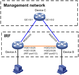
Applicable hardware and software versions
The following matrix shows the hardware and software versions to which this configuration example is applicable:
|
Hardware |
Software version |
|
S6850 switch series S9850 switch series |
Release 6555P01 |
|
S9820-64H switch |
Release 6555P01 |
Restrictions and guidelines
Management IP address configuration restrictions and guidelines
When you configure management IP addresses, follow these restrictions and guidelines:
· To make sure you can access the IRF fabric at the same IP address after a master/subordinate switchover, use the ip address ip-address { mask-length | mask } command to configure a management IP address on the management port, in this example, on M-GigabitEthernet 0/0/0. You can use this address to access the IRF fabric as long as the fabric has not split. This address might be inaccesible for an IP conflict after the IRF fabric splits, because it exists on all member devices. In the context of IRF, this address is called a global management IP address.
· To access each member device for failure recovery after the IRF fabric splits, use the ip address ip-address { mask-length | mask } irf-member member-id command to configure a management IP address for each member device on the management port, in this example, on M-GigabitEthernet 0/0/0. In the context of IRF, this address is called a member-specific management IP address.
· Make sure the management IP addresses assigned to all IRF member devices on the same management Ethernet port belong to the same subnet. Make sure the management IP addresses assigned to an IRF member device on different management Ethernet ports belong to different subnets.
· You must manually make sure the management IP addresses configured on the subordinate devices will not cause IP address conflicts on the network. When the IRF fabric is running correctly, only the IP addresses of the management Ethernet ports on the master device take effect. The management IP addresses of the management Ethernet ports on the subordinate devices do not take effect. If a management IP address on a subordinate device conflicts with an IP address in the network, the system cannot detect the IP conflict, causing network issues after an IRF split.
|
|
NOTE: When the IRF fabric is integrated, you can access the IRF fabric by using either the global management IP address or the management IP address specific to the master device. As a best practice to prevent the management IP address from changing upon a master/subordinate switchover, use the global management IP address as long as the IRF fabric is integrated. |
ARP MAD configuration restrictions and guidelines
When you configure ARP MAD on a management Ethernet port, follow these restrictions and guidelines:
|
Category |
Restrictions and guidelines |
|
Management Ethernet ports for ARP MAD |
Connect a management Ethernet port on each member device to the common Ethernet ports on the intermediate device. |
|
ARP MAD VLAN |
On the intermediate device, create a VLAN for ARP MAD, and assign the ports used for ARP MAD to the VLAN. On the IRF fabric, you do not need to assign the management Ethernet ports to the VLAN. |
|
ARP MAD and feature configuration |
· Enable the IRF fabric to change its bridge MAC address as soon as the address owner leaves. · If the intermediate device is also an IRF fabric, assign the two IRF fabrics different domain IDs for correct split detection. |
Procedures
Setting up the IRF fabric
1. Configure Device A:
# Shut down the physical interfaces used for IRF connection. This example uses HundredGigE 1/0/25 and HundredGigE 1/0/26 for IRF connection.
<DeviceA> system-view
[DeviceA] interface range hundredgige 1/0/25 to hundredgige 1/0/26
[DeviceA-if-range] shutdown
[DeviceA-if-range] quit
# Bind HundredGigE 1/0/25 and HundredGigE 1/0/26 to IRF-port 1/2.
[DeviceA] irf-port 1/2
[DeviceA-irf-port1/2] port group interface hundredgige 1/0/25
[DeviceA-irf-port1/2] port group interface hundredgige 1/0/26
[DeviceA-irf-port1/2] quit
# Bring up the physical interfaces.
[DeviceA] interface range hundredgige 1/0/25 to hundredgige 1/0/26
[DeviceA-if-range] undo shutdown
[DeviceA-if-range] quit
# Save the running configuration to the next-startup configuration file.
[DeviceA] quit
<DeviceA> save
# Activate the IRF port configuration.
<DeviceA> system-view
[DeviceA] irf-port-configuration active
2. Configure Device B:
# Assign member ID 2 to Device B, and reboot the device to have the change take effect.
<DeviceB> system-view
[DeviceB] irf member 1 renumber 2
Renumbering the member ID may result in configuration change or loss. Continue? [Y/N]:y
[DeviceB] quit
<DeviceB> reboot
# Shut down the physical interfaces used for IRF connection. This example uses HundredGigE 2/0/25 and HundredGigE 2/0/26 for IRF connection.
<DeviceB> system-view
[DeviceB] interface range hundredgige 2/0/25 to hundredgige 2/0/26
[DeviceB-if-range] shutdown
[DeviceB-if-range] quit
# Bind HundredGigE 2/0/25 and HundredGigE 2/0/26 to IRF-port 2/1.
[DeviceB] irf-port 2/1
[DeviceB-irf-port2/1] port group interface hundredgige 2/0/25
[DeviceB-irf-port2/1] port group interface hundredgige 2/0/26
[DeviceB-irf-port2/1] quit
# Bring up the physical interfaces.
[DeviceB] interface range hundredgige 2/0/25 to hundredgige 2/0/26
[DeviceB-if-range] undo shutdown
[DeviceB-if-range] quit
# Save the running configuration to the next-startup configuration file.
[DeviceB] quit
<DeviceB> save
# Connect Device B to Device A, as shown in Figure 13.
# Activate the IRF port configuration.
<DeviceB> system-view
[DeviceB] irf-port-configuration active
Device A and Device B perform master election. The device that has failed master election automatically reboots to form an IRF fabric with the other device. A two-chassis IRF fabric is formed.
Configuring management IP addresses
# Assign IP address 192.168.1.1/24 to the IRF fabric on management Ethernet port M-GigabitEthernet 0/0/0.
<IRF> system-view
[IRF] interface m-gigabitethernet 0/0/0
[IRF-M-GigabitEthernet0/0/0] ip address 192.168.1.1 24
# On management Ethernet port M-GigabitEthernet 0/0/0, assign IP addresses 192.168.1.101/24 and 192.168.1.102/24 to IRF member device 1 (Device A) and IRF member device 2 (Device B), respectively. After the IRF fabric splits, the administrator can use IP addresses 192.168.1.101/24 and 192.168.1.102/24 to log in to Device A and Device B, respectively.
[IRF-M-GigabitEthernet0/0/0] ip address 192.168.1.101 24 irf-member 1
[IRF-M-GigabitEthernet0/0/0] ip address 192.168.1.102 24 irf-member 2
[IRF-M-GigabitEthernet0/0/0] quit
# Exclude management Ethernet port M-GigabitEthernet 0/0/0 from being shut down by MAD upon detection of multi-active collisions.
[IRF] mad exclude interface m-gigabitethernet 0/0/0
Configuring ARP MAD
1. Configure the IRF fabric:
# Configure the IRF fabric to change its bridge MAC address as soon as the address owner leaves.
[IRF] undo irf mac-address persistent
# Set the domain ID of the IRF fabric to 1.
[IRF] irf domain 1
# Enable ARP MAD on management Ethernet port M-GigabitEthernet 0/0/0.
[IRF] interface m-gigabitethernet 0/0/0
[IRF-M-GigabitEthernet0/0/0] mad arp enable
You need to assign a domain ID (range: 0-4294967295)
[Current domain ID is: 1]:
The assigned domain ID is: 1
[IRF-M-GigabitEthernet0/0/0] quit
# Save the running configuration to the next-startup configuration file.
[IRF] save
2. Configure Device C as the intermediate device:
# Create VLAN 100.
<DeviceC> system-view
[DeviceC] vlan 100
# Assign GigabitEthernet 1/0/1 and GigabitEthernet 1/0/2 to VLAN 100 for forwarding ARP MAD packets.
[DeviceC-vlan100] port gigabitethernet 1/0/1 to gigabitethernet 1/0/2
[DeviceC-vlan100] quit
Verifying the configuration
# Disconnect the IRF links between Device A and Device B. Verify that you can use 192.168.1.101 and 192.168.1.102 to log in to Device A and Device B, respectively. (Details not shown.)
# Execute the display mad verbose command on Device A and Device B to verify that MAD is correctly functioning, as follows:
· The Multi-active recovery state field displays Yes on one device and displays No on the other device.
· On each device, the IRF physical interfaces and management Ethernet port M-GigabitEthernet 0/0/0 are excluded from being shut down by MAD.
# Execute the display interface brief command on Device A and Device B to verify that the MAD shutdown action is performed correctly, as follows:
· On the device in Recovery state, all network interfaces have been shut down by MAD except the IRF physical interfaces and management Ethernet port M-GigabitEthernet 0/0/0.
· On the device not in Recovery state, no network interfaces are shut down by MAD.
Configuration files
· IRF fabric:
#
irf-port 1/2
port group interface HundredGigE1/0/25
port group interface HundredGigE1/0/26
#
irf-port 2/1
port group interface HundredGigE2/0/25
port group interface HundredGigE2/0/26
#
irf domain 1
undo irf mac-address persistent
#
interface M-GigabitEthernet0/0/0
ip address 192.168.1.1 255.255.255.0
ip address 192.168.1.101 255.255.255.0 irf-member 1
ip address 192.168.1.102 255.255.255.0 irf-member 2
mad arp enable
#
mad exclude interface M-GigabitEthernet0/0/0
#
· Device C:
#
vlan 100
#
GigabitEthernet 1/0/1
port access vlan 100
#
Gigabitethernet 1/0/2
port access vlan 100
#
Example: Setting up a two-chassis IRF fabric with BFD MAD and management IP configured on separate management Ethernet ports
|
|
IMPORTANT: This example is also applicable to a two-chassis IRF fabric running ARP MAD or ND MAD, except that you must configure ARP MAD and ND MAD differently. For more information about MAD configuration, see the virtual technologies configuration guide for the device. |
Network configuration
As shown in Figure 14, use Device A and Device B to set up a two-chassis IRF fabric.
Use management Ethernet port M-GigabitEthernet 0/0/0 on Device A and Device B for device management purposes. Configure management IP addresses for the IRF fabric and each member device on the management port to meet the following requirements:
· The administrator can use the same management IP address to access the IRF fabric before and after an active/subordinate switchover.
· The administrator can access each member device for failure recovery through their respective management IP addresses after the IRF fabric splits.
Use management Ethernet port M-GigabitEthernet 0/0/1 to perform BFD MAD for IRF split detection.
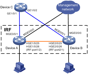
Applicable hardware and software versions
The following matrix shows the hardware and software versions to which this configuration example is applicable:
|
Hardware |
Software version |
|
S6850 switch series S9850 switch series |
Release 6555P01 |
|
S9820-64H switch |
Release 6555P01 |
Restrictions and guidelines
Management IP address configuration restrictions and guidelines
When you configure management IP addresses, follow these restrictions and guidelines:
· To make sure you can access the IRF fabric at the same IP address after a master/subordinate switchover, use the ip address ip-address { mask-length | mask } command to configure a management IP address on the management port, in this example, on M-GigabitEthernet 0/0/0. You can use this address to access the IRF fabric as long as the fabric has not split. This address might be inaccesible for an IP conflict after the IRF fabric splits, because it exists on all member devices. In the context of IRF, this address is called a global management IP address.
· To access each member device for failure recovery after the IRF fabric splits, use the ip address ip-address { mask-length | mask } irf-member member-id command to configure a management IP address for each member device on the management port, in this example, on M-GigabitEthernet 0/0/0. In the context of IRF, this address is called a member-specific management IP address.
· Make sure the management IP addresses assigned to all IRF member devices on the same management Ethernet port belong to the same subnet. Make sure the management IP addresses assigned to an IRF member device on different management Ethernet ports belong to different subnets.
· You must manually make sure the management IP addresses configured on the subordinate devices will not cause IP address conflicts on the network. When the IRF fabric is running correctly, only the IP addresses of the management Ethernet ports on the master device take effect. The management IP addresses of the management Ethernet ports on the subordinate devices do not take effect. If a management IP address on a subordinate device conflicts with an IP address in the network, the system cannot detect the IP conflict, causing network issues after an IRF split.
|
|
NOTE: When the IRF fabric is integrated, you can access the IRF fabric by using either the global management IP address or the management IP address specific to the master device. As a best practice to prevent the management IP address from changing upon a master/subordinate switchover, use the global management IP address as long as the IRF fabric is integrated. |
BFD MAD configuration restrictions and guidelines
When you configure BFD MAD on a management Ethernet port, follow these restrictions and guidelines:
|
Category |
Restrictions and guidelines |
|
Management Ethernet ports for BFD MAD |
Connect a management Ethernet port on each IRF member device to the common Ethernet ports on the intermediate device. |
|
BFD MAD VLAN |
· On the intermediate device, create a VLAN for BFD MAD, and assign the ports used for BFD MAD to the VLAN. On the IRF fabric, you do not need to assign the management Ethernet ports to the VLAN. · Make sure the IRF fabrics on the network use different BFD MAD VLANs. · Make sure the BFD MAD VLAN on the intermediate device contains only ports on the BFD MAD links. |
|
MAD IP address |
· To avoid network issues, only use the mad ip address command to configure IP addresses on the BFD MAD-enabled management Ethernet port. Do not configure an IP address by using the ip address command or configure a VRRP virtual address on the BFD MAD-enabled management Ethernet port. · Make sure all the MAD IP addresses are on the same subnet. |
Procedures
Setting up the IRF fabric
1. Configure Device A:
# Shut down the physical interfaces used for IRF connection. This example uses HundredGigE 1/0/25 and HundredGigE 1/0/26 for IRF connection.
<DeviceA> system-view
[DeviceA] interface range hundredgige 1/0/25 to hundredgige 1/0/26
[DeviceA-if-range] shutdown
[DeviceA-if-range] quit
# Bind HundredGigE 1/0/25 and HundredGigE 1/0/26 to IRF-port 1/2.
[DeviceA] irf-port 1/2
[DeviceA-irf-port1/2] port group interface hundredgige 1/0/25
[DeviceA-irf-port1/2] port group interface hundredgige 1/0/26
[DeviceA-irf-port1/2] quit
# Bring up the physical interfaces.
[DeviceA] interface range hundredgige 1/0/25 to hundredgige 1/0/26
[DeviceA-if-range] undo shutdown
[DeviceA-if-range] quit
# Save the running configuration to the next-startup configuration file.
[DeviceA] quit
<DeviceA> save
# Activate the IRF port configuration.
<DeviceA> system-view
[DeviceA] irf-port-configuration active
2. Configure Device B:
# Assign member ID 2 to Device B, and reboot the device to have the change take effect.
<DeviceB> system-view
[DeviceB] irf member 1 renumber 2
Renumbering the member ID may result in configuration change or loss. Continue? [Y/N]:y
[DeviceB] quit
<DeviceB> reboot
# Shut down the physical interfaces used for IRF connection. This example uses HundredGigE 2/0/25 and HundredGigE 2/0/26 for IRF connection.
<DeviceB> system-view
[DeviceB] interface range hundredgige 2/0/25 to hundredgige 2/0/26
[DeviceB-if-range] shutdown
[DeviceB-if-range] quit
# Bind HundredGigE 2/0/25 and HundredGigE 2/0/26 to IRF-port 2/1.
[DeviceB] irf-port 2/1
[DeviceB-irf-port2/1] port group interface hundredgige 2/0/25
[DeviceB-irf-port2/1] port group interface hundredgige 2/0/26
[DeviceB-irf-port2/1] quit
# Bring up the physical interfaces.
[DeviceB] interface range hundredgige 2/0/25 to hundredgige 2/0/26
[DeviceB-if-range] undo shutdown
[DeviceB-if-range] quit
# Save the running configuration to the next-startup configuration file.
[DeviceB] quit
<DeviceB> save
# Connect Device B to Device A, as shown in Figure 14.
# Activate the IRF port configuration.
<DeviceB> system-view
[DeviceB] irf-port-configuration active
Device A and Device B perform master election. The device that has failed master election automatically reboots to form an IRF fabric with the other device.
Configuring management IP addresses
# Assign IP address 192.168.1.1/24 to the IRF fabric on management Ethernet port M-GigabitEthernet 0/0/0.
<IRF> system-view
[IRF] interface m-gigabitethernet 0/0/0
[IRF-M-GigabitEthernet0/0/0] ip address 192.168.1.1 24
# On management Ethernet port M-GigabitEthernet 0/0/0, assign IP addresses 192.168.1.101/24 and 192.168.1.102/24 to IRF member device 1 (Device A) and IRF member device 2 (Device B), respectively. After the IRF fabric splits, the administrator can use IP addresses 192.168.1.101/24 and 192.168.1.102/24 to log in to Device A and Device B, respectively.
[IRF-M-GigabitEthernet0/0/0] ip address 192.168.1.101 24 irf-member 1
[IRF-M-GigabitEthernet0/0/0] ip address 192.168.1.102 24 irf-member 2
[IRF-M-GigabitEthernet0/0/0] quit
# Exclude management Ethernet port M-GigabitEthernet 0/0/0 from being shut down by MAD upon detection of multi-active collisions.
[IRF] mad exclude interface m-gigabitethernet 0/0/0
Configuring BFD MAD
1. Configure the IRF fabric:
# Assign a MAD IP address to each IRF member device on management Ethernet port M-GigabitEthernet 0/0/1.
[IRF] interface m-gigabitethernet 0/0/1
[IRF-M-GigabitEthernet0/0/1] mad ip address 192.168.2.1 24 member 1
[IRF-M-GigabitEthernet0/0/1] mad ip address 192.168.2.2 24 member 2
# Enable BFD MAD on management Ethernet port M-GigabitEthernet 0/0/1.
[IRF-M-GigabitEthernet0/0/1] mad bfd enable
[IRF-M-GigabitEthernet0/0/1] quit
# Save the running configuration to the next-startup configuration file.
[IRF] save
2. Configure Device C as the intermediate device:
# Create VLAN 100.
<DeviceC> system-view
[DeviceC] vlan 100
# Assign GigabitEthernet 1/0/1 and GigabitEthernet 1/0/2 to VLAN 100 for forwarding BFD MAD packets.
[DeviceC-vlan100] port gigabitethernet 1/0/1 to gigabitethernet 1/0/2
[DeviceC-vlan100] quit
Verifying the configuration
# Disconnect the IRF links between Device A and Device B. Verify that you can use 192.168.1.101 and 192.168.1.102 to log in to Device A and Device B, respectively. (Details not shown.)
# Execute the display mad verbose command on Device A and Device B to verify that MAD is correctly functioning, as follows:
· The Multi-active recovery state field displays Yes on one device and displays No on the other device.
· On each device, the following network interfaces are excluded from being shut down by MAD:
¡ The IRF physical interfaces.
¡ Management Ethernet ports M-GigabitEthernet 0/0/0 and M-GigabitEthernet 0/0/1.
# Execute the display interface brief command on Device A and Device B to verify that the MAD shutdown action is performed correctly, as follows:
· On the device in Recovery state, all network interfaces have been shut down by MAD except the IRF physical interfaces and management Ethernet ports M-GigabitEthernet 0/0/0 and M-GigabitEthernet 0/0/1.
· On the device not in Recovery state, no network interfaces are shut down by MAD.
Configuration files
· IRF fabric:
#
irf-port 1/2
port group interface HundredGigE1/0/25
port group interface HundredGigE1/0/26
#
irf-port 2/1
port group interface HundredGigE2/0/25
port group interface HundredGigE2/0/26
#
interface M-GigabitEthernet0/0/0
ip address 192.168.1.1 255.255.255.0
ip address 192.168.1.101 255.255.255.0 irf-member 1
ip address 192.168.1.102 255.255.255.0 irf-member 2
#
interface M-GigabitEthernet0/0/1
mad bfd enable
mad ip address 192.168.2.1 255.255.255.0 member 1
mad ip address 192.168.2.2 255.255.255.0 member 2
#
mad exclude interface M-GigabitEthernet0/0/0
#
· Device C:
#
vlan 100
#
GigabitEthernet 1/0/1
port access vlan 100
#
Gigabitethernet 1/0/2
port access vlan 100
#
Related documentation
· H3C S6850 & S9850 Switch Series Virtual Technologies Configuration Guide-Release 655x
· H3C S6850 & S9850 Switch Series Virtual Technologies Command Reference-Release 655x
· H3C S9820-64H Switch Virtual Technologies Configuration Guide-Release 655x
· H3C S9820-64H Switch Virtual Technologies Command Reference-Release 655x