- Table of Contents
- Related Documents
-
| Title | Size | Download |
|---|---|---|
| 10-PoE Configuration | 271.63 KB |
PoE configuration
Overview
Power over Ethernet (PoE) means that power sourcing equipment (PSE) supplies power to powered devices (PDs) from Ethernet interfaces through twisted pair cables.
|
|
NOTE: For more information about PoE, see H3C WX3000E Series Wireless Switches Switching Engine Configuration Guide. |
Configuring PoE ports
|
|
CAUTION: Before configure PoE, make sure the PoE power supply and PSE is operating normally. Otherwise, you cannot configure PoE or the configured PoE function does not take effect. |
1. Select PoE > PoE from the navigation tree.
2. Click the Port Setup tab.
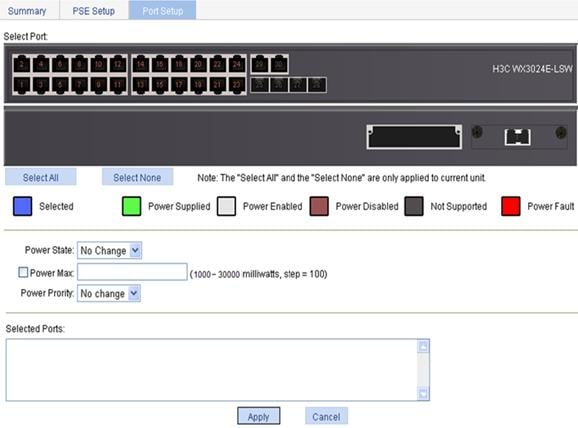
3. Configure the PoE ports as described in Table 1.
4. Click Apply.
|
Item |
Description |
|
Select Port |
Click to select ports to be configured and they will be displayed in the Selected Ports area. |
|
Power State |
Enable or disable PoE on the selected ports. · The system does not supply power to or reserve power for the PD connected to a PoE port if the PoE port is not enabled with the PoE function. · You are allowed to enable PoE for a PoE port if the PoE port will not result in PoE power overload; otherwise, you are not allowed to enable PoE for the PoE port. By default, PoE is disabled on a PoE port.
PSE power overload: When the sum of the power consumption of all ports exceeds the maximum power of PSE, the system considers the PSE is overloaded. |
|
Power Max |
Set the maximum power for the PoE port. The maximum PoE port power is the maximum power that the PoE port can provide to the connected PD. If the power required by the PD is larger than the maximum PoE port power, the PoE port will not supply power to the PD. By default, the maximum power of a PoE port is 30000 milliwatts. |
|
Power Priority |
Set the power supply priority for a PoE port. The priority levels of a PoE port include low, high, and critical in ascending order. · When the PoE power is insufficient, power is first supplied to PoE ports with a higher priority level. · When the PSE power is overloaded, the PoE port with a lower priority is first disconnected to guarantee the power supply to the PD with a higher priority. · If you set the priority of a PoE port to critical, the system compares the guaranteed remaining PSE power (the maximum PSE power minus the maximum power allocated to the existing critical PoE port, regardless of whether PoE is enabled for the PoE port) with the maximum power of this PoE port. If the former is greater than the latter, you can succeed in setting the priority to critical, and this PoE port will preempt the power of other PoE ports with a lower priority level; otherwise, you will fail to set the PoE port to critical. In the former case, the PoE ports whose power is preempted will be powered off, but their configurations will remain unchanged. When you change the priority of a PoE port from critical to a lower level, the PDs connecting to other PoE ports will have an opportunity of being powered. By default, the power priority of a PoE port is low.
· 19 watts guard band is reserved for each PoE port on the device to prevent a PD from being powered off because of a sudden increase of the PD power. When the remaining power of the PSE is lower than 19 watts, the port with a higher priority can preempt the power of the port with a lower priority to ensure the normal working of the higher priority port. · If the sudden increase of the PD power results in PSE power overload, power supply to the PD on the PoE interface with a lower priority will be stopped to ensure the power supply to the PD with a higher priority. |
Configuring non-standard PD detection
1. Select PoE > PoE from the navigation tree.
2. Click the PSE Setup tab to enter the page shown in Figure 2. The page displays the location of all PSEs, and the status of the non-standard PD detection function.

3. To enable the non-standard PD detection function of a specified PSE:
a. Select Enable in the corresponding Non-Standard PD Compatibility column of the target PSE.
b. Click Apply.
4. To disable the non-standard PD detection function of a specified PSE:
a. Select Disable in the corresponding Non-Standard PD Compatibility column of the target PSE.
b. Click Apply.
5. To enable the non-standard PD detection for all PSEs, click Enable All.
6. To disable the non-standard PD detection for all PSEs, click Disable All.
Displaying information about PSE and PoE ports
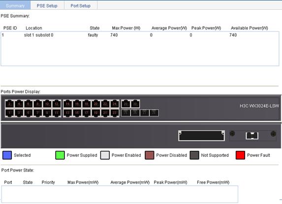
1. Select PoE > PoE from the navigation tree.
2. On the Summary tab, the upper part displays the PSE summary. To view the configuration and power information, click a port on the chassis front panel.
Figure 3 PoE summary (with GigabitEthernet 1/0/1 selected)
PoE configuration example
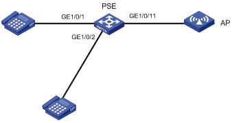
Network requirements
· As shown in Figure 4, GigabitEthernet 1/0/1 and GigabitEthernet 1/0/2 are connected to IP telephones.
· GigabitEthernet 1/0/11 is connected to AP whose maximum power does not exceed 9000 milliwatts.
· The power supply priority of IP telephones is higher than that of AP; therefore, the PSE supplies power to IP telephones first when the PSE power is overloaded.
Configuration procedure
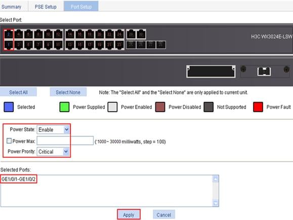
1. Enable PoE on GigabitEthernet 1/0/1 and GigabitEthernet 1/0/2, and configure their power supply priority as critical.
a. Select PoE > PoE from the navigation tree.
b. Click the Setup tab.
c. On the page that appears, select ports GigabitEthernet 1/0/1 and GigabitEthernet 1/0/2 from the chassis front panel, select Enable from the Power State list, select Critical from the Power Priority list, and click Apply.
Figure 5 Configuring the PoE ports supplying power to the IP telephones
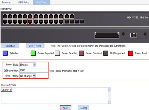
2. Enable PoE on GigabitEthernet 1/0/11 and configure the maximum power of the port as 9000 milliwatts.
a. Click the Setup tab.
b. On the page that appears, select port GigabitEthernet 1/0/11 from the chassis front panel, select Enable from the Power State list, select the box before Power Max and enter 9000, and click Apply.
Figure 6 Configuring the PoE port supplying power to AP
After the configuration takes effect, the IP telephones and AP are powered and can work properly.