- Table of Contents
- Related Documents
-
| Title | Size | Download |
|---|---|---|
| 09-QoS Configuration | 499.91 KB |
Contents
Recommended ACL configuration procedures
Configuring a rule for a basic IPv4 ACL
Configuring a rule for an advanced IPv4 ACL
Configuring a rule for an Ethernet frame header ACL
Configuring a rule for a basic IPv6 ACL
Configuring a rule for an advanced IPv6 ACL
Recommended QoS configuration procedures
Configuring classification rules
Configuring traffic mirroring and traffic redirecting for a traffic behavior
Configuring other actions for a traffic behavior
Configuring classifier-behavior associations for the policy
Configuring queue scheduling on a port
Configuring line rate on a port
Configuring priority mapping tables
Configuring priority trust mode on a port
ACL and QoS configuration example
|
|
NOTE: Unless otherwise stated, ACLs refer to both IPv4 and IPv6 ACLs throughout this document.. |
Overview
ACL overview
An access control list (ACL) is a set of rules (or permit or deny statements) for identifying traffic based on criteria such as source IP address, destination IP address, and port number.
ACLs are essentially used for packet filtering. A packet filter drops packets that match a deny rule and permits packets that match a permit rule. ACLs are also widely used by many modules, for example, QoS and IP routing, for traffic identification.
ACLs fall into the following categories.
|
Category |
ACL number |
IP version |
Match criteria |
|
Basic ACLs |
2000 to 2999 |
IPv4 |
Source IPv4 address |
|
IPv6 |
Source IPv6 address |
||
|
Advanced ACLs |
3000 to 3999 |
IPv4 |
Source/destination IPv4 address, protocols over IPv4, and other Layer 3 and Layer 4 header fields |
|
IPv6 |
Source/destination IPv6 address, protocols over IPv6, and other Layer 3 and Layer 4 header fields |
||
|
Ethernet frame header ACLs |
4000 to 4999 |
IPv4 and IPv6 |
Layer 2 header fields, such as source and destination MAC addresses, 802.1p priority, and link layer protocol type |
|
|
NOTE: For more information about ACLs, see H3C WX3000E Wired-Wireless Switch Switching Engine Configuration Guide. |
QoS overview
Quality of Service (QoS) is a concept concerning service demand and supply. It reflects the ability to meet customer needs. Generally, QoS does not focus on grading services precisely, but on improving services under certain conditions.
In the internet, QoS refers to the ability of the network to forward packets. The evaluation on QoS of a network can be based on different aspects because the network may provide various services. Generally, QoS refers to the ability to provide improved service by solving the core issues such as delay, jitter, and packet loss ratio in the packet forwarding process.
Traditional packet forwarding services
On traditional IP networks, devices treat all packets equally and handle them using the first in first out (FIFO) policy. All packets share the resources of the network and devices. How many resources the packets can obtain completely depends on the time they arrive. This service is called “best-effort”. It delivers packets to their destinations as possibly as it can, without any guarantee for delay, jitter, packet loss ratio, reliability and so on.
This service policy is only suitable for applications insensitive to bandwidth and delay, such as WWW, file transfer and email.
New requirements from new applications
The Internet has been growing along with the fast development of networking technologies. More and more users take the Internet as their data transmission platform to implement various applications.
Besides traditional applications such as WWW, email and FTP, network users are experiencing new services, such as tele-education, telemedicine, video telephone, videoconference and Video-on-Demand (VoD). The enterprise users expect to connect their regional branches together through VPN technologies to carry out operational applications, for instance, to access the database of the company or to monitor remote devices through Telnet.
These new applications have one thing in common, and they all have special requirements for bandwidth, delay, and jitter. For instance, videoconference and VoD need large bandwidth, low delay and jitter. As for mission-critical applications, such as transactions and Telnet, they may not require large bandwidth but do require low delay and preferential service during congestion.
The new emerging applications demand higher service performance of IP networks. Better network services during packets forwarding are required, such as providing dedicated bandwidth, reducing packet loss ratio, managing and avoiding congestion, regulating network traffic, and setting the precedence of packets. To meet these requirements, networks must provide more improved services.
|
|
NOTE: For more information about QoS, see H3C WX3000E Wired-Wireless Switch Switching Engine Configuration Guide. |
Configuring an ACL
Recommended ACL configuration procedures
Recommended IPv4 ACL configuration procedure
|
Step |
Remarks |
|
Optional Create a time range. A rule referencing a time range takes effect only during the specified time range. |
|
|
Required Create an IPv4 ACL. The category of the created ACL depends on the ACL number that you specify. |
|
|
Required Complete one of the following tasks according to the ACL category. |
|
Recommended IPv6 ACL configuration procedure
|
Step |
Remarks |
|
Optional Create a time range. A rule referencing a time range takes effect only during the specified time range. |
|
|
Required Create an IPv6 ACL. The category of the created IPv6 ACL depends on the ACL number that you specify. |
|
|
Required Complete one of the tasks according to the ACL category. |
|
Configuring a time range
1. Select QoS > Time Range from the navigation tree.
2. Click the Create tab to enter the time range creating page.
Figure 1 The page for creating a time range
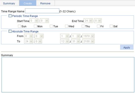
3. Configure the time range information.
4. Click Apply.
|
Item |
Description |
||
|
Time Range Name |
Set the name for the time range. |
||
|
Periodic Time Range |
Start Time |
Set the start time of the periodic time range. |
You can define both a periodic time range and an absolute time range to create a compound time range. This compound time range recurs on the day or days of the week only within the specified period. |
|
End Time |
Set the end time of the periodic time range. The end time must be greater than the start time. |
||
|
Sun, Mon, Tue, Wed, Thu, Fri, and Sat. |
Select the day or days of the week on which the periodic time range is valid. You can select any combination of the days of the week. |
||
|
Absolute Time Range |
From |
Set the start time and date of the absolute time range. The time of the day is in the hh:mm format (24-hour clock), and the date is in the MM/DD/YYYY format. |
|
|
To |
Set the end time and date of the absolute time range. The time of the day is in the hh:mm format (24-hour clock), and the date is in the MM/DD/YYYY format. The end time must be greater than the start time. |
||
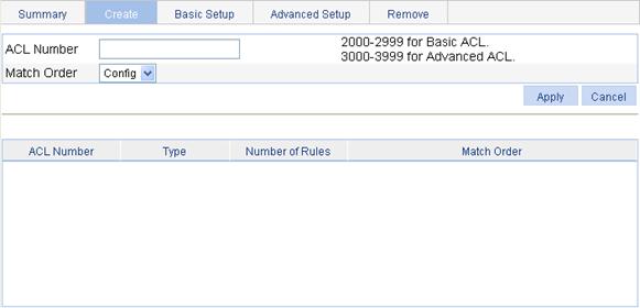
Creating an IPv4 ACL
1. Select QoS > ACL IPv4 from the navigation tree.
2. Click the Create tab to enter the IPv4 ACL creating page, as shown in Figure 2.
Figure 2 The page for creating an IPv4 ACL
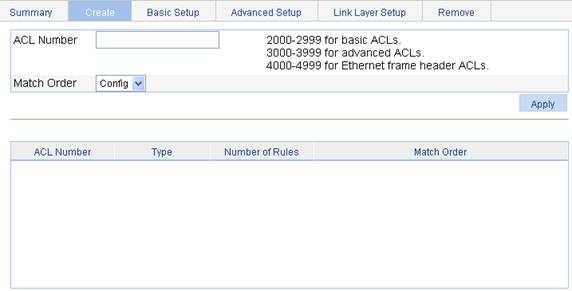
3. Configure the IPv4 ACL information.
4. Click Apply.
|
Item |
Description |
|
ACL Number |
Set the number of the IPv4 ACL. |
|
Match Order |
Set the match order of the ACL. Available values are: · Config—Packets are compared against ACL rules in the order that the rules are configured. · Auto—Packets are compared against ACL rules in the depth-first match order. |
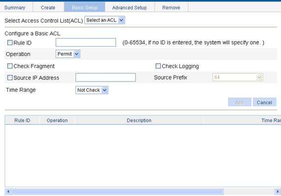
Configuring a rule for a basic IPv4 ACL
1. Select QoS > ACL IPv4 from the navigation tree.
2. Click the Basic Setup tab to enter the rule configuration page for a basic IPv4 ACL, as shown in Figure 3.
Figure 3 The page for configuring an basic IPv4 ACL
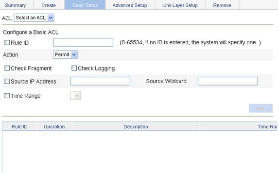
3. Configure a basic IPv4 ACL.
4. Click Add.
|
Item |
Description |
|
ACL |
Select the basic IPv4 ACL for which you want to configure rules. Available ACLs are basic IPv4 ACLs. |
|
Rule ID |
Select the Rule ID option and enter a number for the rule. If you do not specify the rule number, the system will assign one automatically.
If the rule number you specify already exists, the following operations modify the configuration of the rule. |
|
Action |
Select the action to be performed for IPv4 packets matching the rule. · Permit: Allows matched packets to pass. · Deny: Drops matched packets. |
|
Check Fragment |
Select this option to apply the rule to only non-first fragments. If you do no select this option, the rule applies to all fragments and non-fragments. |
|
Check Logging |
Select this option to keep a log of matched IPv4 packets. A log entry contains the ACL rule number, operation for the matched packets, protocol that IP carries, source/destination address, source/destination port number, and number of matched packets. |
|
Source IP Address |
Select the Source IP Address option and enter a source IPv4 address and a wildcard mask, in dotted decimal notation. |
|
Source Wildcard |
|
|
Time Range |
Select the time range during which the rule takes effect. |
Configuring a rule for an advanced IPv4 ACL
1. Select QoS > ACL IPv4 from the navigation tree.
2. Click the Advanced Setup tab to enter the rule configuration page for an advanced IPv4 ACL, as shown in Figure 4.
Figure 4 The page for configuring an advanced IPv4 ACL
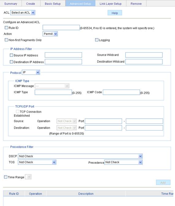
3. Configure an advanced IPv4 ACL rule.
4. Click Add.
|
Item |
Description |
|||
|
ACL |
Select the advanced IPv4 ACL for which you want to configure rules. Available ACLs are advanced IPv4 ACLs. |
|||
|
Rule ID |
Select the Rule ID option and enter a number for the rule. If you do not specify the rule number, the system will assign one automatically.
If the rule number you specify already exists, the following operations modify the configuration of the rule. |
|||
|
Action |
Select the action to be performed for packets matching the rule. · Permit: Allows matched packets to pass. · Deny: Drops matched packets. |
|||
|
Non-First Fragments Only |
Select this option to apply the rule to only non-first fragments. If you do no select this option, the rule applies to all fragments and non-fragments. |
|||
|
Logging |
Select this option to keep a log of matched packets. A log entry contains the ACL rule number, operation for the matched packets, protocol that IP carries, source/destination address, source/destination port number, and number of matched packets. |
|||
|
IP Address Filter |
Source IP Address |
Select the Source IP Address option and enter a source IPv4 address and a source wildcard mask, in dotted decimal notation. |
||
|
Source Wildcard |
||||
|
Destination IP Address |
Select the Source IP Address option and enter a source IP address and a source wildcard mask, in dotted decimal notation. |
|||
|
Destination Wildcard |
||||
|
Protocol |
Select the protocol to be carried by IP. If you select 1 ICMP, you can configure the ICMP message type and code; if you select 6 TCP or 17 UDP, you can configure the TCP or UDP port. |
|||
|
ICMP Type |
ICMP Message |
Specify the ICMP message type and code. These items are available only when you select 1 ICMP from the Protocol list. If you select Other from the ICMP Message list, you need to type values in the ICMP Type and ICMP Code fields. Otherwise, the two fields will take the default values, which cannot be changed. |
||
|
ICMP Type |
||||
|
ICMP Code |
||||
|
TCP/UDP Port |
TCP Connection Established |
Select this option to make the rule match packets used for establishing and maintaining TCP connections. These items are available only when you select 6 TCP from the Protocol list. |
||
|
Source |
Operator |
Select the operators and enter the source port numbers and destination port numbers as required. These items are available only when you select 6 TCP or 17 UDP from the Protocol list. Different operators have different configuration requirements for the port number fields: · Not Check: The following port number fields cannot be configured. · Range: The following port number fields must be configured to define a port range. · Other values: The first port number field must be configured and the second must not. |
||
|
Port |
||||
|
- |
||||
|
Destination |
Operator |
|||
|
Port |
||||
|
- |
||||
|
Precedence Filter |
DSCP |
Specify the DSCP value. |
If you specify the ToS precedence or IP precedence when you specify the DSCP value, the specified TOS or IP precedence does not take effect. |
|
|
TOS |
Specify the ToS preference. |
|||
|
Precedence |
Specify the IP precedence. |
|||
|
Time Range |
Select the time range during which the rule takes effect. |
|||
Configuring a rule for an Ethernet frame header ACL
1. Select QoS > ACL IPv4 from the navigation tree.
2. Click the Link Layer Setup tab to enter the rule configuration page for an Ethernet frame header IPv4 ACL, as shown in Figure 5.
Figure 5 The page for configuring a rule for an Ethernet frame header ACL
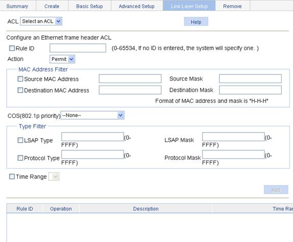
3. Configure an Ethernet frame header IPv4 ACL rule.
4. Click Add.
|
Item |
Description |
|
|
ACL |
Select the Ethernet frame header IPv4 ACL for which you want to configure rules. Available ACLs are Ethernet frame header IPv4 ACLs. |
|
|
Rule ID |
Select the Rule ID option and enter a number for the rule. If you do not specify the rule number, the system will assign one automatically.
If the rule number you specify already exists, the following operations modify the configuration of the rule. |
|
|
Action |
Select the action to be performed for packets matching the rule. · Permit: Allows matched packets to pass. · Deny: Drops matched packets. |
|
|
MAC Address Filter |
Source MAC Address |
Select the Source MAC Address option and enter a source MAC address and a mask. |
|
Source Mask |
||
|
Destination MAC Address |
Select the Destination MAC Address option and enter a destination MAC address and a mask. |
|
|
Destination Mask |
||
|
COS(802.1p priority) |
Specify the 802.1p priority for the rule. |
|
|
Type Filter |
LSAP Type |
Select the LSAP Type option and specify the DSAP and SSAP fields in the LLC encapsulation by configuring the following items: · LSAP Type: Indicates the frame encapsulation format. · LSAP Mask: Indicates the LSAP mask. |
|
LSAP Mask |
||
|
Protocol Type |
Select the Protocol Type option and specify the link layer protocol type by configuring the following items: · Protocol Type: Indicates the frame type. It corresponds to the type-code field of Ethernet_II and Ethernet_SNAP frames. · Protocol Mask: Indicates the protocol mask. |
|
|
Protocol Mask |
||
|
Time Range |
Select the time range during which the rule takes effect. |
|
Creating an IPv6 ACL
1. Select QoS > ACL IPv6 from the navigation tree.
2. Click the Create tab to enter the IPv6 ACL creating page, as shown in Figure 6.
Figure 6 The page for creating an IPv6 ACL
3. Configure the IPv6 ACL information.
4. Click Apply.
|
Item |
Description |
|
ACL Number |
Enter a number for the IPv6 ACL. |
|
Match Order |
Select a match order for the ACL. Available values are: · Config: Packets are compared against ACL rules in the order the rules are configured. · Auto: Packets are compared against ACL rules in the depth-first match order. |
Configuring a rule for a basic IPv6 ACL
1. Select QoS > ACL IPv6 from the navigation tree
2. Click the Basic Setup tab to enter the rule configuration page for a basic IPv6 ACL, as shown in Figure 7.
Figure 7 The page for configuring a rule for a basic IPv6 ACL
3. Configure the basic IPv6 ACL rule information.
4. Click Add.
|
Item |
Description |
|
Select Access Control List (ACL) |
Select the basic IPv6 ACL for which you want to configure rules. |
|
Rule ID |
Select the Rule ID option and enter a number for the rule. If you do not specify the rule number, the system will assign one automatically.
If the rule number you specify already exists, the following operations modify the configuration of the rule. |
|
Operation |
Select the operation to be performed for IPv6 packets matching the rule. · Permit: Allows matched packets to pass. · Deny: Drops matched packets. |
|
Check Fragment |
Select this option to apply the rule to only non-first fragments. If you do no select this option, the rule applies to all fragments and non-fragments. |
|
Check Logging |
Select this option to keep a log of matched IPv6 packets. A log entry contains the ACL rule number, operation for the matched packets, protocol that IP carries, source/destination address, source/destination port number, and number of matched packets. |
|
Source IP Address |
Select the Source IP Address option and enter a source IPv6 address and prefix length. The IPv6 address must be in a format like X:X::X:X. An IPv6 address consists of eight 16-bit long fields, each of which is expressed with two hexadecimal numbers and separated from its neighboring fields by colon (:). |
|
Source Prefix |
|
|
Time Range |
Select the time range during which the rule takes effect. |
Configuring a rule for an advanced IPv6 ACL
1. Select QoS > ACL IPv6 from the navigation tree
2. Click the Advanced Setup tab to enter the rule configuration page for an advanced IPv6 ACL, as shown in Figure 8.
Figure 8 The page for configuring a rule for an advanced IPv6 ACL
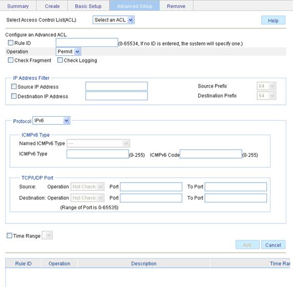
3. Configure the advanced IPv6 ACL rule information.
4. Click Add.
|
Item |
Description |
||
|
Select Access Control List (ACL) |
Select the advanced IPv6 ACL for which you want to configure rules. |
||
|
Rule ID |
Select the Rule ID option and enter a number for the rule. If you do not specify the rule number, the system will assign one automatically.
If the rule number you specify already exists, the following operations modify the configuration of the rule. |
||
|
Operation |
Select the operation to be performed for IPv6 packets matching the rule. · Permit: Allows matched packets to pass. · Deny: Drops matched packets. |
||
|
Check Fragment |
Select this option to apply the rule to only non-first fragments. If you do no select this option, the rule applies to all fragments and non-fragments. |
||
|
Check Logging |
Select this option to keep a log of matched IPv6 packets. A log entry contains the ACL rule number, operation for the matched packets, protocol that IP carries, source/destination address, source/destination port number, and number of matched packets. |
||
|
IP Address Filter |
Source IP Address |
Select the Source IP Address option and enter a source IPv6 address and prefix length. The IPv6 address must be in a format like X:X::X:X. An IPv6 address consists of eight 16-bit long fields, each of which is expressed with two hexadecimal numbers and separated from its neighboring fields by colon (:). |
|
|
Source Prefix |
|||
|
Destination IP Address |
Select the Destination IP Address option and enter a destination IPv6 address and prefix length. The IPv6 address must be in a format like X:X::X:X. An IPv6 address consists of eight 16-bit long fields, each of which is expressed with two hexadecimal numbers and separated from its neighboring fields by colon (:). |
||
|
Destination Prefix |
|||
|
Protocol |
Select the protocol to be carried by IP. If you select 58 ICMPv6, you can configure the ICMP message type and code; if you select 6 TCP or 17 UDP, you can configure the TCP or UDP specific items. |
||
|
ICMPv6 Type |
Named ICMPv6 Type |
Specify the ICMPv6 message type and code. These items are available only when you select 58 ICMPv6 from the Protocol list. If you select Other from the Named ICMPv6 Type list, you need to type values in the ICMPv6 Type and ICMPv6 Code fields. Otherwise, the two fields will take the default values, which cannot be changed. |
|
|
ICMPv6 Type |
|||
|
ICMPv6 Code |
|||
|
TCP/UDP Port |
Source |
Operator |
Select the operators and enter the source port numbers and destination port numbers as required. These items are available only when you select 6 TCP or 17 UDP from the Protocol list. Different operators have different configuration requirements for the port number fields: · Not Check: The following port number fields cannot be configured. · Range: The following port number fields must be configured to define a port range. · Other values: The first port number field must be configured and the second must not. |
|
Port |
|||
|
To Port |
|||
|
Destination |
Operator |
||
|
Port |
|||
|
Port |
|||
|
Time Range |
Select the time range during which the rule takes effect. |
||
QoS configuration
Recommended QoS configuration procedures
Recommended QoS policy configuration procedure
A QoS policy involves the following components: class, traffic behavior, and policy. You can associate a class with a traffic behavior using a QoS policy.
1. Class
Classes identify traffic.
A class is identified by a class name and contains some match criteria.
You can define a set of match criteria to classify packets. The relationship between criteria can be and or or.
· and: The device considers a packet belongs to a class only when the packet matches all the criteria in the class.
· or: The device considers a packet belongs to a class as long as the packet matches one of the criteria in the class.
2. Traffic behavior
A traffic behavior, identified by a name, defines a set of QoS actions for packets.
3. Policy
You can apply a QoS policy to a VLAN or a port.
· VLAN Policy: Applies a QoS policy to a VLAN to regulate all traffic of the VLAN. QoS policies cannot be applied to dynamic VLANs, such as VLANs generated by GVRP.
· Port Policy: Applies a QoS policy to a port to regulate the inbound or outbound traffic of the port. A QoS policy can be applied to multiple ports. Only one policy can be applied in one direction (inbound or outbound) of a port.
Table 10 Recommended QoS policy configuration procedure
|
Step |
Remarks |
|
Required Create a class and specify the logical relationship between the match criteria in the class. |
|
|
Required Configure match criteria for the class. |
|
|
Required Create a traffic behavior. |
|
|
4. Configuring traffic mirroring and traffic redirecting for a traffic behavior |
Use either approach Configure various actions for the traffic behavior. |
|
Required Create a policy. |
|
|
7. Configuring classifier-behavior associations for the policy |
Required Associate the traffic behavior with the class in the QoS policy. A class can be associated with only one traffic behavior in a QoS policy. Associating a class already associated with a traffic behavior will overwrite the old association. |
|
Required Apply the QoS policy to a port. |
Recommended queue scheduling configuration procedure
|
Step |
Remarks |
|
Optional Configure the queue scheduling mode for a port. The default queue scheduling mode of a port may vary depending on your device model. |
Recommended line rate configuration procedure
|
Step |
Remarks |
|
Required Limit the rate of incoming packets or outgoing packets of a physical port. |
Recommended priority mapping table configuration procedure
|
Step |
Remarks |
|
Required Set priority mapping tables. |
Recommended priority trust mode configuration procedure
|
Step |
Remarks |
|
Required Set the priority trust mode of a port. |
Creating a class
1. Select QoS > Classifier from the navigation tree.
2. Click the Create tab to enter the page for creating a class, as shown in Figure 9.
Figure 9 The page for creating a class
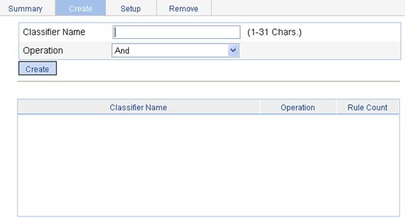
3. Configure the class information.
4. Click Create.
|
Item |
Description |
|
Classifier Name |
Specify a name for the classifier to be created. Some devices have their own system-defined classifiers. The classifier name you specify cannot overlap with system-defined ones. The system-defined classifiers include: default-class, ef, af1, af2, af3, af4, ip-prec0, ip-prec1, ip-prec2, ip-prec3, ip-prec4, ip-prec5, ip-prec6, ip-prec7, mpls-exp0, mpls-exp1, mpls-exp2, mpls-exp3, mpls-exp4, mpls-exp5, mpls-exp6, and mpls-exp7. |
|
Operator |
Specify the logical relationship between rules of the classifier. · And—Specifies the relationship between the rules in a class as logic AND. The device considers a packet belongs to a class only when the packet matches all the rules in the class. · Or—Specifies the relationship between the rules in a class as logic OR. The device considers a packet belongs to a class as long as the packet matches one of the rules in the class. |
Configuring classification rules
1. Select QoS > Classifier from the navigation tree.
2. Click the Setup tab to enter the page for setting a class, as shown in Figure 10.
Figure 10 The page for configuring classification rules
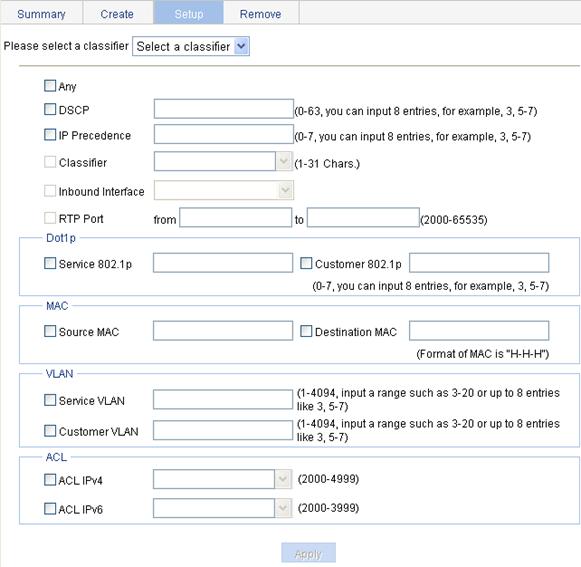
3. Configuration classification rules.
4. Click Apply.
A progress dialog box appears.
5. Click Close on the progress dialog box when the dialog box prompts that the configuration succeeds.
|
Item |
Description |
|
|
Please select a classifier |
Select an existing classifier in the list. |
|
|
Any |
Define a rule to match all packets. Select the option to match all packets. |
|
|
DSCP |
Define a rule to match DSCP values. If multiple such rules are configured for a class, the new configuration does not overwrite the previous one. You can configure up to eight DSCP values each time. If multiple identical DSCP values are specified, the system considers them as one. The relationship between different DSCP values is OR. After such configurations, all the DSCP values are arranged in ascending order automatically. |
|
|
IP Precedence |
Define a rule to match IP precedence values. If multiple such rules are configured for a class, the new configuration does not overwrite the previous one. You can configure up to eight IP precedence values each time. If multiple identical IP precedence values are specified, the system considers them as one. The relationship between different IP precedence values is OR. After such configurations, all the IP precedence values are arranged in ascending order automatically. |
|
|
Classifier |
Define a rule to match a QoS class. |
|
|
Inbound Interface |
Define a rule to match inbound interfaces. |
|
|
RTP Port |
Define a rule to match a range of RTP ports Specify the start port in the from field and the end port in the to field. |
|
|
Dot1p |
Service 802.1p |
Define a rule to match the service 802.1p priority values. If multiple such rules are configured for a class, the new configuration does not overwrite the previous one. You can configure up to eight 802.1p priority values each time. If multiple identical 802.1p priority values are specified, the system considers them as one. The relationship between different 802.1p priority values is OR. After such configurations, all the 802.1p priority values are arranged in ascending order automatically. |
|
Customer 802.1p |
Define a rule to match the customer 802.1p priority values. If multiple such rules are configured for a class, the new configuration does not overwrite the previous one. You can configure up to eight 802.1p priority values each time. If multiple identical 802.1p priority values are specified, the system considers them as one. The relationship between different 802.1p priority values is OR. After such configurations, all the 802.1p priority values are arranged in ascending order automatically. |
|
|
MAC |
Source MAC |
Define a rule to match a source MAC address. If multiple such rules are configured for a class, the new configuration does not overwrite the previous one. A rule to match a source MAC address is significant only to Ethernet interfaces. |
|
Destination MAC |
Define a rule to match a destination MAC address. If multiple such rules are configured for a class, the new configuration does not overwrite the previous one. A rule to match a destination MAC address is significant only to Ethernet interfaces. |
|
|
VLAN |
Service VLAN |
Define a rule to match service VLAN IDs. If multiple such rules are configured for a class, the new configuration does not overwrite the previous one. You can configure multiple VLAN IDs each time. If the same VLAN ID is specified multiple times, the system considers them as one. The relationship between different VLAN IDs is logical OR. After such a configuration. You can specify VLAN IDs in two ways: · Enter a range of VLAN IDs, such as 10-500. The number of VLAN IDs in the range is not limited. · Specify a combination of individual VLAN IDs and VLAN ID ranges, such as 3, 5-7, 10. You can specify up to eight VLAN IDs in this way. |
|
Customer VLAN |
Define a rule to match customer VLAN IDs. If multiple such rules are configured for a class, the new configuration does not overwrite the previous one. You can configure multiple VLAN IDs each time. If the same VLAN ID is specified multiple times, the system considers them as one. The relationship between different VLAN IDs is logical OR. You can specify VLAN IDs in two ways: · Enter a range of VLAN IDs, such as 10-500. The number of VLAN IDs in the range is not limited. · Specify a combination of individual VLAN IDs and VLAN ID ranges, such as 3, 5-7, 10. You can specify up to eight VLAN IDs in this way. |
|
|
ACL |
ACL IPv4 |
Define an IPv4 ACL-based rule. |
|
ACL IPv6 |
Define an IPv6 ACL-based rule.
Support for this configuration item depends on your device model. |
|
Creating a traffic behavior
1. Select QoS > Behavior from the navigation tree.
2. Click the Create tab to enter the page for creating a traffic behavior, as shown in Figure 11.
Figure 11 The page for creating a traffic behavior
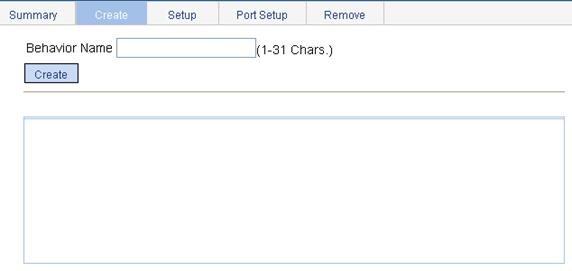
3. Set the traffic behavior name.
The behavior name you specify cannot overlap with system-defined ones. The system-defined behaviors include ef, af, and be.
4. Click Create.
Configuring traffic mirroring and traffic redirecting for a traffic behavior
1. Select QoS > Behavior from the navigation tree.
2. Click the Port Setup tab to enter the page for setting a traffic behavior, as shown in Figure 12.
Figure 12 Port setup page for a traffic behavior
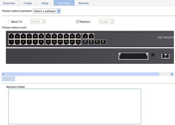
3. Configure the traffic mirroring and traffic redirecting actions.
4. Click Apply.
|
Item |
Description |
|
Please select a behavior |
Select an existing behavior in the list. |
|
Mirror To |
Set the action of mirroring traffic to the specified destination port.
The device supports mirroring traffic to only one interface. The new configuration overwrites the previous one. |
|
Redirect |
Set the action of redirecting traffic to the specified destination port. |
|
Please select a port |
Specify the port to be configured as the destination port of traffic mirroring or traffic directing on the chassis front panel. |
Configuring other actions for a traffic behavior
1. Select QoS > Behavior from the navigation tree.
2. Click the Setup tab to enter the page for setting a traffic behavior, as shown in Figure 13.
Figure 13 The page for setting a traffic behavior
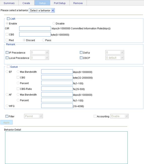
3. Configure other actions for the traffic behavior.
4. Click Apply.
A progress dialog box appears.
5. Click Close on the progress dialog box when the progress dialog box prompts that the configuration succeeds.
|
Item |
Description |
||
|
Please select a behavior |
Select an existing behavior in the list. |
||
|
CAR |
Enable/Disable |
Enable or disable CAR |
|
|
CIR |
Set the committed information rate (CIR), the average traffic rate. |
||
|
CBS |
Set the committed burst size (CBS), number of bytes that can be sent in each interval. |
||
|
Red |
Discard |
Set the action to perform for exceeding packets. After selecting the Red option, you can select one of the following options: · Discard: Drops the exceeding packet. · Pass: Permits the exceeding packet to pass through. |
|
|
Pass |
|||
|
Remark |
IP Precedence |
Configure the action of marking IP precedence for packets. Select the IP Precedence option and then select the IP precedence value to be marked for packets in the following list. Select Not Set to cancel the action of marking IP precedence. |
|
|
Dot1p |
Configure the action of marking 802.1p priority for packets. Select the Dot1p option and then select the 802.1p priority value to be marked for packets in the following list. Select Not Set to cancel the action of marking 802.1p priority. |
||
|
Local Precedence |
Configure the action of marking local precedence for packets. Select the Local Precedence option and then select the local precedence value to be marked for packets in the following list. Select Not Set to cancel the action of marking local precedence. |
||
|
DSCP |
Configure the action of marking DSCP value for packets. Select the DSCP option and then select the DSCP value to be marked for packets in the following list. Select Not Set to cancel the action of marking DSCP value. |
||
|
Queue |
EF |
Max Bandwidth |
Configure the maximum bandwidth for expedited forwarding (EF). |
|
CBS |
Configure the CBS for EF. |
||
|
Percent |
Configure the percent of available bandwidth for EF. |
||
|
CBS-Ratio |
Configure the ratio of CBS to CIR for EF. |
||
|
AF |
Min Bandwidth |
Configure the minimum guaranteed bandwidth for assured forwarding (AF). |
|
|
Percent |
Configure the percent of available bandwidth for AF. |
||
|
WFQ |
Configure WFQ for the default class by entering the total number of fair queues, which must be the power of two. |
||
|
Filter |
Configure the packet filtering action. After selecting the Filter option, select one item in the following list: · Permit: Forwards the packet. · Deny: Drops the packet. · Not Set: Cancels the packet filtering action. |
||
|
Accounting |
Configure the traffic accounting action. Select the Accounting option and select Enable or Disable in the following list to enable/disable the traffic accounting action. |
||
Creating a policy
1. Select QoS > QoS Policy from the navigation tree.
2. Click the Create tab to enter the page for creating a policy, as shown in Figure 14.
Figure 14 The page for creating a policy
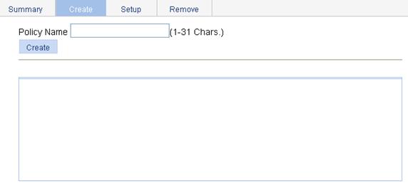
4. Click Create.
|
Item |
Description |
|
Policy Name |
Specify a name for the policy to be created. Some devices have their own system-defined policies. The policy name you specify cannot overlap with system-defined ones. The system-defined policy is the policy default. |
Configuring classifier-behavior associations for the policy
1. Select QoS > QoS Policy from the navigation tree.
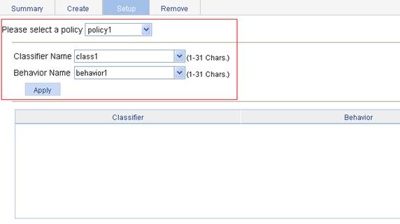
2. Click the Setup tab to enter the page for setting a policy, as shown in Figure 15.
Figure 15 The page for setting a policy
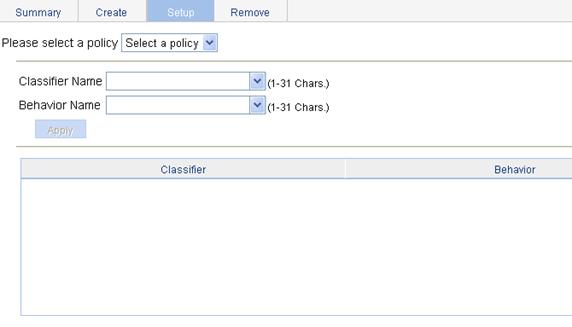
3. Configure classifier-behavior associations.
4. Click Apply.
|
Item |
Description |
|
Please select a policy |
Select an existing policy in the list. |
|
Classifier Name |
Select an existing classifier in the list. |
|
Behavior Name |
Select an existing behavior in the list. |
Applying a policy to a port
1. Select QoS > Port Policy from the navigation tree.
2. Click the Setup tab to enter the page for applying a policy to the specified ports, as shown in Figure 16.
Figure 16 The page for applying a policy to the specified ports
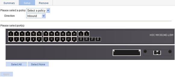
3. Select a policy and apply the policy to the specified ports.
4. Click Apply.
|
Item |
Description |
|
Please select a policy |
Select an existing policy in the list. |
|
Direction |
Set the direction in which the policy is to be applied. · Inbound: Applies the policy to the incoming packets of the specified ports. · Outbound: Applies the policy to the outgoing packets of the specified ports. |
|
Please select port(s) |
Click to select ports to which the QoS policy is to be applied on the chassis front panel. |
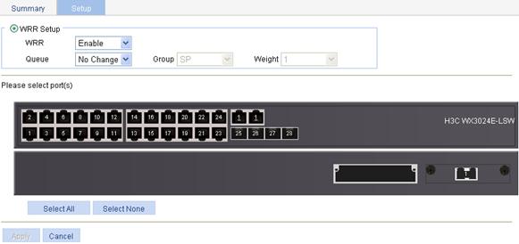
Configuring queue scheduling on a port
1. Select QoS > Queue from the navigation tree.
2. Click Setup to enter the queue scheduling configuration page, as shown in Figure 17.
Figure 17 The page for configuring queue scheduling
3. Configure queue scheduling on the specified ports.
4. Click Apply.
|
Item |
Description |
|
|
WRR Setup |
WRR |
Enable or disable the WRR queue scheduling mechanism on selected ports. Two options are available: · Enable—Enables WRR on selected ports. · Not Set—Restores the default queuing algorithm on selected ports. |
|
Queue |
Select the queue to be configured. A queue ID ranges from 0 to n-1 (n is the maximum number of queues on an interface and varies by device). |
|
|
Group |
Specify the group the current queue is to be assigned to. This list is available after you select a queue ID. The following groups are available for selection: · SP—Assigns a queue to the SP group. · 1—Assigns a queue to WRR group 1. · 2—Assigns a queue to WRR group 2. |
|
|
Weight |
Set a weight for the current queue. This option is available when group 1 or group 2 is selected. |
|
|
Please select port(s) |
Select ports to be configured with queuing on the chassis front panel. |
|
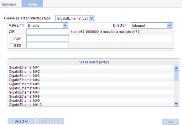
Configuring line rate on a port
1. Select QoS > Line rate from the navigation tree.
2. Select the Setup tab to enter the line rate configuration page, as shown in Figure 18.
Figure 18 The page for configuring line rate on a port
4. Click Apply.
|
Item |
Description |
|
Please select an interface type |
Select the types of interfaces to be configured with line rate. |
|
Rate Limit |
Enable or disable line rate on the specified port. |
|
Direction |
Select a direction in which the line rate is to be applied. · Inbound: Limits the rate of packets received on the specified port. · Outbound: Limits the rate of packets sent by the specified port. · Both: Limits the rate of packets sent and packets received by the specified port. |
|
CIR |
Set the committed information rate (CIR), the average traffic rate. |
|
CBS |
Set the committed burst size (CBS), number of bits that can be sent in each interval. |
|
EBS |
Set the excess burst size (EBS). EBS is available when the CBS option is selected. |
|
Please select port(s) |
Specify the ports to be configured with line rate Click the ports to be configured with line rate in the port list. You can select one or more ports. |
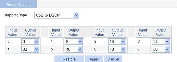
Configuring priority mapping tables
1. Select QoS > Priority Mapping from the navigation tree.
The page shown in Figure 19 appears.
Figure 19 The page for configuring priority mapping tables
2. Configure priority mapping tables.
3. Click Apply.
Table 20 Configuration items
|
Item |
Description |
|
Mapping Type |
Select the priority mapping table to be configured, which can be CoS to DSCP, CoS to Queue, DSCP to CoS, DSCP to DSCP, or DSCP to Queue. |
|
Input Priority Value |
Set the output priority value for an input priority value. |
|
Output Priority Value |
|
|
Restore |
Click Restore to display the default settings of the current priority mapping table on the page. To restore the priority mapping table to the default, click Apply. |
Configuring priority trust mode on a port
1. Select QoS > Port Priority from the navigation tree to enter the page shown in Figure 20.
Figure 20 The page for configuring port priority
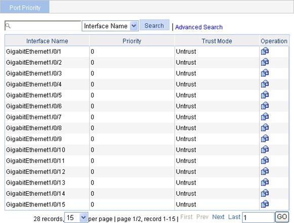
2. Click the ![]() icon
specific to a port to enter the page for configuring the priority and priority
trust mode of the port, as shown in Figure 21.
icon
specific to a port to enter the page for configuring the priority and priority
trust mode of the port, as shown in Figure 21.
Figure 21 The page for modifying port priority
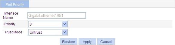
4. Click Apply.
|
Item |
Description |
|
Interface |
The interface to be configured. |
|
Priority |
Set a local precedence value for the port. |
|
Trust Mode |
Select a priority trust mode for the port, which can be · Untrust: Not trusts packet priority. · CoS: Trusts the 802.1p priority of the incoming packets. · DSCP: Trusts the DSCP value of the incoming packets. |
Configuration guidelines
When you configure ACL and QoS, follow these guidelines:
1. You cannot create a rule with, or modify a rule to have, the same permit/deny statement as an existing rule in the ACL.
2. You can only modify the existing rules of an ACL that uses the match order of config. When modifying a rule of such an ACL, you may choose to change just some of the settings, in which case the other settings remain the same.
3. When you configure line rate and traffic policing for a behavior, make sure that the ratio of CBS to CIR is more than 100:16. Otherwise, the handling for bursty traffic may be affected.
4. If the outgoing port configured for a traffic redirecting action is bound to a NAT virtual interface, packets are redirected to the L3 NAT card, which can cause traffic redirecting failure.
5. If an ACL is referenced by a QoS policy for defining traffic classification rules, packets matching the referenced ACL rule are organized as a class and the behavior defined in the QoS policy applies to the class regardless of whether the referenced ACL rule is a deny or permit clause.
6. If a QoS policy is applied in the outbound direction of a port, the QoS policy cannot influence local packets. Local packets refer to the important protocol packets that maintain the normal operation of the device. QoS must not process such packets to avoid packet drop. Commonly used local packets are: link maintenance packets, ISIS packets, OSPF packets, RIP packets, BGP packets, LDP packets, RSVP packets, and SSH packets and so on.
7. When you configure queuing for a traffic behavior:
· In a policy, a traffic behavior with EF configured cannot be associated with the default class, while a traffic behavior with WFQ configured can only be associated with the default class.
· In a policy, the total bandwidth assigned to the AF and EF classes cannot be greater than the available bandwidth of the interface to which the policy applies; the total bandwidth percentage assigned to the AF and EF classes cannot be greater than 100%.
· In the same policy, the same bandwidth unit must be used to configure bandwidth for AF classes and EF classes, either absolute bandwidth value or percent.
ACL and QoS configuration example
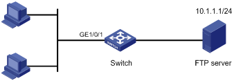
Network requirements
As shown in Figure 22, in the network, the FTP server (10.1.1.1/24) is connected to the Switch, and the clients access the FTP server through GigabitEthernet 1/0/1 of the Switch.
Configure an ACL and a QoS policy as follows to prevent the hosts from accessing the FTP server from 8:00 to 18:00 every day:
1. Create an ACL to prohibit the hosts from accessing the FTP server from 8:00 to 18:00 every day.
2. Configure a QoS policy to drop the packets matching the ACL.
3. Apply the QoS policy in the inbound direction of GigabitEthernet 1/0/1.
Configuration procedure
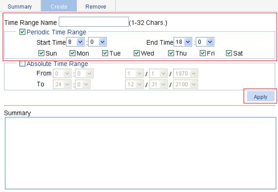
1. Define a time range to cover the time range from 8:00 to 18:00 every day.
a. Select QoS > Time Range from the navigation tree.
b. Click the Create tab.
c. On the page as shown in Figure 23, enter the time range name test-time, select the Periodic Time Range option, set the Start Time to 8:00 and the End Time to 18:00, and select the options Sun through Sat.
d. Click Apply.
Figure 23 Define a time range covering 8:00 to 18:00 every day
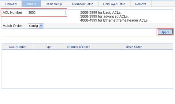
2. Create an advanced IPv4 ACL.
a. Select QoS > ACL IPv4 from the navigation tree.
b. Click the Create tab.
c. Enter the ACL number 3000.
d. Click Apply.
Figure 24 Create an advanced IPv4 ACL
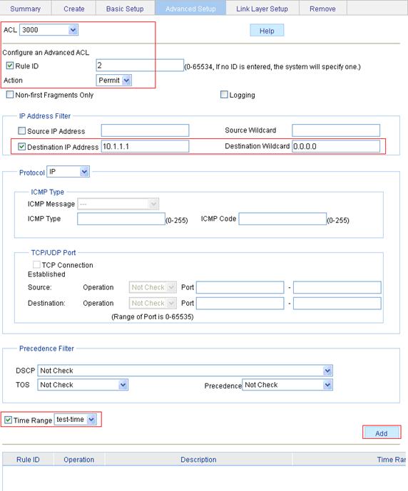
3. Define an ACL rule for traffic to the FTP server.
a. Click the Advanced Setup tab.
b. On the page as shown in Figure 25, select 3000 in the ACL list, select the Rule ID option, and enter rule ID 2.
c. Select Permit in the Action list.
d. Select the Destination IP Address option, and enter destination IP address 10.1.1.1 and destination wildcard 0.0.0.0.
e. Select test-time in the Time Range list.
f. Click Add.
Figure 25 Define an ACL rule for traffic to the FTP server
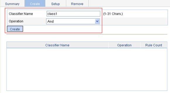
4. Create a class.
a. Select QoS > Classifier from the navigation tree.
b. Click the Create tab.
c. On the page as shown in Figure 26, enter the class name class1.
d. Click Create.
5. Define classification rules.
a. Click the Setup tab.
b. On the page as shown in Figure 27, select the class name class1 in the list, select the ACL IPv4 option, and select ACL 3000 in the following list.
Figure 27 Define classification rules
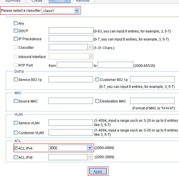
c. Click Apply.
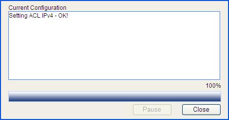
A progress dialog box appears, as shown in Figure 28.
d. Click Close on the progress dialog box when the progress dialog box prompts that the configuration succeeds.
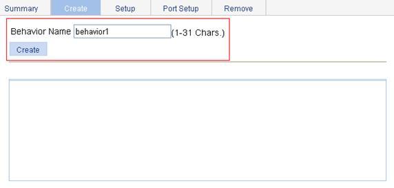
6. Create a traffic behavior.
a. Select QoS > Behavior from the navigation tree.
b. Click the Create tab.
c. On the page as shown in Figure 29, enter the behavior name behavior1.
d. Click Create.
Figure 29 Create a traffic behavior
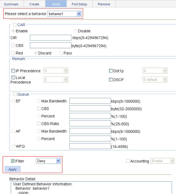
7. Configure actions for the traffic behavior.
a. Click the Setup tab.
b. On the page as shown in Figure 30, select behavior1 in the list, select the Filter option, and then select Deny in the following list.
c. Click Apply.
A progress dialog box appears.
d. Click Close when the progress dialog box prompts that the configuration succeeds.
Figure 30 Configure actions for the behavior
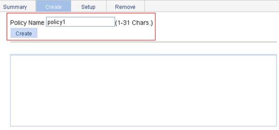
8. Create a policy.
a. Select QoS > QoS Policy from the navigation tree.
b. Click the Create tab.
c. On the page as shown in Figure 31, enter the policy name policy1.
d. Click Create.
9. Configure classifier-behavior associations for the policy.
a. Click the Setup tab.
b. On the page as shown in Figure 32, select policy1, select class1 in the Classifier Name list, and select behavior1 in the Behavior Name list.
c. Click Apply.
Figure 32 Configure classifier-behavior associations for the policy
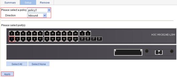
10. Apply the QoS policy in the inbound direction of GigabitEthernet 1/0/1.
a. Select QoS > Port Policy from the navigation tree.
b. Click the Setup tab.
c. Select policy1 in the Please select a policy list.
d. Select Inbound in the Direction list.
e. Select port GigabitEthernet 1/0/1.
f. Click Apply.
A configuration progress dialog box appears.
g. After the configuration is complete, click Close on the dialog box.
Figure 33 Apply the QoS policy in the inbound direction of GigabitEthernet 1/0/1