- Table of Contents
- Related Documents
-
| Title | Size | Download |
|---|---|---|
| 07-Authentication | 1.20 MB |
Contents
MAC authentication configuration
Configuring MAC authentication
Recommended configuration procedure
Configuring MAC authentication globally
Configuring MAC authentication on a port
Local MAC authentication configuration example
ACL assignment configuration example
Recommended configuration procedure
ACL assignment configuration example
Recommended configuration procedure
Configuring global settings for port security
Configuring basic port security control
Configuring secure MAC addresses
Configuring advanced port security control
Basic port security mode configuration example
Advanced port security mode configuration example
Recommended configuration procedure
Configuring authentication methods for the ISP domain
Configuring authorization methods for the ISP domain
Configuring accounting methods for the ISP domain
Recommended configuration procedure
Recommended configuration procedure for manual request
Recommended configuration procedure for automatic request
Requesting a local certificate
Retrieving and displaying a CRL
MAC authentication overview
MAC authentication controls network access by authenticating source MAC addresses on a port. It does not require client software. A user does not need to input a username and password for network access. The device initiates a MAC authentication process when it detects an unknown source MAC address on a MAC authentication enabled port. If the MAC address passes authentication, the user can access authorized network resources. If the authentication fails, the device marks the MAC address as a silent MAC address, drops the packet, and starts a quiet timer. The device drops all subsequent packets from the MAC address within the quiet time. This quiet mechanism avoids repeated authentication during a short time.
|
|
NOTE: For more information about MAC authentication, see H3C WX3000E Series Wireless Switches Switching Engine Configuration Guide. |
Configuring MAC authentication
Configuration prerequisites
· Disable port security globally.
· Create and configure an ISP domain.
· For local authentication, create local user accounts and specify the LAN access service for the accounts.
· For remote authentication, check that the device and the RADIUS server can reach each other and create user accounts on the server.
|
|
NOTE: If you are using MAC-based accounts, make sure that the username and password for each account is the same as the MAC address of the MAC authentication users. |
Recommended configuration procedure
|
Step |
Remarks |
|
Required. Enable MAC authentication globally and configure the advanced parameters. By default, MAC authentication is disabled globally. |
|
|
Required. Enable MAC authentication on a port. MAC authentication can take effect on a port only when it is enabled globally and on the port. You can configure MAC authentication on ports first. By default, MAC authentication is disabled on a port. |
Configuring MAC authentication globally
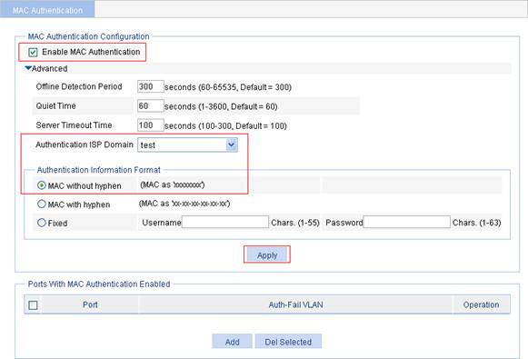
1. From the navigation tree, select Authentication > MAC Authentication.
2. In the MAC Authentication Configuration area, click Advanced.
Figure 1 MAC authentication configuration page
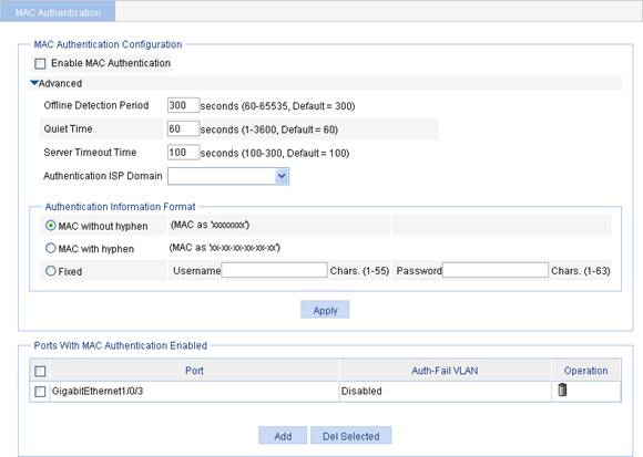
3. Configure global MAC authentication settings as described in Table 1.
4. Click Apply.
|
Item |
Description |
||
|
Enable MAC Authentication |
Select the box to enable MAC authentication globally. |
||
|
Offline Detection Period |
Set the period that the device waits for traffic from a user before it regards the user idle. |
||
|
Quiet Time |
Set the interval that the device must wait before it can perform MAC authentication for a user that has failed MAC authentication. |
||
|
Server Timeout Time |
Set the interval that the device waits for a response from a RADIUS server before it regards the RADIUS server unavailable. |
||
|
Authentication ISP Domain |
Specify the ISP domain for MAC authentication users. If no ISP domain is specified, the system default authentication domain is used for MAC authentication users. |
||
|
Authentication Information Format |
MAC without hyphen |
Configure the properties of MAC authentication user accounts. · MAC without hyphen: Uses MAC-based accounts, and excludes hyphens from the MAC address, for example, xxxxxxxxxxxx. · MAC with hyphen: Uses MAC-based accounts, and hyphenates the MAC address, for example, xx-xx-xx-xx-xx-xx. · Fixed: Uses a shared account. You must specify a username and password for the account. |
|
|
MAC with hyphen |
|||
|
Fixed |
Username |
||
|
Password |
|||
Configuring MAC authentication on a port
1. From the navigation tree, select Authentication > MAC Authentication to enter the MAC authentication configuration page, as shown in Figure 1.
The Ports With MAC Authentication Enabled area displays ports with MAC authentication enabled.
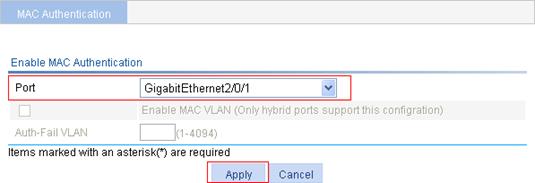
2. To enable MAC authentication on a port, click Add.
Figure 2 Configure MAC authentication on a port
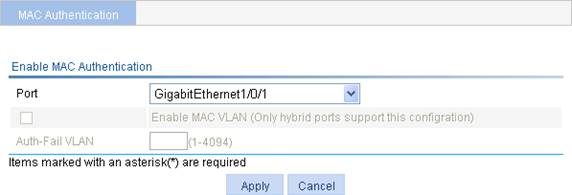
3. Configure MAC authentication for a port as described in Table 2.
4. Click Apply.
|
Item |
Description |
|
Port |
Select a port on which you want to enable MAC authentication. |
|
Enable MAC VLAN |
Select the check box to enable MAC-based VLAN on the port. NOTE: You can enable MAC authentication only on hybrid ports. |
|
Auth-Fail VLAN |
Specify a VLAN as the Auth-Fail VLAN.
· The Auth-Fail VLAN function has higher priority than the quiet function of MAC authentication. A user can access any resources. · The MAC authentication Auth-Fail VLAN function has higher priority than the block MAC action but lower priority than the shut down port action of the port intrusion protection feature. For more information about port intrusion protection, see the chapter “Port security configuration.” |
Local MAC authentication configuration example
Network requirements
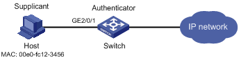
As shown in Figure 3, perform local MAC authentication on port GigabitEthernet 2/01 to control Internet access. Ensure the following:
· All users belong to the domain aabbcc.net.
· Local users use their MAC addresses as the username and password for MAC authentication. The MAC addresses are hyphenated and in lower case.
· The access device detects whether a user has gone offline every 180 seconds. When a user fails authentication, the device does not authenticate the user within 180 seconds.
Configuring a local user
Add a local user, setting the username and password as 00-e0-fc-12-34-56, the MAC address of the user, and the service type to LAN access. (Details not shown)
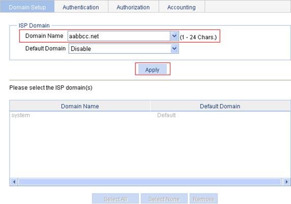
Creating an ISP domain
1. From the navigation tree, select Authentication > AAA.
The Domain Setup page appears.
2. Type aabbcc.net as the domain name, and click Apply.
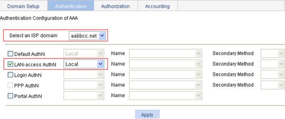
Configuring the authentication method for the ISP domain
1. On the Authentication tab, select the ISP domain aabbcc.net, select the LAN-access AuthN box, select the authentication method Local, and click Apply.
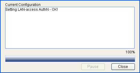
A configuration progress dialog box appears, as shown in Figure 6.
Figure 5 Configure the authentication method for the ISP domain
2. After the configuration process is complete, click Close.
Figure 6 Configuration progress dialog box
Configuring MAC authentication
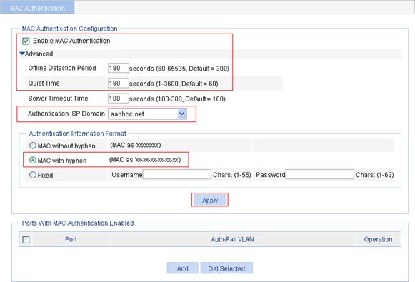
1. From the navigation tree, select Authentication > MAC Authentication.
2. Select the Enable MAC Authentication box, and click Advanced.
3. Configure advanced MAC authentication settings:
a. Set the offline detection period to 180 seconds.
b. Set the quiet time to 180 seconds.
c. Select the authentication ISP domain aabbcc.net.
d. Select MAC with hyphen as the authentication information format.
4. Click Apply.
Figure 7 Configure MAC authentication globally
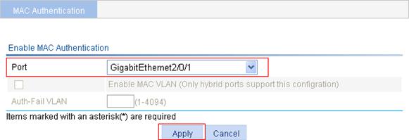
5. In the Ports With MAC Authentication Enabled area, click Add.
6. Select port GigabitEthernet2/0/1, and click Apply.
Figure 8 Enable MAC authentication for port GigabitEthernet 2/0/1
ACL assignment configuration example
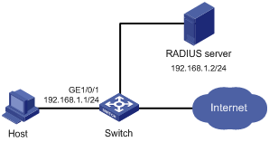
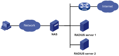
Network requirements
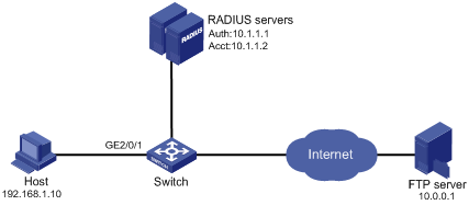
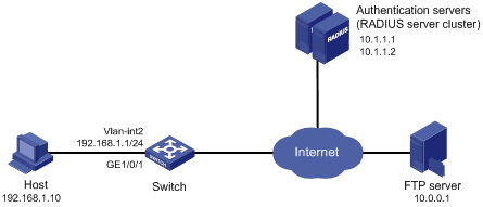
As shown in Figure 9, a host connects to port GigabitEthernet 2/0/1 on the switch and the switch uses RADIUS servers to perform authentication, authorization, and accounting. Make sure that the switch and RADIUS server can reach each other.
Perform MAC authentication on port GigabitEthernet 2/0/1 to control Internet access. Ensure that an authenticated user can access the Internet but the FTP server at 10.0.0.1.
Use MAC-based user accounts for MAC authentication users. The MAC addresses are not hyphenated.
|
|
NOTE: On the RADIUS server add a user account with the host MAC address unhyphenated as both the username and password, and specify ACL 3000 as the authorization ACL for the user account. |
Configuring RADIUS scheme system
1. From the navigation tree, select Authentication > RADIUS.
Figure 10 shows the RADIUS server configuration page.
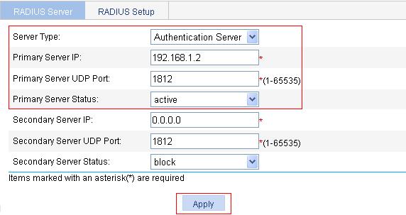
2. Configure the authentication server:
a. Select the server type Primary Authentication.
b. Type the IP address 10.1.1.1, and type the port number 1812.
c. Select active as the primary server status.
d. Click Apply.
Figure 10 Configure a RADIUS authentication server

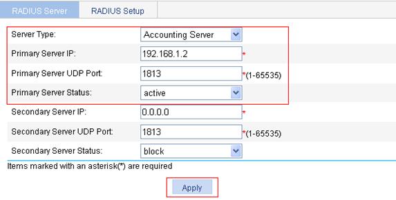
3. Configure the RADIUS accounting server:
a. Select the server type Primary Accounting.
b. Type the IP address 10.1.1.2, and type the port number 1813.
c. Select active as the primary server status.
d. Click Apply.
Figure 11 Configure a RADIUS accounting server

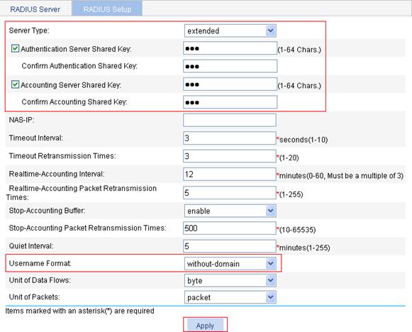
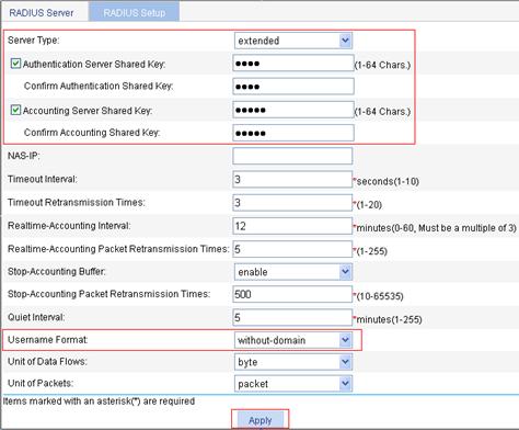
4. On the RADIUS Setup tab, configure the RADIUS scheme parameters:
a. Select the server type extended.
b. Select the Authentication Server Shared Key box and type abc in the field.
c. Type abc in the Confirm Authentication Shared Key field.
d. Select the Accounting Server Shared Key box and type abc in the field.
e. Type abc in the Confirm Accounting Shared Key field.
f. Select without-domain from the Username Format list.
g. Click Apply.
Figure 12 RADIUS scheme configuration
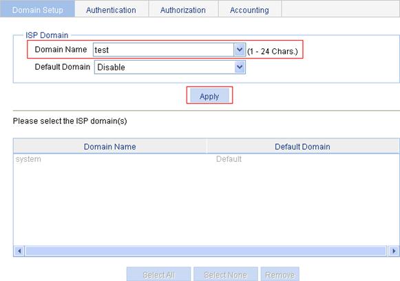
Creating an ISP domain
1. From the navigation tree, select Authentication > AAA.
Figure 13 shows the Domain Setup page.
2. Type test in the Domain Name field, and click Apply.
Figure 13 Create an ISP domain
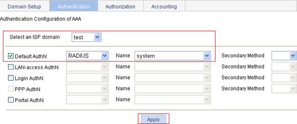
Configuring the authentication method for the ISP domain
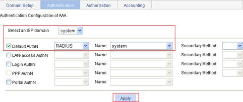
1. On the Authentication tab, select the ISP domain test, select the Default AuthN box, select the authentication method RADIUS, select the authentication scheme system from the Name list, and click Apply.
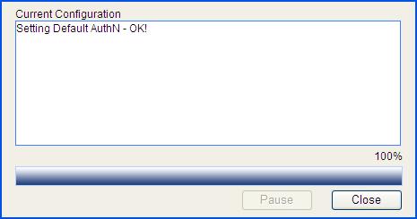
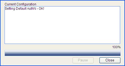
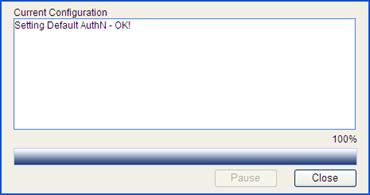
A configuration progress dialog box appears, as shown in Figure 15.
Figure 14 Configure the authentication method for the ISP domain
2. After the configuration process is complete, click Close.
Figure 15 Configuration progress dialog box
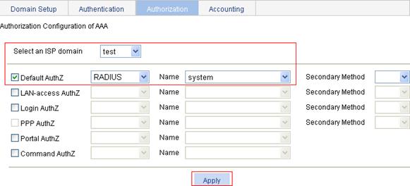
Configuring the authorization method for the ISP domain
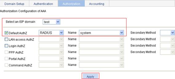
1. On the Authorization tab, select the ISP domain test, select the Default AuthZ box, select the authentication method RADIUS, select the authorization scheme system from the Name list, and click Apply.
2. After the configuration process is complete, click Close.
Figure 16 Configure the authorization method for the ISP domain
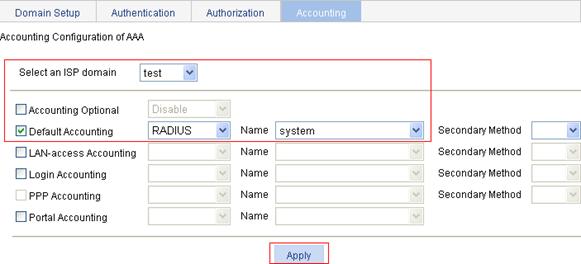
Configuring the accounting method for the ISP domain
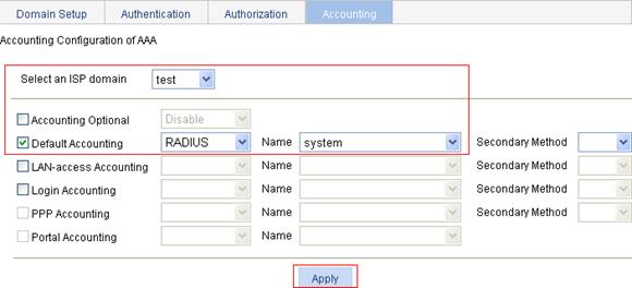
1. On the Accounting tab, select the ISP domain test, select the Default Accounting box, select the accounting method RADIUS, select the accounting scheme system from the Name list, and click Apply.
2. After the configuration process is complete, click Close.
Figure 17 Configure the accounting method for the ISP domain
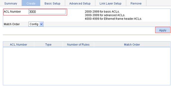
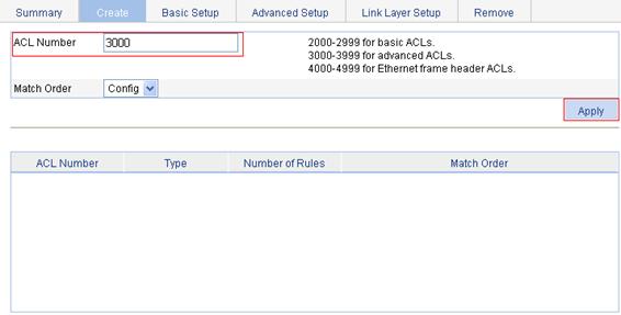
Configuring an ACL
1. From the navigation tree, select QoS > ACL IPv4.
2. Click the Add tab.
3. Type the ACL number 3000, and click Apply.
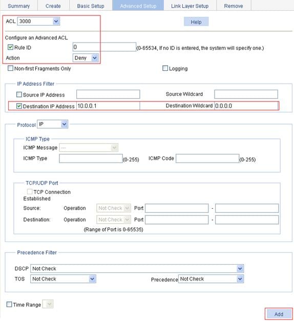
4. On the Advanced Setup tab, configure an ACL:
a. Select ACL 3000.
b. Select the Rule ID box, and type the rule ID 0.
c. Select the action Deny.
d. Select Destination IP Address box, type the destination IP address 10.0.0.1, and type the destination address wildcard 0.0.0.0.
e. Click Add.
Figure 19 Configure an ACL rule

Configuring MAC authentication
1. From the navigation tree, select Authentication > MAC Authentication.
2. Select the Enable MAC Authentication box.
3. Click Advanced.
4. Select the authentication ISP domain test, and select MAC without hyphen as the authentication information format.
5. Click Apply.
Figure 20 Configure MAC authentication globally
6. In the Ports With MAC Authentication Enabled area, click Add.
7. Select port GigabitEthernet2/0/1, and click Apply.
Figure 21 Enable MAC authentication for port GigabitEthernet 2/0/1
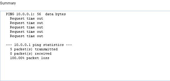
Verifying the configuration
After the host passes the authentication, ping the FTP server from the host to see whether ACL 3000 assigned by the authentication server takes effect.
C:\>ping 10.0.0.1
Pinging 10.0.0.1 with 32 bytes of data:
Request timed out.
Request timed out.
Request timed out.
Request timed out.
Ping statistics for 10.0.0.1:
Packets: Sent = 4, Received = 0, Lost = 4 (100% loss),
802.1X overview
802.1X is a port-based network access control protocol initially proposed by the IEEE 802 LAN/WAN committee for securing wireless LANs (WLANs), and it has also been widely used on Ethernet networks for access control.
802.1X controls network access by authenticating the devices connected to 802.1X-enabled LAN ports.
This chapter describes how to configure 802.1X on an H3C device. You can also configure the port security feature to perform 802.1X. Port security combines and extends 802.1X and MAC authentication. It applies to a network, a WLAN, for example, that requires different authentication methods for different users on a port. Port security is beyond the scope of this chapter. It is described in the Security Configuration Guide for the product.
802.1X architecture
802.1X operates in the client/server model. It comprises three entities: the client (the supplicant), the network access device (the authenticator), and the authentication server.
Figure 22 802.1X architecture
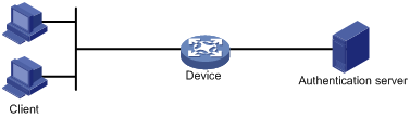
· The client is a user terminal seeking access to the LAN. It must have 802.1X software to authenticate to the network access device.
· The network access device authenticates the client to control access to the LAN. In a typical 802.1X environment, the network access device uses an authentication server to perform authentication.
· The authentication server is the entity that provides authentication services for the network access device. It authenticates 802.1X clients by using the data sent from the network access device, and returns the authentication results for the network access device to make access decisions. The authentication server is typically a Remote Authentication Dial-in User Service (RADIUS) server. In a small LAN, you can also use the network access device as the authentication server.
Access control methods
H3C implements port-based access control as defined in the 802.1X protocol, and extends the protocol to support MAC-based access control.
· With port-based access control, once an 802.1X user passes authentication on a port, any subsequent user can access the network through the port without authentication. When the authenticated user logs off, all other users are logged off.
· With MAC-based access control, each user is separately authenticated on a port. When a user logs off, no other online users are affected.
|
|
NOTE: For more information about 802.1X protocol, see H3C WX3000E Series Wireless Switches Switching Engine Configuration Guide. |
Configuring 802.1X
Configuration prerequisites
· Configure an ISP domain and AAA scheme (local or RADIUS authentication) for 802.1X users.
· If RADIUS authentication is used, create user accounts on the RADIUS server.
· If local authentication is used, create local user accounts on the access device and specify the LAN access service for the user accounts.
Recommended configuration procedure
|
Step |
Description |
|
Required. Enable 802.1X authentication globally and configure the authentication method and advanced parameters. By default, 802.1X authentication is disabled globally. |
|
|
Required. Enable 802.1X authentication on the specified ports and configure 802.1X parameters for the ports. By default, 802.1X authentication is disabled on a port. |
Configuring 802.1X globally
1. From the navigation tree, select Authentication > 802.1X.
2. Click Advanced to display the complete 802.1X configuration page.
The 802.1X Configuration area allows you to view and configure the 802.1X feature globally.
Figure 23 802.1X configuration page
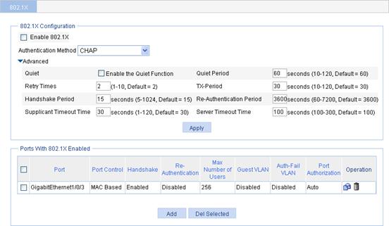
3. Configure the 802.1X feature globally as described in Table 3.
4. Click Apply.
|
Item |
Description |
|
|
Enable 802.1X |
Enable or disable 802.1X authentication globally. |
|
|
Authentication Method |
Specify the authentication method for 802.1X users. Options include CHAP, PAP, and EAP. |
|
|
Advanced |
Quiet |
Specify whether to enable the quiet timer. After an 802.1X user fails to be authenticated, the device will keep quiet for a period of time defined by Quiet Period. During the quiet period, the device will not perform 802.1X authentication on the user. |
|
Quiet Period |
Specify the value of the quiet timer. |
|
|
Retry Times |
Specify the maximum number of authentication request attempts. The network access device retransmits an authentication request if it receives no response to the request it has sent to the client within a period of time (specified by using the TX Period option or the Supplicant Timeout Time option). The network access device stops retransmitting the request, if it has made the maximum number of request transmission attempts but still received no response. |
|
|
TX-Period |
Set the username request timeout timer. |
|
|
Handshake Period |
Set the handshake timer. |
|
|
Re-Authentication Period |
Set the periodic online user re-authentication timer. |
|
|
Supplicant Timeout Time |
Set the client timeout timer. |
|
|
Server Timeout Time |
Set the server timeout timer. |
|
Configuring 802.1X on a port
1. From the navigation tree select Authentication > 802.1X to enter the 802.1X configuration page, as shown in Figure 23.
2. In the Ports With 802.1X Enabled area, click Add.
Figure 24 802.1X configuration on a port
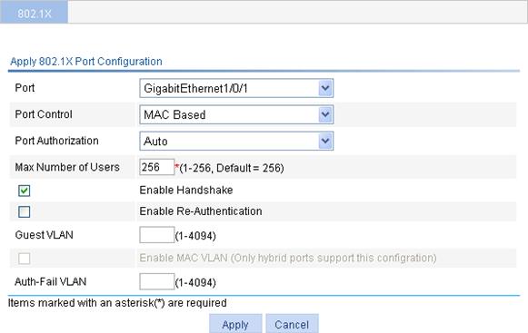
3. Configure 802.1X features on a port as described in Table 4.
4. Click Apply.
|
Item |
Description |
|
Port |
Select the port to be enabled with 802.1X authentication. Only 802.1X-disabled ports are available. |
|
Port Control |
Select the access control method for the port, which can be MAC Based or Port Based. |
|
Port Authorization |
Select the 802.1X authorization state for the port. Options include: · Auto— Places the port initially in the unauthorized state to allow only EAPOL packets to pass, and after a user passes authentication, sets the port in the authorized state to allow access to the network. You can use this option in most scenarios. · Force-Authorized— Places the port in the authorized state, enabling users on the port to access the network without authentication. · Force-Unauthorized— Places the port in the unauthorized state, denying any access requests from users on the port. |
|
Max Number of Users |
Set the maximum number of concurrent 802.1X users on the port. |
|
Enable Handshake |
Specify whether to enable the online user handshake function. |
|
Enable Re-Authentication |
Specify whether to enable periodic online user re-authentication on the port. |
|
Guest VLAN |
Specify an existing VLAN as the guest VLAN.
Assign different VLAN IDs for the voice VLAN, the default VLAN of the port, and the 802.1X guest VLAN so that the port can correctly process incoming VLAN traffic. |
|
Enable MAC VLAN |
Select the box to enable MAC-based VLAN. Required when MAC Based is selected for Port Control.
Only hybrid ports support the feature. |
|
Auth-Fail VLAN |
Specify an existing VLAN as the Auth-Fail VLAN to accommodate users that have failed 802.1X authentication.
· If a user fails both 802.1X and MAC authentication on a port that implements MAC-based access control, the user is in the 802.1X Auth-Fail VLAN. · Assign different VLAN IDs for the voice VLAN, the default VLAN of the port, and the 802.1X Auth-Fail VLAN so that the port can correctly process the incoming VLAN traffic. |
802.1X configuration example
Network requirements
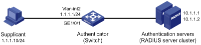
· As shown in Figure 25, perform 802.1X authentication on port GigabitEthernet 1/0/1 to control user access to the Internet, configure the access control method as MAC address based on the port, and enable periodic re-authentication of online users on the port, so that the server can periodically update the authorization information of the users.
· All users belong to default domain test. RADIUS authentication is performed. If RADIUS accounting fails, the switch gets the corresponding user offline. The RADIUS servers run CAMS or iMC.
· A server group with two RADIUS servers is connected to the switch. The IP addresses of the servers are 10.1.1.1 and 10.1.1.2 respectively. Use the former as the primary authentication/secondary accounting server, and the latter as the secondary authentication/primary accounting server.
· Set the shared key for the device to exchange packets with the authentication server as name, and that for the device to exchange packets with the accounting server as money.
· Specify the device to try up to five times at an interval of 5 seconds in transmitting a packet to the RADIUS server until it receives a response from the server, and to send real time accounting packets to the accounting server every 15 minutes.
· Specify the device to remove the domain name from the username before passing the username to the RADIUS server.
|
|
NOTE: The following configuration procedure involves RADIUS client configuration for the switch, and configurations on the RADIUS servers are omitted. For more information about RADIUS configuration, see the chapter “RADIUS configuration.” |
Configuring the IP addresses of the interfaces
Details are not shown.
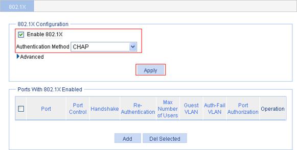
Configuring 802.1X
1. From the navigation tree, select Authentication > 802.1X.
2. Select the Enable 802.1X box, select the authentication method CHAP, and click Apply.
Figure 26 Global 802.1X configuration

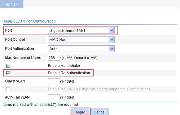
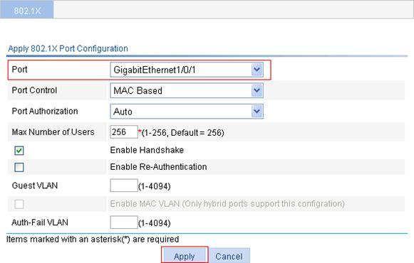
3. In the Ports With 802.1X Enabled area, click Add.
4. Select port GigabitEthernet1/0/1 from the list, select Enable Re-Authentication box, and click Apply.
Figure 27 802.1X configuration of GigabitEthernet 1/0/1
Configuring the RADIUS scheme system
1. From the navigation tree, select Authentication > RADIUS.
The RADIUS server configuration page appears.
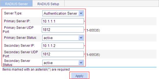
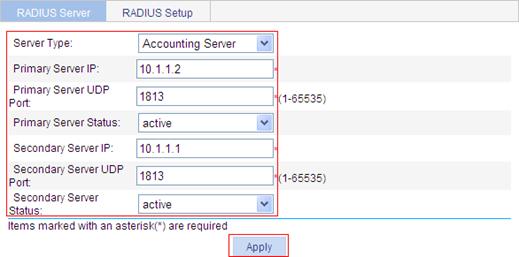
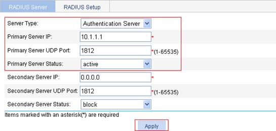
2. Configure the authentication server:
a. Select the server type Authentication Server.
b. Type the primary server IP address 10.1.1.1.
c. Select active as the primary server’s status.
d. Type the secondary server IP address 10.1.1.2.
e. Select active as the secondary server’s status.
f. Click Apply.
Figure 28 RADIUS authentication server configuration
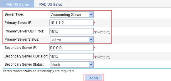
3. Configure the accounting server:
a. Select Accounting Server as the server type.
b. Type the primary server IP address 10.1.1.2.
c. Select active as the primary server’s status.
d. Type the secondary server IP address 10.1.1.1.
e. Select active as the secondary server’s status.
f. Click Apply.
Figure 29 RADIUS accounting server configuration
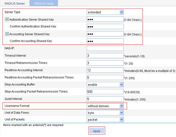
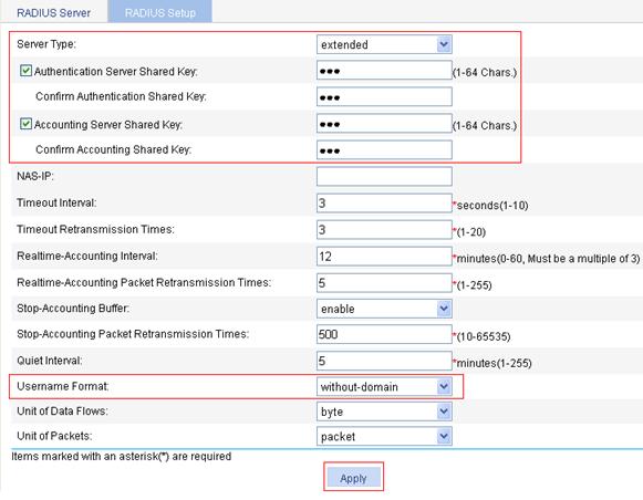
4. Click the RADIUS Setup tab, and configure the settings:
a. Select extended as the server type.
b. Select the Authentication Server Shared Key box, type abc in the field, and type abc again in the Confirm Authentication Shared Key field.
c. Select the Accounting Server Shared Key box, type abc in the field, and type abc again in the Confirm Accounting Shared Key field.
d. Select without-domain as the username format.
e. Click Apply.
Figure 30 RADIUS parameter configuration
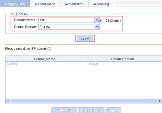
Creating an ISP domain
1. From the navigation tree, select Authentication > AAA.
The domain setup page appears.
2. Type test in the Domain Name field, select Enable from the Default Domain list, click Apply.
Figure 31 Create an ISP domain
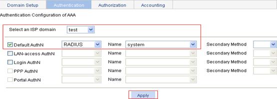
Configuring the AAA authentication method for the ISP domain
1. On the Authentication tab, select the domain name test, select the Default AuthN box, set the authentication method RADIUS, select the authentication scheme system from the Name list, and click Apply.
A configuration progress dialog box appears, as shown in Figure 33.
Figure 32 Configure the AAA authentication method for the ISP domain
2. After the configuration process is complete, click Close.
Figure 33 Configuration progress dialog box
Configuring the AAA authorization method for the ISP domain
1. On the Authorization tab, select the domain name test, select the Default AuthZ box, select authorization method RADIUS, select the authorization scheme system from the Name list, and click Apply.
2. After the configuration process is complete, click Close.
Figure 34 Configure the AAA authorization method for the ISP domain
Configuring the AAA accounting method for the ISP domain
1. On the Accounting tab, select the domain name test, select the Default Accounting box, select the accounting method RADIUS, select the accounting scheme system from the Name list, and click Apply.
2. After the configuration process is complete, click Close.
Figure 35 Configure the AAA accounting method for the ISP domain
ACL assignment configuration example
Network requirements
As shown in Figure 36, the switch and the RADIUS authentication servers (CAMS/iMC servers) work together to authenticate the host that is to access the Internet. An FTP server is on the Internet, and its IP address is 10.0.0.1.
· Configure the authentication server to assign ACL 3000.
· Enable 802.1X for port GigabitEthernet 1/0/1 and configure ACL 3000 on the switch.
After a user passes authentication, the authentication server assigns ACL 3000. At this time, ACL 3000 takes effect on GigabitEthernet 1/0/1, allowing the host to access the Internet but not the FTP server.
Configuring the IP addresses of the interfaces
Details are not shown.
Configuring the RADIUS scheme system
1. From the navigation tree, select Authentication > RADIUS.
The RADIUS Server page appears.
2. Configure the authentication server:
a. Select the server type Authentication Server.
b. Type 10.1.1.1 as the IP address of the primary authentication server.
c. Type 1812 as the UDP port of the primary authentication server.
d. Select active as the primary server status.
e. Click Apply.
Figure 37 Configure the RADIUS authentication server
3. Configure the RADIUS accounting server.
a. Select the server type Accounting Server.
b. Type 10.1.1.2 as the IP address of the primary accounting server.
c. Type 1813 as the UDP port of the primary accounting server.
d. Select active as the primary server status.
e. Click Apply.
Figure 38 Configure the RADIUS accounting server
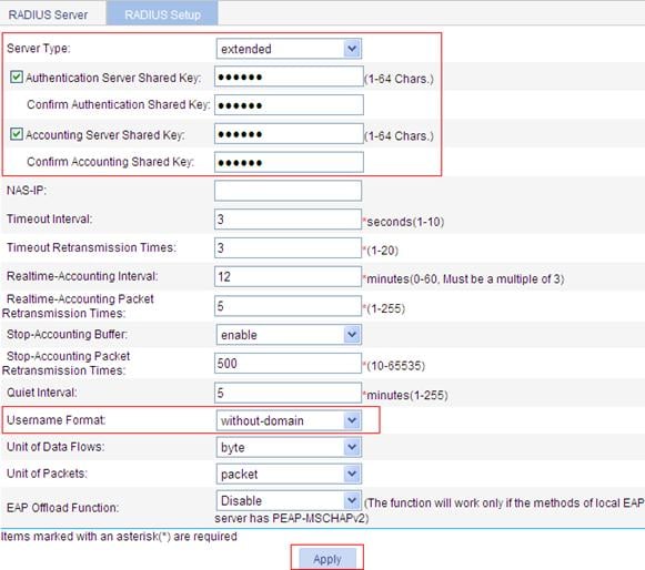
4. On the RADIUS Setup tab, configure the RADIUS parameters:
a. Select the server type extended.
b. Select the Authentication Server Shared Key box, type abc in the field, and type abc in the Confirm Authentication Shared Key field.
c. Select the Accounting Server Shared Key box, type abc in the field, and type abc in the Confirm Accounting Shared Key field.
d. Select without-domain from the Username Format list.
e. Click Apply.
Figure 39 Configure RADIUS parameters
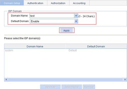
Creating an ISP domain
1. From the navigation tree, select Authentication > AAA.
The domain setup page appears.
2. Type test in the Domain Name field, select Enable from the Default Domain list, and click Apply.
Figure 40 Create an ISP domain

Configuring the AAA authentication method for the ISP domain
1. On the Authentication tab, select the domain name test, select the Default AuthN box, select the authentication method RADIUS, select the authentication scheme system from the Name list, and click Apply.
A configuration progress dialog box appears, as shown in Figure 42.
Figure 41 Configure the AAA authentication method for the ISP domain

2. After the configuration process is complete, click Close.
Figure 42 Configuration progress dialog box

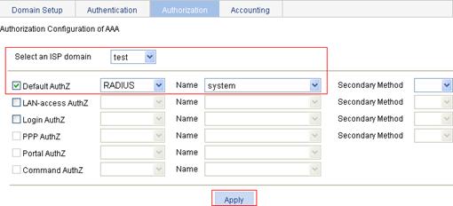
Configuring the AAA authorization method for the ISP domain
1. On the Authorization tab, select the domain name test, select the Default AuthZ box, select the authorization method RADIUS, select the authorization scheme system from the Name list, and click Apply.
2. After the configuration process is complete, click Close.
Figure 43 Configure the AAA authorization method for the ISP domain

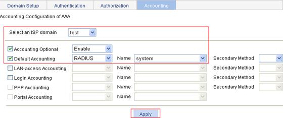
Configuring the AAA accounting method for the ISP domain
1. On the Accounting tab, select the domain name test, select the Accounting Optional box, and select Enable.
2. Select the Default Accounting box, and select the accounting method RADIUS.
3. Select the accounting scheme system from the Name list.
4. Click Apply.
5. After the configuration process is complete, click Close.
Figure 44 Configure the AAA accounting method for the ISP domain
Configuring an ACL
1. From the navigation tree, select QoS > ACL IPv4.
2. On the Add tab, type the ACL number 3000, and click Apply.
3. On the Advanced Setup tab, configure an ACL rule:
a. Select 3000 from the ACL list, select the Rule ID box, and type 0 in the field.
b. Select the action Deny.
c. In the IP Address Filter area, select the Destination IP Address box, type 10.0.0.1 in the field, and type 0.0.0.0 in the Destination Wildcard field.
d. Click Add.
Figure 46 ACL rule configuration
Configuring the 802.1X feature
1. From the navigation tree, select Authentication > 802.1X.
2. Select the Enable 802.1X box, and select the authentication method CHAP.
3. Click Apply.
Figure 47 Global 802.1X globally
4. In the Ports With 802.1X Enabled area, click Add.
5. Select GigabitEthernet1/0/1 from the Port list.
6. Click Apply.
Figure 48 802.1X configuration of GigabitEthernet 1/0/1
Verifying the configuration
After the user passes authentication and gets online, use the ping command to test whether ACL 3000 takes effect.
1. Select Network > Diagnostic Tools in the navigation tree. The ping page appears.
2. Type the destination IP address 10.0.0.1.
3. Click Start to start the ping operation.
Figure 49 shows the ping operation summary.
Figure 49 Ping operation summary
Configuration guidelines
When you configure 802.1X, follow these guidelines:
· 802.1X configuration on a specific port can take effect only after both global 802.1X and 802.1X on the specified port are enabled.
· Do not change the global 802.1X default timers unless you have determined that the changes would better the interaction process. In most cases, the default settings are sufficient.
· 802.1X is mutually exclusive with link aggregation configuration on a port.
· If EAP relay mode is used, the username format configuration on the access device does not take effect. The access device sends the authentication data from the client to the server without any modification. For more information about username format configuration, see the chapter “RADIUS configuration.”
· If the default VLAN of a port is a voice VLAN, the 802.1X function cannot take effect on the port.
Port security overview
Port security combines and extends 802.1X and MAC authentication to provide MAC-based network access control. It applies to a network, a WLAN, for example, that requires different authentication methods for different users on a port.
Port security prevents unauthorized access to the network by checking the source MAC address of inbound traffic and prevents access to unauthorized devices by checking the destination MAC address of outbound traffic.
Port security can control MAC address learning and authentication on a port to make sure that the port learns only source trusted MAC addresses.
A frame is illegal, if its source MAC address cannot be learned in a port security mode or it is from a client that has failed 802.1X or MAC authentication.
The port security feature can automatically take a pre-defined action on illegal frames. This automatic mechanism enhances network security and reduces human intervention.
|
|
NOTE: · For scenarios that require only 802.1X authentication or MAC authentication, H3C recommends you configure 802.1X authentication or MAC authentication rather than port security for simplicity. For more information about 802.1X and MAC authentication, see the chapters “802.1X configuration” and “MAC authentication configuration.” · For more information about port security, see H3C WX3000E Series Wireless Switches Switching Engine Configuration Guide. |
Configuring port security
Configuration prerequisites
· Before enabling port security, disable 802.1X and MAC authentication globally.
· Only one port security mode can be configured on a port.
Recommended configuration procedure
Configuring basic port security mode
|
Step |
Remarks |
|
Required. Enable port security globally and configure advanced parameters. Disabled by default. |
|
|
Required. Configure the basic port security mode, maximum secure MAC addresses, intrusion protection, and outbound restriction for a port. By default, port security is disabled on all ports and access to the ports is not restricted. |
|
|
Optional. Secure MAC addresses never age out or get lost if saved before the device restarts. One secure MAC address can be added to only one port in the same VLAN. You can bind a MAC address to one port in the same VLAN. Secure MAC addresses can be learned by a port working in basic port security mode, or manually configured through the Web interface. When the maximum number of secure MAC addresses is reached, no more can be added. The port allows only packets sourced from a secure MAC address to pass through. By default, no secure MAC addresses are configured. |
Configuring advanced port security mode
|
Step |
Remarks |
|
Required. Enable port security globally and configure advanced parameters. By default, port security is disabled globally. |
|
|
Required. Configure an advanced port security mode, intrusion protection, outbound restriction, and select whether to ignore the authorization information from the RADIUS server. By default, port security is disabled on all ports and access to the ports is not restricted. |
|
|
Optional. This setting is available only with the 802.1X MAC Based Or OUI mode. You can configure 16 permitted OUI values at most, however, a port in 802.1X MAC Based Or OUI mode allows only one 802.1X user and one user whose MAC address contains a specified OUI to pass authentication at the same time. By default, no OUI values are configured. |
Configuring global settings for port security
1. From the navigation tree, select Authentication > Port Security.
The Port Security Configuration area displays the global port security configuration and allows you to make modifications.
Figure 50 Port security configuration page
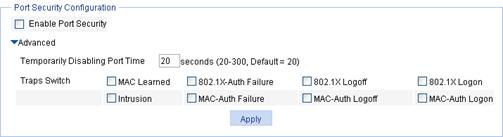
2. Click Advanced to expand the advanced configuration area.
Figure 51 Port security configuration
|
Item |
Description |
|
|
Enable Port Security |
Select the box to enable the port security feature globally. Disabled by default. |
|
|
Advanced |
Temporarily Disabling Port Time |
Specify the time length for how long the port is disabled temporarily upon receiving illegal frames. |
|
Traps Switch |
Select one or more events to trigger trap sending. Available events include: · MAC Learned · 802.1X-Auth Failure · 8021X Logoff · 802.1X Logon · Intrusion · MAC-Auth Failure · MAC-Auth Logoff MAC-Auth Logon |
|
Configuring basic port security control
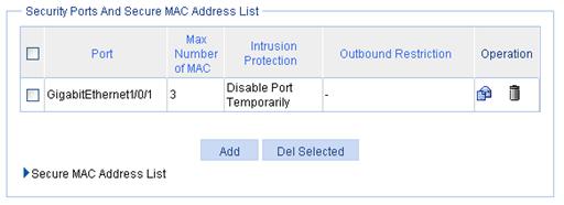
1. From the navigation tree, select Authentication > Port Security to enter the page as shown in Figure 50.
The Security Ports And Secure MAC Address List area displays the port security control settings.
Figure 52 Security Ports And Secure MAC Address List area
2. Click Add to enter the page for creating a port security control.
Figure 53 Configure basic port security control
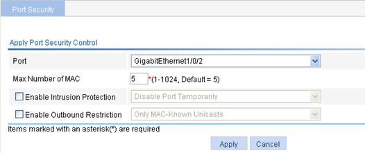
3. Configure port security control as described in Table 6.
4. Click Apply.
|
Item |
Description |
|
Port |
Select the port where you want to configure port security. By default, port security is disabled on all ports and access to the ports is not restricted. |
|
Max Number of MAC |
Specify the maximum number of secure MAC addresses that can be set on the port. The number of authenticated users on the port cannot exceed the specified upper limit. By setting the maximum number of secure MAC addresses allowed on a port, you can implement the following control: · Control the maximum number of users allowed to access the network through the port. · Control the number of secure MAC addresses that can be added with port security. This configuration is independent of the maximum number of MAC addresses that can be learned by the port in MAC address management. |
|
Enable Intrusion Protection |
Select the option to enable intrusion protection, and select the action to take on illegal frames. Available actions include: · Disable Port Temporarily—Disables the port for a period of time. The period can be configured in the global settings. For more information, see “Configuring global settings for port security.” · Disable Port Permanently—The port will not come up unless being brought up manually. Block MAC—Adds the source MAC addresses of illegal frames to the blocked MAC addresses list and discards the frames. All subsequent frames sourced from a blocked MAC address will be dropped. A blocked MAC address is restored to normal state after being blocked for three minutes. The interval is fixed and cannot be changed. |
|
Enable Outbound Restriction |
Select the option to enable outbound traffic control, and select the control method. Available control methods include: · Only MAC-Known Unicasts—Allows only unicast frames with their destination MAC addresses being authenticated to pass through. · Only Broadcasts and MAC-Known Unicasts—Allows only broadcast and unicast packets with their destination MAC addresses being authenticated to pass through. Only Broadcasts, Multicasts, and MAC-Known Unicasts—Allows only broadcast, multicast, and known unicast packets with their destination MAC addresses being authenticated to pass through. |
Configuring secure MAC addresses
1. From the navigation tree, select Authentication > Port Security to enter the page as shown in Figure 50.
2. In the Security Ports And Secure MAC Address List area, click Secure MAC Address List.
3. The secure MAC address configuration area displays the secure MAC addresses that have been learned or configured.
Figure 54 Secure MAC address list

4. Click Add.
Figure 55 Secure MAC address configuration page

5. Configure secure MAC address entries as described in Table 7.
6. Click Apply.
|
Item |
Description |
|
Port |
Select the port for which the secure MAC address table is configured. |
|
Secure MAC Address |
Type the MAC address that you want to configure as a secure MAC address. |
|
VLAN ID |
Type the ID of the VLAN in which the secure MAC address is configured. The VLAN must be created on the selected port. |
Configuring advanced port security control
1. From the navigation tree, select Authentication > Port Security to enter the page as shown in Figure 50.
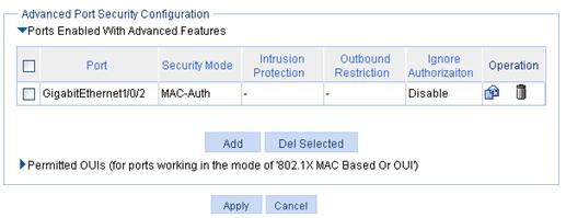
2. In the Advanced Port Security Configuration area, click Ports Enabled With Advanced Features to expand the area.
Figure 56 Ports Enabled With Advanced Features area
3. Click Add.
Figure 57 Configure advanced port security control
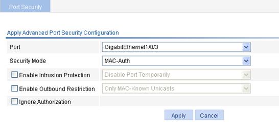
4. Configure advanced port security control as described in Table 8.
5. Click Apply.
|
Item |
Description |
|
Port |
Select the port where you want to configure port security. By default, port security is disabled on all ports and access to the ports is not restricted. |
|
Security Mode |
Select a port security mode. For more information about advanced security modes, see H3C WX3000E Series Wireless Switches Switching Engine Configuration Guide. |
|
Enable Intrusion Protection |
Select the option to enable intrusion protection, and select the action to take upon detection of illegal frames. Available actions include: · Disable Port Temporarily—Disables the port for a period of time. The period can be configured in the global settings. For more information, see “Configuring global settings for port security.” · Disable Port Permanently—The port will not come up unless being brought up manually. Block MAC—Adds the source MAC addresses of illegal frames to the blocked MAC addresses list and discards the frames. All subsequent frames sourced from a blocked source MAC address will be dropped. A blocked MAC address is restored to normal state after being blocked for three minutes. The interval is fixed and cannot be changed. |
|
Enable Outbound Restriction |
Select the option to enable the outbound traffic control and select the control method. Available control methods include: · Only MAC-Known Unicasts—Allows only unicasts frames with their destination MAC addresses being authenticated to pass through. · Only Broadcasts and MAC-Known Unicasts—Allows only broadcast and unicasts packets with their destination MAC addresses being authenticated to pass through. · Only Broadcasts, Multicasts, and MAC-Known Unicasts—Allows only broadcast, multicast, and unicasts packets with their destination MAC addresses being authenticated to pass through. |
|
Ignore Authorization |
Select the option to configure the port to ignore the authorization information from the RADIUS server. The authorization information is delivered by the RADIUS server to the device after an 802.1X user or MAC authenticated user passes RADIUS authentication. |
Configuring permitted OUI
1. From the navigation tree, select Authentication > Port Security to enter the page as shown in Figure 50.
2. In the Advanced Port Security Configuration area, click Permitted OUIs to expand the area.
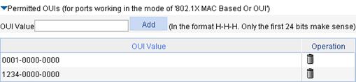
3. Type the 48-bit MAC address in the format of H-H-H in the OUI Value field, and click Add.
The system automatically saves the first 24 bits as an OUI value.
Basic port security mode configuration example
Network requirements
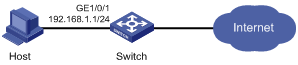
As shown in Figure 59, configure port GigabitEthernet 1/0/1 of the switch:
· Allow up to three users to access the port without authentication and permit the port to learn the MAC addresses of the users as secure MAC addresses.
· After the number of secure MAC addresses reaches three, the port stops learning MAC addresses. If an unknown MAC address frame arrives, intrusion protection is triggered and the port is disabled and stays silence for 30 seconds.
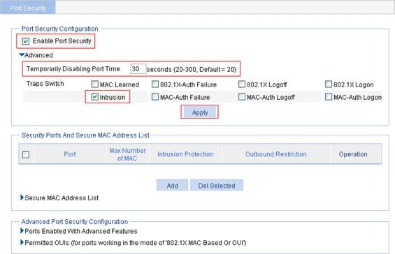
Configuring global port security settings
1. From the navigation tree, select Authentication > Port Security.
2. In the Port Security Configuration area, configure global port security settings:
a. Select the Enable Port Security box.
b. Click Advanced.
c. Specify the system to disable the port temporarily for 30 seconds.
d. Select the Intrusion box.
e. Click Apply.
Figure 60 Configure port security
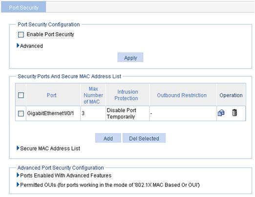
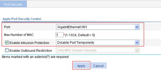
Configuring the basic port security feature
1. In the Security Ports And Secure MAC Address List area, click Add.
2. Select GigabitEthernet1/0/1.
3. Type 3 for the maximum number of MAC addresses.
4. Select the Enable Intrusion Protection box and select Disable Port Temporarily then from the list.
5. Click Apply.
Figure 61 Apply the port security feature
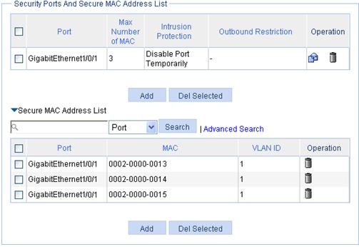
Verifying the configuration
After the configuration is completed, you can display the secure MAC address entries learned and manually configured on port GigabitEthernet 1/0/1. As the maximum number of secure MAC is configured as 3, so up to 3 MAC addresses can be learned and added as secure MAC addresses, as shown in Figure 62.
Figure 62 Secure MAC address list
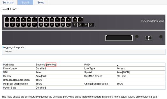
When the maximum number of MAC addresses is reached, intrusion protection is triggered. Select Device > Port Management in the navigation tree and then select the Detail tab. On the page, click the target port, GigabitEthernet 1/0/1 in this example in the chassis front panel to view details. Figure 63 shows that the port is inactive.
Figure 63 Port management—port inactive
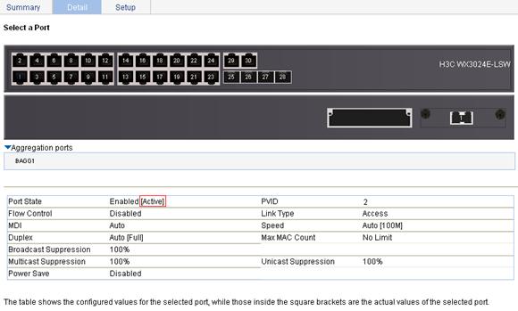
Re-select GigabitEthernet 1/0/1 to refresh its data 30 seconds later. Figure 64 shows that the port state changes to active.
Figure 64 Port management—port active
If you remove MAC addresses from the secure MAC address list, the port can continue to learn MAC addresses.
Advanced port security mode configuration example
Network requirements
As shown in Figure 65, a client is connected to the switch through port GigabitEthernet 1/0/1. The switch authenticates the client with a RADIUS server. If the authentication succeeds, the client is authorized to access the Internet.
· The RADIUS server at 192.168.1.2 functions as the primary authentication server and the secondary accounting server, and the RADIUS server at 192.168.1.3 functions as the secondary authentication server and the primary accounting server. The shared key for authentication is name, and that for accounting is money.
· All users use the default authentication, authorization, and accounting methods of ISP domain system.
· The switch sends user names without domain names to the RADIUS server.
Configure port GigabitEthernet 1/0/1 of the switch to:
· Allow only one 802.1X user to be authenticated.
· Allow up to three OUI values to be configured and allow one terminal that uses any of the OUI values to access the port in addition to an 802.1X user.
|
|
NOTE: Configurations on the host and RADIUS servers are omitted. |
Configuring a RADIUS scheme named system
1. Select Authentication > RADIUS.
2. Configure a RADIUS authentication server:
a. Select the server type Authentication Server.
b. Type 192.168.1.2 as the primary server IP address.
c. Type 1812 as the primary server UDP port.
d. Select active for the primary server status.
e. Click Apply.
Figure 66 Configure the RADIUS authentication server
3. Configure a RADIUS accounting server:
a. Select Accounting Server as the server type.
b. Type 192.168.1.2 as the primary server IP.
c. Type 1813 as the primary server UDP port.
d. Select active as the primary server status.
e. Click Apply.
Figure 67 Configure the RADIUS accounting server
4. On the RADIUS Setup, configure the RADIUS scheme:
a. Select the server type extended.
b. Select the Authentication Server Shared Key box, type name in the field, and type name in the Confirm Authentication Shared Key field.
c. Select the Accounting Server Shared Key box, type money in the field, and type money in the Confirm Accounting Shared Key field.
d. Select without-domain from the Username Format list.
e. Click Apply.
Figure 68 Configure RADIUS parameters
Configuring the AAA authentication method for the ISP domain
1. From the navigation tree, select Authentication > AAA,
2. Click the Authentication tab, select the ISP domain system, select the Default AuthN box, select the authentication method RADIUS from the list, select system from the Name list, and click Apply.
A dialog box appears, displaying the configuration progress, as shown in Figure 70.
Figure 69 Configure AAA authentication
3. When the configuration process is complete, click Close.
Figure 70 Configuration progress dialog box
Configuring the AAA authorization method for the ISP domain
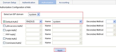
1. On the Authorization tab, select the ISP domain system, select the Default AuthZ box, select the authorization method RADIUS, select the authorization scheme system from the Name, and click Apply.
2. When the configuration process is complete, click Close.
Figure 71 Configure the AAA authorization method
Configuring the AAA accounting method for the ISP domain
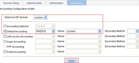
1. On the Accounting tab, select the ISP domain system, select the Default Accounting box, select accounting method RADIUS from the list, select the accounting scheme system from the Name list, and click Apply.
2. When the configuration process is complete, click Close.
Figure 72 Configure the AAA accounting method
Configuring port security
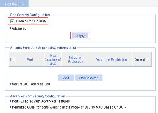
1. From the navigation tree, select Authentication > Port Security.
2. Select the Enable Port Security box, and click Apply.
Figure 73 Configure global port security settings
3. In the Advanced Port Security Configuration area, click Ports Enabled With Advanced Features, and click Add.
Figure 74 Configure advanced port security control settings on GigabitEthernet 1/0/1
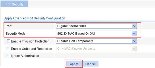
4. Select GigabitEthernet1/0/1, select the security mode 802.1X MAC Based Or OUI, and click Apply.
5. In the Advanced Port Security Configuration area, click Permitted OUIs.
Figure 75 Configure permitted OUI values
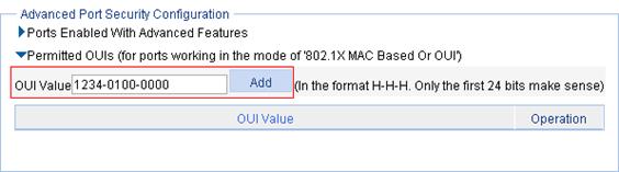
6. Type 1234-0100-0000 in the OUI Value field, and click Add.
7. Repeat the previous two steps to add the OUI values of the MAC addresses 1234-0200-0000 and 1234-0300-0000.
AAA configuration
The web interface supports configuring ISP domains and configuring authentication, authorization, and accounting methods for the ISP domains.
AAA overview
Authentication, Authorization, and Accounting (AAA) provides a uniform framework for implementing network access management. It can provide the following security functions:
· Authentication—Identifies users and determines whether a user is valid.
· Authorization—Grants different users different rights and controls their access to resources and services. For example, a user who has successfully logged in to the device can be granted read and print permissions to the files on the device.
· Accounting—Records all network service usage information of users, including the service type, start time, and traffic. The accounting function not only provides the information required for charging, but also allows for network security surveillance.
AAA usually uses a client/server model. The client runs on the network access server (NAS), which is also referred to as the access device. The server maintains user information centrally. In an AAA network, a NAS is a server for users but a client for the AAA servers.
AAA can be implemented through multiple protocols. The device supports using RADIUS, the most commonly used protocol in practice. For more information about RADIUS, see the chapter “RADIUS configuration.”
|
|
NOTE: For more information about AAA and ISP domain, see H3C WX3000E Series Wireless Switches Switching Engine Configuration Guide. |
Configuring AAA
Configuration prerequisites
To deploy local authentication, configure local users on the access device as described in the chapter “User configuration.”
To deploy remote authentication, authorization, or accounting, create the RADIUS schemes to be referenced as described in the chapter “RADIUS configuration.”
Recommended configuration procedure
|
Step |
Remarks |
|
|
Optional. Create ISP domains and specify one of them as the default ISP domain. By default, there is an ISP domain named system, which is the default ISP domain. |
||
|
Optional. Configure authentication methods for various types of users. By default, all types of users use local authentication. |
AAA user types include LAN access users (such as 802.1X authentication users and MAC authentication users), login users (such as SSH, Telnet, FTP, terminal access users), PPP users, and Command users. |
|
|
Optional. Specify the authorization methods for various types of users. |
||
|
Required. Specify the accounting methods for various types of users. By default, all types of users use local accounting. |
||
Configuring an ISP domain
1. Select Authentication > AAA from the navigation tree.
The Domain Setup page appears.
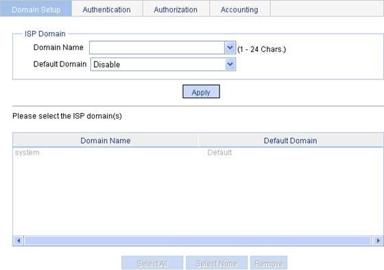
2. Configure an ISP domain as described in Table 9.
3. Click Apply.
|
Item |
Description |
|
Domain Name |
Enter the ISP domain name, which is for identifying the domain. You can enter a new domain name to create a domain, or specify an existing domain to change its status (whether it is the default domain). |
|
Default Domain |
Specify whether to use the ISP domain as the default domain. Options include: · Enable—Uses the domain as the default domain. · Disable—Uses the domain as a non-default domain. There can only be one default domain at a time. If you specify a second domain as the default domain, the original default domain will become a non-default domain. |
Configuring authentication methods for the ISP domain
1. Select Authentication > AAA from the navigation tree.
2. Click the Authentication tab to enter the authentication method configuration page.
Figure 78 Authentication method configuration page
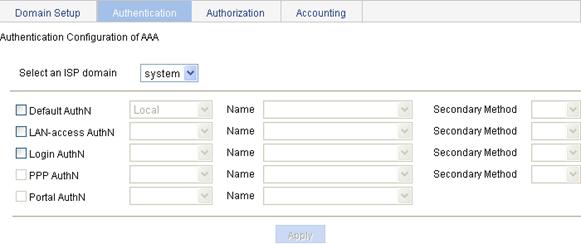
3. Configure authentication methods for different types of users in the domain, as described in Table 10.
4. Click Apply.
|
Item |
Description |
|
Select an ISP domain |
Select the ISP domain for which you want to specify authentication methods. |
|
Default AuthN |
Configure the default authentication method and secondary authentication method for all types of users. Options include: · HWTACACS—Performs HWTACACS authentication. You need to specify the HWTACACS scheme to be used. · Local—Performs local authentication. · None—All users are trusted and no authentication is performed. Generally, do not use this mode. · RADIUS—Performs RADIUS authentication. You need to specify the RADIUS scheme to be used. · Not Set—Restore the default, that is, local authentication. |
|
Name |
|
|
Secondary Method |
|
|
LAN-access AuthN |
Configure the authentication method and secondary authentication method for LAN access users. Options include: · Local—Performs local authentication. · None—All users are trusted and no authentication is performed. Generally, do not use this mode. · RADIUS—Performs RADIUS authentication. You need to specify the RADIUS scheme to be used. · Not Set—Uses the default authentication methods. |
|
Name |
|
|
Secondary Method |
|
|
Login AuthN |
Configure the authentication method and secondary authentication method for login users. Options include: · HWTACACS—Performs HWTACACS authentication. You need to specify the HWTACACS scheme to be used. · Local—Performs local authentication. · None—All users are trusted and no authentication is performed. Generally, do not use this mode. · RADIUS—Performs RADIUS authentication. You need to specify the RADIUS scheme to be used. · Not Set—Uses the default authentication methods. |
|
Name |
|
|
Secondary Method |
|
|
PPP AuthN |
Configure the authentication method and secondary authentication method for PPP users. Options include: · HWTACACS—Performs HWTACACS authentication. You need to specify the HWTACACS scheme to be used. · Local—Performs local authentication. · None—All users are trusted and no authentication is performed. Generally, do not use this mode. · RADIUS—Performs RADIUS authentication. You need to specify the RADIUS scheme to be used. · Not Set—Uses the default authentication methods. |
|
Name |
|
|
Secondary Method |
Configuring authorization methods for the ISP domain
1. Select Authentication > AAA from the navigation tree.
2. Click the Authorization tab to enter the authorization method configuration page.
Figure 79 Authorization method configuration page
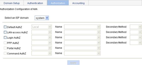
3. Configure authorization methods for different types of users in the domain, as described in Table 11.
4. Click Apply.
|
Item |
Description |
|
Select an ISP domain |
Select the ISP domain for which you want to specify authentication methods. |
|
Default AuthZ |
Configure the default authorization method and secondary authorization method for all types of users. Options include: · HWTACACS—Performs HWTACACS authorization. You need to specify the HWTACACS scheme to be used. · Local—Performs local authorization. · None—All users are trusted and authorized. A user gets the default rights of the system. · RADIUS—Performs RADIUS authorization. You need to specify the RADIUS scheme to be used. · Not Set—Restore the default, that is, local authorization. |
|
Name |
|
|
Secondary Method |
|
|
LAN-access AuthZ |
Configure the authorization method and secondary authorization method for LAN access users. Options include: · Local—Performs local authorization. · None—All users are trusted and authorized. A user gets the default rights of the system. · RADIUS—Performs RADIUS authorization. You need to specify the RADIUS scheme to be used. · Not Set—Uses the default authorization methods. |
|
Name |
|
|
Secondary Method |
|
|
Login AuthZ |
Configure the authorization method and secondary authorization method for login users. Options include: · HWTACACS—Performs HWTACACS authorization. You need to specify the HWTACACS scheme to be used. · Local—Performs local authorization. · None—All users are trusted and authorized. A user gets the default rights of the system. · RADIUS—Performs RADIUS authorization. You need to specify the RADIUS scheme to be used. · Not Set—Uses the default authorization methods. |
|
Name |
|
|
Secondary Method |
|
|
PPP AuthZ |
Configure the authorization method and secondary authorization method for PPP users. Options include: · HWTACACS—Performs HWTACACS authorization. You need to specify the HWTACACS scheme to be used. · Local—Performs local authorization. · None—All users are trusted and authorized. A user gets the default rights of the system. · RADIUS—Performs RADIUS authorization. You need to specify the RADIUS scheme to be used. · Not Set—Uses the default authorization methods. |
|
Name |
|
|
Secondary Method |
|
|
Command AuthZ |
Configure the authorization method for command users. Options include: · HWTACACS—Performs HWTACACS authorization. You need to specify the HWTACACS scheme to be used. · Not Set—Uses the default authorization methods. |
|
Name |
Configuring accounting methods for the ISP domain
1. Select Authentication > AAA from the navigation tree.
2. Click the Accounting tab to enter the accounting method configuration page.
Figure 80 Accounting method configuration page
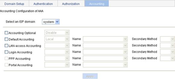
3. Configure accounting methods for different types of users in the domain, as described in Table 12.
4. Click Apply.
|
Item |
Description |
|
Select an ISP domain |
Select the ISP domain for which you want to specify authentication methods. |
|
Accounting Optional |
Specify whether to enable the accounting optional feature. With the feature enabled, a user that will be disconnected otherwise can use the network resources even when there is no accounting server available or communication with the current accounting server fails. If accounting for such a user fails, the device will not send real-time accounting updates for the user any more. |
|
Default Accounting |
Configure the default accounting method and secondary accounting method for all types of users. Options include: · HWTACACS—Performs HWTACACS accounting. You need to specify the HWTACACS scheme to be used. · Local—Performs local accounting. · None—Performs no accounting. · RADIUS—Performs RADIUS accounting. You need to specify the RADIUS scheme to be used. · Not Set—Restore the default, that is, local accounting. |
|
Name |
|
|
Secondary Method |
|
|
LAN-access Accounting |
Configure the accounting method and secondary accounting method for LAN access users. Options include: · Local—Performs local accounting. · None—Performs no accounting. · RADIUS—Performs RADIUS accounting. You need to specify the RADIUS scheme to be used. · Not Set—Uses the default accounting methods. |
|
Name |
|
|
Secondary Method |
|
|
Login Accounting |
Configure the accounting method and secondary accounting method for login users. Options include: · HWTACACS—Performs HWTACACS accounting. You need to specify the HWTACACS scheme to be used. · Local—Performs local accounting. · None—Performs no accounting. · RADIUS—Performs RADIUS accounting. You need to specify the RADIUS scheme to be used. · Not Set—Uses the default accounting methods. |
|
Name |
|
|
Secondary Method |
|
|
PPP Accounting |
Configure the accounting method and secondary accounting method for PPP users. Options include: · HWTACACS—Performs HWTACACS accounting. You need to specify the HWTACACS scheme to be used. · Local—Performs local accounting. · None—Performs no accounting. · RADIUS—Performs RADIUS accounting. You need to specify the RADIUS scheme to be used. · Not Set—Uses the default accounting methods. |
|
Name |
|
|
Secondary Method |
AAA configuration example
Network requirements
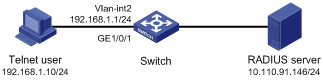
As shown in Figure 81, configure the switch to perform local authentication, authorization, and accounting for Telnet users.
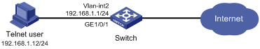
Configuration procedure
|
|
NOTE: Enable the Telnet server function, and configure the switch to use AAA for Telnet users. The configuration steps are not shown. |
1. Assign IP addresses to the interfaces. (Details not shown)
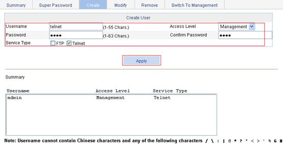
2. Configure a local user:
a. Select Device > Users from the navigation tree.
b. Click the Create tab to enter the local user configuration page.
c. Enter the username telnet, select the access level Management, enter the password abcd, and select the service type Telnet Service.
d. Click Apply.
Figure 82 Configure a local user
3. Configure ISP domain test:
a. Select Authentication > AAA from the navigation tree.
The domain configuration page appears.
b. Enter the domain name test.
c. Click Apply.
Figure 83 Configure ISP domain test

4. Configure the ISP domain to use local authentication:
a. Select Authentication > AAA from the navigation tree.
b. Click the Authentication tab to enter the AAA authentication configuration page.
c. Select the domain test, select the Login AuthN box, and select the authentication method Local.
Figure 84 Configure the ISP domain to use local authentication
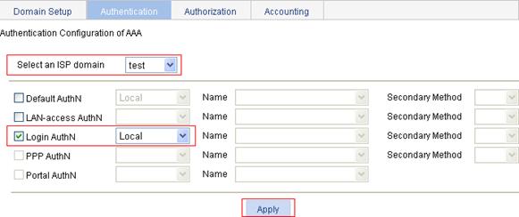
d. Click Apply.
A configuration progress dialog box appears.
e. After the configuration process is complete, click Close.
Figure 85 Configuration progress dialog box

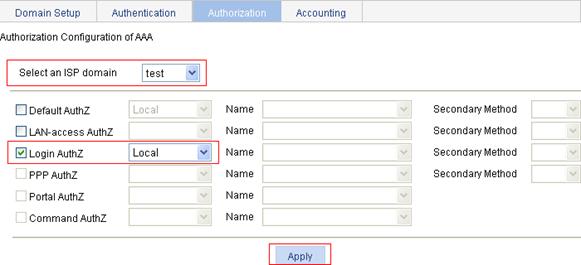
5. Configure the ISP domain to use local authorization:
a. Select Authentication > AAA from the navigation tree.
b. Click the Authorization tab to enter the AAA authorization configuration page.
c. Select the domain test, select the Login AuthZ box, and select the authorization method Local.
d. Click Apply.
A configuration progress dialog box appears.
e. After the configuration progress is complete, click Close.
Figure 86 Configure the ISP domain to use local authorization
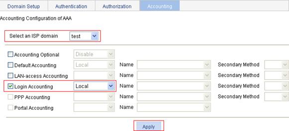
6. Configure the ISP domain to use local accounting:
a. Select Authentication > AAA from the navigation tree.
b. Click the Accounting tab to enter the AAA accounting configuration page.
c. Select the domain test, select the Login Accounting box, and select the accounting method Local.
d. Click Apply.
A configuration progress dialog box appears.
e. After the configuration progress is complete, click Close.
Figure 87 Configure the ISP domain to use local accounting
7. Verify the configuration
Telnet to the switch and enter the username telnet@test and password abcd. You should be serviced as a user in domain test.
RADIUS overview
The Remote Authentication Dial-In User Service (RADIUS) protocol implements Authentication, Authorization, and Accounting (AAA).
RADIUS uses the client/server model. It can protect networks against unauthorized access and is often used in network environments where both high security and remote user access are required. RADIUS defines the packet format and message transfer mechanism, and uses UDP as the transport layer protocol for encapsulating RADIUS packets. It uses UDP port 1812 for authentication and UDP port 1813 for accounting.
RADIUS was originally designed for dial-in user access. With the addition of new access methods, RADIUS has been extended to support additional access methods, for example, Ethernet and ADSL. RADIUS provides access authentication and authorization services, and its accounting function collects and records network resource usage information.
|
|
NOTE: For more information about RADIUS and AAA, see H3C WX3000E Series Wireless Switches Switching Engine Configuration Guide. |
Configuring RADIUS
|
|
NOTE: · The RADIUS scheme configured through the Web interface is named system. · If there is no RADIUS scheme named system in the system, when you select Authentication > RADIUS to enter the RADIUS module, a scheme named system will be created automatically. |
Recommended configuration procedure
|
Step |
Description |
|
|
1. Configuring RADIUS authentication servers |
Required Configure the information related to the primary and secondary RADIUS authentication servers. By default, no RADIUS authentication server is configured. |
|
|
2. Configuring RADIUS accounting servers |
Optional Configure the information related to the primary and secondary RADIUS accounting servers. By default, no RADIUS accounting server is configured. |
|
|
Required Configure the parameters that are necessary for information exchange between the device and RADIUS servers. |
||
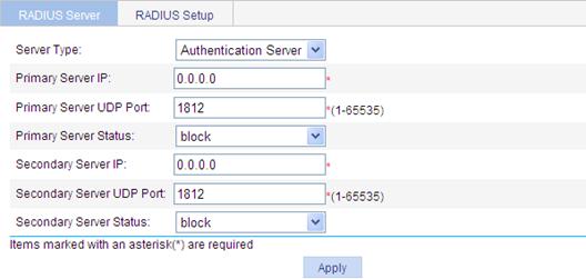
Configuring RADIUS servers
1. Select Authentication > RADIUS from the navigation tree to enter the RADIUS server configuration page.
Figure 88 RADIUS server configuration
2. Configure RADIUS servers as described in Table 13.
3. Click Apply.
Table 13 Configuration items
|
Item |
Description |
|
Server Type |
Specify the type of the server to be configured, which can be Authentication Server and Accounting Sever. |
|
Primary Server IP |
Specify the IP address of the primary server. If no primary server is specified, the box displays 0.0.0.0. To remove the previously configured primary server, enter 0.0.0.0 in the box. The specified IP address of the primary server cannot be the same as that of the secondary server. |
|
Primary Server UDP Port |
Specify the UDP port of the primary server. If the IP address of the primary server is not specified or the specified IP address is to be removed, the port number is 1812 for authentication or 1813 for accounting. |
|
Primary Server Status |
Set the status of the primary server, including: · active: The server is working normally. · blocked: The server is down. If the IP address of the primary server is not specified or the specified IP address is to be removed, the status is blocked. |
|
Secondary Server IP |
Specify the IP address of the secondary server. If no secondary server is specified, the box displays 0.0.0.0. To remove the previously configured secondary server, enter 0.0.0.0 in the box. The specified IP address of the secondary server cannot be the same as that of the primary server. |
|
Secondary Server UDP Port |
Specify the UDP port of the secondary server. If the IP address of the secondary server is not specified or the specified IP address is to be removed, the port number is 1812 for authentication or 1813 for accounting. |
|
Secondary Server Status |
Status of the secondary server, including: · active: The server is working normally. · blocked: The server is down. If the IP address of the secondary server is not specified or the specified IP address is to be removed, the status is blocked. |
Configuring RADIUS parameters
1. From the navigation tree, select Authentication > RADIUS.
2. Click the RADIUS Setup tab to enter the RADIUS parameter configuration page.
Figure 89 RADIUS parameter configuration
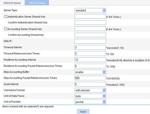
3. Configure RADIUS parameters as described in Table 14.
4. Click Apply.
|
Item |
Description |
|
Server Type |
Specify the type of the RADIUS server supported by the device, including: · extended: Specifies an extended RADIUS server (usually a CAMS or iMC server). That is, the RADIUS client and RADIUS server communicate using the proprietary RADIUS protocol and packet format. · standard: Specifies a standard RADIUS server. That is, the RADIUS client and RADIUS server communicate using the standard RADIUS protocol and packet format defined in RFC 2138/2139 or later. |
|
Authentication Server Shared Key |
Specify and confirm the shared key for the authentication server. These two parameters must have the same values. |
|
Confirm Authentication Shared Key |
|
|
Accounting Server Shared Key |
Specify and confirm the shared key for the accounting server. These two parameters must have the same values. |
|
Confirm Accounting Shared Key |
|
|
NAS-IP |
Specify the source IP address for the device to use in RADIUS packets to be sent to the RADIUS server. It is recommended to use a loopback interface address instead of a physical interface address as the source IP address, because if the physical interface is down, the response packets from the server cannot reach the device. |
|
Timeout Interval |
Set the RADIUS server response timeout. |
|
Timeout Retransmission Times |
Set the maximum number of transmission attempts. The product of the timeout value and the number of retransmission attempts cannot exceed 75. |
|
Realtime-Accounting Interval |
Set the real-time accounting interval, whose value must be n times 3 (n is an integer). To implement real-time accounting on users, it is necessary to set the real-time accounting interval. After this parameter is specified, the device will send the accounting information of online users to the RADIUS server every the specified interval. The value of the real-time accounting interval is related to the requirement on the performance of the NAS and RADIUS server. The smaller the value, the higher the requirement. It is recommended to set a large value if the number of users is equal to or larger than 1000. A good practice is to use the recommended interval values shown in “Configuration guidelines.” |
|
Realtime-Accounting Packet Retransmission Times |
Set the maximum number of real-time accounting request retransmission times. |
|
Stop-Accounting Buffer |
Enable or disable buffering stop-accounting requests without responses in the device. |
|
Stop-Accounting Packet Retransmission Times |
Set the maximum number of transmission attempts if no response is received for the stop-accounting packet. |
|
Quiet Interval |
Specify the interval the RADIUS servers have to wait before being active |
|
Username Format |
Set the format of username sent to the RADIUS server. A username is generally in the format of userid@isp-name, of which isp-name is used by the device to determine the ISP domain to which a user belongs. If a RADIUS server does not accept a username including an ISP domain name, you can configure the device to remove the domain name of a username before sending it to the RADIUS server. without-domain: Specifies to remove the domain name of a username that is to be sent to the RADIUS server. with-domain: Specifies to keep the domain name of a username that is to be sent to the RADIUS server. |
|
Unit of Data Flows |
Specify the unit for data flows sent to the RADIUS server, which can be: · byte · kilo-byte · mega-byte · giga-byte |
|
Unit of Packets |
Specify the unit for data packets sent to the RADIUS server, which can be · one-packet · kilo-packet · mega-packet · giga-packet |
RADIUS configuration example
Network requirements
As shown in Figure 90, configure the switch to use the RADIUS server for user authentication and accounting (record the online duration of the Telnet user).
Configure an account for the Telnet user on the RADIUS server that runs CAMS or iMC. Leave the server using the default ports for authentication and accounting).
Set the shared keys for authentication and accounting exchanges between the switch and server to expert.
Configure the switch to remove domain names from the usernames sent to the RADIUS server.
Configuration procedure
|
|
NOTE: You must enable the Telnet server function, and configure the switch to use AAA for authentication, authorization and accounting of Telnet users. Detailed configuration steps are not shown. |
1. Assign IP addresses to the interfaces. (Details not shown)
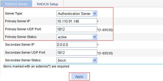
2. Configure RADIUS scheme system:
a. Select Authentication > RADIUS from the navigation tree to enter the RADIUS server configuration page.
b. To configure the primary authentication server, select the server type Authentication Server, enter the IP address 10.110.91.146, enter the UDP port number 1812, select the state active, and click Apply.
Figure 91 Configure the RADIUS authentication server
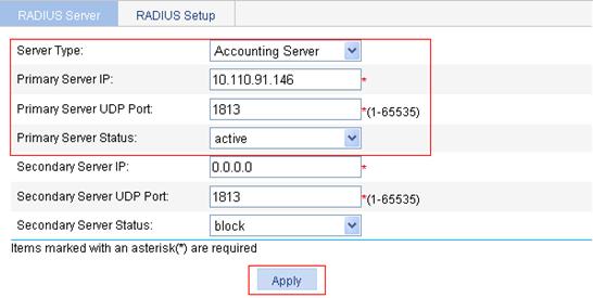
c. To configure the primary accounting server, select the server type Accounting Server, enter the IP address 10.110.91.146, enter the UDP port number 1813, select the state active, and click Apply.
Figure 92 Configure the RADIUS accounting server
d. To configure RADIUS communication parameters, click the RADIUS Setup tab and do the following:
¡ Select the server type extended.
¡ Select the Authentication Server Shared Key box and enter the shared key expert.
¡ Enter expert again in the Confirm Authentication Shared Key box.
¡ Select the Accounting Server Shared Key box and enter the shared key expert.
¡ Enter expert again in the Confirm Accounting Shared Key box.
¡ Select the username format without-domain.
e. Click Apply.
Figure 93 Configure RADIUS parameters
3. Create an ISP domain.
a. Select Authentication > AAA from the navigation tree.
The domain setup page appears.
b. Enter the domain name test.
c. Select Enable to use the domain as the default domain.
d. Click Apply.
Figure 94 Create an ISP domain
4. Configure the AAA authentication scheme for the ISP domain.
a. Click the Authentication tab.
b. Select the domain name test.
c. Click the Default AuthN box, and select the authentication mode RADIUS and the RADIUS scheme system.
d. Click Apply.
A configuration progress dialog box appears.
Figure 95 Configure the AAA authentication method for the ISP domain

e. After the configuration process is complete, click Close.
Figure 96 Configuration progress dialog box

5. Configure the AAA authorization scheme for the ISP domain.
a. Click the Authorization tab.
b. Select the domain name test.
c. Click the Default AuthZ box, and select the authorization mode RADIUS and the RADIUS scheme system.
d. Click Apply.
A configuration progress dialog box appears.
e. After the configuration process is complete, click Close.
Figure 97 Configure the AAA authorization method for the ISP domain
6. Configure the AAA accounting scheme for the ISP domain.
a. Click the Accounting tab.
b. Select the domain name test.
c. Click the Accounting Optional box and select Enable from the list.
d. Click the Default Accounting box, and select the accounting mode RADIUS and the RADIUS scheme system.
e. Click Apply.
A configuration progress dialog box appears.
f. After the configuration process is complete, click Close.
Figure 98 Configure the AAA accounting method for the ISP domain
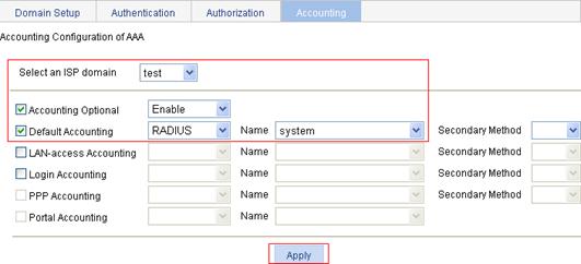
Configuration guidelines
When you configure the RADIUS client, follow these guidelines:
· Accounting for FTP users is not supported.
· If you remove the accounting server used for online users, the device cannot send real-time accounting requests and stop-accounting messages for the users to the server, and the stop-accounting messages are not buffered locally.
· The status of RADIUS servers—blocked or active—determines which servers the device will communicate with or turn to when the current servers are not available. In practice, you can specify one primary RADIUS server and multiple secondary RADIUS servers, with the secondary servers that function as the backup of the primary servers. Generally, the device chooses servers based on these rules:
¡ When the primary server is in active state, the device communicates with the primary server. If the primary server fails, the device changes the state of the primary server to blocked, starts a quiet timer for the server, and turns to a secondary server in active state (a secondary server configured earlier has a higher priority). If the secondary server is unreachable, the device changes the state of the secondary server to blocked, starts a quiet timer for the server, and continues to check the next secondary server in active state. This search process continues until the device finds an available secondary server or has checked all secondary servers in active state. If the quiet timer of a server expires or an authentication or accounting response is received from the server, the status of the server changes back to active automatically, but the device does not check the server again during the authentication or accounting process. If no server is found reachable during one search process, the device considers the authentication or accounting attempt a failure.
¡ Once the accounting process of a user starts, the device keeps sending the user’s real-time accounting requests and stop-accounting requests to the same accounting server. If you remove the accounting server, real-time accounting requests and stop-accounting requests for the user cannot be delivered to the server any more.
¡ If you remove an authentication or accounting server in use, the communication of the device with the server will soon time out, and the device will look for a server in active state from scratch: it checks the primary server (if any) first and then the secondary servers in the order they are configured.
¡ When the primary server and secondary servers are all in blocked state, the device communicates with the primary server. If the primary server is available, its statues changes to active. Otherwise, its status remains to be blocked.
¡ If one server is in active state but all the others are in blocked state, the device only tries to communicate with the server in active state, even if the server is unavailable.
¡ After receiving an authentication/accounting response from a server, the device changes the status of the server identified by the source IP address of the response to active if the current status of the server is blocked.
· Use a proper real-time accounting intervals according to the number of users.
Table 15 Recommended real-time accounting intervals
|
Number of users |
Real-time accounting interval (in minutes) |
|
1 to 99 |
3 |
|
100 to 499 |
6 |
|
500 to 999 |
12 |
|
≥1000 |
≥15 |
This module allows you to configure local users and user groups.
User overview
Local user
A local user represents a set of user attributes configured on a device (such as the user password, use type, service type, and authorization attribute), and is uniquely identified by the username. For a user requesting a network service to pass local authentication, you must add an entry as required in the local user database of the device. For more information about local authentication, see the chapter “AAA configuration.”
User group
A user group consists of a group of local users and has a set of local user attributes. You can configure local user attributes for a user group to implement centralized management of user attributes for the local users in the group. All local users in a user group inherit the user attributes of the group, but if you configure user attributes for a local user, the settings of the local user take precedence over the settings for the user group.
By default, every newly added local user belongs to a user group named system, which is automatically created by the system.
Configuring users
Configuring a local user
1. Select Authentication > Users from the navigation tree.
The local user management page appears, displaying all local users.
Figure 99 Local user management page
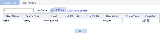
2. Click Add to enter the local user configuration page.
Figure 100 Local user configuration page

3. Configure a local user as described in Table 16.
4. Click Apply.
|
Item |
Description |
|
Username |
Specify a name for the local user. |
|
Password |
Specify and confirm the password of the local user. The settings of these two fields must be the same.
Do not specify a password that starts with spaces. Spaces at the beginning of the password string will be ignored, but they count at the user login page. |
|
Confirm |
|
|
Group |
Select a user group for the local user. For information about user groupconfiguration, see “Configuring a user group.” |
|
Service-type |
Select the service types for the local user to use, including web, FTP, Telnet, PPP, Portal, LAN access (accessing through the Ethernet, such as 802.1X users), and SSH.
· If you do not specify any service type for a local user, the user cannot pass local authentication to log in. · For a user to log in through web, you must specify the Telnet service for the user. |
|
Expire-time |
Specify an expiration time for the local user, in the format HH:MM:SS-YYYY/MM/DD. When authenticating a local user with the expiration time argument configured, the access device checks whether the expiration time has elapsed. If yes, the device prevents the user from logging in. |
|
Level |
Specify authorization attributes for the local user, including: · Privilege level, which can be Visitor, Monitor, Configure, or Management, in ascending order of priority. · Authorization VLAN · Authorization ACL · User profile
Every configurable authorization attribute has its definite application environments and purposes. When configuring authorization attributes for a local user, consider which attributes are needed and which are not: · The Level option is effective for FTP, Telnet, and SSH users. · The ACL and User-profile options are effective for PPP users. · The VLAN, ACL and User-profile options are effective for LAN access users. |
|
VLAN |
|
|
ACL |
|
|
User-profile |
Configuring a user group
1. Select Authentication > Users from the navigation tree.
2. Click the User Group tab.
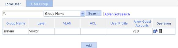
3. Click Add to enter the user group configuration page.
Figure 102 User group configuration page
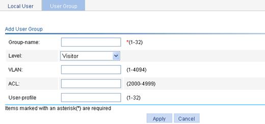
4. Configure the user group as described in Table 17.
5. Click Apply.
|
Item |
Description |
|
Group-name |
Specify a name for the user group. |
|
Level |
Select an authorization level for the user group, which can be Visitor, Monitor, Configure, or Management, in ascending order of priority. |
|
VLAN |
Specify the VLAN to be authorized to users of the user group after the users pass authentication. |
|
ACL |
Specify the ACL to be used by the access device to control the access of users of the user group after the users pass authentication. |
|
User-profile |
Specify the user profile for the user group. |
PKI overview
The Public Key Infrastructure (PKI) is a general security infrastructure for providing information security through public key technologies, and it is the most widely applied encryption mechanism currently. H3C's PKI system provides certificate management for IP Security (IPsec), Secure Sockets Layer (SSL), and WLAN Authentication and Privacy Infrastructure (WAPI).
PKI, also called asymmetric key infrastructure, uses a key pair to encrypt and decrypt data. The key pair consists of a private key and a public key. The private key must be kept secret but the public key needs to be distributed. Data encrypted by one of the two keys can only be decrypted by the other.
A key problem of PKI is how to manage the public keys. Currently, PKI employs the digital certificate mechanism to solve this problem. The digital certificate mechanism binds public keys to their owners, helping distribute public keys in large networks securely.
With digital certificates, the PKI system provides network communication and e-commerce with security services such as user authentication, data non-repudiation, data confidentiality, and data integrity.
The PKI technology can satisfy the security requirements of online transactions. As an infrastructure, PKI has a wide range of applications. Here are some application examples:
· VPN—A virtual private network (VPN) is a private data communication network built on the public communication infrastructure. A VPN can leverage network layer security protocols (for instance, IPsec) in conjunction with PKI-based encryption and digital signature technologies to achieve confidentiality.
· Secure email—Emails require confidentiality, integrity, authentication, and non-repudiation. PKI can address these needs. The secure email protocol that is currently developing rapidly is Secure/Multipurpose Internet Mail Extensions (S/MIME), which is based on PKI and allows for transfer of encrypted mails with signature.
· Web security—For Web security, two peers can establish a Secure Sockets Layer (SSL) connection first for transparent and secure communications at the application layer. With PKI, SSL enables encrypted communications between a browser and a server. Both the communication parties can verify the identity of each other through digital certificates.
|
|
NOTE: For more information about PKI, see H3C WX3000E Series Wireless Switches Switching Engine Configuration Guide. |
Configuring PKI
The device supports the following PKI certificate request modes:
· Manual—In manual mode, you need to retrieve a CA certificate, generate a local RSA key pair, and submit a local certificate request for an entity.
· Auto—In auto mode, an entity automatically requests a certificate through the Simple Certification Enrollment Protocol (SCEP) when it has no local certificate or the present certificate is about to expire.
You can specify the PKI certificate request mode for a PKI domain. Different PKI certificate request modes require different configurations.
Recommended configuration procedure for manual request
|
Step |
Remarks |
|
Required Create a PKI entity and configure the identity information. A certificate is the binding of a public key and an entity, where an entity is the collection of the identity information of a user. A CA identifies a certificate applicant by entity.
The identity settings of an entity must be compliant to the CA certificate issue policy. Otherwise, the certificate request might be rejected. |
|
|
Required Create a PKI domain, setting the certificate request mode to Manual. Before requesting a PKI certificate, an entity needs to be configured with some enrollment information, which is referred to as a PKI domain. A PKI domain is intended only for convenience of reference by other applications like IKE and SSL, and has only local significance. |
|
|
Required Generate a local RSA key pair. By default, no local RSA key pair exists. Generating an RSA key pair is an important step in certificate request. The key pair includes a public key and a private key. The private key is kept by the user, and the public key is transferred to the CA along with some other information.
If a local certificate already exists, you must remove the certificate before generating a new key pair, so as to keep the consistency between the key pair and the local certificate. |
|
|
4. Retrieving the CA certificate |
Required Certificate retrieval serves the following purposes: · Locally store the certificates associated with the local security domain for improved query efficiency and reduced query count, · Prepare for certificate verification.
If a local CA certificate already exists, you cannot perform the CA certificate retrieval operation. This will avoid possible mismatch between certificates and registration information resulting from relevant changes. To retrieve the CA certificate, you need to remove the CA certificate and local certificate first. |
|
Required When requesting a certificate, an entity introduces itself to the CA by providing its identity information and public key, which will be the major components of the certificate. A certificate request can be submitted to a CA in online mode or offline mode. · In online mode, if the request is granted, the local certificate will be retrieved to the local system automatically. · In offline mode, you need to retrieve the local certificate by an out-of-band means.
If a local certificate already exists, you cannot perform the local certificate retrieval operation. This will avoid possible mismatch between the local certificate and registration information resulting from relevant changes. To retrieve a new local certificate, you need to remove the CA certificate and local certificate first. |
|
|
Optional Destroy the existing RSA key pair and the corresponding local certificate. If the certificate to be retrieved contains an RSA key pair, you need to destroy the existing key pair. Otherwise, the retrieving operation will fail. |
|
|
Optional Retrieve an existing certificate. |
|
|
Optional Retrieve a CRL and display its contents. |
Recommended configuration procedure for automatic request
|
Step |
Remarks |
|
Required Create a PKI entity and configure the identity information. A certificate is the binding of a public key and an entity, where an entity is the collection of the identity information of a user. A CA identifies a certificate applicant by entity. The identity settings of an entity must be compliant to the CA certificate issue policy. Otherwise, the certificate request might be rejected. |
|
|
Required Create a PKI domain, setting the certificate request mode to Auto. Before requesting a PKI certificate, an entity needs to be configured with some enrollment information, which is referred to as a PKI domain. A PKI domain is intended only for convenience of reference by other applications like IKE and SSL, and has only local significance. |
|
|
Optional Destroy the existing RSA key pair and the corresponding local certificate. If the certificate to be retrieved contains an RSA key pair, you need to destroy the existing key pair. Otherwise, the retrieving operation will fail. |
|
|
Optional Retrieve an existing certificate. |
|
|
Optional Retrieve a CRL and display its contents. |
Creating a PKI entity
1. Select Authentication > PKI from the navigation tree.
The PKI entity list page is displayed by default.
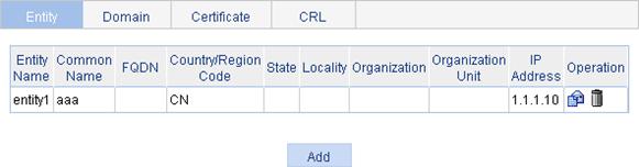
2. Click Add.
Figure 104 PKI entity configuration page
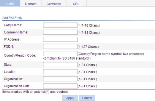
3. Configure the parameters as described in Table 18.
4. Click Apply.
|
Item |
Description |
|
Entity Name |
Enter the name for the PKI entity. |
|
Common Name |
Enter the common name for the entity. |
|
IP Address |
Enter the IP address of the entity. |
|
FQDN |
Enter the fully qualified domain name (FQDN) for the entity. An FQDN is a unique identifier of an entity on the network. It consists of a host name and a domain name and can be resolved to an IP address. For example, www.whatever.com is an FQDN, where www indicates the host name and whatever.com the domain name. |
|
Country/Region Code |
Enter the country or region code for the entity. |
|
State |
Enter the state or province for the entity. |
|
Locality |
Enter the locality for the entity. |
|
Organization |
Enter the organization name for the entity. |
|
Organization Unit |
Enter the unit name for the entity. |
Creating a PKI domain
1. Select Authentication > PKI from the navigation tree.
2. Click the Domain tab.
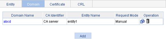
3. Click Add.
4. Click Display Advanced Config to display the advanced configuration items.
Figure 106 PKI domain configuration page
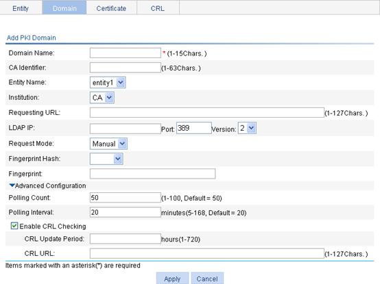
5. Configure the parameters as described in Table 19.
6. Click Apply.
|
Item |
Description |
|
Domain Name |
Enter the name for the PKI domain. |
|
CA Identifier |
Enter the identifier of the trusted CA. An entity requests a certificate from a trusted CA. The trusted CA takes the responsibility of certificate registration, distribution, and revocation, and query. In offline mode, this item is optional. In other modes, this item is required. |
|
Entity Name |
Select the local PKI entity. When submitting a certificate request to a CA, an entity needs to show its identity information. Available PKI entities are those that have been configured. |
|
Institution |
Select the authority for certificate request. · CA—Indicates that the entity requests a certificate from a CA. · RA—Indicates that the entity requests a certificate from an RA. RA is recommended. |
|
Requesting URL |
Enter the URL of the RA. The entity will submit the certificate request to the server at this URL through the SCEP protocol. The SCEP protocol is intended for communication between an entity and an authentication authority. In offline mode, this item is optional. In other modes, this item is required.
This item does not support domain name resolution. |
|
LDAP IP |
Enter the IP address, port number and version of the LDAP server. In a PKI system, the storage of certificates and CRLs is a crucial problem, which is usually addressed by deploying an LDAP server. |
|
Port |
|
|
Version |
|
|
Request Mode |
Select the online certificate request mode, which can be auto or manual. |
|
Password Encrypt |
Click this box to display the password in cipher text. This box is available only when the certificate request mode is set to Auto. |
|
Password |
Enter the password for certificate revocation. This item is available only when the certificate request mode is set to Auto. |
|
Fingerprint Hash |
Specify the fingerprint used for verifying the CA root certificate. After receiving the root certificate of the CA, an entity needs to verify the fingerprint of the root certificate, namely, the hash value of the root certificate content. This hash value is unique to every certificate. If the fingerprint of the root certificate does not match the one configured for the PKI domain, the entity will reject the root certificate. · If you specify MD5 as the hash algorithm, enter an MD5 fingerprint. The fingerprint must a string of 32 characters in hexadecimal notation. · If you specify SHA1 as the hash algorithm, enter an SHA1 fingerprint. The fingerprint must a string of 40 characters in hexadecimal notation. · If you do not specify the fingerprint hash, do not enter any fingerprint. The entity will not verify the CA root certificate, and you yourself must make sure that the CA server is trusted.
The fingerprint must be configured if you specify the certificate request mode as Auto. If you specify the certificate request mode as Manual, you can leave the fingerprint settings null. If you do not configure the fingerprint, the entity will not verify the CA root certificate and you yourself must make sure that the CA server is trusted. |
|
Fingerprint |
|
|
Polling Count |
Set the polling interval and attempt limit for querying the certificate request status. After an entity makes a certificate request, the CA might need a long period of time if it verifies the certificate request in manual mode. During this period, the applicant needs to query the status of the request periodically to get the certificate as soon as possible after the certificate is signed. |
|
Polling Interval |
|
|
Enable CRL Checking |
Click this box to specify that CRL checking is required during certificate verification. |
|
CRL Update Period |
Enter the CRL update period, that is, the interval at which the PKI entity downloads the latest CRLs. This item is available after you click the Enable CRL Checking box. By default, the CRL update period depends on the next update field in the CRL file. |
|
CRL URL |
Enter the URL of the CRL distribution point. This item is available after you click the Enable CRL Checking box. When the URL of the CRL distribution point is not set, you should acquire the CA certificate and a local certificate, and then acquire a CRL through SCEP.
This item does not support domain name resolution. |
Generating an RSA key pair
1. Select Authentication > PKI from the navigation tree.
2. Click the Certificate tab.
Figure 107 Certificate configuration page
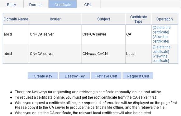
3. Click Create Key.
Figure 108 Key pair parameter configuration page
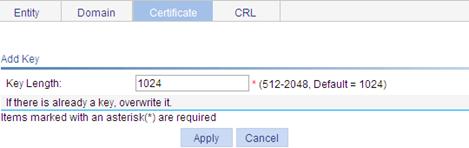
4. Enter 1024 as the key length.
5. Click Apply.
Destroying the RSA key pair
1. Select Authentication > PKI from the navigation tree.
2. Click the Certificate tab.
3. Click Destroy Key.
4. Click Apply to destroy the existing RSA key pair and the corresponding local certificate.
Figure 109 Key pair destruction page
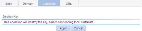
Retrieving a certificate
You can download an existing CA certificate or local certificate from the CA server and save it locally. To do so, you can use offline mode or online. In offline mode, you can retrieve a certificate by an out-of-band means like FTP, disk, email and then import it into the local PKI system.
To retrieve a certificate:
1. Select Authentication > PKI from the navigation tree.
2. Click the Certificate tab.
3. Click Retrieve Cert.
Figure 110 PKI certificate retrieval page
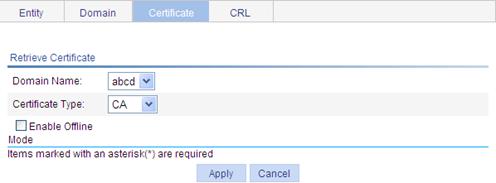
4. Configure the parameters as described in Table 20.
5. Click Apply.
|
Item |
Description |
|
Domain Name |
Select the PKI domain for the certificate. |
|
Certificate Type |
Select the type of the certificate to be retrieved, which can be CA or local. |
|
Enable Offline Mode |
Click this box to retrieve a certificate in offline mode (that is, by an out-of-band means like FTP, disk, or email) and then import the certificate into the local PKI system. The following configuration items are displayed if you click this box. |
|
Get File From Device |
Specify the path and name of the certificate file. · If the certificate file is saved on the device, select Get File From Device and then specify the path of the file on the device. · If the certificate file is saved on a local PC, select Get File From PC and. then specify the path to the file and select the partition of the device for saving the file. |
|
Get File From PC |
|
|
Password |
Enter the password for protecting the private key, which was specified when the certificate was exported. |
6. After retrieving a certificate, you can click View Cert corresponding to the certificate from the PKI certificates list to display the contents of the certificate.
Figure 111 Certificate information
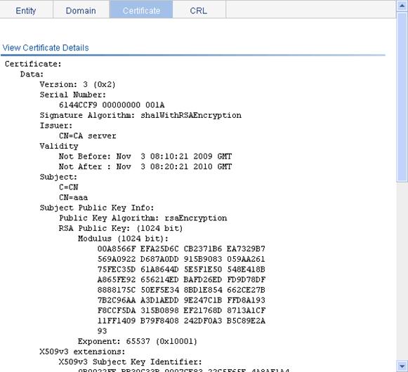
Requesting a local certificate
1. Select Authentication > PKI from the navigation tree.
2. Click the Certificate tab.
3. Click Request Cert.
Figure 112 Local certificate request page
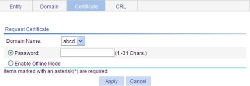
4. Configure the parameters as described in Table 21.
|
Item |
Description |
|
Domain Name |
Select the PKI domain for the certificate. |
|
Password |
Enter the password for certificate revocation. |
|
Enable Offline Mode |
Select this option to request a certificate in offline mode, that is, by an out-of-band means like FTP, disk, or email. |
5. Click Apply.
If you use the offline mode to request a local certificate, the system displays the offline certificate request information. You can submit the information to the CA to request a local certificate.
Figure 113 Offline certificate request information page
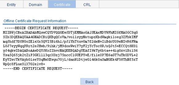
Retrieving and displaying a CRL
1. Select Authentication > PKI from the navigation tree.
2. Click the CRL tab.
Figure 114 CRL page
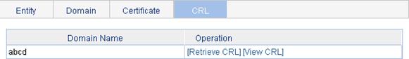
3. Click Retrieve CRL to retrieve the CRL of a domain.
4. Click View CRL for the domain to display the contents of the CRL.
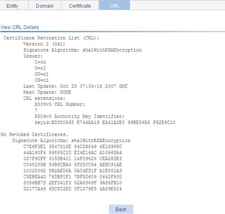
|
Field |
Description |
|
Version |
CRL version number |
|
Signature Algorithm |
Signature algorithm that the CRL uses |
|
Issuer |
CA that issued the CRL |
|
X509v3 Authority Key Identifier |
Identifier of the CA that issued the certificate and the certificate version (X509v3). |
|
keyid |
Pubic key identifier A CA might have multiple key pairs, and this field identifies which key pair is used for the CRL signature. |
PKI configuration example
Network requirements
As shown in Figure 116, configure the switch that acts as the PKI entity, so that:
· The switch submits a local certificate request to the CA server, which runs the RSA Keon software.
· The switch acquires CRLs for certificate verification.
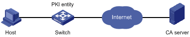
Configuring the CA server
1. Create a CA server named myca.
In this example, you must first configure the basic attributes of Nickname and Subject DN on the CA server: the nickname is the name of the trusted CA, and the subject DN is the DN attributes of the CA, including the common name (CN), organization unit (OU), organization (O), and country (C). Leave the default values of the other attributes.
2. Configure extended attributes.
After configuring the basic attributes, you need to perform configuration on the Jurisdiction Configuration page of the CA server. This includes selecting the proper extension profiles, enabling the SCEP autovetting function, and adding the IP address list for SCEP autovetting.
3. Configure the CRL publishing behavior
After completing the configuration, you need to perform CRL related configurations.
In this example, select the local CRL publishing mode of HTTP and set the HTTP URL to http://4.4.4.133:447/myca.crl.
After the configuration, make sure that the system clock of the switch is synchronous to that of the CA, so that the switch can request certificates and retrieve CRLs properly.
Configuring the switch
1. Create a PKI entity.
a. Select Authentication > PKI from the navigation tree.
The PKI entity list page is displayed by default.
b. Click Add.
c. Enter aaa as the PKI entity name.
d. Enter ac as the common name.
e. Click Apply.
Figure 117 Configure a PKI entity
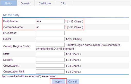
2. Create a PKI domain.
a. Click the Domain tab.
b. Click Add.
c. Enter torsa as the PKI domain name.
d. Enter myca as the CA identifier.
e. Select aaa as the local entity.
f. Select CA as the authority for certificate request.
g. Enter http://4.4.4.133:446/c95e970f632d27be5e8cbf80e971d9c4a9a93337 as the URL for certificate request. The URL must be in the format of http://host:port/Issuing Jurisdiction ID, where Issuing Jurisdiction ID is the hexadecimal string generated on the CA.
h. Select Manual as the certificate request mode.
i. Click the collapse button for the Advanced Configuration option.
j. Click the Enable CRL Checking box.
k. Enter http://4.4.4.133:447/myca.crl as the CRL URL.
l. Click Apply.
A dialog box appears, asking "Fingerprint of the root certificate not specified. No root certificate validation will occur. Continue?"
m. Click OK.
Figure 118 Configure a PKI domain
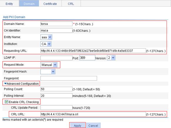
3. Generate an RSA key pair.
a. Click the Certificate tab.
b. Click Create Key.
c. Enter 1024 as the key length.
d. Click Apply to generate an RSA key pair.
Figure 119 Generate an RSA key pair
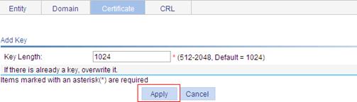
4. Retrieve the CA certificate.
a. Click the Certificate tab.
b. Click Retrieve Cert.
c. Select torsa as the PKI domain.
d. Select CA as the certificate type.
e. Click Apply.
Figure 120 Retrieve the CA certificate
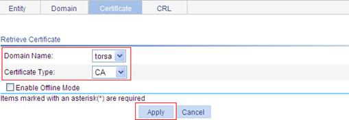
5. Request a local certificate.
a. Click the Certificate tab.
b. Click Request Cert.
c. Select torsa as the PKI domain.
d. Select Password and then enter “challenge-word” as the password.
e. Click Apply.
The system displays “Certificate request has been submitted”.
f. Click OK to confirm.
Figure 121 Request a local certificate
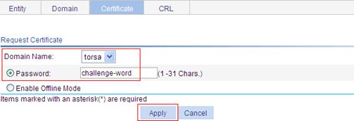
6. Retrieve the CRL.
a. Click the CRL tab.
b. Click Retrieve CRL of the PKI domain of torsa.
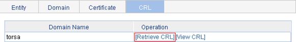
Verifying the configuration
After the configuration, you can select Authentication > PKI from the navigation tree and click the Certificate tab to view detailed information about the retrieved CA certificate and the local certificate, or select click the CRL tab to view detailed information about the retrieved CRL.
Configuration guidelines
When you configure PKI, note the following guidelines:
· Make sure the clocks of entities and the CA are synchronous. Otherwise, the validity period of certificates will be abnormal.
· The Windows 2000 CA server has some restrictions on the data length of a certificate request. If the PKI entity identity information in a certificate request goes beyond a certain limit, the server will not respond to the certificate request.
· The SCEP plug-in is required when you use the Windows Server as the CA. In this case, you need to specify RA as the authority for certificate request when configuring the PKI domain.
· The SCEP plug-in is not required when you use the RSA Keon software as the CA. In this case, you need to specify CA as the authority for certificate request when configuring the PKI domain.