- Table of Contents
- Related Documents
-
| Title | Size | Download |
|---|---|---|
| 08-Security | 192.06 KB |
Contents
Port isolation group configuration·
Configuring an isolation group
Recommended configuration procedure
Configuring member ports for a port isolation group
Port isolation configuration example
Authorized IP configuration example
Overview
Port isolation enables isolating Layer 2 traffic for data privacy and security without using VLANs. You can also use this feature to isolate the hosts in a VLAN from one another.
The device supports multiple isolation groups which can be configured manually. There is no restriction on the number of ports assigned to an isolation group.
|
|
NOTE: The member port of an aggregation group cannot be configured as the uplink port of an isolation group and vice versa. If you assign a port to an aggregation group and to an isolation group as the uplink port at the same time, the aggregation group configuration will take effect and the isolation group configuration will be removed for backward configuration file compatibility. For more information about link aggregation, see the chapter “Link aggregation and LACP configuration.” |
Usually, Layer 2 traffic cannot be forwarded between ports in different VLANs. However, Layer 2 traffic in the same VLAN can be bidirectionally transmitted within and outside the isolation group.
Configuring an isolation group
Recommended configuration procedure
|
Step |
Remarks |
|
Required. By default, no port isolation group exists. |
|
|
Required. You can configure multiple isolated ports for a port isolation group. By default, a port isolation group contains no isolated port. |
Adding port isolation groups
1. Select Security > Port Isolate Group from the navigation tree.
2. Click the Group Setup tab to enter the page shown in Figure 1.
On this page, you can add or remove port isolation groups.
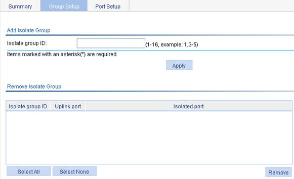
3. Add port isolation groups as described in Table 1.
4. Click Apply.
|
Item |
Description |
|
Isolate group ID |
Enter the IDs of the port isolation groups you want to add |
Configuring member ports for a port isolation group
1. Select Security > Port Isolate Group from the navigation tree.
2. Click the Port Setup tab to enter the page shown in Figure 2.
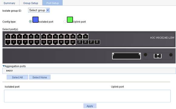
3. Configure member ports for the port isolation group as described in Table 2.
4. Click Apply.
The configuration progress dialog box appears.
5. After the success notification appears, click Close.
|
Item |
Description |
|
Isolate group ID |
Select the ID of the port isolation group to be configured |
|
Config type |
Specify the role of the port or ports in the isolation group. · Isolated port: Assign the port or ports to the isolation group as an isolated port or ports. · Uplink port: Assign the port to the isolation group as the uplink port.
The device does not support uplink ports. |
|
Select port(s) |
Select the port(s) you want to assign to the isolation group. You can click ports on the chassis front panel for selection; if aggregate interfaces are configured, they will be listed under the chassis panel for selection. After selecting Isolated port for Config type, you can select multiple ports to configure.
You cannot configure an isolated port in a port isolation group as the uplink port of the current or another port isolation group, but you can configure it as an isolated port of another port isolation group. |
|
Aggregation port |
· On the switch engine of a WX3000E series wireless switch, ports GigabitEthernet 1/0/29 and GigabitEthernet 1/0/30 are aggregated to BAGG 1. · On the control engine of a WX3000E series wireless switch, ports GigabitEthernet 1/0/1 and GigabitEthernet 1/0/2 are aggregated to BAGG 1. |
Port isolation configuration example
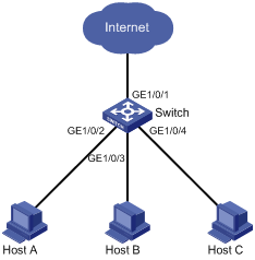
Network requirements
As shown in Figure 3:
· Campus network users Host A, Host B, and Host C are connected to GigabitEthernet 1/0/2, GigabitEthernet 1/0/3, and GigabitEthernet 1/0/4 of Switch.
· Switch is connected to the external network through GigabitEthernet 1/0/1.
· GigabitEthernet 1/0/1, GigabitEthernet 1/0/2, GigabitEthernet 1/0/3, and GigabitEthernet 1/0/4 belong to the same VLAN.
It is required that Host A, Host B, and Host C can access the external network while being isolated from one another on Layer 2.
Configuring port isolation
1. Add port isolation group 1:
a. Select Security > Port Isolate Group from the navigation tree.
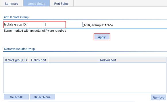
b. Click the Group Setup tab to enter the page shown in Figure 4.
c. Enter 1 in the Isolate group ID field.
d. Click Apply.
Figure 4 Add a port isolation group
2. Assign GigabitEthernet 1/0/2, GigabitEthernet 1/0/3, and GigabitEthernet 1/0/4 to port isolation group 1:
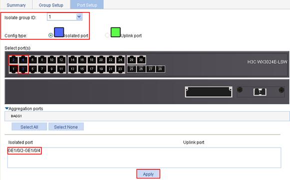
a. Click the Port Setup tab to enter the page shown in Figure 5.
b. Select 1 from the Isolate group ID list.
c. Select Isolated port for Config Type.
d. Select GigabitEthernet 1/0/2, GigabitEthernet 1/0/3, and GigabitEthernet 1/0/4 on the chassis front panel.
e. Click Apply.
A configuration progress dialog box appears.
f. After the success notification appears, click Close.
Figure 5 Configure isolated ports for port isolation group 1
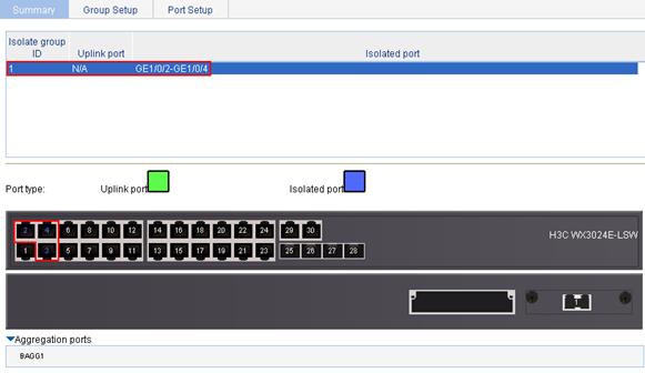
3. View information about the isolation group.
Click the Summary tab to enter the page shown in Figure 6. The page shows that port isolation group 1 contains isolated ports GigabitEthernet 1/0/2, GigabitEthernet 1/0/3, and GigabitEthernet 1/0/4.
Figure 6 Information about port isolation group 1
Overview
The authorized IP function is to associate the HTTP or Telnet service with an ACL to filter the requests of clients. Only the clients that pass the ACL filtering can access the device.
Configuring authorized IP
1. Select Security > Authorized IP from the navigation tree.
2. Click the Setup tab to enter the authorized IP configuration page, as shown in Figure 7.
Figure 7 Authorized IP configuration page
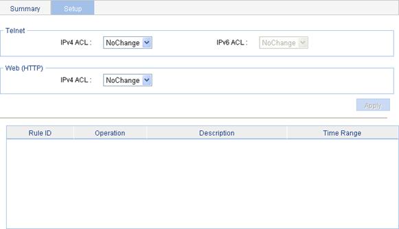
3. Configure authorized IP as described in Table 3.
4. Click Apply.
|
Item |
Description |
|
|
Telnet |
IPv4 ACL |
Associate the Telnet service with an IPv4 ACL. You can configure the IPv4 ACL to be selected by selecting QoS > ACL IPv4. |
|
IPv6 ACL |
Associate the Telnet service with an IPv6 ACL. You can configure the IPv6 ACL to be selected by selecting QoS > ACL IPv6. |
|
|
Web (HTTP) |
IPv4 ACL |
Associate the HTTP service with an IPv4 ACL. You can configure the IPv4 ACL to be selected by selecting QoS > ACL IPv4. |
Authorized IP configuration example
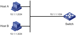
Network requirements
In Figure 8, configure Switch to deny telnet and HTTP requests from Host A , while permit telnet and HTTP requests from Host B.
Configuration procedure
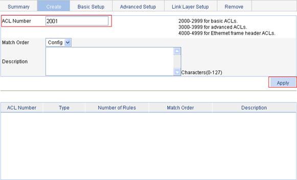
1. Create an ACL:
a. Select QoS > ACL IPv4 from the navigation tree.
b. Click the Create tab.
c. Type 2001 for ACL Number, as shown in Figure 9.
d. Click Apply.
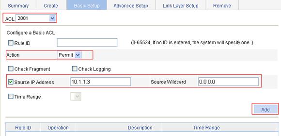
2. Configure an ACL rule to permit Host B:
a. Click the Basic Setup tab.
b. To configure an ACL rule to permit Host B:
¡ Select 2001 from the Select Access Control List (ACL) list.
¡ Select Permit from the Operation list.
¡ Select the Source IP Address box and then type 10.1.1.3.
¡ Type 0.0.0.0 in the Source Wildcard field.
c. Click Add.
Figure 10 Configure an ACL rule to permit Host B
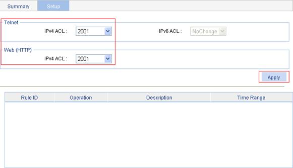
3. Configure authorized IP:
a. Select Security > Authorized IP from the navigation tree.
b. Click the Setup tab.
c. Select 2001 for IPv4 ACL in the Telnet field, and select 2001 for IPv4 ACL in the Web(HTTP) field, as shown in Figure 11.
d. Click Apply.
Figure 11 Configure authorized IP