- Table of Contents
- Related Documents
-
| Title | Size | Download |
|---|---|---|
| 06-Network | 2.02 MB |
Contents
Recommended configuration procedure
Recommended voice VLAN configuration procedures
Configuring voice VLAN globally
Configuring voice VLAN on a port
Adding OUI addresses to the OUI list
Example for configuring voice VLAN on a port in automatic voice VLAN assignment mode
Example for configuring a voice VLAN on a port in manual voice VLAN assignment mode
Configuring a MAC address entry
Setting the aging time of MAC address entries
MAC address configuration example
Recommended configuration procedure
Displaying MSTP information of a port
Link aggregation and LACP configuration
Recommended configuration procedures
Creating a link aggregation group
Displaying information of an aggregate interface
Displaying information of LACP-enabled ports
Link aggregation and LACP configuration example
Recommended configuration procedure
Configuring LLDP settings on ports
Configuring LLDP settings on ports individually
Configuring LLDP settings on ports in batch
Displaying LLDP information for a port
Displaying global LLDP information
Displaying LLDP information received from LLDP neighbors
LLDP basic settings configuration example
CDP-compatible LLDP configuration example
Introduction to gratuitous ARP
Static ARP configuration example
ARP attack defense configuration
Recommended configuration procedure
Enabling IGMP snooping globally
Configuring IGMP snooping in a VLAN
Configuring IGMP snooping port functions
Display IGMP snooping multicast entry information
IGMP snooping configuration example
IPv4 and IPv6 routing configuration·
Displaying the IPv4 active route table
Displaying the IPv6 active route table
IPv4 static route configuration example
IPv6 static route configuration example
Recommended configuration procedure
Creating a static address pool for the DHCP server
Creating a dynamic address pool for the DHCP server
Enabling the DHCP server on an interface
Display the information of assigned IP addresses
Configuring the DHCP relay agent
Recommended configuration procedure
Enabling DHCP and configuring advanced parameters for the DHCP relay agent
Enabling the DHCP relay agent on an interface
Configuring and displaying clients' IP-to-MAC bindings
Recommended configuration procedure
Configuring DHCP snooping functions on an interface
Displaying clients' IP-to-MAC bindings
DHCP server configuration examples
Static IP address assignment configuration example
Dynamic IP address assignment configuration example
DHCP relay agent configuration example
DHCP snooping configuration example
Configuring service management
VLAN configuration
Overview
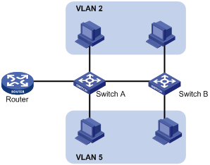
Ethernet is a network technology based on the Carrier Sense Multiple Access/Collision Detect (CSMA/CD) mechanism. As the medium is shared, collisions and excessive broadcasts are common on an Ethernet. To address the issue, virtual LAN (VLAN) was introduced to break a LAN down into separate VLANs. VLANs are isolated from each other at Layer 2. A VLAN is a bridging domain, and all broadcast traffic is contained within it, as shown in Figure 1.
You can implement VLANs based on a variety of criteria. The web interface, however, is available only for port-based VLANs, which group VLAN members by port. A port forwards traffic for a VLAN only after it is assigned to the VLAN.
|
|
NOTE: For more information about VLAN, see H3C WX3000E Series Wireless Switches Switching Engine Configuration Guide. |
Recommended configuration procedure
Use one of the following two approaches or combine the following two approaches to configure a VLAN:
· Approach I: modify a VLAN, as shown in Table 1.
· Approach II: modify a port, as shown in Table 2.
|
Step |
Remarks |
|
Required Create one or multiple VLANs |
|
|
Required Reduce the range of VLANs available for selection during related operations. Configure a subset of all existing VLANs. This step is required before displaying, modifying, or removing a VLAN. |
|
|
Required Configure the untagged member ports and tagged member ports of the VLAN, or remove the specified ports from the VLAN. |
|
Step |
Remarks |
|
Required Create one or multiple VLANs |
|
|
Required Configure ports as the untagged members or tagged members of VLANs, or remove ports from VLANs; configure the link type and PVID of the ports. |
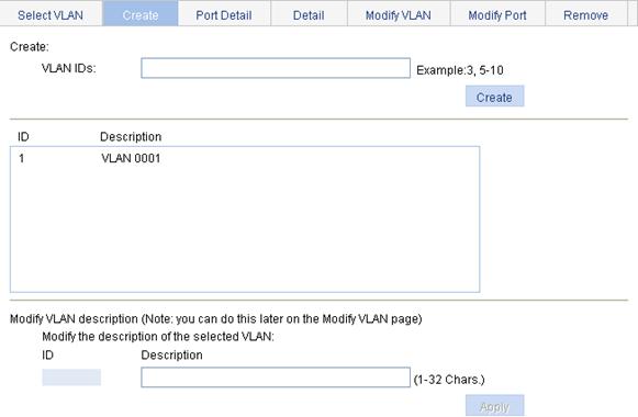
Creating VLANs
1. Select Network > VLAN from the navigation tree.
2. Click Create to enter the page for creating VLANs, as shown in Figure 2.
3. Enter the VLAN ID or VLAN ID range.
4. Click Apply.
Selecting VLANs
1. Select Network > VLAN from the navigation tree, and the Select VLAN tab is displayed by default.
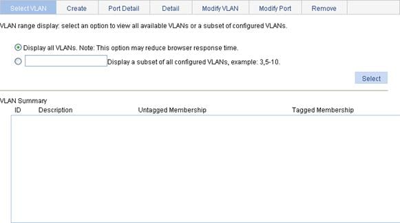
2. Select Display all VLANs or select Display a subset of all configured VLANs and specify a VLAN range.
3. Click Select.
Modifying a VLAN
1. Select Network > VLAN from the navigation tree.
2. Click Modify VLAN to enter the page for modifying a VLAN, as shown in Figure 4.
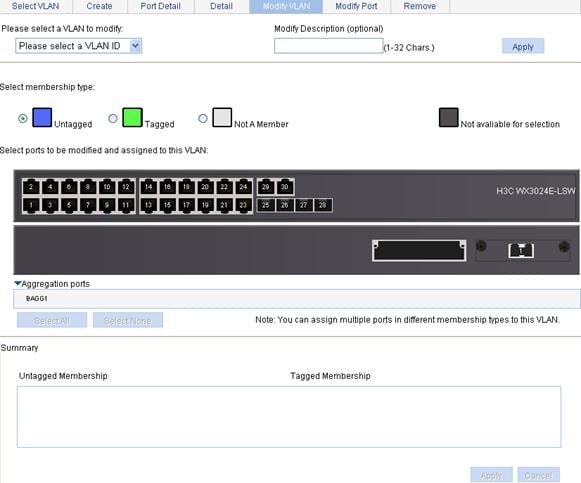
3. Modify a VLAN as described in Table 3.
4. Click Apply to view the configuration progress in the popup dialog box.
5. After the configuration succeeds, close the dialog box.
|
Item |
Description |
|
|
Please select a VLAN to modify |
Select the VLAN to be modified. Select a VLAN from the list. The VLANs available for selection are created first and then selected on the page for selecting VLANs. |
|
|
Modify Description |
Modify the description string of the selected VLAN. By default, the description string of a VLAN is its VLAN ID, such as VLAN 0001. |
|
|
Select membership type |
Untagged |
Set the member type of the port to be modified in the VLAN. Select the Untagged, Tagged, or Not A Member option: · Untagged: Indicates that the port sends the traffic of the VLAN with the VLAN tag removed. · Tagged: Indicates that the port sends the traffic of the VLAN without removing the VLAN tag. · Not A Member: Removes the port from the VLAN. |
|
Tagged |
||
|
Not A Member |
||
|
Select ports to be modified and assigned to this VLAN |
Select the ports to be modified in the selected VLAN. Click the ports to be modified on the chassis front panel. You can select one or more ports. If aggregate interfaces are configured on the device, the page displays a list of aggregate interfaces below the chassis front panel. You can select aggregate interfaces from this list.
When you configure an access port as a tagged member of a VLAN, the link type of the port is automatically changed into hybrid. |
|
Modifying ports
1. Select Network > VLAN from the navigation tree.
2. Click Modify Port to enter the page for modifying ports, as shown in Figure 5.
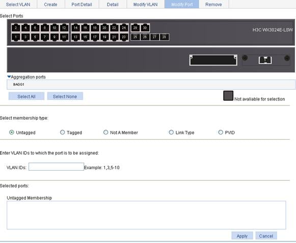
3. Modify a port as described in Table 4.
4. Click Apply to view the configuration progress in the popup dialog box.
5. After the configuration succeeds, close the dialog box.
|
Item |
Description |
|
|
Select Ports |
Select the ports to be modified. Click the ports to be modified on the chassis front panel. You can select one or more ports. If aggregate interfaces are configured on the device, the page displays a list of aggregate interfaces below the chassis front panel. You can select aggregate interfaces from this list. |
|
|
Select membership type |
Untagged |
Set the member types of the selected ports to be modified in the specified VLANs. Select the Untagged, Tagged, or Not A Member option: · Untagged: Assigns the selected ports to the specified VLANs as untagged members. After that, the ports send the traffic of those VLANs with the VLAN tags removed. · Tagged: Assigns the selected ports to the specified VLANs as tagged members. After that, the ports send the traffic of those VLANs without removing the VLAN tags. · Not A Member: Removes the selected ports from the specified VLANs. |
|
Tagged |
||
|
Not A Member |
||
|
VLAN IDs |
Set the IDs of the VLANs to/from which the selected ports are to be assigned/removed. This item is available when the Untagged, Tagged, or Not A Member option is selected in the Select membership type area.
· You cannot configure an access port as an untagged member of a nonexistent VLAN. · When you configure an access port as a tagged member of a VLAN, or configure a trunk port as an untagged member of multiple VLANs in bulk, the link type of the port is automatically changed into hybrid. · You can configure a hybrid port as a tagged or untagged member of a VLAN only if the VLAN is an existing, static VLAN. |
|
|
Link Type |
Set the link type of the selected ports, which can be access, hybrid, or trunk. This item is available when the Link Type option is selected in the Select membership type area.
To change the link type of a port from trunk to hybrid or vice versa, you must set the link type to access first. |
|
|
PVID |
Set the PVID of the select ports; selecting Delete is to restore the default PVID of the ports to the default VLAN 1. This item is available when the PVID option is selected in the Select membership type area.
The PVID of an access port must correspond to an existing VLAN. |
|
|
Delete |
||
VLAN configuration example
Network requirements
As shown in Figure 6:
· Trunk port GigabitEthernet 1/0/1 of Switch A is connected to trunk port GigabitEthernet 1/0/1 of Switch B.
· The default VLAN of GigabitEthernet 1/0/1 is VLAN 100.
· GigabitEthernet 1/0/1 permits packets of VLAN 2, VLAN 6 through VLAN 50, and VLAN 100 to pass through.
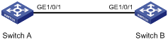
Configuring Switch A
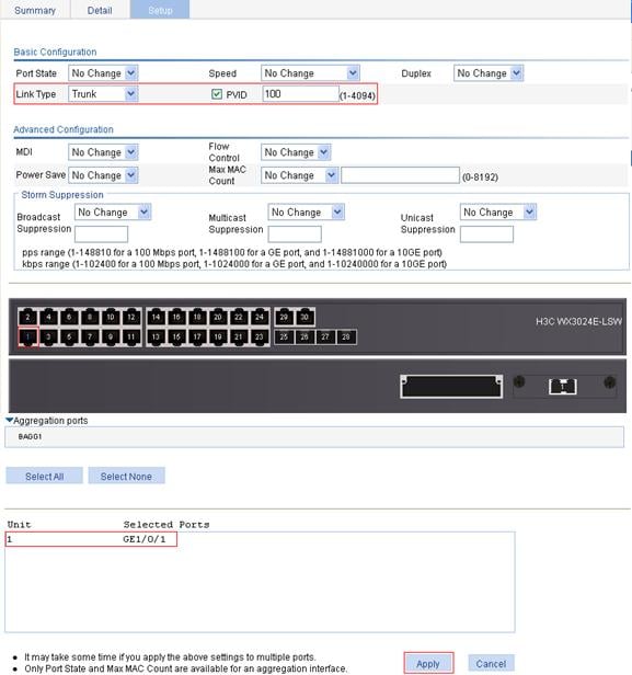
1. Configure GigabitEthernet 1/0/1 as a trunk port and configure VLAN 100 as its default VLAN:
a. Select Device > Port Management from the navigation tree.
b. Click the Setup tab.
c. Select Trunk from the Link Type list, select the PVID box and enter PVID 100, and select GigabitEthernet 1/0/1 on the chassis front device panel, as shown in Figure 7.
d. Click Apply.
Figure 7 Configure GigabitEthernet 1/0/1 as a trunk port and its PVID as 100
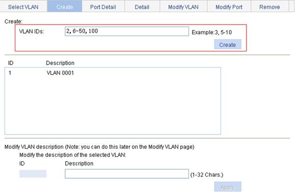
2. Create VLAN 2, VLAN 6 through VLAN 50, and VLAN 100:
a. Select Network > VLAN from the navigation tree.
b. Click the Create tab.
c. Enter VLAN IDs 2, 6-50, 100, as shown in Figure 8.
d. Click Apply.
Figure 8 Create VLAN 2, VLAN 6 through VLAN 50, and VLAN 100
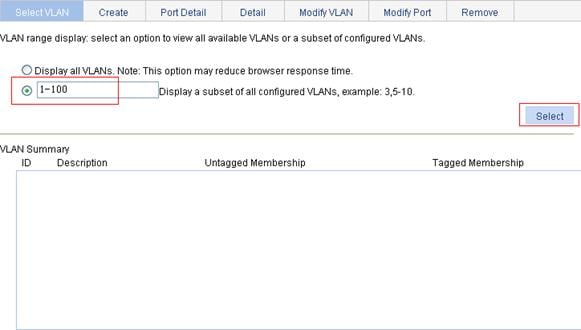
3. Assign GigabitEthernet 1/0/1 to VLAN 100 as an untagged member:
a. Click the Select VLAN tab.
b. Select the Display a subnet of all configured VLANs option and enter 1-100 in the field, as shown in Figure 9.
c. Click Select.
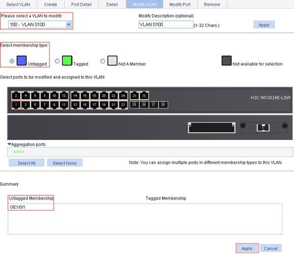
d. Click the Modify VLAN tab.
e. To assign GigabitEthernet 1/0/1 to VLAN 100 as an untagged member:
¡ Select 100 – VLAN 0100 from the Please select a VLAN to modify: list.
¡ Select the Untagged option.
¡ Select GigabitEthernet 1/0/1 on the chassis front device panel.
f. Click Apply to view the configuration progress in the popup dialog box.
g. After the configuration succeeds, close the dialog box.
Figure 10 Assign GigabitEthernet 1/0/1 to VLAN 100 as an untagged member
4. Assign GigabitEthernet 1/0/1 to VLAN 2, and VLAN 6 through VLAN 50 as a tagged member:
a. Click the Modify Port tab.
b. Select GigabitEthernet 1/0/1 on the chassis front device panel, select the Tagged option, and enter VLAN IDs 2, 6-50, as shown in Figure 11.
c. Click Apply to view the configuration progress in the popup dialog box.
d. After the configuration succeeds, close the dialog box.
Figure 11 Assign GigabitEthernet 1/0/1 to VLAN 2 and to VLANs 6 through 50 as a tagged member

Configuring Switch B
Configure Switch B as you configure Switch A.
Configuration guidelines
When you configure VLAN, follow these guidelines:
· VLAN 1 is the default VLAN, which can be neither created nor removed manually.
· Some VLANs are reserved for some special purposes. You can neither create nor remove them manually.
· Dynamic VLANs cannot be removed on the page for removing VLANs.
Overview
|
|
NOTE: For more information about VLANs, see H3C WX3000E Series Wireless Switches Switching Engine Configuration Guide. |
For hosts of different VLANs to communicate, you must use a router or Layer 3 switch to perform layer 3 forwarding. To achieve this, VLAN interfaces are used.
VLAN interfaces are virtual interfaces used for Layer 3 communication between different VLANs. They do not exist as physical entities on devices. For each VLAN, you can create one VLAN interface. You can assign the VLAN interface an IP address and specify it as the gateway of the VLAN to forward the traffic destined for an IP network segment different from that of the VLAN.
Creating a VLAN interface
When you create a VLAN interface, you can assign an IPv4 address and an IPv6 link-local address to the VLAN interface at the same time, or assign an address to it during modification.
To create a VLAN interface:
1. Select Network > VLAN Interface from the navigation tree.
2. Click the Create tab to enter the page for creating a VLAN interface, as shown in Figure 12.
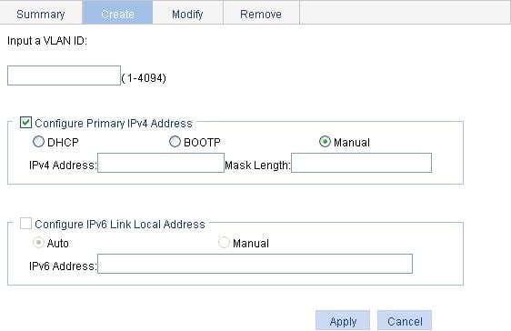
3. Create a VLAN interface as described in Table 5.
4. Click Apply.
|
Item |
Description |
||
|
Input a VLAN ID: |
Enter the ID of the VLAN interface to be created. Before creating a VLAN interface, make sure that the corresponding VLAN exists. |
||
|
Configure Primary IPv4 Address |
DHCP |
Configure the way in which the VLAN interface gets an IPv4 address. Allow the VLAN interface to obtain an IP address automatically by selecting the DHCP or BOOTP option, or manually assign the VLAN interface an IP address by selecting the Manual option. |
These items are available after you select the Configure Primary IPv4 Address option. |
|
BOOTP |
|||
|
Manual |
|||
|
IPv4 Address |
Configure an IPv4 address for the VLAN interface. This option is available after you select the Manual option. |
||
|
Mask Length |
Set the subnet mask length (or enter a mask in dotted decimal notation format). This option is available after you select the Manual option. |
||
|
Configure IPv6 Link Local Address |
Auto |
Configure the way in which the VLAN interface obtains an IPv6 link-local address. Select the Auto or Manual option: · Auto: The device automatically assigns a link-local address for the VLAN interface based on the link-local address prefix (FE80::/64) and the link-layer address of the VLAN interface. · Manual: Requires manual assignment. |
These items are available after you select the Configure IPv6 Link Local Address option. |
|
Manual |
|||
|
IPv6 Address |
Configure an IPv6 link-local address for the VLAN interface. This option is available after you select the Manual option. The prefix of the IPv6 link-local address you entered must be FE80::/64. |
||
Modifying a VLAN interface
By modifying a VLAN interface, you can assign an IPv4 address, an IPv6 link-local address, and an IPv6 site-local address, or global unicast address to the VLAN interface, or shut down or bring up the VLAN interface.
|
|
NOTE: · After you modify the IPv4 address and status or the IPv6 address and status, or add an IPv6 unicast address for a selected VLAN interface on the page for modifying VLAN interfaces, you need to click the correct Apply button to submit the modification. · After you change the IP address of the VLAN interface you are using to log in to the device, you will be disconnected from the device. You can use the changed IP address to re-log in. |
1. Select Network > VLAN Interface from the navigation tree.
2. Click the Modify tab to enter the page for modifying a VLAN interface, as shown in Figure 13.
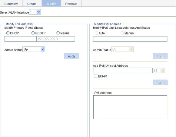
3. Modify a VLAN interface as described in Table 6.
4. Click Apply.
|
Item |
Description |
|
|
Select VLAN Interface |
Select the VLAN interface to be configured. The VLAN interfaces available for selection in the list are those created on the page for creating VLAN interfaces. |
|
|
Modify IPv4 Address |
DHCP |
Configure the way in which the VLAN interface gets an IPv4 address. Allow the VLAN interface to obtain an IP address automatically by selecting the DHCP or BOOTP option, or manually assign the VLAN interface an IP address by selecting the Manual option. In the latter case, you need to set the mask length or enter a mask in dotted decimal notation format. |
|
BOOTP |
||
|
Manual |
||
|
Admin Status |
Select Up or Down from the Admin Status list to bring up or shut down the selected VLAN interface. When the VLAN interface fails, you can shut down and then bring up the VLAN interface, which may restore it. By default, a VLAN interface is down if all Ethernet ports in the VLAN are down; otherwise, the VLAN interface is up.
· The current VLAN interface state in the Modify IPv4 Address and Modify IPv6 Address frames changes as the VLAN interface state is modified in the Admin Status list. · The state of each port in the VLAN is independent of the VLAN interface state. |
|
|
Modify IPv6 Address |
Auto |
Configure the way in which the VLAN interface obtains an IPv6 link-local address. Select the Auto or Manual option: · Auto: Indicates that the device automatically assigns a link-local address for the VLAN interface according to the link-local address prefix (FE80::/64) and the link-layer address of the VLAN interface. · Manual: Configures an IPv6 link-local address for the VLAN interface manually. |
|
Manual |
||
|
Admin Status |
Select Up or Down from the Admin Status list to bring up or shut down the selected VLAN interface. When the VLAN interface fails, you can shut down and then enable the VLAN interface, which may restore it. By default, a VLAN interface is down if all Ethernet ports in the VLAN are down; otherwise, the VLAN interface is up.
· The current VLAN interface state in the Modify IPv4 Address and Modify IPv6 Address frames changes as the VLAN interface state is modified in the Admin Status list. · The state of each port in the VLAN is independent of the VLAN interface state. |
|
|
Add IPv6 Unicast Address |
Assign an IPv6 site-local address or global unicast address to the VLAN interface. Enter an IPv6 address in the field and select a prefix length from the list. The prefix of the IPv6 address you entered in cannot be FE80::/10, the prefix of the link-local address. The prefix of the IPv6 site-local address you entered must be FEC0::/10. |
|
|
EUI-64 |
Specify to generate IPv6 site-local addresses or global unicast addresses in the EUI-64 format. If the EUI-64 option is not specified, manually configured IPv6 site-local addresses or global unicast addresses are used. |
|
Configuration guidelines
When you configure VLAN interfaces, follow these guidelines:
· A link-local address is automatically generated for an IPv6 VLAN interface after an IPv6 site-local address or global unicast address is configured for the VLAN interface. This generated link-local address is the same as the one generated in the Auto mode. If a manually assigned link-local address is available, the manually assigned one takes effect. After the manually assigned link-local address is removed, the automatically generated one takes effect.
· For an IPv6 VLAN interface whose IPv6 link-local address is generated automatically after you assign an IPv6 site-local address or global unicast address, removing the IPv6 site-local address or global unicast address also removes the generated IPv6 link-local address.
· For IPv6 link-local address configuration, manual assignment takes precedence over automatic generation. If you first adopt the manual assignment and then the automatic generation, the automatically generated link-local address will not take effect and the link-local address of the interface is still the manually assigned one. However, if you remove the manually assigned one, the one automatically generated takes effect.
Overview
A voice VLAN is dedicated to voice traffic. After assigning the ports connecting to voice devices to a voice VLAN, you can configure quality of service (QoS) parameters for the voice traffic, improving transmission priority and ensuring voice quality.
|
|
NOTE: For more information about voice VLANs, see H3C WX3000E Series Wireless Switches Switching Engine Configuration Guide. |
Recommended voice VLAN configuration procedures
Before configuring the voice VLAN, you must create the VLAN and configure the link type of each port to be assigned to the VLAN. As VLAN 1 is the system-default VLAN, you do not need to create it; however, you cannot configure it as the voice VLAN. For information about port link types, see the chapter “Port management configuration.”
Recommended configuration procedure for configuring voice VLAN on a port in automatic voice VLAN assignment mode
|
Step |
Remarks |
|
Optional Configure the voice VLAN to operate in security mode and configure the aging timer. |
|
|
Required Configure the voice VLAN assignment mode of a port as automatic and enable the voice VLAN function on the port. By default, the voice VLAN assignment mode of a port is automatic, and the voice VLAN function is disabled on a port. |
|
|
Optional The system supports up to 16 OUI addresses. By default, the system is configured with seven OUI addresses. |
Recommended configuration procedure for configuring voice VLAN on a port working in manual voice VLAN assignment mode
|
Step |
Remarks |
|
Optional Configure the voice VLAN to operate in security mode and configure the aging timer. |
|
|
2. Assigning the port to the voice VLAN |
Required After an access port is assigned to the voice VLAN, the voice VLAN automatically becomes the default VLAN of the access port. For more information, see the chapter “VLAN configuration.” |
|
3. Configuring the voice VLAN as the default VLAN of a hybrid or trunk port |
Optional This task is required if the incoming voice traffic is untagged and the link type of the receiving port is trunk or hybrid. If the incoming voice traffic is tagged, do not perform this task. For more information, see the chapter “Port management configuration.” |
|
Required Configure the voice VLAN assignment mode of a port as manual and enable voice VLAN on the port. By default, the voice VLAN assignment mode of a port is automatic, and voice VLAN is disabled on a port. |
|
|
Optional You can configure up to 16 OUI addresses. By default, the system is configured with the seven OUI addresses. |
Configuring voice VLAN globally
1. Select Network > Voice VLAN from the navigation tree.
2. Click the Setup tab to enter the page shown in Figure 14.
Figure 14 Configure voice VLAN
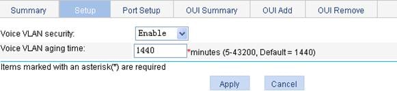
3. Configure the voice VLAN as described in Table 7.
4. Click Apply.
|
Item |
Description |
|
Voice VLAN security |
Select Enable or Disable from the list to enable or disable the voice VLAN security mode. By default, the voice VLANs operate in security mode. |
|
Voice VLAN aging time |
Set the voice VLAN aging timer. The voice VLAN aging timer setting only applies to a port in automatic voice VLAN assignment mode. The voice VLAN aging timer starts as soon as the port is assigned to the voice VLAN. If no voice packet has been received before the timer expires, the port is removed from the voice VLAN. |
Configuring voice VLAN on a port
1. Select Network > Voice VLAN from the navigation tree.
2. Click the Port Setup tab to enter the page shown in Figure 15.
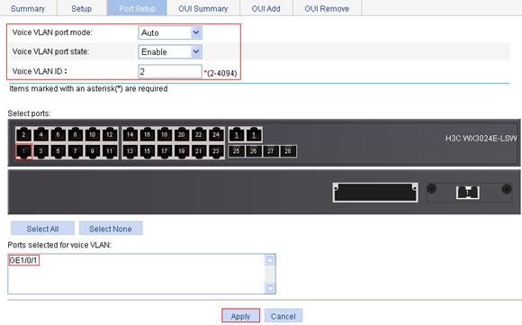
Figure 15 Configure voice VLAN on a port
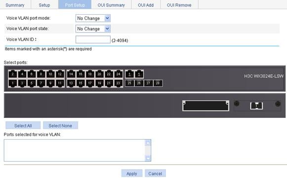
3. Configure voice VLAN on a port as described in Table 8.
4. Click Apply.
|
Item |
Description |
|
Voice VLAN port mode |
Set the voice VLAN assignment mode of a port to: · Auto—Automatic voice VLAN assignment mode · Manual—Manual voice VLAN assignment mode |
|
Voice VLAN port state |
Select Enable or Disable from the list to enable or disable the voice VLAN function on the port. |
|
Voice VLAN ID |
Set the voice VLAN ID of a port when the voice VLAN port state is set to Enable. |
|
Select Ports |
Select the port on the chassis front panel. You can select multiple ports to configure them in bulk. The numbers of the selected ports will be displayed in the Ports selected for voice VLAN field.
To set the voice VLAN assignment mode of a port to automatic, you must make sure that the link type of the port is trunk or hybrid, and that the port does not belong to the voice VLAN. |
Adding OUI addresses to the OUI list
1. Select Network > Voice VLAN from the navigation tree.
2. Click the OUI Add tab to enter the page shown in Figure 16.
Figure 16 Add OUI addresses to the OUI list
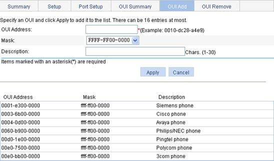
3. Add OUI addresses to the OUI list as described in Table 9.
4. Click Apply.
|
Item |
Description |
|
OUI Address |
Set the source MAC address of voice traffic. |
|
Mask |
Set the mask length of the source MAC address. |
|
Description |
Set the description of the OUI address entry. |
Example for configuring voice VLAN on a port in automatic voice VLAN assignment mode
Network requirements
As shown in Figure 17:
· Configure VLAN 2 as the voice VLAN allowing only voice traffic to pass through.
· The IP phone connected to hybrid port GigabitEthernet 1/0/1 sends untagged voice traffic.
· GigabitEthernet 1/0/1 operates in automatic VLAN assignment mode. Set the voice VLAN aging timer to 30 minutes.
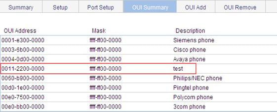
· Configure GigabitEthernet 1/0/1 to allow voice packets whose source MAC addresses match the OUI addresses specified by OUI address 0011-2200-0000 and mask ffff-ff00-0000. The description of the OUI address entry is test.
Configuration procedure
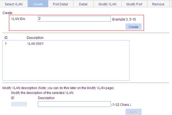
1. Create VLAN 2:
a. Select Network > VLAN from the navigation tree.
b. Click Create.
c. Enter VLAN ID 2, as shown in Figure 18.
d. Click Create.
2. Configure GigabitEthernet 1/0/1 as a hybrid port:
a. Select Device > Port Management from the navigation tree.
b. Click the Setup tab.
c. Select Hybrid from the Link Type list, and select GE1/0/1 from the chassis front panel, as shown in Figure 19.
d. Click Apply.
Figure 19 Configure GigabitEthernet 1/0/1 as a hybrid port
3. Configure the voice VLAN function globally:
a. Select Network > Voice VLAN from the navigation tree.
b. Click the Setup tab.
c. To configure the voice VLAN function globally:
¡ Select Enable from the Voice VLAN security list. (You can skip this step, because the voice VLAN security mode is enabled by default)
¡ Set the voice VLAN aging timer to 30 minutes.
d. Click Apply.
Figure 20 Configure the voice VLAN function globally
4. Configure voice VLAN on GigabitEthernet 1/0/1:
a. Click the Port Setup tab.
b. To configure voice VLAN on GigabitEthernet 1/0/1:
¡ Select Auto from the Voice VLAN port mode list.
¡ Select Enable from the Voice VLAN port state list.
¡ Enter voice VLAN ID 2.
¡ Select GE1/0/1 on the chassis front panel.
c. Click Apply.
Figure 21 Configure voice VLAN on GigabitEthernet 1/0/1
5. Add OUI addresses to the OUI list:
a. Click the OUI Add tab.
b. To add OUI addresses to the OUI list:
¡ Enter OUI address 0011-2200-0000.
¡ Select FFFF-FF00-0000 from the Mask list.
¡ Enter description string test.
c. Click Apply.
Figure 22 Add OUI addresses to the OUI list

Verifying the configuration
1. When the preceding configurations are completed, the OUI Summary tab is displayed by default, as shown in Figure 23. You can view the information about the newly-added OUI address.
Figure 23 Current OUI list of the device
2. Click the Summary tab to enter the page shown in Figure 24, where you can view the current voice VLAN information.
Figure 24 Current voice VLAN information

Example for configuring a voice VLAN on a port in manual voice VLAN assignment mode
Network requirements
As shown in Figure 25:
· Configure VLAN 2 as a voice VLAN that carries only voice traffic.
· The IP phone connected to hybrid port GigabitEthernet 1/0/1 sends untagged voice traffic.
· GigabitEthernet 1/0/1 operates in manual voice VLAN assignment mode and allows voice packets whose source MAC addresses match the OUI addresses specified by OUI address 0011-2200-0000 and mask ffff-ff00-0000 to pass through. The description of the OUI address entry is test.
Configuration procedure
1. Create VLAN 2:
a. Select Network > VLAN from the navigation tree.
b. Click the Create tab.
c. Enter 2 for VLAN IDs, as shown in Figure 26.
d. Click Create.
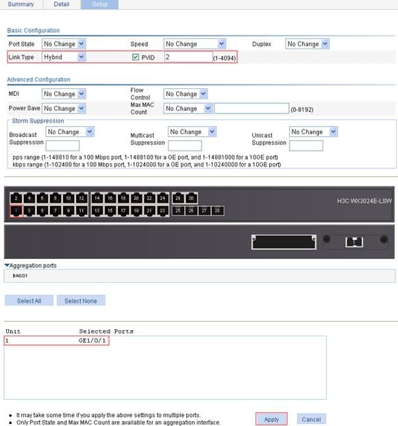
2. Configure GigabitEthernet 1/0/1 as a hybrid port and configure its default VLAN as VLAN 2:
a. Select Device > Port Management from the navigation tree.
b. Click the Setup tab.
c. To configure GigabitEthernet 1/0/1 as a hybrid port and configure its default VLAN as VLAN 2:
¡ Select Hybrid from the Link Type list.
¡ Select the PVID option and enter 2 in the field.
¡ Select GE1/0/1 from the chassis front panel.
d. Click Apply.
Figure 27 Configure GigabitEthernet 1/0/1 as a hybrid port
3. Assign GigabitEthernet 1/0/1 to VLAN 2 as an untagged member:
a. Select Network > VLAN from the navigation tree.
b. Click the Modify Port tab.
c. To assign GigabitEthernet 1/0/1 to VLAN 2 as an untagged member:
¡ Select GE1/0/1 from the chassis front panel.
¡ Select the Untagged option.
¡ Enter VLAN ID 2.
d. Click Apply to view the configuration progress in the popup dialog box.
e. After the configuration succeeds, close the dialog box.
Figure 28 Assign GigabitEthernet 1/0/1 to VLAN 2 as an untagged member
4. Configure voice VLAN on GigabitEthernet 1/0/1:
a. Select Network > Voice VLAN from the navigation tree.
b. Click the Port Setup tab.
c. To configure voice VLAN on GigabitEthernet 1/0/1:
¡ Select Manual from the Voice VLAN port mode list.
¡ Select Enable from the Voice VLAN port state list.
¡ Enter voice VLAN ID 2.
¡ Select GE1/0/1 on the chassis front panel.
d. Click Apply.
Figure 29 Configure voice VLAN on GigabitEthernet 1/0/1
5. Add OUI addresses to the OUI list:
a. Click the OUI Add tab.
b. Enter OUI address 0011-2200-0000, select FFFF-FF00-0000 as the mask, and enter description string test, as shown in Figure 30.
c. Click Apply.
Figure 30 Add OUI addresses to the OUI list
Verifying the configuration
1. When the preceding configurations are complete, the OUI Summary tab is displayed by default, as shown in Figure 31. You can view the information about the newly-added OUI address.
Figure 31 Current OUI list of the device

2. Click the Summary tab to enter the page shown in Figure 32, where you can view the current voice VLAN information.
Figure 32 Current voice VLAN information
Configuration guidelines
When you configure the voice VLAN function, follow these guidelines:
· To remove a VLAN functioning as a voice VLAN, disable its voice VLAN function first.
· In automatic voice VLAN assignment mode, a hybrid port can process only tagged voice traffic. However, the protocol-based VLAN function requires hybrid ports to process untagged traffic. If a VLAN is configured as the voice VLAN and a protocol-based VLAN at the same time, the protocol-based VLAN cannot be associated with the port.
· Only one VLAN is supported and only an existing static VLAN can be configured as the voice VLAN.
· If Link Aggregation Control Protocol (LACP) is enabled on a port, the voice VLAN function cannot be enabled on it.
· After you assign a port working in manual voice VLAN assignment mode to the voice VLAN, the voice VLAN takes effect.
|
|
NOTE: · MAC address configurations related to interfaces apply only to Layer 2 Ethernet interfaces. · This document covers only the management of static and dynamic MAC address entries, not multicast MAC address entries. |
Overview
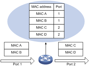
A device maintains a MAC address table for frame forwarding. Each entry in this table indicates the MAC address of a connected device, to which interface this device is connected and to which VLAN the interface belongs. A MAC address table consists of two types of entries: static and dynamic. Static entries are manually configured and never age out. Dynamic entries can be manually configured or dynamically learned and will age out.
When a frame arrives at a port, Port A for example, the switch performs the following tasks:
1. Checks the frame for the source MAC address (MAC-SOURCE for example).
2. Looks up the MAC address in the MAC address table.
3. If an entry is found, updates the entry. If no entry is found, adds an entry that contains the MAC address and the receiving port (Port A) to the MAC address table.
When receiving a frame destined for MAC-SOURCE, the device looks up the MAC address table and then forwards the frame from Port A.
|
|
NOTE: Dynamically learned MAC addresses cannot overwrite static MAC address entries, but the latter can overwrite the former. |
When forwarding a frame, the device adopts the following forwarding modes based on the MAC address table:
· Unicast mode: If an entry matching the destination MAC address exists, the device forwards the frame directly from the sending port recorded in the entry.
· Broadcast mode: If the device receives a frame with the destination address being all Fs, or no entry matches the destination MAC address, the device broadcasts the frame to all the ports except the receiving port.
Figure 33 MAC address table of the device
Configuring a MAC address entry
1. Select Network > MAC from the navigation tree . The system automatically displays the MAC tab, which shows all the MAC address entries on the device, as shown in Figure 34.
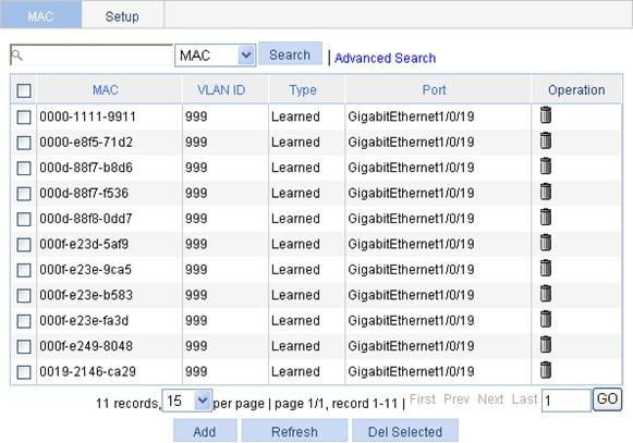
2. Click Add to enter the page for creating MAC address entries, as shown in Figure 35.
Figure 35 Create a MAC address entry
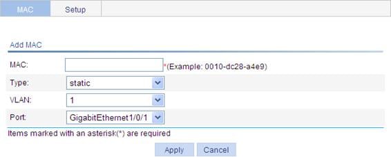
3. Configure the MAC address entry information as described in Table 10.
4. Click Apply.
|
Item |
Description |
|
MAC |
Set the MAC address to be added. |
|
Type |
Set the type of the MAC address entry: · static: Static MAC address entries that never age out. · dynamic: Dynamic MAC address entries that will age out. · blackhole: Blackhole MAC address entries that never age out.
The tab displays the following types of MAC address entries: · Config static: Static MAC address entries manually configured by the users. · Config dynamic: Dynamic MAC address entries manually configured by the users. · Blackhole: Blackhole MAC address entries. · Learned: Dynamic MAC address entries learned by the device. · Other: Other types of MAC address entries. |
|
VLAN |
Set the ID of the VLAN to which the MAC address belongs. |
|
Port |
Set the port to which the MAC address belongs. |
Setting the aging time of MAC address entries
1. Select Network > MAC from the navigation tree.
2. Click the Setup tab to enter the page for setting the MAC address entry aging time, as shown in Figure 36.
Figure 36 Set the aging time for MAC address entries
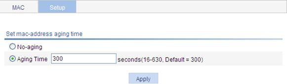
3. Set the aging time for MAC address entries as described in Table 11.
4. Click Apply.
|
Item |
Description |
|
No-aging |
Specify that the MAC address entry never ages out. |
|
Aging time |
Set the aging time for the MAC address entry |
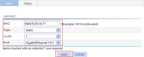
MAC address configuration example
Network requirements
Use the Web-based NMS to configure the MAC address table of the device. Add a static MAC address 00e0-fc35-dc71 under GigabitEthernet 1/0/1 in VLAN 1.
Configuration procedure
1. Create a static MAC address entry:
a. Select Network > MAC from the navigation tree to enter the MAC tab.
b. Click Add.
c. To configure MAC address entry information:
¡ Enter MAC address 00e0-fc35-dc71.
¡ Select static in the Type list.
¡ Select 1 in the VLAN list.
¡ Select GigabitEthernet1/0/1 in the Port list.
d. Click Apply.
Figure 37 Create a static MAC address entry
Overview
As a Layer 2 management protocol, the Spanning Tree Protocol (STP) eliminates Layer 2 loops by selectively blocking redundant links in a network, and in the mean time, allows for link redundancy.
Like many other protocols, STP evolves as the network grows. The later versions of STP are Rapid Spanning Tree Protocol (RSTP) and Multiple Spanning Tree Protocol (MSTP). This chapter describes the characteristics of STP, RSTP, and MSTP.
|
|
NOTE: For more information about MSTP, see H3C WX3000E Series Wireless Switches Switching Engine Configuration Guide. |
Recommended configuration procedure
|
Step |
Remarks |
|
Optional Configure the MST region-related parameters and VLAN-to-MSTI mappings. By default, the MST region-related parameters adopt the default values, and all VLANs in an MST region are mapped to MSTI 0. |
|
|
Required Enable STP globally and configure MSTP parameters. Whether STP is enabled globally depends on the device model; all MSTP parameters have default values. |
|
|
Optional Enable MSTP on a port and configure MSTP parameters. By default, MSTP is enabled on a port, and all MSTP parameters adopt the default values. |
|
|
Optional Display MSTP information of a port in MSTI 0, the MSTI to which the port belongs, and the path cost and priority of the port. |
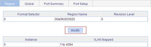
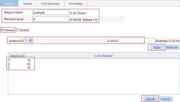
Configuring an MST region
1. Select Network > MSTP from the navigation tree to enter the page as shown in Figure 38.
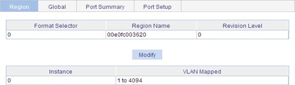
2. Click Modify to enter the page for configuring MST regions, as shown in Figure 39.
Figure 39 Configure an MST region
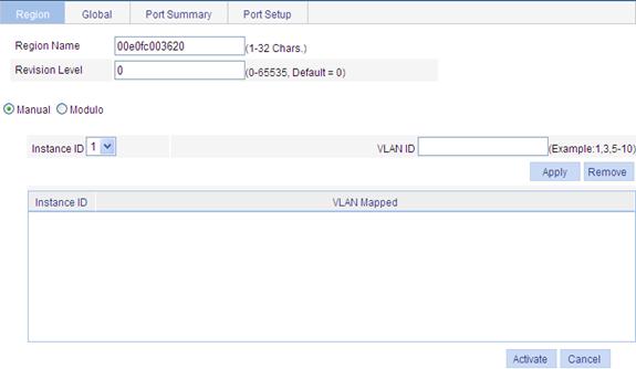
3. Configure the MSTP region information as described in Table 12.
4. Click Activate.
|
Item |
Description |
|
|
Region Name |
MST region name The MST region name is the bridge MAC address of the device by default. |
|
|
Revision Level |
Revision level of the MST region |
|
|
Manual |
Instance ID |
Manually add VLAN-to-MSTI mappings. Click Apply to add the VLAN-to-MSTI mapping entries to the list below. |
|
VLAN ID |
||
|
Modulo |
Modulo Value |
The device automatically maps 4094 VLANs to the corresponding MSTIs based on the modulo value. |
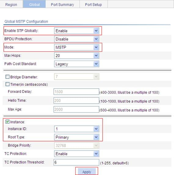
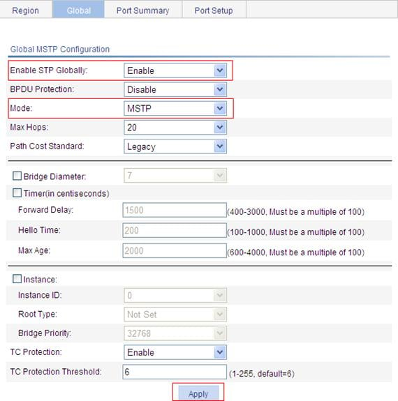
Configuring MSTP globally
1. Select Network > MSTP from the navigation tree.
2. Click the Global tab to enter the page for configuring MSTP globally, as shown in Figure 40.
Figure 40 Configure MSTP globally
3. Configure MSTP globally as described in Table 13.
4. Click Apply.
|
Item |
Description |
||
|
Enable STP Globally |
Select whether to enable STP globally. Other MSTP configurations take effect only after you enable STP globally. |
||
|
BPDU Guard |
Select whether to enable BPDU guard BPDU guard can protect the device from malicious BPDU attacks, making the network topology stable. |
||
|
Mode |
Set the working mode of STP, which can be STP, RSTP, or MSTP. · STP: Each port on a device sends out STP BPDUs. · RSTP: Each port on a device sends out RSTP BPDUs, and automatically migrates to STP-compatible mode when detecting that it is connected with a device running STP. · MSTP: Each port on a device sends out MSTP BPDUs, and automatically migrates to STP-compatible mode when detecting that it is connected with a device running STP. |
||
|
Max Hops |
Set the maximum number of hops in an MST region to restrict the region size. The setting can take effect only when it is configured on the regional root bridge. |
||
|
Path Cost Standard |
Specify the standard for path cost calculation. It can be Legacy, IEEE 802.1D-1998, or IEEE 802.1T. |
||
|
Bridge Diameter |
Any two stations in a switched network are interconnected through a specific path composed of a series of devices. The bridge diameter (or the network diameter) is the number of devices on the path composed of the most devices. After you set the network diameter, you cannot set the timers. Instead, the device automatically calculates the forward delay, hello time, and max age.
· The configured network diameter is effective for CIST only, not for MSTIs. · The bridge diameter cannot be configured together with the timers. |
||
|
Timers |
Forward Delay |
Set the delay for the root and designated ports to transit to the forwarding state. |
· The settings of hello time, forward delay and max age must meet a certain formula. Otherwise, the network topology will not be stable. H3C recommends you to set the network diameter and then have the device automatically calculate the forward delay, hello time, and max age. · The bridge diameter cannot be configured together with the timers. |
|
Hello Time |
Set the interval at which the device sends hello packets to the surrounding devices to make sure that the paths are fault-free. |
||
|
Max Age |
Set the maximum length of time a configuration BPDU can be held by the device. |
||
|
Instance |
Instance ID |
Set the role of the device in the MSTI or the bridge priority of the device, which is one of the factors deciding whether the device can be elected as the root bridge. Role of the device in the MSTI: · Not Set: Not set (you can set the bridge priority of the device when selecting this role) · Primary: Configure the device as the root bridge (you cannot set the bridge priority of the device when selecting this role) · Secondary: Configure the device as a secondary root bridge (you cannot set the bridge priority of the device when selecting this role). |
|
|
Root Type |
|||
|
Bridge Priority |
|||
|
tc-protection |
Select whether to enable TC-BPDU guard. When receiving topology change (TC) BPDUs, the device flushes its forwarding address entries. If someone forges TC-BPDUs to attack the device, the device will receive a large number of TC-BPDUs within a short time and frequently flushes its forwarding address entries. This affects network stability. With the TC-BPDU guard function, you can prevent frequent flushing of forwarding address entries.
H3C does not recommend you to disable this function. |
||
|
tc-protection threshold |
Set the maximum number of immediate forwarding address entry flushes the device can perform within a certain period of time after receiving the first TC-BPDU. |
||
Configuring MSTP on a port
1. Select Network > MSTP from the navigation tree.
2. Click the Port Setup tab to enter the page for configuring MSTP on ports, as shown in Figure 41.
Figure 41 MSTP configuration on a port
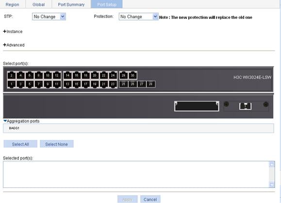
3. Configure the MSTP information as described in Table 14.
4. Click Apply.
Table 14 Configuration items of configuring MSTP on a port
|
Item |
Description |
|
|
STP |
Select whether to enable STP on the port. |
|
|
Protection |
Set the type of protection to be enabled on the port: · Not Set: No protection is enabled on the port. · Edged Port, Root Protection, Loop Protection: For more information, see Table 15. |
|
|
Instance |
Instance ID |
Set the priority and path cost of the port in the current MSTI. · The priority of a port is an important factor in determining whether the port can be elected as the root port of a device. If all other conditions are the same, the port with the highest priority will be elected as the root port. On an MSTP-enabled device, a port can have different priorities in different MSTIs, and the same port can play different roles in different MSTIs, so that data of different VLANs can be propagated along different physical paths, implementing per-VLAN load balancing. You can set port priority values based on the actual networking requirements. · Path cost is a parameter related to the rate of a port. On an MSTP-enabled device, a port can have different path costs in different MSTIs. Setting appropriate path costs allows VLAN traffic flows to be forwarded along different physical links, achieving VLAN-based load balancing. The device can automatically calculate the default path cost; alternatively, you can also manually configure path cost for ports. |
|
Port Priority |
||
|
Auto Path Cost |
||
|
Manual Path Cost |
||
|
Advanced |
Point to Point |
Specify whether the port is connected to a point-to-point link. · Auto: Automatically detects whether the link type of the port is point-to-point. · Force False: Specifies that the link type for the port is not point-to-point link. · Force True: Specifies that the link type for the port is point-to-point link.
If a port is configured as connecting to a point-to-point link, the setting takes effect for the port in all MSTIs. If the physical link to which the port connects is not a point-to-point link and you force it to be a point-to-point link by configuration, the configuration may incur a temporary loop. |
|
Transmit Limit |
Configure the maximum number of MSTP packets that can be sent during each Hello interval. The larger the transmit limit is, the more network resources will be occupied. H3C recommends that you use the default value. |
|
|
MSTP Mode |
Set whether the port migrates to the MSTP mode. In a switched network, if a port on an MSTP (or RSTP) device connects to a device running STP, this port will automatically migrate to the STP-compatible mode. After the device running STP is removed, the port on the MSTP (or RSTP) device may not be able to migrate automatically to the MSTP (or RSTP) mode, but will remain working in the STP-compatible mode. You can set this option to enable the port to automatically migrate to the MSTP (or RSTP) mode. |
|
|
Select port(s) |
Select one or multiple ports on which you want to configure MSTP on the chassis front panel. If aggregate interfaces are configured on the device, the page displays a list of aggregate interfaces below the chassis front panel. You can select aggregate interfaces from this list. |
|
|
Protection type |
Description |
|
Edged Port |
Set the port as an edge port. Some ports of access layer devices are directly connected to PCs or file servers, which cannot generate BPDUs. You can set these ports as edge ports to achieve fast transition for these ports. H3C recommends that you enable the BPDU guard function in conjunction with the edged port function to avoid network topology changes when the edge ports receive configuration BPDUs. |
|
Root Protection |
Enable the root guard function. Configuration errors or attacks may result in configuration BPDUs with their priorities higher than that of a root bridge, which causes a new root bridge to be elected and network topology change to occur. The root guard function is used to address such a problem. |
|
Loop Protection |
Enable the loop guard function. By keeping receiving BPDUs from the upstream device, a device can maintain the state of the root port and other blocked ports. These BPDUs may get lost because of network congestion or unidirectional link failures. The device will re-elect a root port, and blocked ports may transit to the forwarding state, causing loops in the network. The loop guard function is used to address such a problem. |
Displaying MSTP information of a port
1. Select Network > MSTP from the navigation tree.
2. Click the Port Summary tab.
3. Select a port (GigabitEthernet 1/0/16 for example) on the chassis front panel (If aggregate interfaces are configured on the device, the page displays a list of aggregate interfaces below the chassis front panel. You can select aggregate interfaces from this list). The lower part of the page displays the MSTP information of the port in MSTI 0 (when STP is enabled globally) or the STP status and statistics (when STP is not enabled globally), the MSTI to which the port belongs, and the path cost and priority of the port in the MSTI, as shown in Figure 42.
Figure 42 The Port Summary tab
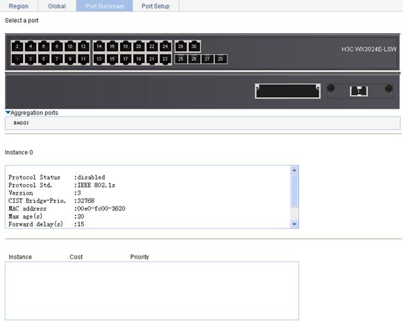
|
Field |
Description |
|
[FORWARDING] |
The port is in forwarding state: The port learns MAC addresses and forwards user traffic. |
|
[LEARNING] |
The port is in learning state: The port learns MAC addresses but does not forward user traffic. |
|
[DISCARDING] |
The port is in discarding state: The port does not learn MAC addresses or forward user traffic. |
|
[DOWN] |
The port is down. |
|
Port Protocol |
Whether STP is enabled on the port. |
|
Port Role |
The role of the port, which can be Alternate, Backup, Root, Designated, Master, or Disabled. |
|
Port Priority |
The priority of the port. |
|
Port Cost(Legacy) |
Path cost of the port. The field in the bracket indicates the standard used for port path cost calculation, which can be legacy, dot1d-1998, or dot1t. Config indicates the configured value, and Active indicates the actual value. |
|
Desg. Bridge/Port |
Designated bridge ID and port ID of the port The port ID displayed is insignificant for a port that does not support port priority. |
|
Port Edged |
Whether the port is an edge port: · Config indicates the configured value. · Active indicates the actual value. |
|
Point-to-point |
Whether the port is connected to a point-to-point link: · Config indicates the configured value. · Active indicates the actual value. |
|
Transmit Limit |
The maximum number of packets sent within each Hello time. |
|
Protection Type |
Protection type on the port,: · Root: Root guard · Loop: Loop guard · BPDU: BPDU guard · None: No protection |
|
MST BPDU Format |
Format of the MST BPDUs that the port can send, which can be legacy or 802.1s. Config indicates the configured value, and Active indicates the actual value. |
|
Port Config- Digest-Snooping |
Whether digest snooping is enabled on the port. |
|
Rapid transition |
Whether the current port rapidly transitions to the forwarding state. |
|
Num of Vlans Mapped |
Number of VLANs mapped to the current MSTI. |
|
PortTimes |
Major parameters for the port: · Hello: Hello timer · MaxAge: Max Age timer · FWDly: Forward delay timer · MsgAge: Message Age timer · Remain Hop: Remaining hops |
|
BPDU Sent |
Statistics on sent BPDUs. |
|
BPDU Received |
Statistics on received BPDUs. |
|
Protocol Status |
Whether MSTP is enabled. |
|
Protocol Std. |
MSTP standard. |
|
Version |
MSTP version. |
|
CIST Bridge-Prio. |
Priority of the current device in the CIST. |
|
MAC address |
MAC address of the current device. |
|
Max age(s) |
Maximum age of a configuration BPDU. |
|
Forward delay(s) |
Port state transition delay, in seconds. |
|
Hello time(s) |
Configuration BPDU transmission interval, in seconds. |
|
Max hops |
Maximum hops of the current MST region. |
MSTP configuration example
Network requirements
As shown in Figure 43, to enable packets of different VLANs to be forwarded along different MSTIs, perform the following configurations:
· All devices on the network are in the same MST region.
· Packets of VLAN 10, VLAN 20, VLAN 30, and VLAN 40 are forwarded along MSTI 1, MSTI 2, MSTI 3, and MSTI 0 respectively.
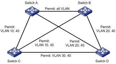
|
|
NOTE: "Permit:" next to a link in the figure is followed by the VLANs the packets of which are permitted to pass this link. |
Configuring Switch A
1. Configure an MST region:
a. Select Network > MSTP from the navigation tree to enter the default MSTP region page.
b. Click Modify as shown in Figure 44.
c. To configure the MSTP information:
¡ Set the region name to example.
¡ Set the revision level to 0.
¡ Select the Manual option.
¡ Select 1 from the Instance ID list.
¡ Set the VLAN ID to 10.
¡ Click Apply to map VLAN 10 to MSTI 1 and add the VLAN-to-MSTI mapping entry to the VLAN-to-MSTI mapping list.
¡ Repeat the previous steps to map VLAN 20 to MSTI 2 and VLAN 30 to MSTI 3 and add the VLAN-to-MSTI mapping entries to the VLAN-to-MSTI mapping list.
d. Click Activate.
Figure 45 Configure an MST region
2. Configure MSTP globally:
a. Select Network > MSTP from the navigation tree.
b. Click the Global tab.
c. To configure MSTP globally:
¡ Select Enable from the Enable STP Globally list.
¡ Select MSTP from the Mode list.
¡ Select the Instance option.
¡ Set the Instance ID field to 1.
¡ Set the Root Type field to Primary.
d. Click Apply.
Figure 46 Configure MSTP globally (on Switch A)
Configuring Switch B
1. Configure an MST region. (The procedure here is the same as that of configuring an MST region on Switch A.)
2. Configure MSTP globally:
a. Select Network > MSTP from the navigation tree.
b. Click the Global tab.
c. To configure MSTP globally:
¡ Select Enable from the Enable STP Globally list.
¡ Select MSTP from the Mode list.
¡ Select the Instance option.
¡ Set the Instance ID field to 2.
¡ Set the Root Type field to Primary.
d. Click Apply.
Configuring Switch C
1. Configure an MST region. (The procedure here is the same as that of configuring an MST region on Switch A.)
2. Configure MSTP globally:
a. Select Network > MSTP from the navigation tree.
b. Click the Global tab.
c. To configure MSTP globally:
¡ Select Enable from the Enable STP Globally list.
¡ Select MSTP from the Mode list.
¡ Select the Instance option.
¡ Set the Instance ID field to 3.
¡ Set the Root Type field to Primary.
d. Click Apply.
Configuring Switch D
1. Configure an MST region. The procedure is the same as that of configuring an MST region on Switch A.
2. Configure MSTP globally:
a. Select Network > MSTP from the navigation tree.
b. Click the Global tab.
c. Select Enable from the Enable STP Globally list, and select MSTP from the Mode list.
d. Click Apply.
Figure 47 Configure MSTP globally (on Switch D)
Configuration guidelines
When you configure MSTP, follow these guidelines:
· Two devices belong to the same MST region only if they are interconnected through physical links, and share the same region name, the same MSTP revision level, and the same VLAN-to-MSTI mappings.
· If two or more devices have been designated to be root bridges of the same spanning tree instance, MSTP will select the device with the lowest MAC address as the root bridge.
· If the device is not enabled with BPDU guard, when a boundary port receives a BPDU from another port, it transits into a non-boundary port. To restore its port role as a boundary port, you need to restart the port.
· Configure ports that are directly connected to terminals as boundary ports and enable BPDU guard for them. In this way, these ports can rapidly transit to the forwarding state, and the network security can be ensured.
Overview
Link aggregation aggregates multiple physical Ethernet ports into one logical link, also called an “aggregation group”.
Link aggregation allows you to increase bandwidth by distributing traffic across the member ports in the aggregation group. In addition, Link aggregation provides reliable connectivity because these member ports can dynamically back up each other.
|
|
NOTE: For more information about link aggregation and link aggregation control protocol (LACP), see H3C WX3000E Series Wireless Switches Switching Engine Configuration Guide. |
Recommended configuration procedures
Recommended static aggregation group configuration procedure
|
Step |
Remarks |
|
Required Create a static aggregate interface and configure member ports for the static aggregation group automatically created by the system when you create the aggregate interface. By default, no link aggregation group exists. |
|
|
Optional Perform this task to view detailed information of an existing aggregation group. |
Recommended dynamic aggregation group configuration procedure
|
Step |
Remarks |
|
Required Create a dynamic aggregate interface and configure member ports for the dynamic aggregation group automatically created by the system when you create the aggregate interface. LACP is enabled automatically on all the member ports. By default, no link aggregation group exists. |
|
|
Optional Perform this task to view detailed information of an existing aggregation group. |
|
|
Optional Perform the task to set LACP priority for the local system and link aggregation member ports. Changes of LACP priorities affect the Selected/Unselected state of link aggregation member ports. The default port LACP priority and system LACP priority are both 32768. |
|
|
Optional Perform the task to view detailed information of LACP-enabled ports and the corresponding remote (partner) ports. |
Creating a link aggregation group
1. Select Network > Link Aggregation from the navigation tree.
2. Click the Create tab to enter the page as shown in Figure 48.
Figure 48 Create a link aggregation group
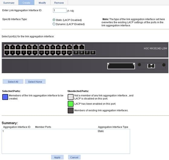
3. Configure the link aggregation group information as described in Table 17.
4. Click Apply.
|
Item |
Description |
|
Enter Link Aggregation Interface ID |
Assign an ID to the link aggregation group to be created. You can view the result in the Summary list box at the bottom of the page. |
|
Specify Interface Type |
Set the type of the link aggregation interface to be created: · Static (LACP Disabled) · Dynamic (LACP Enabled) |
|
Select port(s) for the link aggregation interface |
Select one or multiple ports to be assigned to the link aggregation group from the chassis front panel. You can view the result in the Summary list box at the bottom of the page. |
Displaying information of an aggregate interface
1. Select Network > Link Aggregation from the navigation tree.
The Summary tab is displayed by default, as shown in Figure 49. The list on the upper part of the page displays information about all the aggregate interfaces.
2. Select an aggregate interface from the list to display the detailed information about the member ports of the corresponding link aggregation group on the lower part of the page, as shown in Figure 49.
Figure 49 Display information of an aggregate interface
|
Field |
Description |
|
Aggregation interface |
Type and ID of the aggregate interface. Bridge-Aggregation indicates a Layer 2 aggregate interface. |
|
Link Type |
Type of the aggregate interface, which can be static or dynamic. |
|
Partner ID |
ID of the remote device, including its LACP priority and MAC address. |
|
Selected Ports |
Number of Selected ports in each link aggregation group (Only Selected ports can transmit and receive user data). |
|
Standby Ports |
Number of Unselected ports in each link aggregation group (Unselected ports cannot transmit or receive user data). |
|
Member Port |
A member port of the link aggregation group corresponding to the selected aggregate interface. |
|
State |
Select state of a member port, Selected or Unselected. |
|
Reason for being Unselected |
Reason why the state of a member port is Unselected. For a selected member port, this field is displayed as “-”. |
Setting LACP priority
1. Select Network > LACP from the navigation tree.
2. Click the Setup tab to enter the page shown in Figure 50.
3. Modify the LACP priority in the Select LACP enabled port(s) parameters field as described in Table 19.
4. Click Apply.
|
Item |
Description |
|
Port Priority |
Set a port LACP priority. |
|
Select port(s) to apply Port Priority |
Select the ports where the port LACP priority you set will apply on the chassis front panel. (You can set LACP priority not only on LACP-enabled ports but also on LACP-disabled ports.) |
|
System Priority |
Set the LACP priority of the local system. |
Displaying information of LACP-enabled ports
1. Select Network > LACP from the navigation tree.
The Summary tab is displayed by default, as shown in Figure 51. The upper part of the page displays a list of all LACP-enabled ports on the device and information about them.
2. Select an entry.
3. Click View Details to display detailed information about the peer port on the lower part of the page.
Figure 51 Display the information of LACP-enabled ports
Table 20 Field description in the LACP-enabled port summary table
|
Field |
Description |
|
Port |
Port where LACP is enabled. |
|
LACP State |
State of LACP on the port. |
|
Port Priority |
LACP priority of the port. |
|
State |
Active state of the port. If a port is selected, its state is active and the ID of the aggregation group it belongs to will be displayed. |
|
Inactive Reason |
Reason code indicating why a port is inactive (or Unselected) for receiving/transmitting user data. For the meanings of the reason codes, see the bottom of the page shown in Figure 51. |
|
Partner Port |
Name of the peer port. |
|
Partner Port State |
State information of the peer port, represented by letters A through H. · A indicates that LACP is enabled. · B indicates that LACP short timeout has occurred. If B does not appear, it indicates that LACP long timeout has occurred. · C indicates that the link is considered aggregatable by the sending system. · D indicates that the link is considered as synchronized by the sending system. · E indicates that the sending system considers that collection of incoming frames is enabled on the link. · F indicates that the sending system considers that distribution of outgoing frames is enabled on the link. · G indicates that the receive state machine of the sending system is using the default operational partner information. · H indicates that the receive state machine of the sending system is in the expired state. |
|
Oper Key |
Operational key of the local port. |
Table 21 Field description in the Partner Port Details table
|
Field |
Description |
|
Unit |
Number of the remote system. |
|
Port |
Name of the remote port. |
|
Partner ID |
LACP priority and MAC address of the remote system. |
|
Partner Port Priority |
LACP priority of the remote port. |
|
Partner Oper Key |
Operational key of the remote port. |
Link aggregation and LACP configuration example
Network requirements
As shown in Figure 52, aggregate the ports on each device to form a link aggregation group, balancing incoming/outgoing traffic across the member ports.
You can create a static or dynamic link aggregation group to achieve load balancing.
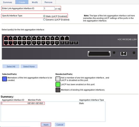
Approach 1: Creating a static link aggregation group
1. Create static link aggregation group 1:
a. Select Network > Link Aggregation from the navigation tree.
b. Click the Create tab.
c. To configure static link aggregation group 1:
¡ Set the link aggregation interface ID to 1.
¡ Select the Static (LACP Disabled) option for the aggregate interface type.
¡ Select GE1/0/1, GE1/0/2, and GE1/0/3 on the chassis front panel.
d. Click Apply.
Figure 53 Create static link aggregation group 1
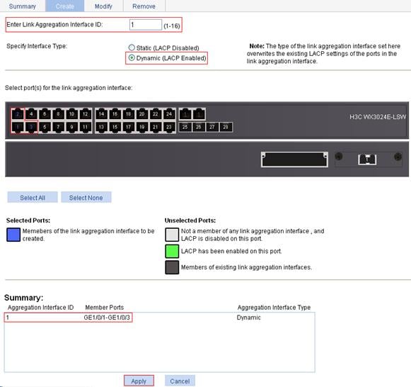
Approach 2: Creating a dynamic link aggregation group
1. Create dynamic link aggregation group 1:
a. Select Network > Link Aggregation from the navigation tree.
b. Click the Create tab.
c. To configure dynamic link aggregation group 1:
¡ Set the link aggregation interface ID to 1.
¡ Select the Dynamic (LACP Enabled) option for aggregate interface type.
¡ Select GE1/0/1, GE1/0/2, and GE1/0/3 on the chassis front panel.
d. Click Apply.
Figure 54 Create dynamic link aggregation group 1
Configuration guidelines
When you configure a link aggregation group, follow these guidelines:
· In an aggregation group, the port to be a Selected port must be the same as the reference port in port attributes, and class-two configurations. To keep these configurations consistent, you should configure the port manually.
· Reference port: Select a port as the reference port from the ports that are in up state and with the same class-two configurations as the corresponding aggregate interface. The selection is performed in the following order: full duplex/high speed, full duplex/low speed, half duplex/high speed, and half duplex/low speed, with full duplex/high speed being the most preferred. If two ports with the same duplex mode/speed pair are present, the one with the lower port number wins.
· Port attribute configuration includes the configuration of the port rate, duplex mode, and link state.
· For more information about class-two configurations, see H3C WX3000E Series Wireless Switches Switching Engine Configuration Guide.
· To guarantee a successful static aggregation, make sure that the ports at the two ends of each link to be aggregated are consistent in Selected/Unselected state. To guarantee a successful dynamic aggregation, make sure that the peer ports of the ports aggregated at one end are also aggregated. The two ends can automatically negotiate the Selected state of the ports.
· These types of ports cannot be assigned to Layer 2 aggregate groups: MAC address authentication-enabled ports, port security-enabled ports, packet filtering-enabled ports, Ethernet frame filtering-enabled ports, IP source guard-enabled ports, and 802.1X-enabled ports.
· H3C does not recommend you to assign the reflector port of a port mirroring group to an aggregation group. For more information about reflector ports, see the chapter “Port mirroring configuration.”
· Removing a Layer 2 aggregate interface also removes the corresponding aggregation group. Meanwhile, the member ports of the aggregation group, if any, leave the aggregation group.
· When a load-sharing aggregation group becomes a non-load-sharing aggregation group because of insufficient load sharing resources, one of the following problems may have occurred: The number of Selected ports of the actor is inconsistent with that of the partner, which may result in incorrect traffic forwarding; the peer port of a Selected port is an Unselected port, which may result anomalies in upper-layer protocol and traffic forwarding. You should fully consider the situation when making configuration.
LLDP configuration
Overview
In a heterogeneous network, it is important that different types of network devices from different vendors can discover one other and exchange configuration for interoperability and management sake. A standard configuration exchange platform was created.
The IETF drafted the Link Layer Discovery Protocol (LLDP) in IEEE 802.1AB. The protocol operates on the data link layer to exchange device information between directly connected devices. With LLDP, a device sends local device information as TLV (type, length, and value) triplets in LLDP Data Units (LLDPDUs) to the directly connected devices, and at the same time, stores the device information received in LLDPDUs sent from the LLDP neighbors in a standard management information base (MIB). It allows a network management system to fast detect Layer-2 network topology change and identify what the change is.
|
|
NOTE: For more information about LLDP, see H3C WX3000E Series Wireless Switches Switching Engine Configuration Guide. |
Recommended configuration procedure
|
Step |
Remarks |
|
Optional By default, LLDP is enabled on ports. Make sure that LLDP is also enabled globally, because LLDP can work on a port only when it is enabled both globally and on the port. |
|
|
Optional LLDP settings include LLDP operating mode, packet encapsulation, CDP compatibility, device information polling, trapping, and advertised TLVs. By default: · The LLDP operating mode is TxRx. · The encapsulation format is Ethernet II. · CDP compatibility is disabled. · Device information polling and trapping are disabled. · All TLVs except the Location Identification TLV are advertised. |
|
|
Required By default, global LLDP is disabled. To enable LLDP to work on a port, enable LLDP both globally and on the port. |
|
|
Optional You can display the local LLDP information, neighbor information, statistics, and status information of a port, where · The local LLDP information refers to the TLVs to be advertised by the local device to neighbors. · The neighbor information refers to the TLVs received from neighbors. |
|
|
Optional You can display the local global LLDP information and statistics. |
|
|
Optional You can display the LLDP information received from LLDP neighbors. |
Enabling LLDP on ports
1. Select Network > LLDP from the navigation tree to enter the Port Setup tab, as shown in Figure 55.
This tab displays the enabling status and operating mode of LLDP on a port.
2. Select one or more ports.
3. Click Enable beneath the port list to enable LLDP on them. To disable LLDP on a port, select the port and click Disable.
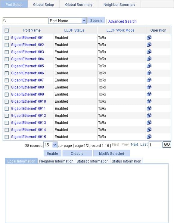
Configuring LLDP settings on ports
You can configure LLDP settings on ports individually or in batch.
Configuring LLDP settings on ports individually
1. Select Network > LLDP from the navigation tree to enter the Port Setup tab, as shown in Figure 55.
2. Click the ![]() icon for the port you are configuring.
icon for the port you are configuring.
On the page displayed as shown in Figure 56, you can modify or view the LLDP settings of the port.
Figure 56 The page for modifying LLDP settings on a port
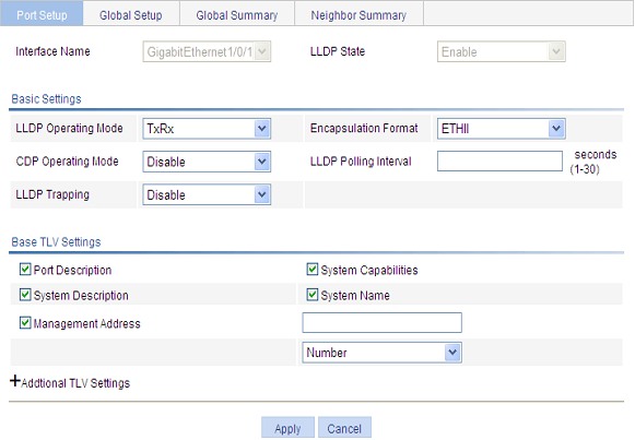
3. Configure LLDP settings on the port as described in Table 22.
4. Click Apply.
|
Item |
Description |
|
|
Interface Name |
Display the name of the port or ports you are configuring. |
|
|
DLDP State |
Display the LLDP enabling status on the port you are configuring. This field is not available when you batch-configure ports. |
|
|
Basic Settings |
LLDP Operating Mode |
Set the LLDP operating mode on the port or ports you are configuring. Available options include: · TxRx: Sends and receives LLDPDUs. · Tx: Sends but not receives LLDPDUs. · Rx: Receives but not sends LLDPDUs. · Disable: Neither sends nor receives LLDPDUs. |
|
Encapsulation Format |
Set the encapsulation for LLDPDUs. Available options include: · ETHII: Encapsulates outgoing LLDPDUs in Ethernet II frames and processes an incoming LLDPDU only if its encapsulation is Ethernet II. · SNAP: Encapsulates outgoing LLDPDUs in Ethernet II frames and processes an incoming LLDPDU only if its encapsulation is Ethernet II.
LLDP-CDP PDUs use only SNAP encapsulation. |
|
|
CDP Operating Mode |
Set the CDP compatibility of LLDP. Available options include: · Disable: Neither sends nor receives CDPDUs. · TxRx: Sends and receives CDPDUs
To enable LLDP to be compatible with CDP on the port, you must enable CDP compatibility on the Global Setup tab and set the CDP operating mode on the port to TxRx. |
|
|
LLDP Polling Interval |
Enable LLDP polling and set the polling interval. If no polling interval is set, LLDP polling is disabled. With the polling mechanism, LLDP periodically detects local configuration changes. If a configuration change is detected, an LLDPDU is sent to inform the LLDP neighbors of the change. |
|
|
LLDP Trapping |
Set the enable status of the LLDP trapping function on the port or ports. LLDP trapping is used to report to the network management station critical events such as new neighbor devices detected and link failures.
To avoid excessive traps from being sent when topology is instable, you can tune the minimum trap transit interval on the Global Setup tab. |
|
|
Base TLV Settings |
Port Description |
Select to include the port description TLV in transmitted LLDPDUs. |
|
System Capabilities |
Select to include the system capabilities TLV in transmitted LLDPDUs. |
|
|
System Description |
Select to include the system description TLV in transmitted LLDPDUs. |
|
|
System Name |
Select to include the system name TLV in transmitted LLDPDUs. |
|
|
Management Address |
Select to include the management address TLV in transmitted LLDPDUs and in addition, set the management address and its format (a numeric or character string in the TLV). If no management address is specified, the main IP address of the lowest VLAN carried on the port is used. If no main IP address is assigned to the VLAN, 127.0.0.1 is used. |
|
|
DOT1 TLV Setting |
Port VLAN ID |
Select to include the PVID TLV in transmitted LLDPDUs. |
|
Protocol VLAN ID |
Select to include port and protocol VLAN ID TLVs in transmitted LLDPDUs and specify the VLAN IDs to be advertised. If no VLAN is specified, the lowest protocol VLAN ID is transmitted. |
|
|
VLAN Name |
Select to include VLAN name TLVs in transmitted LLDPDUs and specify the VLAN IDs to be advertised. If no VLAN is specified, the lowest VLAN carried on the port is advertised. |
|
|
DOT3 TLV Setting |
Link Aggregation |
Select to include the link aggregation TLV in transmitted LLDPDUs. |
|
MAC/PHY Configuration/Status |
Select to include the MAC/PHY configuration/status TLV in transmitted LLDPDUs. |
|
|
Maximum Frame Size |
Select to include the maximum frame size TLV in transmitted LLDPDUs. |
|
|
Power via MDI |
Select to include the power via MDI TLV in transmitted LLDPDUs. |
|
|
MED TLV Setting |
LLDP-MED Capabilities |
Select to include the LLDP-MED capabilities TLV in transmitted LLDPDUs. |
|
Inventory |
Select to include the hardware revision TLV, firmware revision TLV, software revision TLV, serial number TLV, manufacturer name TLV, model name TLV and asset ID TLV in transmitted LLDPDUs. |
|
|
Network Policy |
Select to include the network policy TLV in transmitted LLDPDUs. |
|
|
Extended Power-via-MDI Capability |
Select to include the extended power-via-MDI TLV in transmitted LLDPDUs. |
|
|
Emergency Number |
Select to encode the emergency call number in the location identification TLV in transmitted LLDPDUs and set the emergency call number. |
|
|
Address |
Select Address to encode the civic address information of the network connectivity device in the location identification TLV in transmitted LLDPDUs. In addition, set the device type, which can be a DHCP server, switch or LLDP-MED endpoint, country code, and network device address. When you configure the network device address, select the address information type from the list, enter the address information in the field below and click Add next to the field to add the information to the address information list below. To remove an address information entry, select the entry from the list, and click Delete. The civic address information can include language, province/state, country, city, street, house number, name, postal/zip code, room number, post office box, and if necessary, additional information. |
|
|
Network Device Address |
||
Configuring LLDP settings on ports in batch
1. Select Network > LLDP from the navigation tree to enter the Port Setup tab, as shown in Figure 55.
2. Select one or more ports.
3. Click Modify Selected. The page shown in Figure 57 appears.
Figure 57 The page for modifying LLDP settings on ports in batch
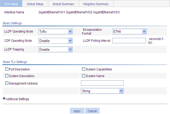
4. Configure LLDP parameters for the selected ports as described in Table 22.
Configuring global LLDP setup
1. Select Network > LLDP from the navigation tree.
2. Click the Global Setup tab to enter the page shown in Figure 58.
Figure 58 The Global Setup tab
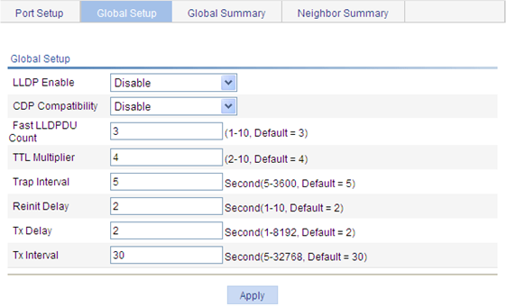
3. Configure the global LLDP setup parameters as described in Table 23.
4. Click Apply.
|
Item |
Description |
|
LLDP Enable |
Select from the list to enable or disable global LLDP. |
|
CDP Compatibility |
Select from the list to enable or disable CDP compatibility of LLDP.
· To enable LLDP to be compatible with CDP on a port, you must set the CDP work mode (or the CDP operating mode) on the port to TxRx in addition to enabling CDP compatibility on the Global Setup tab. · As the maximum TTL allowed by CDP is 255 seconds, you must make sure that the product of the TTL multiplier and the LLDPDU transmit interval is less than 255 seconds for CDP-compatible LLDP to work properly with Cisco IP phones. |
|
Fast LLDPDU Count |
Set the number of LLDPDUs sent each time fast LLDPDU transmission is triggered. |
|
TTL Multiplier |
Set the TTL multiplier. The TTL TLV carried in an LLDPDU determines how long the device information carried in the LLDPDU can be saved on a recipient device. You can configure the TTL of locally sent LLDPDUs to determine how long information about the local device can be saved on a neighbor device by setting the TTL multiplier. The TTL is expressed as TTL multiplier × LLDPDU transit interval.
· If the product of the TTL multiplier and the LLDPDU transmit interval is greater than 65535, the TTL carried in transmitted LLDPDUs takes 65535 seconds. · As the maximum TTL allowed by CDP is 255 seconds, you must make sure that the product of the TTL multiplier and the LLDPDU transmit interval is less than 255 seconds for CDP-compatible LLDP to work properly with Cisco IP phones. |
|
Trap Interval |
Set the minimum interval for sending traps. With the LLDP trapping function enabled on a port, traps are sent out the port to advertise the topology changes detected over the trap interval to neighbors. By tuning this interval, you can prevent excessive traps from being sent when topology is instable. |
|
Reinit Delay |
Set initialization delay for LLDP-enabled ports. Each time the LLDP operating mode of a port changes, its LLDP protocol state machine re-initializes. To prevent LLDP from being initialized too frequently at times of frequent operating mode change, initialization delay is introduced. With this delay mechanism, a port must wait for the specified interval before it can initialize LLDP after the LLDP operating mode changes. |
|
Tx Delay |
Set LLDPDU transmit delay. With LLDP enabled, a port advertises LLDPDUs to its neighbors both periodically and when the local configuration changes. To avoid excessive number of LLDPDUs caused by frequent local configuration changes, an LLDPDU transmit delay is introduced. After sending an LLDPDU, the port must wait for the specified interval before it can send another one.
LLDPDU transmit delay must be less than the TTL to make sure that the LLDP neighbors can receive LLDPDUs to update information about the device you are configuring before it is aged out. |
|
Tx Interval |
Set the LLDPDU transmit interval.
If the product of the TTL multiplier and the LLDPDU transmit interval is greater than 65535, the TTL carried in transmitted LLDPDUs takes 65535 seconds. The likelihood exists that the LLDPDU transmit interval is greater than TTL. You should avoid the situation, because the LLDP neighbors will fail to receive LLDPDUs to update information about the device you are configuring before it is aged out. |
Displaying LLDP information for a port
1. Select Network > LLDP from the navigation tree to enter the Port Setup tab, as shown in Figure 55.
2. In the port list click a port name to display its LLDP information at the lower half of the page. The Local Information tab is displayed by default, as shown in Figure 59.
Figure 59 The Local Information tab
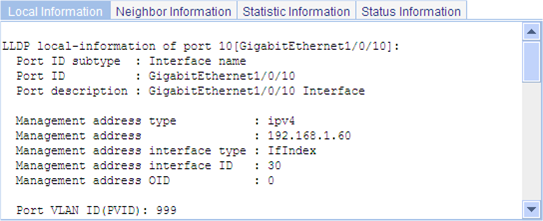
|
Field |
Description |
|
Port ID subtype |
Port ID type: · Interface alias · Port component · MAC address · Network address · Interface name · Agent circuit ID · Locally assigned, or the local configuration |
|
Power port class |
The power over Ethernet port class: · PSE, indicating a power supply device · PD: indicating a powered device
This field is available depending on your device mode. |
|
Port power classification |
Port power classification of the PD: · Unknown · Class0 · Class1 · Class2 · Class3 · Class4 |
|
Media policy type |
Media policy type: · Unknown · Voice · Voice signaling · Guest voice · Guest voice signaling · Soft phone voice · Videoconferencing · Streaming video · Video signaling |
|
PoE PSE power source |
The type of PSE power source advertised by the local device: · Primary · Backup |
|
Port PSE priority |
PSE priority of the port: · Unknown—The PSE priority of the port is unknown. · Critical—Priority level 1. · High—Priority level 2. · Low—Priority level 3. |
3. Click the Neighbor Information tab to view the LLDP neighbor information as shown in Figure 60.
Figure 60 The Neighbor Information tab
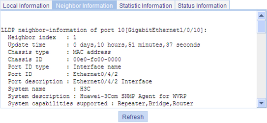
Table 25 Field description
|
Field |
Description |
|
Chassis type |
Chassis ID type: · Chassis component · Interface alias · Port component · MAC address · Network address · Interface name · Locally assigned, or the local configuration |
|
Chassis ID |
Chassis ID depending on the chassis type, which can be a MAC address of the device |
|
Port ID type |
Port ID type: · Interface alias · Port component · MAC address · Network address · Interface name · Agent circuit ID · Locally assigned, or the local configuration |
|
Port ID |
The port ID value. |
|
System capabilities supported |
The primary network function of the system: · Repeater · Bridge · Router |
|
System capabilities enabled |
The network function enabled on the system: · Repeater · Bridge · Router |
|
Auto-negotiation supported |
The support of the neighbor for auto negotiation |
|
Auto-negotiation enabled |
The enable status of auto negotiation on the neighbor. |
|
OperMau |
Current speed and duplex mode of the neighbor |
|
Link aggregation supported |
· The support of the neighbor for link aggregation |
|
Link aggregation enabled |
· The enable status of link aggregation on the neighbor |
|
Aggregation port ID |
· Link aggregation group ID. It is 0 if the neighbor port is not assigned to any link aggregation group. |
|
Maximum frame Size |
· The maximum frame size supported on the neighbor port. |
|
Device class |
MED device type: · Connectivity device: An intermediate device that provide network connectivity. · Class I: a generic endpoint device. All endpoints that require the discovery service of LLDP belong to this category. · Class II: A media endpoint device. The class II endpoint devices support the media stream capabilities in addition to the capabilities of generic endpoint devices. · Class III: A communication endpoint device. The class III endpoint devices directly support end users of the IP communication system. Providing all capabilities of generic and media endpoint devices, Class III endpoint devices are used directly by end users. |
|
Media policy type |
Media policy type: · Unknown · Voice · Voice signaling · Guest voice · Guest voice signaling · Soft phone voice · Videoconferencing · Streaming video · Video signaling |
|
Unknown Policy |
Indicates whether the media policy type is unknown. |
|
VLAN tagged |
Indicates whether packets of the media VLAN are tagged. |
|
Media policy VlanID |
ID of the media VLAN. |
|
Media policy L2 priority |
Layer 2 priority. |
|
Media policy Dscp |
DSCP precedence. |
|
HardwareRev |
Hardware version of the neighbor. |
|
FirmwareRev |
Firmware version of the neighbor. |
|
SoftwareRev |
Software version of the neighbor. |
|
SerialNum |
The serial number advertised by the neighbor. |
|
Manufacturer name |
The manufacturer name advertised by the neighbor. |
|
Model name |
The model name advertised by the neighbor. |
|
Asset tracking identifier |
Asset ID advertised by the neighbor. This ID is used for the purpose of inventory management and asset tracking. |
|
PoE PSE power source |
Type of PSE power source advertised by the neighbor: · Primary · Backup |
|
Port PSE priority |
PSE priority of the port: · Unknown—The PSE priority of the port is unknown. · Critical—Priority level 1. · High—Priority level 2. · Low—Priority level 3. |
4. Click the Statistic Information tab to view the LLDP statistics of the port, as shown in Figure 61.
Figure 61 The Statistic Information tab
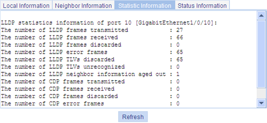
5. Click the Status Information tab to view the LLDP status information, as shown in Figure 62.
Figure 62 The Status Information tab
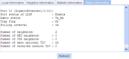
Displaying global LLDP information
1. Select Network > LLDP from the navigation tree.
2. Click the Global Summary tab to display global local LLDP information and statistics, as shown in Figure 63.
Figure 63 The Global Summary tab
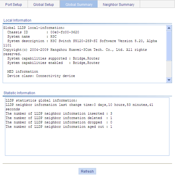
Table 26 Field description
|
Field |
Description |
|
Chassis ID |
The local chassis ID depending on the chassis type defined. |
|
System capabilities supported |
The primary network function advertised by the local device: · Repeater · Bridge · Router |
|
System capabilities enabled |
The enabled network function advertised by the local device: · Repeater · Bridge · Router |
|
Device class |
The device class advertised by the local device: · Connectivity device: An intermediate device that provide network connectivity. · Class I: a generic endpoint device. All endpoints that require the discovery service of LLDP belong to this category. · Class II: A media endpoint device. The class II endpoint devices support the media stream capabilities in addition to the capabilities of generic endpoint devices. · Class III: A communication endpoint device. The class III endpoint devices directly support end users of the IP communication system. Providing all capabilities of generic and media endpoint devices, Class III endpoint devices are used directly by end users. |
Displaying LLDP information received from LLDP neighbors
1. Select Network > LLDP from the navigation tree.
2. Click the Neighbor Summary tab to display the global LLDP neighbor information, as shown in Figure 64.
Figure 64 The Neighbor Summary tab
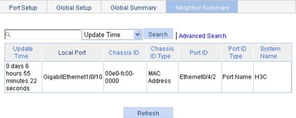
LLDP basic settings configuration example
Network requirements
As shown in Figure 65, a network management station is connected to Switch A over Ethernet and Switch A is connected to a MED device and Switch B through ports GigabitEthernet 1/0/1 and GigabitEthernet 1/0/2 respectively.
Configure LLDP on Switch A and Switch B so that the network management station can determine the link status of Switch A.
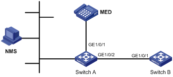
Configuring Switch A
1. Enable LLDP on GigabitEthernet 1/0/1 and GigabitEthernet 1/0/2. (Optional. By default, LLDP is enabled on Ethernet ports.)
2. Set the LLDP operating mode to Rx on GigabitEthernet 1/0/1 and GigabitEthernet 1/0/2:
a. Select Network > LLDP from the navigation tree to enter the Port Setup tab, as shown in Figure 66.
b. Select ports GigabitEthernet1/0/1 and GigabitEthernet1/0/2.
c. Click Modify Selected.
The page shown in Figure 67 appears.
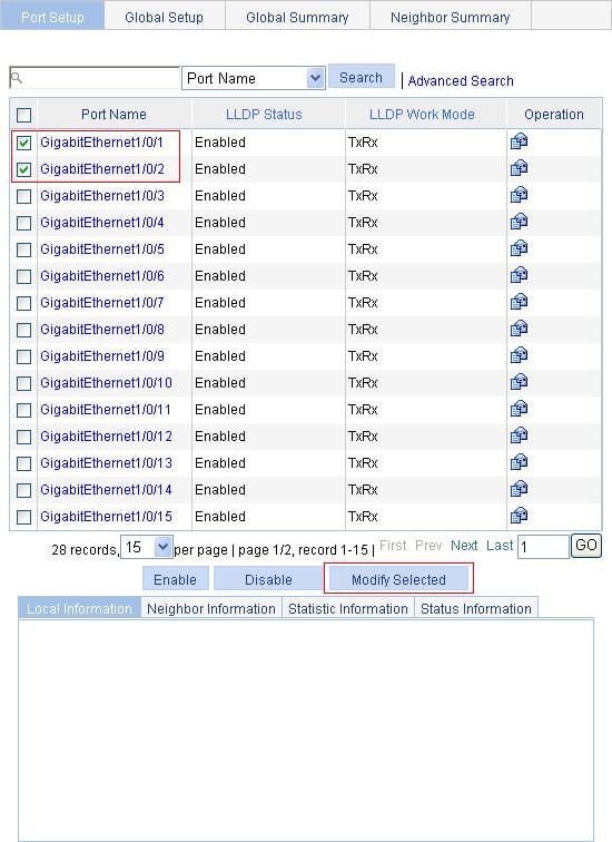
d. Select Rx from the LLDP Operating Mode list.
e. Click Apply.
Figure 67 The page for setting LLDP on multiple ports
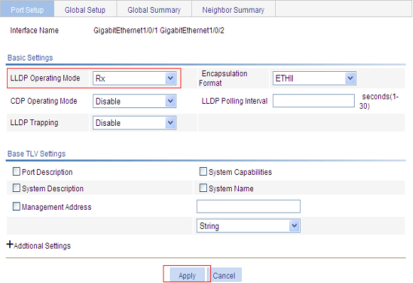
3. Enable global LLDP:
a. Click the Global Setup tab.
b. Select Enable from the LLDP Enable list, as shown in Figure 68.
c. Click Apply.
Figure 68 The Global Setup tab
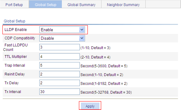
Configuring Switch B
1. Enable LLDP on port GigabitEthernet 1/0/1. (Optional. By default, LLDP is enabled on Ethernet ports.)
2. Set the LLDP operating mode to Tx on GigabitEthernet 1/0/1:
a. Select Network > LLDP from the navigation tree to enter the Port Setup tab.
b. Click the ![]() icon for port
GigabitEthernet1/0/1.
icon for port
GigabitEthernet1/0/1.
c. Select Tx from the LLDP Operating Mode list, as shown in Figure 69.
d. Click Apply.
Figure 69 Set the LLDP operating mode to Tx
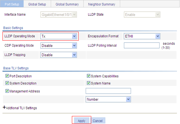
3. Enable global LLDP:
a. Click the Global Setup tab.
b. Select Enable from the LLDP Enable list, as shown in Figure 68
c. Click Apply.
Verifying the configuration
1. Display the status information of port GigabitEthernet1/0/2 on Switch A:
a. Select Network > LLDP from the navigation tree to enter the Port Setup tab.
b. Click the GigabitEthernet1/0/2 port name in the port list.
c. Click the Status Information tab at the lower half of the page.
The output shows that port GigabitEthernet 1/0/2 is connected to a non-MED neighbor device (Switch B), as shown in Figure 70.
Figure 70 The Status Information tab
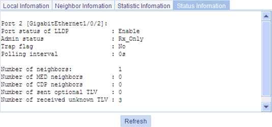
2. Tear down the link between Switch A and Switch B.
3. Click Refresh to display the status information of GigabitEthernet 1/0/2.
The updated status information of port GigabitEthernet 1/0/2 shows that no neighbor device is connected to the port, as shown in Figure 71.
Figure 71 The Status Information tab displaying the updated port status information

CDP-compatible LLDP configuration example
Network requirements
As shown in Figure 72, port GigabitEthernet 1/0/1 and GigabitEthernet 1/0/2 of Switch A are each connected to a Cisco IP phone.
On Switch A configure VLAN 2 as a voice VLAN and configure CDP-compatible LLDP to enable the Cisco IP phones to automatically configure the voice VLAN, confining their voice traffic within the voice VLAN to be separate from other types of traffic.

Configuration procedure
1. Create VLAN 2:
a. Select Network > VLAN from the navigation tree.
b. Click the Create tab.
c. Enter 2 in the VLAN IDs field, as shown in Figure 73.
d. Click Create.
Figure 73 The page for creating VLANs
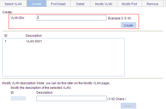
2. Configure GigabitEthernet 1/0/1 and GigabitEthernet 1/0/2 as trunk ports:
a. Select Device > Port Management from the navigation tree.
b. Click the Setup tab.
c. Select Trunk from the Link Type list, and click to select port GE1/0/1 and GE1/0/2 from the chassis front panel, as shown in Figure 74.
d. Click Apply.
Figure 74 The page for configuring ports
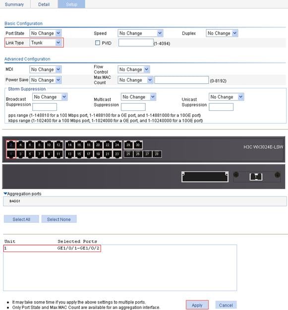
3. Configure the voice VLAN function on the two ports:
a. Select Network > Voice VLAN from the navigation tree.
b. Click the Port Setup tab.
c. To configure the voice VLAN function on the two ports:
¡ Select Auto from the Voice VLAN port mode list.
¡ Select Enable from the Voice VLAN port state list.
¡ Enter the voice VLAN ID 2.
¡ Click to select port GE1/0/1 and GE1/0/2 from the chassis front panel.
d. Click Apply.
Figure 75 The page for configuring the voice VLAN function on ports
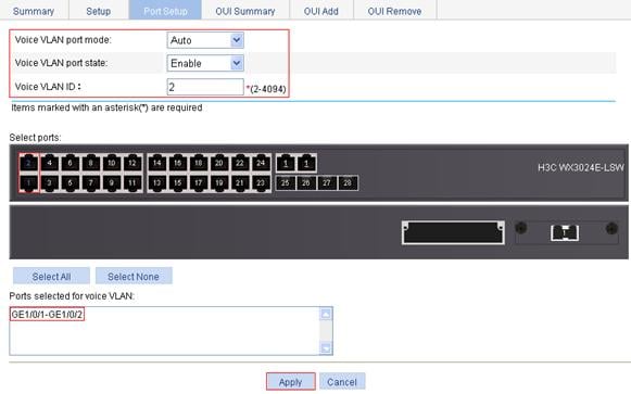
4. Enable LLDP on ports GigabitEthernet 1/0/1 and GigabitEthernet 1/0/2. If LLDP is enabled (the default), skip this step.
5. Set both the LLDP operating mode and the CDP operating mode to TxRx on ports GigabitEthernet 1/0/1 and GigabitEthernet 1/0/2:
a. Select Network > LLDP from the navigation tree to enter the Port Setup tab.
b. Select port GigabitEthernet1/0/1 and GigabitEthernet1/0/2.
c. Click Modify Selected, as shown in Figure 76.
d. Select TxRx from the LLDP Operating Mode list, and select TxRx from the CDP Operating Mode list, as shown in Figure 77.
e. Click Apply.
Figure 77 The page for modifying LLDP settings on ports
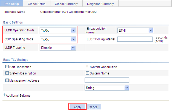
6. Enable global LLDP and CDP compatibility of LLDP:
a. Click the Global Setup tab.
b. Select Enable from the LLDP Enable list, and select Enable from the CDP Compatibility list, as shown in Figure 78.
c. Click Apply.
Figure 78 The Global Setup tab
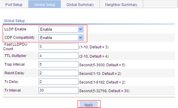
Verifying the configuration
Display information about LLDP neighbors on Switch A after completing the configuration. You can see that Switch A has discovered the Cisco IP phones attached to ports GigabitEthernet1/0/1 and GigabitEthernet1/0/2 and obtained their device information.
Configuration guidelines
When you configure LLDP, follow these guidelines:
· To make LLDP take effect, you must enable it both globally and at port level.
· To advertise LLDP-MED TLVs, you must include the LLDP-MED capabilities set TLV.
· To remove the LLDP-MED capabilities set TLV, you must remove all other LLDP-MED TLVs.
· To remove the MAC/PHY configuration TLV, remove the LLDP-MED capabilities set TLV first.
· If the LLDP-MED capabilities set TLV is included, the MAC/PHY configuration/status TLV is included automatically.
ARP overview
The Address Resolution Protocol (ARP) is used to resolve an IP address into an Ethernet MAC address (or physical address).
In an Ethernet LAN, a device uses ARP to resolve the IP address of the next hop to the corresponding MAC address.
|
|
NOTE: For more information about ARP, see H3C WX3000E Series Wireless Switches Switching Engine Configuration Guide. |
Introduction to gratuitous ARP
Gratuitous ARP packets
In a gratuitous ARP packet, the sender IP address and the target IP address are the IP address of the sending device, the sender MAC address is the MAC address of the sending device, and the target MAC address is the broadcast address ff:ff:ff:ff:ff:ff.
A device sends a gratuitous ARP packet for either of the following purposes:
· Determine whether its IP address is already used by another device. If the IP address is already used, the device will be informed of the conflict by an ARP reply.
· Inform other devices of the change of its MAC address.
Learning of gratuitous ARP packets
With this feature enabled, a device, upon receiving a gratuitous ARP packet, adds an ARP entry that contains the sender IP and MAC addresses in the packet to its ARP table. If the corresponding ARP entry exists, the device updates the ARP entry.
With this feature disabled, the device uses the received gratuitous ARP packets to update existing ARP entries, but not to create new ARP entries.
Displaying ARP entries
Select Network > ARP Management from the navigation tree to enter the default ARP Table page shown in Figure 79. All ARP entries are displayed on the page.
Figure 79 ARP Table configuration page
Creating a static ARP entry
1. Select Network > ARP Management from the navigation tree to enter the default ARP Table page shown in Figure 79.
2. Click Add to enter the New Static ARP Entry page, as shown in Figure 80.
Figure 80 Add a static ARP entry
3. Configure static ARP entry information as described in Table 27.
4. Click Apply.
|
Item |
Description |
|
|
IP Address |
Type an IP address for the static ARP entry. |
|
|
MAC Address |
Type a MAC address for the static ARP entry. |
|
|
Advanced Options |
VLAN ID |
Type a VLAN ID and specify a port for the static ARP entry.
The VLAN ID must be the ID of the VLAN that has already been created, and the port must belong to the VLAN. The corresponding VLAN interface must have been created. |
|
Port |
||
Removing ARP entries
1. Select Network > ARP Management from the navigation tree to enter the default ARP Table page shown in Figure 79.
2. Remove ARP entries:
¡ To remove specific ARP entries, select target ARP entries, and click Del Selected.
¡ To remove all static and dynamic ARP entries, click Delete Static and Dynamic.
¡ To remove all static ARP entries, click Delete Static.
¡ To remove all dynamic ARP entries, click Delete Dynamic.
Configuring gratuitous ARP
1. Select Network > ARP Management from the navigation tree.
2. Click the Gratuitous ARP tab to enter the page shown in Figure 81.
Figure 81 Gratuitous ARP configuration page
3. Configure gratuitous ARP as described in Table 28.
|
Item |
Description |
|
Disable gratuitous ARP packets learning function |
Disable learning of ARP entries according to gratuitous ARP packets. Enabled by default. |
|
Send gratuitous ARP packets when receiving ARP requests from another network segment |
Enable the device to send gratuitous ARP packets upon receiving ARP requests from another network segment. Disabled by default. |
Static ARP configuration example
Network requirements
As shown in Figure 82, hosts are connected to Switch A, which is connected to Router B through interface GigabitEthernet 1/0/1 belonging to VLAN 100. The IP address of Router B is 192.168.1.1/24. The MAC address of Router B is 00e0-fc01-0000.
To enhance communication security between Switch A and Router B, static ARP entries need to be configured on Switch A.
Configuration procedure
1. Create VLAN 100:
a. Select Network > VLAN from the navigation tree.
b. Click the Add tab.
c. Type 100 for VLAN ID, as shown in Figure 83.
d. Click Create.
2. Add GigabitEthernet 1/0/1 to VLAN 100:
a. Click the Modify Port tab.
b. To add GigabitEthernet 1/0/1 to VLAN 100:
¡ Select interface GE1/0/1 in the Select Ports field.
¡ Select the Untagged option in the Select membership type field.
¡ Type 100 for VLAN IDs.
c. Click Apply. A configuration progress dialog box appears.
d. After the configuration succeeds, close the dialog box.
Figure 84 Add GigabitEthernet 1/0/1 to VLAN 100

3. Create VLAN-interface 100:
a. Select Network > VLAN Interface from the navigation tree.
b. Click the Create tab.
c. To create VLAN-interface 100:
¡ Type 100 for VLAN ID.
¡ Select the Configure Primary IPv4 Address box.
¡ Select the Manual option.
¡ Type 192.168.1.2 for IPv4 Address.
¡ Select 24 (255.255.255.0) for Mask Length.
d. Click Apply.
Figure 85 Create VLAN-interface 100
4. Create a static ARP entry:
a. Select Network > ARP Management from the navigation tree to enter the default ARP Table page.
b. Click Add.
c. To create a static ARP entry:
¡ Type 192.168.1.1 for IP Address.
¡ Type 00e0-fc01-0000 for MAC Address.
¡ Select the Advanced Options box.
¡ Type 100 for VLAN ID.
¡ Select GigabitEthernet1/0/1 for Port.
d. Click Apply.
Figure 86 Create a static ARP entry
Overview
Although ARP is easy to implement, it provides no security mechanism and thus is prone to network attacks. Currently, ARP attacks and viruses are threatening LAN security. The device can provide multiple features to detect and prevent such attacks. This chapter mainly introduces these features.
With ARP detection enabled for a specific VLAN, ARP messages arriving on any interface in the VLAN are redirected to the CPU to have their sender MAC and IP addresses checked. ARP messages that pass the check are forwarded; otherwise, they are discarded.
|
|
NOTE: For more information about ARP attack protection configuration, see H3C WX3000E Series Wireless Switches Switching Engine Configuration Guide. |
Configuring ARP detection
|
|
NOTE: If both the ARP detection based on specified objects and the ARP detection based on static IP Source Guard binding entries/DHCP snooping entries/802.1X security entries/OUI MAC addresses are enabled, the former one applies first, and then the latter applies. |
1. Select Network > ARP Anti-Attack from the navigation tree to enter the default ARP Detection page shown in Figure 87.
Figure 87 ARP Detection configuration page
2. Configure ARP detection as described in Table 29.
3. Click Apply.
|
Item |
Description |
|
VLAN Settings |
Select VLANs on which ARP detection is to be enabled. To add VLANs to the Enabled VLANs list box, select one or multiple VLANs from the Disabled VLANs list box and click the << button. To remove VLANs from the Enabled VLANs list box, select one or multiple VLANs from the list box and click the >> button. |
|
Trusted Ports |
Select trusted ports and untrusted ports. To add ports to the Trusted Ports list box, select one or multiple ports from the Untrusted Ports list box and click the << button. To remove ports from the Trusted Ports list box, select one or multiple ports from the list box and click the >> button. |
|
ARP Packet Validity Check |
Select ARP packet validity check modes, including: · Discard the ARP packet whose sender MAC address is different from the source MAC address in the Ethernet header · Discard the ARP packet whose target MAC address is all 0s, all 1s, or inconsistent with the destination MAC address in the Ethernet header · Discard the ARP request whose source IP address is all 0s, all 1s, or a multicast address, and discard the ARP reply whose source and destination IP addresses are all 0s, all 1s, or multicast addresses If none of the above is selected, the system does not check the validity of ARP packets. |
IGMP snooping overview
Internet Group Management Protocol (IGMP) snooping is a multicast constraining mechanism that runs on Layer 2 devices to manage and control multicast groups.
By analyzing received IGMP messages, an IGMP snooping–enabled Layer 2 device establishes mappings between ports and multicast MAC addresses and forwards multicast data based on these mappings.
As shown in Figure 88, when IGMP snooping is not running on the switch, multicast packets are flooded to all devices at Layer 2. When IGMP snooping is running on the switch, multicast packets for known multicast groups are multicast to the receivers, rather than broadcast to all hosts, at Layer 2.
Figure 88 Multicast forwarding before and after IGMP snooping runs
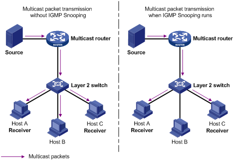
IGMP snooping forwards multicast data to only the receivers that require the data at Layer 2. It has the following advantages:
· Reducing Layer 2 broadcast packets and saving network bandwidth
· Enhancing the security of multicast packets
· Facilitating the implementation of accounting for each host
|
|
NOTE: For more information about IGMP snooping, see H3C WX3000E Series Wireless Switches Switching Engine Configuration Guide. |
Recommended configuration procedure
|
Step |
Remarks |
|
Required Disabled by default. |
|
|
Required Enable IGMP snooping in the VLAN and configure the IGMP snooping version and querier feature. By default, IGMP snooping is disabled in a VLAN.
· IGMP snooping must be enabled globally before it can be enabled in a VLAN. · After enabling IGMP snooping in a VLAN, you cannot enable IGMP or PIM on the corresponding VLAN interface, and vice versa. · When you enable IGMP snooping in a VLAN, this function takes effect for ports in this VLAN only. |
|
|
Optional Configure the maximum number of multicast groups allowed and the fast leave function for ports in the specified VLAN.
· Multicast routing or IGMP snooping must be enabled globally before IGMP snooping can be enabled on a port. · IGMP snooping configured on a port takes effect only after IGMP snooping is enabled in the VLAN or IGMP is enabled on the VLAN interface. |
|
|
Optional |
Enabling IGMP snooping globally
1. Select Network > IGMP snooping in the navigation tree to enter the basic configuration page shown in Figure 89.
2. Select Enable for IGMP Snooping.
3. Click Apply.
Figure 89 Basic IGMP snooping configurations
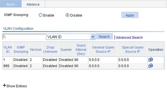
Configuring IGMP snooping in a VLAN
1. Select Network > IGMP snooping in the navigation tree to enter the basic configuration page shown in Figure 89.
2. Click the ![]() icon
corresponding to the VLAN to enter the page you can configure IGMP snooping in
the VLAN, as shown in Figure
90.
icon
corresponding to the VLAN to enter the page you can configure IGMP snooping in
the VLAN, as shown in Figure
90.
Figure 90 VLAN configuration
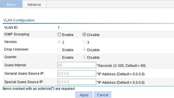
3. Configure the parameters as described in Table 30.
4. Click Apply.
|
Item |
Description |
|
VLAN ID |
This field displays the ID of the VLAN to be configured. |
|
IGMP snooping |
Enable or disable IGMP snooping in the VLAN. You can proceed with the subsequent configurations only if Enable is selected here. |
|
Version |
By configuring an IGMP snooping version, you actually configure the versions of IGMP messages that IGMP snooping can process. · IGMP snooping version 2 can process IGMPv1 and IGMPv2 messages, but not IGMPv3 messages, which will be flooded in the VLAN. · IGMP snooping version 3 can process IGMPv1, IGMPv2, and IGMPv3 messages. |
|
Drop Unknown |
Enable or disable the function of dropping unknown multicast packets. Unknown multicast data refers to multicast data for which no entries exist in the IGMP snooping forwarding table. · With the function of dropping unknown multicast data enabled, the switch drops all the unknown multicast data received. · With the function of dropping unknown multicast data disabled, the switch floods unknown multicast data in the VLAN to which the unknown multicast data belong. |
|
Querier |
Enable or disable the IGMP snooping querier function. On a network without Layer 3 multicast devices, no IGMP querier-related function can be implemented because a Layer 2 device does not support IGMP. To address this issue, you can enable IGMP snooping querier on a Layer 2 device so that the device can generate and maintain multicast forwarding entries at data link layer, thereby implementing IGMP querier-related functions. |
|
Query interval |
Configure the IGMP query interval. |
|
General Query Source IP |
Specify the source IP address of general queries |
|
Special Query Source IP |
Specify the source IP address of group-specific queries |
Configuring IGMP snooping port functions
1. Select Network > IGMP snooping in the navigation tree.
2. Click the Advanced tab to enter the page shown in Figure 91.
Figure 91 Advanced configuration
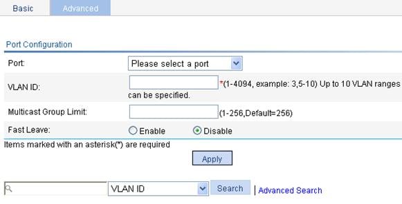
3. Configure the parameters as described in Table 31.
4. Click Apply.
|
Item |
Description |
|
Port |
Select the port on which advanced IGMP snooping features are to be configured. The port can be an Ethernet port or Layer-2 aggregate port. After a port is selected, advanced features configured on this port are displayed at the lower part of this page.
Advanced IGMP snooping features configured on a Layer 2 aggregate port do not interfere with features configured on its member ports, nor do they take part in aggregation calculations; features configured on a member port of the aggregate group will not take effect until it leaves the aggregate group |
|
VLAN ID |
Specify a VLAN in which you can configure the fast leave function for the port or the maximum number of multicast groups allowed on the port. Configurations made in a VLAN take effect for the ports in this VLAN only. |
|
Group Limit |
Configure the maximum number of multicast groups that the port can join. With this feature, you can regulate multicast traffic on the port.
When the number of multicast groups a port has joined reaches the configured threshold, the system deletes all the forwarding entries persistent on that port from the IGMP snooping forwarding table, and the hosts on this port need to join the multicast groups again. |
|
Fast Leave |
Enable or disable the fast leave function for the port. With the fast leave function enabled on a port, the switch, when receiving an IGMP leave message on the port, immediately deletes that port from the outgoing port list of the corresponding forwarding table entry. Then, when receiving IGMP group-specific queries for that multicast group, the switch will not forward them to that port. In VLANs where only one host is attached to each port, the fast leave function helps improve bandwidth and resource usage.
If fast leave is enabled for a port to which more than one host is attached, when one host leaves a multicast group, the other hosts listening to the same multicast group will fail to receive multicast data. |
Display IGMP snooping multicast entry information
1. Select Network > IGMP snooping in the navigation tree to enter the basic configuration page shown in Figure 89.
2. Click the plus sign (+) in front of Show Entries to display information about IGMP snooping multicast entries, as shown in Figure 92.
Figure 92 Display entry information
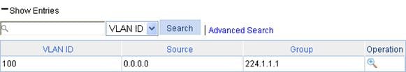
3. Click the ![]() icon corresponding to an entry to view the
detailed information of the
entry, as shown in Figure 93.
icon corresponding to an entry to view the
detailed information of the
entry, as shown in Figure 93.
Figure 93 Information about an IGMP snooping multicast entry
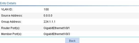
|
Field |
Description |
|
VLAN ID |
ID of the VLAN to which the entry belongs |
|
Source Address |
Multicast source address, where 0.0.0.0 indicates all multicast sources. |
|
Group Address |
Multicast group address |
|
Router Port(s) |
All router ports |
|
Member Port(s) |
All member ports |
IGMP snooping configuration example
Network requirements
· As shown in Figure 94, Router A connects to a multicast source (Source) through Ethernet 1/2, and to Switch A through Ethernet 1/1.
· The multicast source sends multicast data to group 224.1.1.1. Host A is a receiver of the multicast group.
· IGMPv2 runs on Router A and IGMP snooping version 2 runs on Switch A.
· The function of dropping unknown multicast packets is enabled on Switch A to prevent Switch A from flooding multicast packets in the VLAN if no corresponding Layer 2 forwarding entry exists.
· The fast leave function is enabled for GigabitEthernet 1/0/3 on Switch A to improve bandwidth and resource usage.
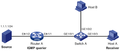
Configuring Router A
Enable IP multicast routing, enable PIM-DM on each interface, and enable IGMP on Ethernet 1/1. (Details not shown)
Configuring Switch A
1. Create VLAN 100:
a. Select Network > VLAN in the navigation tree.
b. Click the Create tab.
c. Enter 100 as the VLAN ID.
d. Click Create.
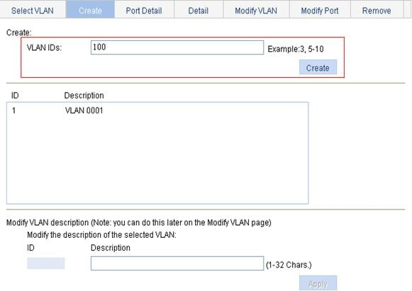
2. Add GigabitEthernet 1/0/1 through GigabitEthernet 1/0/3 to VLAN 100:
a. Click the Modify Port tab.
b. To add GigabitEthernet 1/0/1 through GigabitEthernet 1/0/3 to VLAN 100:
¡ Select GE1/0/1, GE1/0/2, and GE1/0/3 in the Select Ports field.
¡ Select the Untagged option for Select membership type.
¡ Enter 100 as the VLAN ID.
c. Click Apply.
Figure 96 Add a port to the VLAN

3. Enable IGMP snooping globally:
a. Select Network > IGMP snooping from the navigation tree.
b. Select Enable for IGMP Snooping.
c. Click Apply.
Figure 97 Enable IGMP snooping globally
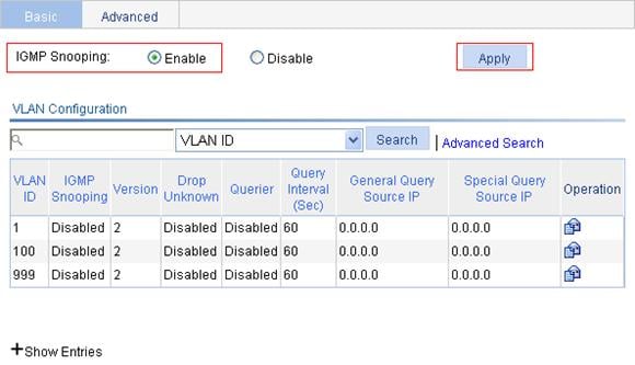
4. In VLAN 100, enable IGMP snooping and the function of dropping unknown multicast data:
a. Click the ![]() icon corresponding to VLAN 100.
icon corresponding to VLAN 100.
b. To enable IGMP snooping and the function of dropping unknown multicast data:
¡ Select the Enable option for IGMP snooping and 2 for Version.
¡ Select the Enable option for Drop Unknown.
¡ Select the Disable option for Querier.
c. Click Apply.
Figure 98 Configure IGMP snooping in the VLAN
5. Enable the fast leave function for GigabitEthernet 1/0/3:
a. Click the Advanced tab.
b. To enable the fast leave function for GigabitEthernet 1/0/3:
¡ Select GigabitEthernet 1/0/3 from the Port list.
¡ Enter 100 as the VLAN ID.
¡ Select the Enable option for Fast Leave.
c. Click Apply.
Figure 99 Configure IGMP snooping on GigabitEthernet 1/0/3
Verifying the configuration
Display IGMP snooping multicast table information on Switch A.
1. Select Network > IGMP snooping in the navigation tree to enter the basic configuration page.
2. Click the plus sign (+) in front of Show Entries in the basic VLAN configuration page to display information about IGMP snooping multicast entries, as shown in Figure 100.
Figure 100 IGMP snooping multicast entry information displaying page
3. Click the ![]() icon corresponding to the multicast entry (0.0.0.0, 224.1.1.1) to
view information about this entry,
as shown in Figure 101.
icon corresponding to the multicast entry (0.0.0.0, 224.1.1.1) to
view information about this entry,
as shown in Figure 101.
Figure 101 Information about an IGMP snooping multicast entry
The output shows that GigabitEthernet 1/0/3 of Switch A is listening to multicast streams destined for multicast group 224.1.1.1.
IPv4 and IPv6 routing configuration
Overview
Upon receiving a packet, a router determines the optimal route based on the destination address and forwards the packet to the next router in the path. When the packet reaches the last router, it then forwards the packet to the destination host. Routing provides the path information that guides the forwarding of packets. Routers are responsible for routing packets on the Internet. A router selects an appropriate route according to the destination address of a received packet and forwards the packet to the next router. The last router on the path is responsible for sending the packet to the destination host.
A router selects optimal routes from the routing table, and sends them to the forwarding information base (FIB) table to guide packet forwarding. Each router maintains a routing table and a FIB table.
Static routes are manually configured. If a network’s topology is simple, you only need to configure static routes for the network to work properly. Static routes cannot adapt to network topology changes. If a fault or a topological change occurs in the network, the network administrator must modify the static routes manually.
|
|
NOTE: For more information about routing table and static route, see H3C WX3000E Series Wireless Switches Switching Engine Configuration Guide. |
Displaying the IPv4 active route table
Select Network > IPv4 Routing from the navigation tree to enter the page shown in Figure 102.
Figure 102 IPv4 active route table
|
Field |
Description |
|
Destination IP Address |
Destination IP address and subnet mask of the IPv4 route |
|
Mask |
|
|
Protocol |
Protocol that discovered the IPv4 route |
|
Preference |
Preference value for the IPv4 route The smaller the number, the higher the preference. |
|
Next Hop |
Next hop IP address of the IPv4 route |
|
Interface |
Outgoing interface of the IPv4 route. Packets destined for the specified network segment will be sent out the interface. |
Creating an IPv4 static route
1. Select Network > IPv4 Routing from the navigation tree.
2. Click the Create tab to enter the IPv4 static route configuration page, as shown in Figure 103.
Figure 103 Create an IPv4 static route
3. Configure IPv4 static route information as described in Table 34.
4. Click Apply.
|
Item |
Description |
|
Destination IP Address |
Type the destination host or network IP address, in dotted decimal notation. |
|
Mask |
Type the mask of the destination IP address. You can type a mask length or a mask in dotted decimal notation. |
|
Preference |
Set a preference value for the static route. The smaller the number, the higher the preference. For example, specifying the same preference for multiple static routes to the same destination enables load sharing on the routes, while specifying different preferences enables route backup. |
|
Next Hop |
Type the next hop IP address, in dotted decimal notation. |
|
Interface |
Select the outgoing interface. You can select any available Layer 3 interface, for example, a virtual interface, of the device. If you select NULL 0, the destination IP address is unreachable. |
Displaying the IPv6 active route table
Select Network > IPv6 Routing from the navigation tree to enter the page shown in Figure 104.
Figure 104 IPv6 active route table
|
Field |
Description |
|
Destination IP Address |
Destination IP address and prefix length of the IPv6 route |
|
Prefix Length |
|
|
Protocol |
Protocol that discovered the IPv6 route |
|
Preference |
Preference value for the IPv6 route The smaller the number, the higher the preference. |
|
Next Hop |
Next hop IP address of the IPv6 route |
|
Interface |
Outgoing interface of the IPv6 route. Packets destined for the specified network segment will be sent out the interface. |
Creating an IPv6 static route
1. Select Network > IPv6 Routing from the navigation tree.
2. Click the Create tab to enter the IPv6 static route configuration page, as shown in Figure 105.
Figure 105 Create an IPv6 static route
3. Configure IPv4 static route information as described in Table 36.
4. Click Apply.
|
Item |
Description |
|
Destination IP Address |
Type the destination host or network IP address, in the X:X::X:X format. The 128-bit destination IPv6 address is a hexadecimal address with eight parts separated by colons (:). Each part is represented by a 4-digit hexadecimal integer. |
|
Prefix Length |
Type the prefix length of the destination IPv6 address. |
|
Preference |
Set a preference value for the static route. The smaller the number, the higher the preference. For example, specifying the same preference for multiple static routes to the same destination enables load sharing on the routes, while specifying different priorities for them enables route backup. |
|
Next Hop |
Type the next hop address, in the same format as the destination IP address. |
|
Interface |
Select the outgoing interface. You can select any available Layer 3 interface, for example, a virtual interface, of the device. If you select NULL 0, the destination IPv6 address is unreachable. |
IPv4 static route configuration example
Network requirements
The IP addresses of devices are shown in Figure 106. IPv4 static routes need to be configured on Switch A, Switch B and Switch C for any two hosts to communicate with each other.
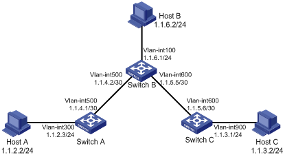
Configuration outlines
1. On Switch A, configure a default route with Switch B as the next hop.
2. On Switch B, configure one static route with Switch A as the next hop and the other with Switch C as the next hop.
3. On Switch C, configure a default route with Switch B as the next hop.
Configuration procedure
1. Configure a default route to Switch B on Switch A:
a. After you log in to the web interface of Switch A, select Network > IPv4 Routing from the navigation tree.
b. Click the Create tab.
c. Type 0.0.0.0 for Destination IP Address, type 0 for Mask, and type 1.1.4.2 for Next Hop, as shown in Figure 107.
d. Click Apply.
Figure 107 Configure a default route

2. Configure a static route to Switch A and Switch C respectively on Switch B:
a. After you log in to the Web interface of Switch B, select Network > IPv4 Routing from the navigation tree.
b. Click the Create tab.
c. To configure a static route to Switch A and Switch C respectively on Switch B:
¡ Type 1.1.2.0 for Destination IP Address.
¡ Type 24 for Mask.
¡ Type 1.1.4.1 for Next Hop.
d. Click Apply.
Figure 108 Configure a static route
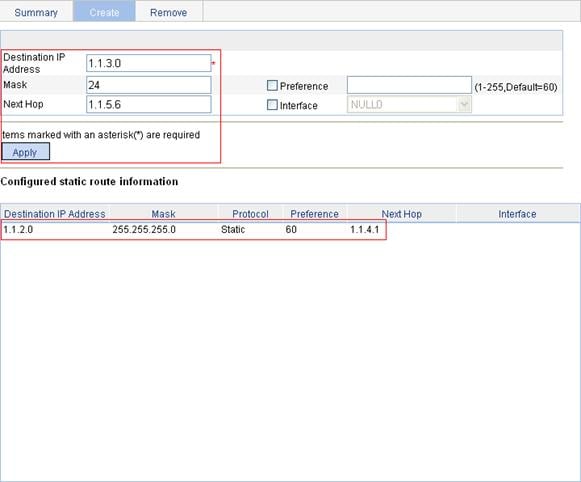
e. Perform the following settings:
¡ Type 1.1.3.0 for Destination IP Address.
¡ Type 24 for Mask.
¡ Type 1.1.5.6 for Next Hop.
f. Click Apply.
3. Configure a default route to Switch B on Switch C:
a. After you log in to the Web interface of Switch C, select Network > IPv4 Routing from the navigation tree.
b. Click the Create tab.
c. To configure a default route to Switch B on Switch C:
¡ Type 0.0.0.0 for Destination IP Address.
¡ Type 0 for Mask.
¡ Type 1.1.5.5 for Next Hop.
d. Click Apply.
Figure 109 Configure a default route
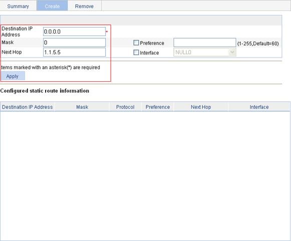
Verifying the configuration
1. Display the route table:
Enter the IPv4 route page of Switch A, Switch B, and Switch C respectively to verify that the newly configured static routes are displayed as active routes on the page.
2. Ping Host B from Host A (assuming both hosts run Windows XP):
C:\Documents and Settings\Administrator>ping 1.1.3.2
Pinging 1.1.3.2 with 32 bytes of data:
Reply from 1.1.3.2: bytes=32 time=1ms TTL=128
Reply from 1.1.3.2: bytes=32 time=1ms TTL=128
Reply from 1.1.3.2: bytes=32 time=1ms TTL=128
Reply from 1.1.3.2: bytes=32 time=1ms TTL=128
Ping statistics for 1.1.3.2:
Packets: Sent = 4, Received = 4, Lost = 0 (0% loss),
Approximate round trip times in milli-seconds:
Minimum = 1ms, Maximum = 1ms, Average = 1ms
IPv6 static route configuration example
Network requirements
The IP addresses of devices are shown in Figure 110. IPv6 static routes need to be configured on Switch A, Switch B and Switch C for any two hosts to communicate with each other.
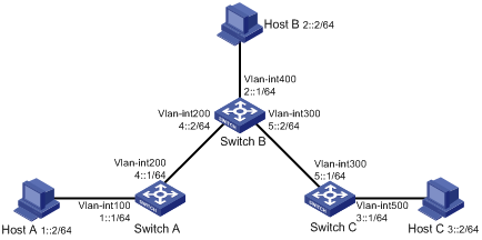
Configuration outlines
1. On Switch A, configure a default route with Switch B as the next hop.
2. On Switch B, configure one static route with Switch A as the next hop and the other with Switch C as the next hop.
3. On Switch C, configure a default route with Switch B as the next hop.
Configuration procedure
1. Configure a default route to Switch B on Switch A:
a. After you log in to the Web interface of Switch A, select Network > IPv6 Routing from the navigation tree.
b. Click the Create tab.
c. To configure a default route to Switch B on Switch A:
¡ Type :: for Destination IP Address.
¡ Select 0 from the Prefix Length list.
¡ Type 4::2 for Next Hop.
d. Click Apply.
Figure 111 Configure a default route
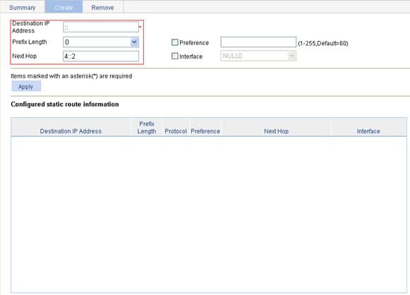
2. Configure a static route to Switch A and Switch C respectively on Switch B:
a. After you log in to the Web interface of Switch B, select Network > IPv6 Routing from the navigation tree.
b. Click the Create tab.
c. To configure a static route to Switch A and Switch C respectively on Switch B:
¡ Type 1:: for Destination IP Address.
¡ Select 64 from the Prefix Length list.
¡ Type 4::1 for Next Hop.
d. Click Apply.
Figure 112 Configure a static route
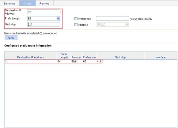
e. Perform the following settings:
¡ Type 3:: for Destination IP Address.
¡ Select 64 from the Prefix Length list.
¡ Type 5::1 for Next Hop.
f. Click Apply.
3. Configure a default route to Switch B on Switch C:
a. After you log in to the Web interface of Switch C, select Network > IPv6 Routing from the navigation tree.
b. Click the Create tab.
c. To configure a default route to Switch B on Switch C:
¡ Type :: for Destination IP Address.
¡ Select 0 from the Prefix Length list.
¡ Type 5::2 for Next Hop.
d. Click Apply.
Figure 113 Configure a default route
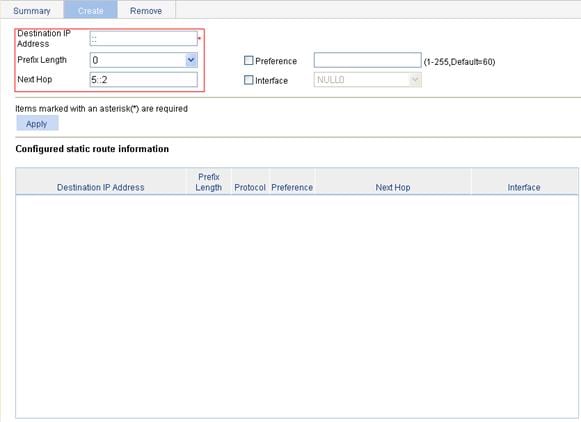
Verifying the configuration
1. Display the route table:
Enter the IPv6 route page of Switch A, Switch B, and Switch C respectively to verify that the newly configured static routes are displayed as active routes on the page.
2. Use the ping command for verification:
Ping Host B from Switch A.
<SwitchA> system-view
[SwitchA] ping ipv6 3::2
PING 3::2 : 56 data bytes, press CTRL_C to break
Reply from 3::2
bytes=56 Sequence=1 hop limit=254 time = 63 ms
Reply from 3::2
bytes=56 Sequence=2 hop limit=254 time = 62 ms
Reply from 3::2
bytes=56 Sequence=3 hop limit=254 time = 62 ms
Reply from 3::2
bytes=56 Sequence=4 hop limit=254 time = 63 ms
Reply from 3::2
bytes=56 Sequence=5 hop limit=254 time = 63 ms
--- 3::2 ping statistics ---
5 packet(s) transmitted
5 packet(s) received
0.00% packet loss
round-trip min/avg/max = 62/62/63 ms
Configuration guidelines
When you configure a static route, follow these guidelines:
· If you do not specify the preference when you configure a static route, the default preference will be used. Reconfiguration of the default preference applies only to newly created static routes. Currently, the Web interface does not support configuration of the default preference.
· When you configure a static route, the static route does not take effect if you specify the next hop address first and then configure it as the IP address of a local interface, such as a VLAN interface.
· When specifying the output interface, note that:
¡ If NULL 0 or a loopback interface is specified as the output interface, there is no need to configure the next hop address.
¡ If a point-to-point interface is specified as the output interface, you don’t need to specify the next hop, and there is no need to change the configuration after the peer address has changed. For example, a PPP interface obtains the peer’s IP address through PPP negotiation, and therefore you only need to specify it as the output interface.
¡ If the output interface is an NBMA or P2MP interface, which supports point-to-multipoint networks, the IP address-to-link layer address mapping must be established. Therefore, you are recommended to specify the next hop IP address when you configure it as the output interface.
¡ If you want to specify a broadcast interface (such as a VLAN interface) as the output interface, which may have multiple next hops, you need to specify the next hop at the same time.
· You can delete only IPv4/IPv6 static routes on the Remove tab.
|
|
NOTE: · After the DHCP client is enabled on an interface, the interface can dynamically obtain an IP address and other configuration parameters from the DHCP server. This facilitates configuration and centralized management. For more information about the DHCP client configuration, see the chapters “VLAN interface configuration” and “Port management.” · For more information about DHCP, see H3C WX3000E Series Wireless Switches Switching Engine Configuration Guide. |
Overview
Introduction to DHCP
The Dynamic Host Configuration Protocol (DHCP) provides a framework to assign configuration information to network devices.
DHCP uses the client-server model. Figure 114 shows a typical DHCP application.
Figure 114 A typical DHCP application

Introduction to DHCP snooping
|
|
NOTE: The DHCP snooping-enabled device must be either between the DHCP client and relay agent, or between the DHCP client and server. It does not work if it is between the DHCP relay agent and DHCP server. |
As a DHCP security feature, DHCP snooping can implement the following:
· Recording IP-to-MAC mappings of DHCP clients
· Ensuring DHCP clients to obtain IP addresses from authorized DHCP servers
Recording IP-to-MAC mappings of DHCP clients
DHCP snooping reads DHCP-REQUEST messages and DHCP-ACK messages from trusted ports to record DHCP snooping entries, including MAC addresses of clients, IP addresses obtained by the clients, ports that connect to DHCP clients, and VLANs to which the ports belong.
Ensuring DHCP clients to obtain IP addresses from authorized DHCP servers
If there is an unauthorized DHCP server on a network, DHCP clients may obtain invalid IP addresses and network configuration parameters, and cannot normally communicate with other network devices. With DHCP snooping, the ports of a device can be configured as trusted or untrusted, ensuring the clients to obtain IP addresses from authorized DHCP servers.
· Trusted: A trusted port forwards DHCP messages normally.
· Untrusted: An untrusted port discards the DHCP-ACK or DHCP-OFFER messages received from any DHCP server.
Configuring the DHCP server
Recommended configuration procedure
|
Step |
Remarks |
|
Required Enable DHCP globally. By default, global DHCP is disabled. |
|
|
Required to configure either of the two
· If the DHCP server and DHCP clients are on the same subnet, make sure the address pool is on the same network segment as the interface with the DHCP server enabled; otherwise, the clients will fail to obtain IP addresses. · If a DHCP client obtains an IP address via a DHCP relay agent, an IP address pool on the same network segment as the DHCP relay agent interface must be configured; otherwise, the client will fail to obtain an IP address. |
|
|
Optional With the DHCP server enabled on an interface, upon receiving a client’s request, the DHCP server will assign an IP address from its address pool to the DHCP client. With DHCP enabled, interfaces work in the DHCP server mode.
· An interface cannot serve as both the DHCP server and the DHCP relay agent. The latest configuration takes effect. · The DHCP server works on interfaces with IP addresses manually configured only. |
Enabling DHCP
1. Select Network > DHCP from the navigation tree to enter the default DHCP Server page shown in Figure 115.
2. Select Enable for DHCP Service to enable DHCP globally.
Figure 115 DHCP configuration page
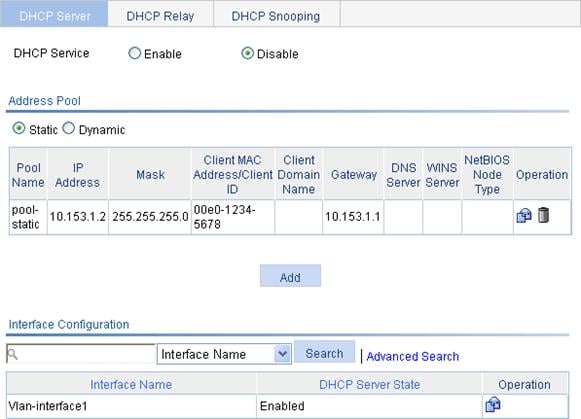
Creating a static address pool for the DHCP server
1. Select Network > DHCP from the navigation tree to enter the default DHCP Server page shown in Figure 115.
2. Select the Static option in the Address Pool field to view all static address pools.
3. Click Add to enter the page shown in Figure 116.
Figure 116 Create a static address pool

4. Configure the static address pool as described in Table 37.
5. Click Apply.
|
Item |
Description |
|
IP Pool Name |
Enter the name of a static address pool. |
|
IP Address |
Enter an IP address and select a subnet mask for the static address pool. The IP address cannot be the IP address of any interface on the DHCP server. Otherwise, an IP address conflict may occur and the bound client cannot obtain an IP address correctly. You can type a mask length or a mask in dotted decimal notation. |
|
Mask |
|
|
Client MAC Address |
Configure the client MAC address or the client ID for the static address pool
The client ID must be identical to the ID of the client to be bound. Otherwise, the client cannot obtain an IP address. |
|
Client ID |
|
|
Client Domain Name |
Enter the domain name suffix for the client. With the suffix assigned, the client only needs to input part of a domain name, and the system will add the domain name suffix for name resolution. |
|
Gateway Address |
Enter the gateway addresses for the client. A DHCP client that wants to access an external host needs to send requests to a gateway. You can specify gateways in each address pool and the DHCP server will assign gateway addresses while assigning an IP address to the client. Up to eight gateways can be specified in a DHCP address pool, separated by commas. |
|
DNS Server Address |
Enter the DNS server addresses for the client. To allow the client to access a host on the Internet through DNS, you need to specify a DNS server address. Up to eight DNS servers can be specified in a DHCP address pool, separated by commas. |
|
WINS Server Address |
Enter the WINS server addresses for the client. If b-node is specified for the client, you do not need to specify any WINS server address. Up to eight WINS servers can be specified in a DHCP address pool, separated by commas. |
|
NetBIOS Node Type |
Select the NetBIOS node type for the client. |
Creating a dynamic address pool for the DHCP server
1. Select Network > DHCP from the navigation tree to enter the default DHCP Server page shown in Figure 115.
2. Select the Dynamic option in the Address Pool field to view all dynamic address pools.
3. Click Add to enter the page shown in Figure 117.
Figure 117 Create a dynamic address pool
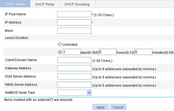
4. Configure the dynamic address pool as described in Table 38.
5. Click Apply.
|
Item |
Description |
|
|
IP Pool Name |
Enter the name of a dynamic address pool. |
|
|
IP Address |
Enter an IP address segment for dynamic allocation. To avoid address conflicts, the DHCP server excludes the IP addresses used by gateways or FTP servers from dynamic allocation. You can type a mask length or a mask in dotted decimal notation. |
|
|
Mask |
||
|
Lease Duration |
Unlimited |
Configure the address lease duration for the address pool. Unlimited indicates the infinite duration. |
|
days/hours/minutes |
||
|
Client Domain Name |
Enter the domain name suffix for the client. With the suffix assigned, the client only needs to input part of a domain name, and the system will add the domain name suffix for name resolution. |
|
|
Gateway Address |
Enter the gateway addresses for the client. DHCP clients that want to access hosts outside the local subnet request gateways to forward data. You can specify gateways in each address pool for clients and the DHCP server will assign gateway addresses while assigning an IP address to the client. Up to eight gateways can be specified in a DHCP address pool, separated by commas. |
|
|
DNS Server Address |
Enter the DNS server addresses for the client. To allow the client to access a host on the Internet via the host name, you need to specify DNS server addresses. Up to eight DNS servers can be specified in a DHCP address pool, separated by commas. |
|
|
WINS Server Address |
Enter the WINS server addresses for the client. If b-node is specified for the client, you do not need to specify any WINS server address. Up to eight WINS servers can be specified in a DHCP address pool, separated by commas. |
|
|
NetBIOS Node Type |
Select the NetBIOS node type for the client. |
|
Enabling the DHCP server on an interface
1. Select Network > DHCP from the navigation tree to enter the default DHCP Server page shown in Figure 115.
2. Click the ![]() icon of a specific
interface to enter the page shown in Figure 118.
icon of a specific
interface to enter the page shown in Figure 118.
3. Select Enable for DHCP Server.
4. Click Apply.
Figure 118 Configure a DHCP server interface
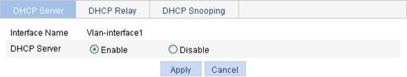
Display the information of assigned IP addresses
1. Select Network > DHCP to enter the default DHCP Server page shown in Figure 115.
2. In the Address In Use area, view the information about the IP address assigned from the address pool.
|
Field |
Description |
|
IP Address |
Assigned IP address |
|
Client MAC Address/Client ID |
Client MAC address or client ID bound to the IP address |
|
Pool Name |
Name of the DHCP address pool where the IP address belongs |
|
Lease Expiration |
Lease time of the IP address |
Configuring the DHCP relay agent
Recommended configuration procedure
|
Step |
Remarks |
|
1. Enabling DHCP and configuring advanced parameters for the DHCP relay agent |
Required Enable DHCP globally and configure advanced DHCP parameters. By default, global DHCP is disabled. |
|
Required To improve reliability, you can specify several DHCP servers as a group on the DHCP relay agent and correlate a relay agent interface with the server group. When the interface receives requesting messages from clients, the relay agent will forward them to all the DHCP servers of the group. |
|
|
Required Enable the DHCP relay agent on an interface, and correlate the interface with a DHCP server group. With DHCP enabled, interfaces work in the DHCP server mode by default.
· An interface cannot serve as both the DHCP server and the DHCP relay agent. The latest configuration takes effect. · If the DHCP relay agent is enabled on an Ethernet subinterface, a packet received from a client on this interface must contain a VLAN tag and the VLAN tag must be the same as the VLAN ID of the subinterface; otherwise, the packet is discarded. · The DHCP relay agent works on interfaces with IP addresses manually configured only. · If an Ethernet subinterface serves as a DHCP relay agent, it conveys IP addresses only to subinterfaces of DHCP clients. In this case, a PC cannot obtain an IP address as a DHCP client. |
|
|
Optional Create a static IP-to-MAC binding, and view static and dynamic bindings. The DHCP relay agent can dynamically record clients’ IP-to-MAC bindings after clients get IP addresses. It also supports static bindings, that is, you can manually configure IP-to-MAC bindings on the DHCP relay agent, so that users can access external network using fixed IP addresses. By default, no static binding is created. |
Enabling DHCP and configuring advanced parameters for the DHCP relay agent
1. Select Network > DHCP from the navigation tree, and click the DHCP Relay tab to enter the DHCP Relay page.
2. Click Display Advanced Configuration to expand the advanced DHCP relay agent configuration field, as shown in Figure 119.
Figure 119 DHCP relay agent configuration page
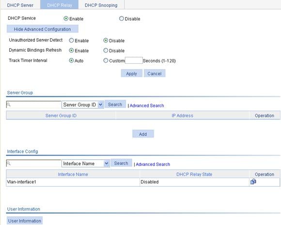
3. Enable DHCP and configure advanced DHCP relay agent parameters as described in Table 40.
4. Click Apply.
|
Item |
Description |
|
DHCP Service |
Enable or disable global DHCP. |
|
Unauthorized Server Detect |
Enable or disable unauthorized DHCP server detection. There are unauthorized DHCP servers on networks, which reply DHCP clients with wrong IP addresses. With this feature enabled, upon receiving a DHCP request, the DHCP relay agent will record the IP address of any DHCP server that assigned an IP address to the DHCP client and the receiving interface. The administrator can use this information to check out DHCP unauthorized servers. The device puts a record once for each DHCP server. The administrator needs to find unauthorized DHCP servers from the log information. After the information of recorded DHCP servers is cleared, the relay agent will re-record server information following this mechanism. |
|
Dynamic Bindings Refresh |
Enable or disable periodic refresh of dynamic client entries, and set the refresh interval. Via the DHCP relay agent, a DHCP client sends a DHCP-RELEASE unicast message to the DHCP server to relinquish its IP address. In this case the DHCP relay agent simply conveys the message to the DHCP server, thus it does not remove the IP address from dynamic client entries. To solve this problem, the periodic refresh of dynamic client entries feature is introduced. With this feature, the DHCP relay agent uses the IP address of a client and the MAC address of the DHCP relay agent interface to periodically send a DHCP-REQUEST message to the DHCP server. · If the server returns a DHCP-ACK message or does not return any message within a specified interval, which means that the IP address is assignable now, the DHCP relay agent will age out the client entry. · If the server returns a DHCP-NAK message, which means the IP address is still in use, the relay agent will not age it out. Note that if the Auto option is clicked on, the refresh interval is calculated by the relay agent according to the number of client entries. |
|
Track Timer Interval |
Creating a DHCP server group
1. Select Network > DHCP from the navigation tree to enter the default DHCP Relay page shown in Figure 119.
2. In the Server Group field, click Add to enter the page shown in Figure 120.
Figure 120 Create a server group
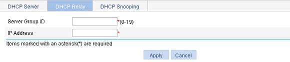
3. Configure DHCP server group information as described in Table 41.
4. Click Apply.
|
Item |
Description |
|
Server Group ID |
Enter the ID of a DHCP server group. You can create up to 20 DHCP server groups. |
|
IP Address |
Enter the IP address of a server in the DHCP server group. The server IP address cannot be on the same subnet as the IP address of the DHCP relay agent; otherwise, the client cannot obtain an IP address. |
Enabling the DHCP relay agent on an interface
1. Select Network > DHCP from the navigation tree to enter the default DHCP Relay page shown in Figure 119.
2. In the Interface Config field, click the ![]() icon of a specific
interface to enter the page shown in Figure 121.
icon of a specific
interface to enter the page shown in Figure 121.
Figure 121 Configure a DHCP relay agent interface
3. Enable DHCP relay agent on the interface as described in Table 42.
4. Click Apply.
|
Item |
Description |
|
Interface Name |
This field displays the name of a specific interface. |
|
DHCP Relay |
Enable or disable the DHCP relay agent on the interface. If the DHCP relay agent is disabled, the DHCP server is enabled on the interface. |
|
Address Match Check |
Enable or disable IP address check. With this function enabled, the DHCP relay agent checks whether a requesting client’s IP and MAC addresses match a binding (dynamic or static) on the DHCP relay agent. If not, the client cannot access outside networks via the DHCP relay agent. This prevents invalid IP address configuration. |
|
Server Group ID |
Correlate the interface with a DHCP server group. A DHCP server group can be correlated with multiple interfaces. |
Configuring and displaying clients' IP-to-MAC bindings
1. Select Network > DHCP from the navigation tree to enter the default DHCP Relay page shown in Figure 119.
2. In the User Information field, click the User Information button to view static and dynamic bindings, as shown in Figure 122.
Figure 122 Display clients' IP-to-MAC bindings
3. Click Add to enter the page shown in Figure 123.
Figure 123 Create a static IP-to-MAC binding
4. Configure the static IP-to-MAC binding as described in Table 43.
5. Click Apply.
|
Item |
Description |
|
IP Address |
Enter the IP address of a DHCP client. |
|
MAC Address |
Enter the MAC address of the DHCP client. |
|
Interface Name |
Select the Layer 3 interface connected with the DHCP client.
The interface of a static binding entry must be configured as a DHCP relay agent; otherwise, address entry conflicts may occur. |
Configuring DHCP snooping
|
|
NOTE: A DHCP snooping enabled device does not work if it is between the DHCP relay agent and DHCP server, and it can work when it is between the DHCP client and relay agent or between the DHCP client and server. |
Recommended configuration procedure
|
Step |
Remarks |
|
Required By default, DHCP snooping is disabled. |
|
|
Required Specify an interface as trusted and configure DHCP snooping to support Option 82. By default, an interface is untrusted and DHCP snooping does not support Option 82.
You need to specify the ports connected to the authorized DHCP servers as trusted to make sure that DHCP clients can obtain valid IP addresses. The trusted port and the port connected to the DHCP client must be in the same VLAN. |
|
|
Optional Display clients' IP-to-MAC bindings recorded by DHCP snooping. |
Enabling DHCP snooping
1. Select Network > DHCP from the navigation tree.
2. Click the DHCP Snooping tab to enter the page shown in Figure 124.
3. Enable DHCP snooping in the DHCP Snooping field.
Figure 124 DHCP snooping configuration page
Configuring DHCP snooping functions on an interface
1. Select Network > DHCP from the navigation tree.
2. Click the DHCP Snooping tab to enter the page shown in Figure 124.
3. In the Interface Config
field, click the ![]() icon of a specific interface to enter the page shown in Figure 125.
icon of a specific interface to enter the page shown in Figure 125.
Figure 125 DHCP snooping interface configuration page
4. Configure DHCP snooping functions as described in Table 44.
5. Click Apply.
|
Item |
Description |
|
Interface Name |
This field displays the name of a specific interface. |
|
Interface State |
Configure the interface as trusted or untrusted. |
|
Option 82 Support |
Configure DHCP snooping to support Option 82 or not. |
|
Option 82 Strategy |
Select the handling strategy for DHCP requests containing Option 82. The strategies include: · Drop: The message is discarded if it contains Option 82. · Keep: The message is forwarded without its Option 82 being changed. · Replace: The message is forwarded after its original Option 82 is replaced with the Option 82 padded in normal format. |
Displaying clients' IP-to-MAC bindings
1. Select Network > DHCP from the navigation tree.
2. Click the DHCP Snooping tab to enter the page shown in Figure 124.
3. Click the User Information button to view clients' IP-to-MAC bindings recorded by DHCP snooping, as shown in Figure 126.
Figure 126 DHCP snooping user information
Table 45 Field description
|
Field |
Description |
|
IP Address |
This field displays the IP address assigned by the DHCP server to the client. |
|
MAC Address |
This field displays the MAC address of the client. |
|
Type |
This field displays the client type, which can be: · Dynamic: The IP-to-MAC binding is generated dynamically. · Static: The IP-to-MAC binding is configured manually. Currently, static bindings are not supported. |
|
Interface Name |
This field displays the device interface to which the client is connected. |
|
VLAN |
This field displays the VLAN to which the device belongs. |
|
Remaining Lease Time |
This field displays the remaining lease time of the IP address. |
DHCP server configuration examples
DHCP networking involves two types:
· The DHCP server and clients are on the same subnet.
· The DHCP server and clients are not on the same subnet and communicate with each other through a DHCP relay agent.
The DHCP server configuration for the two types is the same.
Static IP address assignment configuration example
Network requirements
As shown in Figure 127, configure Switch A (DHCP server) to assign Switch B (DHCP client) a static IP address, DNS server address, and gateway address.
Configuration procedure
1. Enable DHCP:
a. Select Network > DHCP > DHCP Server from the navigation tree to enter the DHCP Server page as shown in Figure 128.
b. Select Enable for DHCP Service.
2. Configure a static address pool:
a. Click Add in the Address Pool field. (The Static option is selected by default.)
b. To configure a static address pool:
¡ Enter static-pool for IP Pool Name.
¡ Enter 10.1.1.5 for IP Address.
¡ Enter 255.255.255.128 for Mask.
¡ Enter 000f-e200-0002 for Client MAC Address.
¡ Enter 10.1.1.126 for Gateway Address.
¡ Enter 10.1.1.2 for DNS Server Address.
c. Click Apply.
Figure 129 Configure a static address pool
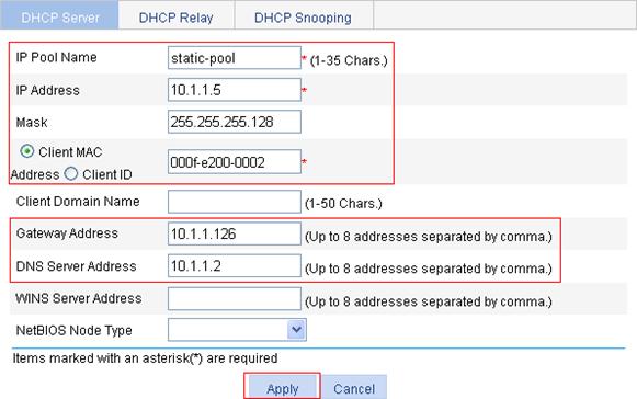
3. Enable the DHCP server on VLAN-interface 9: (This operation can be omitted because the DHCP server is enabled on the interface by default.)
a. Click the ![]() icon of VLAN-interface 9 in the Interface Configuration field.
icon of VLAN-interface 9 in the Interface Configuration field.
b. Select Enable for DHCP Server, as shown in Figure 130.
c. Click Apply.
Figure 130 Enable the DHCP server on an interface
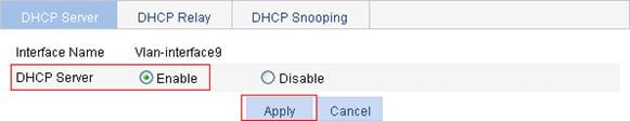
Dynamic IP address assignment configuration example
Network requirements
· As shown in Figure 131, the DHCP server (Switch A) assigns IP addresses to clients on subnet 10.1.1.0/24, which is subnetted into 10.1.1.0/25 and 10.1.1.128/25.
· The IP addresses of VLAN-interface 1 and VLAN-interface 9 on Switch A are 10.1.1.1/25 and 10.1.1.129/25 respectively.
· In subnet 10.1.1.0/25, configure the address lease duration as ten days and twelve hours, domain name suffix aabbcc.com, DNS server address 10.1.1.2/25, WINS server address 10.1.1.4/25, and gateway address 10.1.1.126/25.
· In the subnet 10.1.1.128/25, configure the address lease duration as five days, domain name suffix aabbcc.com, DNS server address 10.1.1.2/25, and gateway address 10.1.1.254/25.
· The domain name suffix and DNS server address on subnets 10.1.1.0/25 and 10.1.1.128/25 are the same. Therefore, the domain name suffix and DNS server address need to be configured only for subnet 10.1.1.0/24. Subnet 10.1.1.0/25 and 10.1.1.128/25 can inherit the configuration of subnet 10.1.1.0/24.
|
|
NOTE: It is recommended that up to 122 clients can obtain IP addresses from VLAN-interface 1 and up to 124 clients can obtain IP addresses from VLAN-interface 9. |
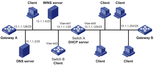
Configuration procedure
1. Enable DHCP:
a. Select Network > DHCP > DHCP Server from the navigation tree to enter the DHCP Server page as shown in Figure 132.
b. Select Enable for DHCP Service.

2. Configure the common attributes (address pool range, client domain name suffix, DNS server address) for the address pool pool0:
a. Select the Dynamic option in the Address Pool field.
b. Click Add.
c. To configure the common attributes for the address pool pool0:
¡ Enter pool0 for IP Pool Name.
¡ Enter 10.1.1.0 for IP Address.
¡ Enter 255.255.255.0 for Mask.
¡ Enter aabbcc.com for Client Domain Name.
¡ Enter 10.1.1.2 for DNS Server Address.
d. Click Apply.
Figure 133 Configure common attributes for pool0
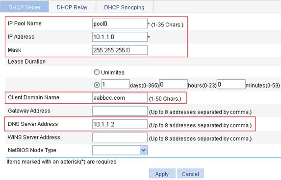
3. Configure the attributes (address pool range, gateway address, address lease duration, and WINS server address) for the DHCP address pool pool1:
a. Click Add.
b. To configure the attributes for the DHCP address pool pool1:
¡ Enter pool1 for IP Pool Name.
¡ Enter 10.1.1.0 for IP Address.
¡ Enter 255.255.255.128 for Mask.
¡ Enter 10 days 12 hours 0 minutes 0 seconds for Lease Duration.
¡ Enter 10.1.1.126 for Gateway Address.
¡ Enter 10.1.1.4 for WINS Server Address.
c. Click Apply.
Figure 134 Configure attributes for pool1
4. Configure the attributes (address pool range, address lease duration, and gateway address) for the DHCP address pool pool2:
a. Click Add.
b. Configure the attributes for the DHCP address pool pool2:
¡ Enter pool2 for IP Pool Name.
¡ Enter 10.1.1.128 for IP Address.
¡ Enter 255.255.255.128 for Mask.
¡ Enter 5 days 0 hours 0 minutes 0 seconds for Lease Duration.
¡ Enter 10.1.1.254 for Gateway Address.
c. Click Apply.
Figure 135 Configure attributes for pool2
DHCP relay agent configuration example
Network requirements
As shown in Figure 136, VLAN-interface 1 on the DHCP relay agent (Switch A) connects to the network where DHCP clients reside. The IP address of VLAN-interface 1 is 10.10.1.1/24 and the IP address of VLAN-interface 2 is 10.1.1.1/24. VLAN-interface 2 is connected to the DHCP server whose IP address is 10.1.1.1/24.
The switch forwards messages between DHCP clients and the DHCP server.
Configuration procedure
1. Enable DHCP:
a. Select Network > DHCP from the navigation tree to enter the default DHCP Relay page.
b. Select Enable for DHCP Service, as shown in Figure 137.
c. Click Apply.

2. Configure a DHCP server group:
a. In the Server Group field, click Add.
b. Enter 1 for Server Group ID, and enter 10.1.1.1 for IP Address, as shown in Figure 138.
c. Click Apply.
Figure 138 Add a DHCP server group
3. Enable the DHCP relay agent on VLAN-interface 1:
a. In the Interface Config field, click the ![]() icon of VLAN-interface 1.
icon of VLAN-interface 1.
b. Select the Enable option for DHCP Relay, and select 1 for Server Group ID, as shown in Figure 139.
c. Click Apply.
Figure 139 Enable the DHCP relay agent on an interface and correlate it with a server group
|
|
NOTE: Because the DHCP relay agent and server are on different subnets, you need to configure a static route or dynamic routing protocol to make them reachable to each other. |
DHCP snooping configuration example
Network requirements
As shown in Figure 140, a DHCP snooping device (Switch B) is connected to a DHCP server through GigabitEthernet 1/0/1, and to DHCP clients through GigabitEthernet 1/0/2 and GigabitEthernet 1/0/3.
· Enable DHCP snooping on Switch B and configure DHCP snooping to support Option 82. Configure the handling strategy for DHCP requests containing Option 82 as replace.
· Enable GigabitEthernet 1/0/1 to forward DHCP server responses; disable GigabitEthernet 1/0/2 and GigabitEthernet 1/0/3 from forwarding DHCP server responses.
· Configure Switch B to record clients’ IP-to-MAC address bindings in DHCP-REQUEST messages and DHCP-ACK messages received from a trusted port.
Configuration procedure
1. Enable DHCP snooping:
a. Select Network > DHCP from the navigation tree.
b. Click the DHCP Snooping tab.
c. Select Enable for DHCP Snooping, as shown in Figure 141.
Figure 141 Enable DHCP snooping
2. Configure DHCP snooping functions on GigabitEthernet 1/0/1:
a. Click the ![]() icon of GigabitEthernet 1/0/1 on the interface list.
icon of GigabitEthernet 1/0/1 on the interface list.
b. Select Trust for Interface State, as shown in Figure 142.
c. Click Apply.
Figure 142 Configure DHCP snooping functions on GigabitEthernet 1/0/1
3. Configure DHCP snooping functions on GigabitEthernet 1/0/2:
a. Click the ![]() icon of GigabitEthernet 1/0/2 on the interface list.
icon of GigabitEthernet 1/0/2 on the interface list.
b. To configure DHCP snooping functions on GigabitEthernet 1/0/2:
¡ Select Untrust for Interface State.
¡ Select Enable for Option 82 Support.
¡ Select Replace for Option 82 Strategy.
c. Click Apply.
Figure 143 Configure DHCP snooping functions on GigabitEthernet 1/0/2
4. Configure DHCP snooping functions on GigabitEthernet 1/0/3:
a. Click the ![]() icon of GigabitEthernet 1/0/3 on the interface list.
icon of GigabitEthernet 1/0/3 on the interface list.
b. To configure DHCP snooping functions on GigabitEthernet 1/0/3:
¡ Select Untrust for Interface State.
¡ Select Enable for Option 82 Support.
¡ Select Replace for Option 82 Strategy.
c. Click Apply.
Figure 144 Configure DHCP snooping functions on GigabitEthernet 1/0/3
Overview
The service management module provides six types of services: FTP, Telnet, SSH, SFTP, HTTP and HTTPS. You can enable or disable the services as needed. In this way, the performance and security of the system can be enhanced, thus secure management of the device can be achieved.
The service management module also provides the function to modify HTTP and HTTPS port numbers, and the function to associate the FTP, HTTP, or HTTPS service with an ACL, thus reducing attacks of illegal users on these services.
FTP service
The File Transfer Protocol (FTP) is an application layer protocol for sharing files between server and client over a TCP/IP network.
Telnet service
The Telnet protocol is an application layer protocol that provides remote login and virtual terminal functions on the network.
SSH service
Secure Shell (SSH) offers an approach to securely logging in to a remote device. By encryption and strong authentication, it protects devices against attacks such as IP spoofing and plain text password interception.
SFTP service
The secure file transfer protocol (SFTP) is a new feature in SSH2.0. SFTP uses the SSH connection to provide secure data transfer. The device can serve as the SFTP server, allowing a remote user to log in to the SFTP server for secure file management and transfer. The device can also serve as an SFTP client, enabling a user to login from the device to a remote device for secure file transfer.
HTTP service
The Hypertext Transfer Protocol (HTTP) is used for transferring web page information across the Internet. It is an application-layer protocol in the TCP/IP protocol suite.
You can log in to the device using the HTTP protocol with HTTP service enabled, accessing and controlling the device with Web-based network management.
HTTPS service
The Secure HTTP (HTTPS) refers to the HTTP protocol that supports the Security Socket Layer (SSL) protocol.
The SSL protocol of HTTPS enhances the security of the device in the following ways:
· Uses the SSL protocol to ensure the legal clients to access the device securely and prohibit the illegal clients;
· Encrypts the data exchanged between the HTTPS client and the device to ensure the data security and integrity, thus realizing the security management of the device;
· Defines certificate attribute-based access control policy for the device to control the access right of the client, in order to further avoid attacks from illegal clients.
Configuring service management
1. Select Network > Service from the navigation tree.
The service management configuration page appears.
2. Configure the service states as described in Table 46.
3. Click Apply.
|
Item |
Description |
|
|
FTP |
Enable FTP service |
Specifies whether to enable the FTP service. The FTP service is disabled by default. |
|
ACL |
Associates the FTP service with an ACL. Only the clients that pass the ACL filtering are permitted to use the FTP service. You can view this configuration item by clicking the expanding button in front of FTP. |
|
|
Telnet |
Enable Telnet service |
Specifies whether to enable the Telnet service. The Telnet service is disabled by default. |
|
SSH |
Enable SSH service |
Specifies whether to enable the SSH service. The SSH service is disabled by default. |
|
SFTP |
Enable SFTP service |
Specifies whether to enable the SFTP service. The SFTP service is disabled by default.
When you enable the SFTP service, the SSH service must be enabled. |
|
HTTP |
Enable HTTP service |
Specifies whether to enable the HTTP service. The HTTP service is enabled by default. |
|
Port Number |
Sets the port number for HTTP service. You can view this configuration item by clicking the expanding button in front of HTTP.
When you modify a port, make sure that the port is not used by other service. |
|
|
ACL |
Associates the HTTP service with an ACL. Only the clients that pass the ACL filtering are permitted to use the HTTP service. You can view this configuration item by clicking the expanding button in front of HTTP. |
|
|
HTTPS |
Enable HTTPS service |
Specifies whether to enable the HTTPS service. The HTTPS service is disabled by default. |
|
Port Number |
Sets the port number for HTTPS service. You can view this configuration item by clicking the expanding button in front of HTTPS.
When you modify a port, make sure that the port is not used by other service. |
|
|
ACL |
Associates the HTTPS service with an ACL. Only the clients that pass the ACL filtering are permitted to use the HTTPS service. You can view this configuration item by clicking the expanding button in front of HTTPS. |
|
|
PKI domain |
Sets the PKI domain for the HTTPS service. You can configure the available PKI domains by selecting Authentication > PKI from the navigation tree at the left side of the interface. For more information, see the chapter “Certificate management.” |
|
Overview
Ping
You can use the ping function to check whether a device with a specified address is reachable, and to examine network connectivity.
A successful execution of the ping command involves the following steps:
1. The source device sends an ICMP echo request (ECHO-REQUEST) to the destination device.
2. The destination device responds by sending an ICMP echo reply (ECHO-REPLY) to the source device after receiving the ICMP echo request.
3. The source device displays related statistics after receiving the reply.
Output of the ping command falls into the following:
· You can ping the IP address or the host name of the destination device. If the target host name cannot be identified, the source device outputs related information.
· If the source device does not receive an ICMP echo reply within the timeout time, it displays the prompt information and the statistics during the ping operation. If the source device receives an ICMP echo reply within the timeout time, it displays the number of bytes of the echo reply, the message sequence number, Time to Live (TTL), the response time, and the statistics during the ping operation.
Statistics during the ping operation include number of packets sent, number of echo reply messages received, percentage of messages not received, and the minimum, average, and maximum response time.
Trace route
By using the trace route command, you can display the Layer 3 devices involved in delivering a packet from source to destination. This function is useful for identification of failed node(s) in the event of network failure.
You can trace route the IP address or the host name of the destination device. If the target host name cannot be identified, the source device outputs related information.
The trace route command involves the following steps in its execution:
1. The source device sends a packet with a TTL value of 1 to the destination device.
2. The first hop (the Layer 3 device that first receives the packet) responds by sending a TTL-expired ICMP message to the source, with its IP address encapsulated. In this way, the source device can get the address of the first Layer 3 device.
3. The source device sends a packet with a TTL value of 2 to the destination device.
4. The second hop responds with a TTL-expired ICMP message, which gives the source device the address of the second Layer 3 device.
5. The above process continues until the ultimate destination device is reached. In this way, the source device can trace the addresses of all the Layer 3 devices involved to get to the destination device.
Ping operation
|
|
NOTE: The Web interface does not support the IPv6 ping operations. |
1. Select Network > Diagnostic Tools from the navigation tree.
The ping configuration page appears.
Figure 146 Ping configuration page
2. Type the IP address or the host name of the destination device.
3. Click Start to execute the ping command.
4. View the result in the Summary area.
Figure 147 Ping operation result
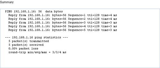
Trace route operation
|
|
NOTE: · The web interface does not support IPv6 trace route operations. · Before performing the trace route operation on the Web interface, on the intermediate device execute the ip ttl-expires enable command to enable the sending of ICMP timeout packets and on the destination device execute the ip unreachables enable command to enable the sending of ICMP destination unreachable packets. |
1. Select Network > Diagnostic Tools from the navigation tree.
2. Select the Trace Route tab.
The trace route configuration page appears.
Figure 148 Trace route configuration page
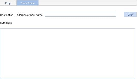
3. Type the IP address or host name of the destination device.
4. Click Start to execute the trace route command.
5. View the output in the Summary area.
Figure 149 Trace route operation result