- Table of Contents
-
- 04-IP Multicast Volume
- 00-IP Multicast Volume Organization
- 01-Mulitcast Overview
- 02-Multicast Routing and Forwarding Configuration
- 03-IGMP Configuration
- 04-PIM Configuration
- 05-MSDP Configuration
- 06-MBGP Configuration
- 07-Multicast VPN Configuration
- 08-IGMP Snooping Configuration
- 09-Multicast VLAN Configuration
- 10-IPv6 Multicast Routing and Forwarding Configuration
- 11-MLD Configuration
- 12-IPv6 PIM Configuration
- 13-IPv6 MBGP Configuration
- 14-MLD Snooping Configuration
- 15-IPv6 Multicast VLAN Configuration
- Related Documents
-
| Title | Size | Download |
|---|---|---|
| 09-Multicast VLAN Configuration | 158.83 KB |
Table of Contents
1 Multicast VLAN Configuration
Introduction to Multicast VLAN
Multicast VLAN Configuration Task List
Configuring Sub-VLAN-Based Multicast VLAN
Configuring Sub-VLAN-Based Multicast VLAN
Configuring Port-Based Multicast VLAN
Configuring User Port Attributes
Configuring Multicast VLAN Ports
Displaying and Maintaining Multicast VLAN
Multicast VLAN Configuration Examples
Sub-VLAN-Based Multicast VLAN Configuration
Port-Based Multicast VLAN Configuration
When configuring multicast VLAN, go to these sections for information you are interested in:
l Introduction to Multicast VLAN
l Multicast VLAN Configuration Task List
l Configuring Sub-VLAN-Based Multicast VLAN
l Configuring Port-Based Multicast VLAN
l Displaying and Maintaining Multicast VLAN
l Multicast VLAN Configuration Examples
Introduction to Multicast VLAN
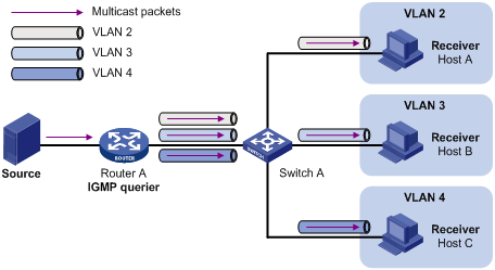
As shown in Figure 1-1, in the traditional multicast programs-on-demand mode, when hosts, Host A, Host B and Host C, belonging to different VLANs require multicast programs on demand service, the Layer 3 device, Router A, needs to forward a separate copy of the multicast traffic in each user VLAN to the Layer 2 device, Switch A. This results in not only waste of network bandwidth but also extra burden on the Layer 3 device.
Figure 1-1 Multicast transmission without multicast VLAN
The multicast VLAN feature configured on the Layer 2 device is the solution to this issue. With the multicast VLAN feature, the Layer 3 device needs to replicate the multicast traffic only in the multicast VLAN instead of making a separate copy of the multicast traffic in each user VLAN. This saves the network bandwidth and lessens the burden of the Layer 3 device.
The multicast VLAN feature can be implemented in two approaches, as described below:
Sub-VLAN-based multicast VLAN
As shown in Figure 1-2, Host A, Host B and Host C are in three different user VLANs. On Switch A, configure VLAN 10 as a multicast VLAN, configure all the user VLANs as sub-VLANs of this multicast VLAN, and enable IGMP Snooping in the multicast VLAN.
Figure 1-2 Sub-VLAN-based multicast VLAN
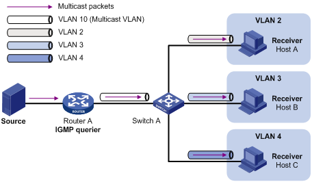
After the configuration, IGMP Snooping manages router ports in the multicast VLAN and member ports in the sub-VLANs. When forwarding multicast data to Switch A, Router A needs to send only one copy of multicast traffic to Switch A in the multicast VLAN, and Switch A distributes the traffic to the multicast VLAN’s sub-VLANs that contain receivers.
Port-based multicast VLAN
As shown in Figure 1-3, Host A, Host B and Host C are in three different user VLANs. All the user ports (ports with attached hosts) on Switch A are hybrid ports. On Switch A, configure VLAN 10 as a multicast VLAN, assign all the user ports to this multicast VLAN, and enable IGMP Snooping in the multicast VLAN and all the user VLANs.
Figure 1-3 Port-based multicast VLAN
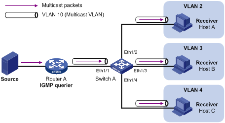
After the configuration, upon receiving an IGMP message on a user port, Switch A tags the message with the multicast VLAN ID and relays it to the IGMP querier, so that IGMP Snooping can uniformly manage the router ports and member ports in the multicast VLAN. When forwarding multicast data to Switch A, Router A needs to send only one copy of multicast traffic to Switch A in the multicast VLAN, and Switch A distributes the traffic to all the member ports in the multicast VLAN.
![]()
l For information about IGMP Snooping, router ports, and member ports, refer to IGMP Snooping Configuration in the IP Multicast Volume.
l For information about VLAN tags, refer to VLAN Configuration in the Access Volume.
Multicast VLAN Configuration Task List
Complete the following tasks to configure multicast VLAN:
|
Task |
Remarks |
|
|
Required Use either approach. |
||
![]()
If you have configured both sub-VLAN-based multicast VLAN and port-based multicast VLAN on a device, the port-based multicast VLAN configuration is given preference.
Configuring Sub-VLAN-Based Multicast VLAN
Configuration Prerequisites
Before configuring sub-VLAN-based multicast VLAN, complete the following tasks:
l Create VLANs as required
l Enable IGMP Snooping in the VLAN to be configured as a multicast VLAN
Configuring Sub-VLAN-Based Multicast VLAN
In this approach, you need to configure a VLAN as a multicast VLAN, and then configure user VLANs as sub-VLANs of the multicast VLAN.
Follow these steps to configure sub-VLAN-based multicast VLAN:
|
To do… |
Use the command… |
Remarks |
|
Enter system view |
system-view |
— |
|
Configure the specified VLAN as a multicast VLAN and enter multicast VLAN view |
multicast-vlan vlan-id |
Required Not a multicast VLAN by default |
|
Configure the specified VLAN(s) as sub-VLAN(s) of the multicast VLAN |
subvlan vlan-list |
Required By default, a multicast VLAN has no sub-VLANs. |
![]()
l You cannot configure multicast VLAN on a device with IP multicast routing enabled.
l The VLAN to be configured as a multicast VLAN must exist.
l The VLANs to be configured as sub-VLANs of the multicast VLAN must exist and must not be sub-VLANs of another multicast VLAN.
l The total number of sub-VLANs of a multicast VLAN must not exceed the maximum number the system can support (an S7500E series Ethernet switch supports up to five multicast VLANs, and supports up to 4000 sub-VLANs for each multicast VLAN. The total number of sub-VLANs for all multicast VLANs on the switch cannot exceed 4000.).
Configuring Port-Based Multicast VLAN
![]()
A user port can be configured as a multicast VLAN port only if it is of the Ethernet or Layer 2 aggregate interface type.
Configuration Prerequisites
Before configuring port-based multicast VLAN, complete the following tasks:
l Create VLANs as required
l Enable IGMP Snooping in the VLAN to be configured as a multicast VLAN
l Enable IGMP Snooping in all the user VLANs
Configuring User Port Attributes
Configure the user ports as hybrid ports that permit packets of the specified user VLAN to pass, and configure the user VLAN to which the user ports belong as the default VLAN.
Configure the user ports to permit packets of the multicast VLAN to pass and untag the packets. Thus, upon receiving multicast packets tagged with the multicast VLAN ID from the upstream device, the Layer 2 device untags the multicast packets and forwards them to its downstream device.
Follow these steps to configure user port attributes:
|
To do... |
Use the command... |
Remarks |
|
Enter system view |
system-view |
— |
|
Enter interface view or port group view |
interface interface-type interface-number |
Required Use either command |
|
port-group { manual port-group-name | aggregation agg-id } |
||
|
Configure the user port link type as hybrid |
port link-type hybrid |
Required Access by default |
|
Specify the user VLAN that comprises the current user port(s) as the default VLAN |
port hybrid pvid vlan vlan-id |
Required VLAN 1 by default |
|
Configure the current user port(s) to permit packets of the specified multicast VLAN(s) to pass and untag the packets |
port hybrid vlan vlan-id-list untagged |
Required By default, a hybrid port permits only packets of VLAN 1 to pass. |
![]()
For details about the port link-type, port hybrid pvid vlan, and port hybrid vlan commands, refer to VLAN Commands in the Access Volume.
Configuring Multicast VLAN Ports
Follow these steps to configure multicast VLAN ports:
|
To do... |
Use the command... |
Remarks |
|
Enter system view |
system-view |
— |
|
Configure the specified VLAN as a multicast VLAN and enter multicast VLAN view |
multicast-vlan vlan-id |
Required Not a multicast VLAN by default |
|
Assign ports to the multicast VLAN |
port interface-list |
Required By default, a multicast VLAN has no ports. |
![]()
l You cannot configure multicast VLAN on a device with multicast routing enabled.
l The VLAN to be configured as a multicast VLAN must exist.
l A port can belong to only one multicast VLAN.
Displaying and Maintaining Multicast VLAN
|
To do… |
Use the command… |
Remarks |
|
Display information about a multicast VLAN |
display multicast-vlan [ vlan-id ] |
Available in any view |
Multicast VLAN Configuration Examples
Sub-VLAN-Based Multicast VLAN Configuration
Network requirements
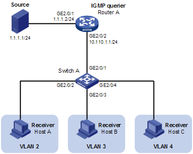
l Router A connects to a multicast source through GigabitEthernet 1/0/1 and to Switch A, through GigabitEthernet 1/0/2.
l IGMPv2 is required on Router A, and IGMPv2 Snooping is required on Switch A. Router A is the IGMP querier.
l Switch A’s GigabitEthernet 2/0/1 belongs to VLAN 10, GigabitEthernet 2/0/2 through GigabitEthernet 2/0/4 belong to VLAN 2 through VLAN 4 respectively, and Host A through Host C are attached to GigabitEthernet 2/0/2 through GigabitEthernet 2/0/4 of Switch A respectively.
l The multicast source sends multicast data to multicast group 224.1.1.1. Host A, Host B, and Host C are receivers of the multicast group.
l Configure the sub-VLAN-based multicast VLAN feature so that Router A just sends multicast data to Switch A through the multicast VLAN and Switch A forwards the traffic to the receivers that belong to different user VLANs.
Network diagram
Figure 1-4 Network diagram for sub-VLAN-based multicast VLAN configuration
Configuration procedure
1) Configure IP addresses
Configure an IP address and subnet mask for each interface as per Figure 1-4. The detailed configuration steps are omitted here.
2) Configure Router A
# Enable IP multicast routing, enable PIM-DM on each interface and enable IGMP on the host-side interface GigabitEthernet 2/0/2.
<RouterA> system-view
[RouterA] multicast routing-enable
[RouterA] interface gigabitethernet 2/0/1
[RouterA-GigabitEthernet2/0/1] pim dm
[RouterA-GigabitEthernet2/0/1] quit
[RouterA] interface gigabitethernet 2/0/2
[RouterA-GigabitEthernet2/0/2] pim dm
[RouterA-GigabitEthernet2/0/2] igmp enable
3) Configure Switch A
# Enable IGMP Snooping globally.
<SwitchA> system-view
[SwitchA] igmp-snooping
[SwitchA-igmp-snooping] quit
# Create VLAN 2 and assign GigabitEthernet 2/0/2 to this VLAN.
[SwitchA] vlan 2
[SwitchA-vlan2] port gigabitethernet 2/0/2
[SwitchA-vlan2] quit
The configuration for VLAN 3 and VLAN 4 is similar to the configuration for VLAN 2.
# Create VLAN 10, assign GigabitEthernet 2/0/1 to this VLAN and enable IGMP Snooping in the VLAN.
[SwitchA] vlan 10
[SwitchA-vlan10] port gigabitethernet 2/0/1
[SwitchA-vlan10] igmp-snooping enable
[SwitchA-vlan10] quit
# Configure VLAN 10 as a multicast VLAN and configure VLAN 2 through VLAN 4 as its sub-VLANs.
[SwitchA] multicast-vlan 10
[SwitchA-mvlan-10] subvlan 2 to 4
[SwitchA-mvlan-10] quit
4) Verify the configuration
# Display information about the multicast VLAN.
[SwitchA] display multicast-vlan
Total 1 multicast-vlan(s)
Multicast vlan 10
subvlan list:
vlan 2-4
port list:
no port
# View the IGMP Snooping multicast group information on Switch A.
[SwitchA] display igmp-snooping group
Total 4 IP Group(s).
Total 4 IP Source(s).
Total 4 MAC Group(s).
Port flags: D-Dynamic port, S-Static port, C-Copy port
Subvlan flags: R-Real VLAN, C-Copy VLAN
Vlan(id):2.
Total 1 IP Group(s).
Total 1 IP Source(s).
Total 1 MAC Group(s).
Router port(s):total 0 port.
IP group(s):the following ip group(s) match to one mac group.
IP group address:224.1.1.1
(0.0.0.0, 224.1.1.1):
Host port(s):total 1 port.
GE2/0/2 (D)
MAC group(s):
MAC group address:0100-5e01-0101
Host port(s):total 1 port.
GE2/0/2
Vlan(id):3.
Total 1 IP Group(s).
Total 1 IP Source(s).
Total 1 MAC Group(s).
Router port(s):total 0 port.
IP group(s):the following ip group(s) match to one mac group.
IP group address:224.1.1.1
(0.0.0.0, 224.1.1.1):
Host port(s):total 1 port.
GE2/0/3 (D)
MAC group(s):
MAC group address:0100-5e01-0101
Host port(s):total 1 port.
GE2/0/3
Vlan(id):4.
Total 1 IP Group(s).
Total 1 IP Source(s).
Total 1 MAC Group(s).
Router port(s):total 0 port.
IP group(s):the following ip group(s) match to one mac group.
IP group address:224.1.1.1
(0.0.0.0, 224.1.1.1):
Host port(s):total 1 port.
GE2/0/4 (D)
MAC group(s):
MAC group address:0100-5e01-0101
Host port(s):total 1 port.
GE2/0/4
Vlan(id):10.
Total 1 IP Group(s).
Total 1 IP Source(s).
Total 1 MAC Group(s).
Router port(s):total 1 port.
GE2/0/1 (D)
IP group(s):the following ip group(s) match to one mac group.
IP group address:224.1.1.1
(0.0.0.0, 224.1.1.1):
Host port(s):total 0 port.
MAC group(s):
MAC group address:0100-5e01-0101
Host port(s):total 0 port.
Port-Based Multicast VLAN Configuration
Network requirements
l As shown in Figure 1-5, Router A connects to a multicast source (Source) through GigabitEthernet 2/0/1, and to Switch A through GigabitEthernet 2/0/2.
l IGMPv2 is required on Router A. IGMPv2 Snooping is required on Switch A. Router A acts as the IGMP querier.
l Switch A’s GigabitEthernet 2/0/1 belongs to VLAN 10, GigabitEthernet 2/0/2 through GigabitEthernet 2/0/4 belong to VLAN 2 through VLAN 4 respectively, and Host A through Host C are attached to GigabitEthernet 2/0/2 through GigabitEthernet 2/0/4 of Switch A respectively.
l The multicast source sends multicast data to multicast group 224.1.1.1. Host A, Host B, and Host C are receivers of the multicast group.
l Configure the port-based multicast VLAN feature so that Router A just sends multicast data to Switch A through the multicast VLAN and Switch A forwards the multicast data to the receivers that belong to different user VLANs.
Network diagram
Figure 1-5 Network diagram for port-based multicast VLAN configuration
Configuration procedure
1) Configure IP addresses
Configure the IP address and subnet mask for each interface as per Figure 1-5. The detailed configuration steps are omitted here.
2) Configure Router A
# Enable IP multicast routing, enable PIM-DM on each interface, and enable IGMP on the host-side interface GigabitEthernet 2/0/2.
<RouterA> system-view
[RouterA] multicast routing-enable
[RouterA] interface gigabitethernet 2/0/1
[RouterA-GigabitEthernet2/0/1] pim dm
[RouterA-GigabitEthernet2/0/1] quit
[RouterA] interface gigabitethernet 2/0/2
[RouterA-GigabitEthernet2/0/2] pim dm
[RouterA-GigabitEthernet2/0/2] igmp enable
3) Configure Switch A
# Enable IGMP Snooping globally.
<SwitchA> system-view
[SwitchA] igmp-snooping
[SwitchA-igmp-snooping] quit
# Create VLAN 10, assign GigabitEthernet 2/0/1 to VLAN 10, and enable IGMP Snooping in this VLAN.
[SwitchA] vlan 10
[SwitchA-vlan10] port gigabitethernet 2/0/1
[SwitchA-vlan10] igmp-snooping enable
[SwitchA-vlan10] quit
# Create VLAN 2 and enable IGMP Snooping in the VLAN.
[SwitchA] vlan 2
[SwitchA-vlan2] igmp-snooping enable
[SwitchA-vlan2] quit
The configuration for VLAN 3 and VLAN 4 is similar. The detailed configuration steps are omitted.
# Configure GigabitEthernet 2/0/2 as a hybrid port. Configure VLAN 2 as the default VLAN. Configure GigabitEthernet 2/0/2 to permit packets of VLAN 2 and VLAN 10 to pass and untag the packets when forwarding them.
[SwitchA] interface gigabitethernet 2/0/2
[SwitchA-GigabitEthernet2/0/2] port link-type hybrid
[SwitchA-GigabitEthernet2/0/2] port hybrid pvid vlan 2
[SwitchA-GigabitEthernet2/0/2] port hybrid vlan 2 untagged
[SwitchA-GigabitEthernet2/0/2] port hybrid vlan 10 untagged
[SwitchA-GigabitEthernet2/0/2] quit
The configuration for GigabitEthernet 2/0/3 and GigabitEthernet 2/0/4 is similar. The detailed configuration steps are omitted.
# Configure VLAN 10 as a multicast VLAN.
[SwitchA] multicast-vlan 10
# Assign GigabitEthernet 2/0/2 and GigabitEthernet 2/0/4 to VLAN 10.
[SwitchA-mvlan-10] port gigabitethernet 2/0/2 to gigabitethernet 2/0/4
[SwitchA-mvlan-10] quit
4) Verify the configuration
# View the multicast VLAN information on Switch A.
[SwitchA] display multicast-vlan
Total 1 multicast-vlan(s)
Multicast vlan 10
subvlan list:
no subvlan
port list:
GE2/0/2 GE2/0/3 GE2/0/4
# View the IGMP Snooping multicast group information on Switch A.
[SwitchA] display igmp-snooping group
Total 1 IP Group(s).
Total 1 IP Source(s).
Total 1 MAC Group(s).
Port flags: D-Dynamic port, S-Static port, C-Copy port
Subvlan flags: R-Real VLAN, C-Copy VLAN
Vlan(id):10.
Total 1 IP Group(s).
Total 1 IP Source(s).
Total 1 MAC Group(s).
Router port(s):total 1 port.
GE2/0/1 (D)
IP group(s):the following ip group(s) match to one mac group.
IP group address:224.1.1.1
(0.0.0.0, 224.1.1.1):
Host port(s):total 3 port.
GE2/0/2 (D)
GE2/0/3 (D)
GE2/0/4 (D)
MAC group(s):
MAC group address:0100-5e01-0101
Host port(s):total 3 port.
GE2/0/2
GE2/0/3
GE2/0/4
As shown above, IGMP Snooping is maintaining the router ports and member ports in VLAN 10.
