- Table of Contents
-
- 04-IP Multicast Volume
- 00-IP Multicast Volume Organization
- 01-Mulitcast Overview
- 02-Multicast Routing and Forwarding Configuration
- 03-IGMP Configuration
- 04-PIM Configuration
- 05-MSDP Configuration
- 06-MBGP Configuration
- 07-Multicast VPN Configuration
- 08-IGMP Snooping Configuration
- 09-Multicast VLAN Configuration
- 10-IPv6 Multicast Routing and Forwarding Configuration
- 11-MLD Configuration
- 12-IPv6 PIM Configuration
- 13-IPv6 MBGP Configuration
- 14-MLD Snooping Configuration
- 15-IPv6 Multicast VLAN Configuration
- Related Documents
-
| Title | Size | Download |
|---|---|---|
| 01-Mulitcast Overview | 298.74 KB |
Table of Contents
Comparison of Information Transmission Techniques
Advantages and Applications of Multicast
Multicast Packet Forwarding Mechanism
Introduction to the Multi-Instance Concept
Multi-Instance Application in Multicast
![]()
This manual chiefly focuses on the IP multicast technology and device operations. Unless otherwise stated, the term “multicast” in this document refers to IP multicast.
Introduction to Multicast
As a technique coexisting with unicast and broadcast, the multicast technique effectively addresses the issue of point-to-multipoint data transmission. By allowing high-efficiency point-to-multipoint data transmission over a network, multicast greatly saves network bandwidth and reduces network load.
With the multicast technology, a network operator can easily provide new value-added services, such as live Webcasting, Web TV, distance learning, telemedicine, Web radio, real-time videoconferencing, and other bandwidth- and time-critical information services.
Comparison of Information Transmission Techniques
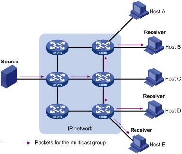
Unicast
In unicast, the information source (Source in the figure) needs to send a separate copy of information to each host (Receiver in the figure) that wants the information, as shown in Figure 1-1.
Figure 1-1 Unicast transmission
Assume that Hosts B, Host D and Host E need the information. A separate transmission channel needs to be established from the information source to each of these hosts.
In unicast transmission, the traffic transmitted over the network is proportional to the number of hosts that need the information. If a large number of users need the information, the information source needs to send a copy of the same information to each of these users. This means a tremendous pressure on the information source and the network bandwidth.
As we can see from the information transmission process, unicast is not suitable for batch transmission of information.
Broadcast
In broadcast, the information source sends information to all hosts on the subnet, even if some hosts do not need the information, as shown in Figure 1-2.
Figure 1-2 Broadcast transmission
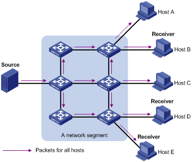
Assume that only Hosts B, Host D, and Host E need the information. If the information is broadcast to the subnet, Hosts A and Host C also receive it. In addition to information security issues, this also causes traffic flooding on the same subnet.
Therefore, broadcast is disadvantageous in transmitting data to specific hosts; moreover, broadcast transmission is a significant waste of network resources.
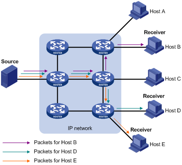
Multicast
As discussed above, unicast and broadcast techniques are unable to provide point-to-multipoint data transmissions with the minimum network consumption.
Multicast can well solve this problem. When some hosts on the network need multicast information, the information sender, or multicast source, sends only one copy of the information. Multicast distribution trees are built through multicast routing protocols, and the packets are replicated only on nodes where the trees branch. Figure 1-3 shows the delivery of a data stream to receiver hosts through multicast.
Figure 1-3 Multicast transmission
The multicast source (Source in the figure) sends only one copy of the information to a multicast group. Hosts B, Host D and Host E, which are receivers of the information, need to join the multicast group. The routers on the network duplicate and forward the information based on the distribution of the group members. Finally, the information is correctly delivered to Hosts B, Host D, and Host E.
To sum up, the advantages of multicast are summarized as follows:
l Over unicast: As multicast traffic flows to the node the farthest possible from the source before it is replicated and distributed, an increase of the number of hosts will not increase the load of the source and will not remarkably add to network resource usage.
l Over broadcast: As multicast data is sent only to the receivers that need it, multicast uses the network bandwidth reasonably and enhances network security. In addition, data broadcast is confined to the same subnet, while multicast is not.
Features of Multicast
Multicast has the following features:
l A multicast group is a multicast receiver set identified by an IP multicast address. Hosts join a multicast group to become members of the multicast group, before they can receive the multicast data addressed to that multicast group. Typically, a multicast source does not need to join a multicast group.
l An information sender is referred to as a multicast source (Source in Figure 1-3). A multicast source can send data to multiple multicast groups at the same time, and multiple multicast sources can send data to the same multicast group at the same time.
l All hosts that have joined a multicast group become members of the multicast group (Receiver in Figure 1-3). The group memberships are dynamic. Hosts can join or leave multicast groups at any time. Multicast groups are not subject to geographic restrictions.
l Routers or Layer 3 switches that support Layer 3 multicast are called multicast routers or Layer 3 multicast devices. In addition to providing the multicast routing function, a multicast router can also manage multicast group memberships on stub subnets with attached group members. A multicast router itself can be a multicast group member.
For a better understanding of the multicast concept, you can assimilate multicast transmission to the transmission of TV programs, as shown in Table 1-1.
Table 1-1 An analogy between TV transmission and multicast transmission
|
Step |
TV transmission |
Multicast transmission |
|
1 |
A TV station transmits a TV program through a channel. |
A multicast source sends multicast data to a multicast group. |
|
2 |
A user tunes the TV set to the channel. |
A receiver joins the multicast group. |
|
3 |
The user starts to watch the TV program transmitted by the TV station via the channel. |
The receiver starts to receive the multicast data that the source sends to the multicast group. |
|
4 |
The user turns off the TV set or tunes to another channel. |
The receiver leaves the multicast group or joins another group. |
Common Notations in Multicast
Two notations are commonly used in multicast:
l (*, G): Indicates a rendezvous point tree (RPT), or a multicast packet that any multicast source sends to multicast group G. Here “*” represents any multicast source, while “G” represents a specific multicast group.
l (S, G): Indicates a shortest path tree (SPT), or a multicast packet that multicast source S sends to multicast group G. Here “S” represents a specific multicast source, while “G” represents a specific multicast group.
![]()
For details about the concepts RPT and SPT, see PIM Configuration or IPv6 PIM Configuration in the IP Multicast Volume.
Advantages and Applications of Multicast
Advantages of multicast
Advantages of the multicast technique include:
l Enhanced efficiency: reduces the CPU load of information source servers and network devices.
l Optimal performance: reduces redundant traffic.
l Distributive application: enables point-to-multipoint applications at the price of minimum network resources.
Applications of multicast
Applications of the multicast technique include:
l Multimedia and streaming applications, such as Web TV, Web radio, and real-time video/audio conferencing.
l Communication for training and cooperative operations, such as distance learning and telemedicine.
l Data warehouse and financial applications (stock quotes).
l Any other point-to-multipoint data distribution application.
Multicast Models
Based on how the receivers treat the multicast sources, there are three multicast models: any-source multicast (ASM), source-filtered multicast (SFM), and source-specific multicast (SSM).
ASM model
In the ASM model, any sender can send information to a multicast group as a multicast source, and numbers of receivers can join a multicast group identified by a group address and obtain multicast information addressed to that multicast group. In this model, receivers are not aware of the position of multicast sources in advance. However, they can join or leave the multicast group at any time.
SFM model
The SFM model is derived from the ASM. From the view of a sender, the two models have the same multicast membership architecture.
The SFM model functionally extends the ASM model: In the SFM model, the upper layer software checks the source address of received multicast packets and permits or denies multicast traffic from specific sources. Therefore, receivers can receive the multicast data from only part of the multicast sources. From the view of a receiver, multicast sources are not all valid: they are filtered.
SSM model
In the practical life, users may be interested in the multicast data from only certain multicast sources. The SSM model provides a transmission service that allows users to specify the multicast sources they are interested in at the client side.
The radical difference between the SSM model and the ASM model is that in the SSM model, receivers already know the locations of the multicast sources by some other means. In addition, the SSM model uses a multicast address range that is different from that of the ASM/SFM model, and dedicated multicast forwarding paths are established between receivers and the specified multicast sources.
Multicast Architecture
IP multicast addresses the following questions:
l Where should the multicast source transmit information to? (multicast addressing)
l What receivers exist on the network? (host registration)
l Where is the multicast source the receivers need to receive multicast data from? (multicast source discovery)
l How should information be transmitted to the receivers? (multicast routing)
IP multicast falls in the scope of end-to-end service. The multicast architecture involves the following four parts:
1) Addressing mechanism: Information is sent from a multicast source to a group of receivers through a multicast address.
2) Host registration: Receiver hosts are allowed to join and leave multicast groups dynamically. This mechanism is the basis for group membership management.
3) Multicast routing: A multicast distribution tree (namely a forwarding path tree for multicast data on the network) is constructed for delivering multicast data from a multicast source to receivers.
4) Multicast applications: A software system that supports multicast applications, such as video conferencing, must be installed on multicast sources and receiver hosts, and the TCP/IP stack must support reception and transmission of multicast data.
Multicast Addresses
To allow communication between multicast sources and multicast group members, network-layer multicast addresses, namely, multicast IP addresses must be provided. In addition, a technique must be available to map multicast IP addresses to link-layer multicast MAC addresses.
IP multicast addresses
1) IPv4 multicast addresses
Internet Assigned Numbers Authority (IANA) assigned the Class D address space (224.0.0.0 to 239.255.255.255) for IPv4 multicast. The specific address blocks and usages are shown in Table 1-2.
Table 1-2 Class D IP address blocks and description
|
Address block |
Description |
|
224.0.0.0 to 224.0.0.255 |
Reserved permanent group addresses. The IP address 224.0.0.0 is reserved, and other IP addresses can be used by routing protocols and for topology searching, protocol maintenance, and so on. Common permanent group addresses are listed in Table 1-3. A packet destined for an address in this block will not be forwarded beyond the local subnet regardless of the Time to Live (TTL) value in the IP header. |
|
224.0.1.0 to 238.255.255.255 |
Globally scoped group addresses. This block includes two types of designated group addresses: l 232.0.0.0/8: SSM group addresses, and l 233.0.0.0/8: Glop group addresses. |
|
239.0.0.0 to 239.255.255.255 |
Administratively scoped multicast addresses. These addresses are considered to be locally rather than globally unique, and can be reused in domains administered by different organizations without causing conflicts. For details, refer to RFC 2365. |
![]()
l The membership of a group is dynamic. Hosts can join or leave multicast groups at any time.
l “Glop” is a mechanism for assigning multicast addresses between different autonomous systems (ASs). By filling an AS number into the middle two bytes of 233.0.0.0, you get 255 multicast addresses for that AS. For more information, refer to RFC 2770.
Table 1-3 Some reserved multicast addresses
|
Address |
Description |
|
224.0.0.1 |
All systems on this subnet, including hosts and routers |
|
224.0.0.2 |
All multicast routers on this subnet |
|
224.0.0.3 |
Unassigned |
|
224.0.0.4 |
Distance Vector Multicast Routing Protocol (DVMRP) routers |
|
224.0.0.5 |
Open Shortest Path First (OSPF) routers |
|
224.0.0.6 |
OSPF designated routers/backup designated routers |
|
224.0.0.7 |
Shared Tree (ST) routers |
|
224.0.0.8 |
ST hosts |
|
224.0.0.9 |
Routing Information Protocol version 2 (RIPv2) routers |
|
224.0.0.11 |
Mobile agents |
|
224.0.0.12 |
Dynamic Host Configuration Protocol (DHCP) server/relay agent |
|
224.0.0.13 |
All Protocol Independent Multicast (PIM) routers |
|
224.0.0.14 |
Resource Reservation Protocol (RSVP) encapsulation |
|
224.0.0.15 |
All Core-Based Tree (CBT) routers |
|
224.0.0.16 |
Designated Subnetwork Bandwidth Management (SBM) |
|
224.0.0.17 |
All SBMs |
|
224.0.0.18 |
Virtual Router Redundancy Protocol (VRRP) |
2) IPv6 multicast addresses
Figure 1-4 IPv6 multicast format

Referring to Figure 1-4, the meanings of the fields of an IPv6 multicast address are as follows:
l 0xFF: The most significant 8 bits are 11111111, indicating that this address is an IPv6 multicast address.
Figure 1-5 Format of the Flags field
![]()
l Flags: Referring to Figure 1-5. the following table describes the four bits of the Flags field.
Table 1-4 Description on the bits of the Flags fields
|
Bit |
Description |
|
0 |
Reserved, set to 0 |
|
R |
l When set to 0, it indicates that this address is an IPv6 multicast address without an embedded RP address l When set to 1, it indicates that this address is an IPv6 multicast address with an embedded RP address (The P and T bits must also be set to 1) |
|
P |
l When set to 0, it indicates that this address is an IPv6 multicast address not based on a unicast prefix l When set to 1, it indicates that this address is an IPv6 multicast address based on a unicast prefix (the T bit must also be set to 1) |
|
T |
l When set to 0, it indicates that this address is an IPv6 multicast address permanently-assigned by IANA l When set to 1, it indicates that this address is a transient, or dynamically assigned IPv6 multicast address |
l Scope: 4 bits, indicating the scope of the IPv6 internetwork for which the multicast traffic is intended. Possible values of this field are given in Table 1-5.
Table 1-5 Values of the Scope field
|
Meaning |
|
|
0, 3, F |
Reserved |
|
1 |
Interface-local scope |
|
2 |
Link-local scope |
|
4 |
Admin-local scope |
|
5 |
Site-local scope |
|
6, 7, 9 through D |
Unassigned |
|
8 |
Organization-local scope |
|
E |
Global scope |
l Group ID: 112 bits, IPv6 multicast group identifier that uniquely identifies an IPv6 multicast group in the scope defined by the Scope field.
Ethernet multicast MAC addresses
When a unicast IP packet is transmitted over Ethernet, the destination MAC address is the MAC address of the receiver. When a multicast packet is transmitted over Ethernet, however, the destination address is a multicast MAC address because the packet is directed to a group formed by a number of receivers, rather than to one specific receiver.
1) IPv4 multicast MAC addresses
As defined by IANA, the high-order 24 bits of an IPv4 multicast MAC address are 0x01005E, bit 25 is 0, and the low-order 23 bits are the low-order 23 bits of a multicast IPv4 address. The IPv4-to-MAC mapping relation is shown in Figure 1-6.
Figure 1-6 IPv4-to-MAC address mapping
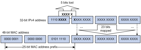
The high-order four bits of a multicast IPv4 address are 1110, indicating that this address is a multicast address, and only 23 bits of the remaining 28 bits are mapped to a MAC address, so five bits of the multicast IPv4 address are lost. As a result, 32 multicast IPv4 addresses map to the same MAC address. Therefore, in Layer 2 multicast forwarding, a device may receive some multicast data addressed for other IPv4 multicast groups, and such redundant data needs to be filtered by the upper layer.
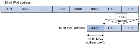
2) IPv6 multicast MAC addresses
The high-order 16 bits of an IPv6 multicast MAC address are 0x3333, and the low-order 32 bits are the low-order 32 bits of a multicast IPv6 address. Figure 1-7 shows an example of mapping an IPv6 multicast address, FF1E::F30E:101, to a MAC address.
Figure 1-7 An example of IPv6-to-MAC address mapping
Multicast Protocols
![]()
l Generally, we refer to IP multicast working at the network layer as Layer 3 multicast and the corresponding multicast protocols as Layer 3 multicast protocols, which include IGMP/MLD, PIM/IPv6 PIM, MSDP, and MBGP/IPv6 MBGP; we refer to IP multicast working at the data link layer as Layer 2 multicast and the corresponding multicast protocols as Layer 2 multicast protocols, which include IGMP Snooping/MLD Snooping, and multicast VLAN/IPv6 multicast VLAN.
l IGMP Snooping, IGMP, multicast VLAN, PIM, MSDP, and MBGP are for IPv4, MLD Snooping, MLD, IPv6 multicast VLAN, IPv6 PIM, and IPv6 MBGP are for IPv6.
This section provides only general descriptions about applications and functions of the Layer 2 and Layer 3 multicast protocols in a network. For details of these protocols, refer to the related configuration manuals in the IP Multicast Volume.
Layer 3 multicast protocols
Layer 3 multicast protocols include multicast group management protocols and multicast routing protocols. Figure 1-8 describes where these multicast protocols are in a network.
Figure 1-8 Positions of Layer 3 multicast protocols
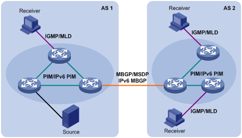
1) Multicast management protocols
Typically, the internet group management protocol (IGMP) or multicast listener discovery protocol (MLD) is used between hosts and Layer 3 multicast devices directly connected with the hosts. These protocols define the mechanism of establishing and maintaining group memberships between hosts and Layer 3 multicast devices.
2) Multicast routing protocols
A multicast routing protocol runs on Layer 3 multicast devices to establish and maintain multicast routes and forward multicast packets correctly and efficiently. Multicast routes constitute a loop-free data transmission path from a data source to multiple receivers, namely, a multicast distribution tree.
In the ASM model, multicast routes come in intra-domain routes and inter-domain routes.
l An intra-domain multicast routing protocol is used to discover multicast sources and build multicast distribution trees within an AS so as to deliver multicast data to receivers. Among a variety of mature intra-domain multicast routing protocols, protocol independent multicast (PIM) is a popular one. Based on the forwarding mechanism, PIM comes in two modes – dense mode (often referred to as PIM-DM) and sparse mode (often referred to as PIM-SM).
l An inter-domain multicast routing protocol is used for delivery of multicast information between two ASs. So far, mature solutions include multicast source discovery protocol (MSDP) and multicast border gateway protocol (MBGP). MSDP is used to propagate multicast source information among different ASs, while MBGP is an extension of the Multi-protocol Border Gateway Protocol (MP-BGP) is used for exchanging multicast routing information among different ASs.
For the SSM model, multicast routes are not divided into inter-domain routes and intra-domain routes. Since receivers know the position of the multicast source, channels established through PIM-SM are sufficient for multicast information transport.
Layer 2 multicast protocols
Layer 2 multicast protocols include IGMP Snooping/MLD Snooping and multicast VLAN/IPv6 multicast VLAN. Figure 1-9 shows where these protocols are in the network.
Figure 1-9 Position of Layer 2 multicast protocols
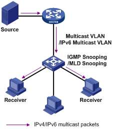
1) IGMP Snooping/MLD Snooping
Running on Layer 2 devices, Internet Group Management Protocol Snooping (IGMP Snooping) and Multicast Listener Discovery Snooping (MLD Snooping) are multicast constraining mechanisms that manage and control multicast groups by listening to and analyzing IGMP or MLD messages exchanged between the hosts and Layer 3 multicast devices, thus effectively controlling the flooding of multicast data in a Layer 2 network.
2) Multicast VLAN/IPv6 multicast VLAN
In the traditional multicast-on-demand mode, when users in different VLANs on a Layer 2 device need multicast information, the upstream Layer 3 device needs to forward a separate copy of the multicast data to each VLAN of the Layer 2 device. With the multicast VLAN or IPv6 multicast VLAN feature enabled on the Layer 2 device, the Layer 3 multicast device needs to send only one copy of multicast to the multicast VLAN or IPv6 multicast VLAN on the Layer 2 device. This avoids waste of network bandwidth and extra burden on the Layer 3 device.
Multicast Packet Forwarding Mechanism
In a multicast model, a multicast source sends information to the host group identified by the multicast group address in the destination address field of IP multicast packets. Therefore, to deliver multicast packets to receivers located in different parts of the network, multicast routers on the forwarding path usually need to forward multicast packets received on one incoming interface to multiple outgoing interfaces. Compared with a unicast model, a multicast model is more complex in the following aspects.
l To ensure multicast packet transmission in the network, unicast routing tables or multicast routing tables (for example, the MBGP routing table) specially provided for multicast must be used as guidance for multicast forwarding.
l To process the same multicast information from different peers received on different interfaces of the same device, every multicast packet is subject to a reverse path forwarding (RPF) check on the incoming interface. The result of the RPF check determines whether the packet will be forwarded or discarded. The RPF check mechanism is the basis for most multicast routing protocols to implement multicast forwarding.
![]()
For details about the RPF mechanism, refer to Multicast Routing and Forwarding Configuration or IPv6 Multicast Routing and Forwarding Configuration in the IP Multicast Volume.
Multi-Instance Multicast
Multi-instance multicast refers to multicast in virtual private networks (VPNs).
Introduction to the Multi-Instance Concept
VPN networks need to be isolated from one another and from the public network. As shown in Figure 1-10, VPN A and VPN B separately access the public network through PE devices.
Figure 1-10 Networking diagram for VPN
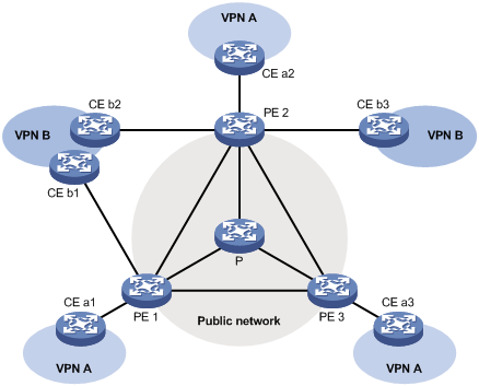
l The P device belongs to the public network. The CE devices belong to their respective VPNs. Each CE device serves its own network and maintains only one set of forwarding mechanism.
Multi-Instance Application in Multicast
With multi-instance multicast enabled, a PE is able to:
l Maintain a set of independent multicast forwarding mechanism for each instance, include various multicast protocols, a list of PIM neighbors and a multicast routing table per instance. Each instance searches its own forwarding table or routing table to forward multicast data.
l Guarantee the isolation between different VPN instances.
l Implement information exchange and data conversion between the public instance and VPN instances.
Multi-instance multicast is the basis of multicast over a VPNs network. With multicast VPN, as shown in Figure 1-10, when a multicast source in VPN A sends a multicast stream to a multicast group, of all possible receivers on the network for that group, only those belong to VPN A can receive the multicast stream. The multicast data is multicast both in VPN A and in the public network.
![]()
l Only one set of unified multicast service runs on a non-PE device. It is called public instance.
l The configuration made in VPN instance view only takes effect on the VPN instance interface only. An interface that does not belong to any VPN instance is called public instance interface.
l For more information about multicast VPN, refer to Multicast VPN Configuration in the IP Multicast Volume.
