- Table of Contents
-
- 04-IP Multicast Volume
- 00-IP Multicast Volume Organization
- 01-Mulitcast Overview
- 02-Multicast Routing and Forwarding Configuration
- 03-IGMP Configuration
- 04-PIM Configuration
- 05-MSDP Configuration
- 06-MBGP Configuration
- 07-Multicast VPN Configuration
- 08-IGMP Snooping Configuration
- 09-Multicast VLAN Configuration
- 10-IPv6 Multicast Routing and Forwarding Configuration
- 11-MLD Configuration
- 12-IPv6 PIM Configuration
- 13-IPv6 MBGP Configuration
- 14-MLD Snooping Configuration
- 15-IPv6 Multicast VLAN Configuration
- Related Documents
-
| Title | Size | Download |
|---|---|---|
| 07-Multicast VPN Configuration | 494.14 KB |
MD-VPN Configuration Task List
Enabling IP Multicast Routing in a VPN Instance
Configuring a Share-Group and an MTI Binding
Displaying and Maintaining MD-VPN
Single-AS MD VPN Configuration
Troubleshooting MD-VPN Configuration
Unable to Establish a Share-MDT
When configuring multicast VPN, go to the following sections for the information you are interested in:
l MD-VPN Configuration Task List
l Displaying and Maintaining MD-VPN
l MD VPN Configuration Examples
l Troubleshooting MD-VPN Configuration
Multicast VPN Overview
Introduction to MPLS L3VPN
![]()
l For details about MPLS L3VPN, refer to MPLS L3VPN Configuration in the MPLS Volume.
l For details about BGP, refer to BGP Configuration in the IP Routing Volume.
Multicast VPN is a technique that implements multicast delivery in MPLS L3VPN networks. An MPLS L3VPN is a virtual private network (VPN) implemented based on the extension technologies of the Border Gateway Protocol (BGP) and Multiprotocol Label Switching (MPLS). It comprises a set of customer sites that are interconnected only by means of an MPLS provider backbone network. The VPN can be regarded as a set of policies that control the interconnections between these sites.
Figure 1-1 Typical application of MPLS L3VPNs
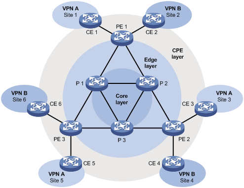
As shown in Figure 1-1, VPN A comprises Site 1, Site 3 and Site 5, while VPN B comprises Site 2, Site 4 and Site 6. A VPN involves the following three types of devices:
l Provider (P) device: device in the core of the provider backbone network. A P device does not directly interface with CE devices, but it implements MPLS forwarding.
l Provider edge (PE) device: edge device in the provider backbone network. Directly interfacing with one or more CE devices, a PE device processes VPN routing as a main MPLS L3VPN implementer.
l Customer edge (CE) device: edge device on a customer network. A CE device can be a router, a switch, or a host, that implements route distribution on the customer network.
In an MPLS L3VPN environment, between any two sites that belong to the same VPN, packets are transmitted labeled across the public network. The PE device at the entrance to the provider backbone attaches two labels to the packets, one inner label and the other outer label:
l Outer label: the label used for switching within the backbone, representing a label switched path (LSP) from the local PE to the peer PE. With this label, a packet can arrive to the peer PE along the LSP.
l Inner label: The inner label represents an LSP between two CE devices interconnected over the backbone network. It identifies the site to which the packet belongs. The PE forwards the packet to the target CE based on the inner label.
Introduction to Multicast VPN
Figure 1-2 shows an example of multicast over an MPLS VPNs network, which carries three independent multicast services – the public instance, VPN instance A, and VPN instance B. A PE multicast device at the edge of the public network supports multiple instances, equivalent to multiple independent multicast devices. Each instance corresponds to a plane, and all these planes are isolated from one another. For example, Figure 1-2, shows three instances that are running on PE1: They are the public instance, VPN instance A, and VPN instance B. These three instances can be regarded as three independent virtual devices, which are PE 1’, PE 1”, and PE 1’”, each virtual device corresponding to a plane, as shown in Figure 1-2.
Figure 1-2 Multicast in multiple VPN instances
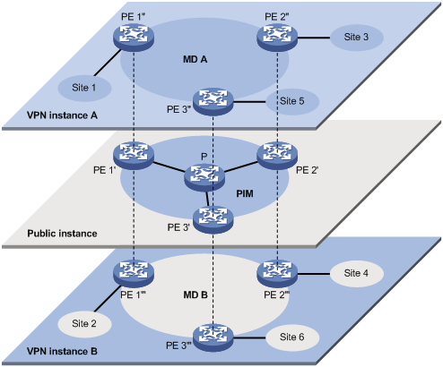
With multicast VPN, when a multicast source in VPN A sends a multicast stream to a multicast group, of all possible receivers on the network for that group, only those belong to VPN A, namely in Site 1, Site 3 or Site 5, can receive the multicast stream. The stream is multicast in these sites and in the public network.
The prerequisites for implementing multicast VPN are as follows:
1) The support for VPN instance based multicast within each site,
2) The support for public instance based multicast within the public network, and
3) PE devices that support multi-instance multicast:
l Interfacing with sites and supporting VPN instance based multicast,
l Interfacing with the public network and supporting public instance based multicast, and
l Supporting information exchange and data conversion between the public instance and the VPN instances.
Introduction to MD-VPN
![]()
For details about the concepts of Protocol Independent Multicast (PIM), bootstrap router (BSR), candidate-BSR (C-BSR), rendezvous point (RP), candidate RP (C-RP), shortest path tree (SPT) and rendezvous point tree (RPT), refer to PIM Configuration in the IP Multicast Volume.
S7500E series switches implements multicast VPN by means of the multicast domain (MD) method. This multicast VPN implementation is referred to as MD-VPN.
Basic concepts in MD-VPN
The basic concepts involved in MD-VPN are described in Table 1-1.
Table 1-1 Basic concepts in MD-VPN
|
Concept |
Description |
|
Multicast domain (MD) |
An MD is a set of interconnected MVRFs. Each MD uniquely corresponds to a multicast-capable VPN, and all the PE devices interfacing with this VPN belong to this MD. |
|
Multicast distribution tree (MDT) |
An MDT is a multicast distribution tree between all PE devices in the same VPN. There is one kind of MDT: share-MDT. |
|
Multicast tunnel (MT) |
An MT is a tunnel that interconnects all MVRFs in an MD for delivering private network traffic within the MD. |
|
Multicast tunnel interface (MTI) |
An MTI is the entrance to or exit of an MT, equivalent to an entrance to or exit of an MD. An MTI handles only multicast packets but not unicast packets. An MTI is automatically created with the configuration of a share-group and MTI binding for a VPN instance. An MVRF uses the MTI to access the MD. In the perspective of an MVRF, an MTI is like a LAN interface, while the MD is like a LAN network, to which all the PE devices are attached. |
|
Multicast VPN routing and forwarding (MVRF) |
With Layer 3 multicast enabled, a VPN instance also maintains its multicast routing and forwarding table. The unicast routing and forwarding table and the multicast router and forwarding table for the same VPN instance are referred to as an MVRF in general. MVRFs on different PEs join the same MD and are interconnected by means of the multicast tunnel (MT) automatically established in the MD to enable multicast service between different sites and form a multicast VPN network. |
|
Share-group |
In the public network, each MD is assigned an independent multicast address, called share-group. A share-group is the unique identifier of an MD in the public network. It is used to build a share-MDT corresponding to the MD in the public network. |
|
Share-multicast distribution tree (Share-MDT) |
A share-MDT is an MDT that uses a share-group as its group address. In a VPN, the share-MDT is uniquely identified by the share-group. A share-MDT is automatically created after configuration and will always exist in the public network, regardless of the presence of any actual multicast services in the public network or the VPN. |
|
VPN routing and forwarding (VRF) |
Each VPN instance maintains its unicast routing and forwarding table, which is referred to as VRF. |
Introduction to MD-VPN
Main points in the implementation of MD-VPN are as follows:
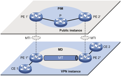
2) Logically, an MD defines the transmission range of the multicast traffic of a specific VPN over the public network; physically, an MD identifies all the PE devices that support that VPN in the public network. Different VPN instances correspond to different MDs. As shown in Figure 1-3, the ellipse area in the center of each VPN instance plane represents an MD, which serves that particular VPN. All the private network multicast traffic in that VPN is transmitted within that MD.
3) Inside an MD, all the private traffic is transmitted through the MT. The process of multicast traffic transmission through an MT is as follows: the local PE device encapsulates the private network data into a public network packet, which is then forwarded in the public network, and the remote PE device decapsulates the packet to turn it back into a private packet.
4) The local PE device sends out private network data through the MTI, and the remote PE devices receive the private data through the MTI. As shown in Figure 1-3, an MD can be thought of as a private data transmission pool, and an MTI can be thought of an entrance/exit of the pool. The local PE device puts the private data into the transmission pool (the MD) through the entrance (MTI), and the transmission pool automatically duplicates the private data and transmits the data to each exit (MTI) of the transmission pool, so that any remote PE device that needs the data can get it from the respective exit (MTI).
Figure 1-3 Relationship between PIM in the public instance and an MD in a VPN instance
5) Each VPN instance is assigned a unique share-group address. The private network data is transparent to the public network. A PE device encapsulates any private network multicast packet within a normal public network multicast packet, no matter what multicast group the private network packet is destined for and whether it is a protocol packet or a data packet, and uses the share-group as the public network multicast group for the packet. Then, the PE sends the public network multicast packet onto the public network.
6) A share-group corresponds to a unique MD; for each share-group, a unique share-MDT is constructed by leveraging the public network resources for multicast data forwarding. All the private network multicast packets transmitted in this VPN are forwarded along this share-MDT, no matter at which PE device they entered the public network.
PIM neighboring relationships in MD-VPN
Figure 1-4 PIM neighboring relationships in MD-VPN
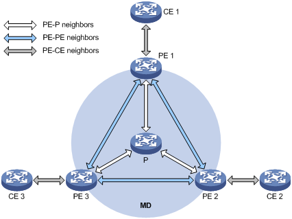
PIM neighboring relationships are established between two or more directly interconnected devices on the same subnet. As shown in Figure 1-4, there are three types of PIM neighboring relationships in MD-VPN, as follows:
l PE-P neighboring relationship: PIM neighboring relationship established between the public instance interface on a PE device and an interface on the P device across the link.
l PE-PE neighboring relationship: PIM neighboring relationship established after a VPN instance on a PE device receives a PIM hello from a VPN instance on a remote PE device through an MTI.
l PE-CE neighboring relationship: PIM neighboring relationship established between a VPN-instance-associated interface on a PE device and an interface on a peer CE device.
Protocols and Standards
The protocols/standards related to multicast VPN are as follows:
l RFC 4684: Constrained Route Distribution for Border Gateway Protocol/MultiProtocol Label Switching (BGP/MPLS) Internet Protocol (IP) Virtual Private Networks (VPNs)
l draft-rosen-vpn-mcast-08: Multicast in MPLS/BGP IP VPNs
How MD-VPN Works
This section describes the implementation principle of the MD-VPN technology, including establishment of a share-MDT, packet delivery over it, and implementation of multi-AS MD-VPN.
For a VPN instance, multicast data transmission in the public network is transparent. The MTIs at the local PE device and the remote PE device form a channel for the seamless transmission of private network data over the public network. All that is known to the VPN instance is that the VPN data is sent out the MTI and then the remote site can receive the data through the MTI. Actually, the multicast data transmission process (the MDT transmission process) over the public network is very complicated.
Share-MDT Establishment
Share-MDT establishment in a PIM-DM network
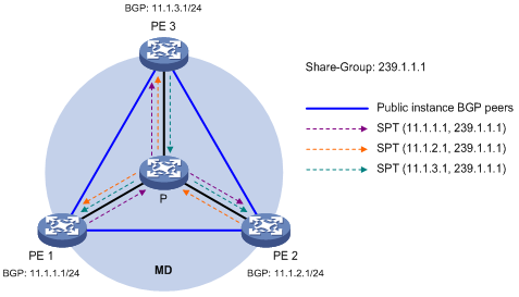
Figure 1-5 Share-MDT establishment in a PIM-DM network

As shown in Figure 1-5, PIM-DM is enabled in the network and all the PE devices support VPN instance A. The process of establishing a share-MDT is as follows:
The public instance on PE 1 initiates a flood-prune process in the entire public network, with the BGP interface address (namely the interface address used to establish the BGP peer) as the multicast source address and the share-group address as the multicast group address. All the other PE devices that are running VPN instance A are group members, so that a (11.1.1.1, 239.1.1.1) state entry is created on each device along the path in the public network. This forms an SPT with PE 1 as the root, and PE 2 and PE 3 as leaves.
At the same time, PE 2 and PE 3 respectively initiate a similar flood-prune process. Finally, three independent SPTs are established in the MD. In the PIM-DM network, these independent SPTs constitute a share-MDT.
Share-MDT establishment in a PIM-SM network
Figure 1-6 Share-MDT establishment in a PIM-SM network
As shown in,Figure 1-6 PIM-SM is enabled in the network and all the PE devices support VPN instance A. The process of establishing a share-MDT is as follows:
1) The public instance on PE 1 initiates a join to the public network RP, with the share-group address as the multicast group address in the join message, and a (*, 239.1.1.1) state entry is created on each device along the path in the public network. At the same time, PE 2 and PE 3 respectively initiate a similar join process. Finally, an RPT is established in the MD, with the public network RP as the root and PE 1, PE 2 and PE 3 as leaves.
2) The public instance on PE 1 registers the multicast source with the public network RP, with the BGP interface address as the multicast source address and the share-group address as the multicast group address in the register message, and a (11.1.1.1, 239.1.1.1) state entry is created on each device along the path in the public network. At the same time, PE 2 and PE 3 respectively initiate a similar register process. Finally, three SPTs between the PE devices and the RP are established in the MD.
In the PIM-SM network, the RPT, namely the (*, 239.1.1.1) tree, and the three independent SPTs constitute a share-MDT.
Share-MDT establishment in a PIM-SSM network
Figure 1-7 Share-MDT establishment in a PIM-SSM network
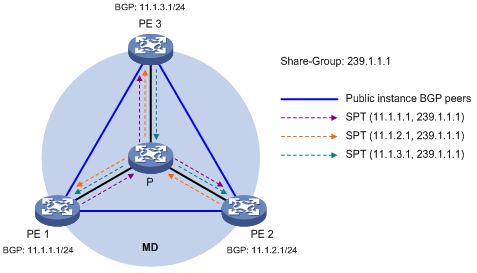
As shown in Figure 1-7, PIM-SSM is enabled in the network and all the PE devices support VPN instance A. The process of establishing a share-MDT is as follows:
The public instance on PE 1 sends the local BGP MDT routing information, including its BGP interface address and the share-group address, to PE 2 and PE 3. PE 2 and PE 3 perform the same operation to exchange their BGP MDT routing information with one another. Upon receiving the BGP MDT information from PE1, PE 2 and PE 3 respectively send a subscribe message for channel subscription hop by hop toward the BGP interface of PE1. A (11.1.1.1, 232.1.1.1) entry is created on devices on the path toward PE 1 in the public network. Thus an SPT is created in the network, with PE 1 as its root, PE 2 and PE 3 as its leaves.
At the same time, PE 2 and PE 3 respectively initiate a similar SPT establishment process. Finally, three independent SPTs are established in the MD. In the PIM-SS M network, the three independent SPTs constitute a share-MDT.
Characteristics of a share-MDT
As discussed above, a share-MDT is characterized as follows, no matter what PIM mode is running in the public network:
l All PE devices that support this VPN instance (PE 1, PE 2, and PE 3 in this example) join the share-MDT.
Share-MDT-Based Delivery
A share-MDT can be used for delivering multicast packets, including both multicast protocol packets and multicast data packets. However, the transmission processes for these two types of multicast packets are different.
Delivery of multicast protocol packets
Where a multicast source and the receivers are located in different sites of a VPN, multicast protocol packets must be transmitted across the public network. Protocol packets are encapsulated into normal multicast data packets for the public network on the local PE device, transmitted along the share-MDT, and then decapsulated on the remote PE device to go into the normal protocol procedure. Finally a distribution tree is established across the public network.
![]()
All interfaces that belong to the same VPN, including those interfaces with VPN instance bindings and the MTI on PE devices, must run the same PIM mode.
1) If PIM-DM or PIM-SSM is running in the VPNs network, SPTs need to be created across the public network.
2) On a VPNs network running PIM-SM:
l If the receivers and the VPN RP are in different sites, joins need to be initiated across the public network to establish an RPT.
l If the multicast source and the VPN RP are in different sites, registrations need to be initiated across the public network to establish SPTs.
![]()
The following example explains how multicast protocol packets are delivered based on the share-MDT while PIM-SM is running in both the public network and the VPNs network, with receivers and the VPN RP located in different sites.
As shown in Figure 1-8, PIM-SM is running in both the public network and the VPNs network, Receiver for the VPN multicast group G (225.1.1.1) in Site 2 is attached to CE 2, while CE 1 of Site 1 acts as the RP for group G (225.1.1.1); the share-group address used to forward public network data is 239.1.1.1.
Figure 1-8 Transmission of multicast protocol packets
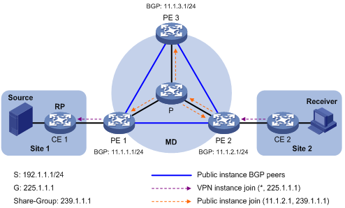
The work process of multicast protocol packets is as follows:
1) Receiver sends an IGMP membership report for multicast group G to CE 2. CE 2 creates a local (*, 225.1.1.1) state entry and sends a join message to the VPN RP (CE 1).
2) Upon receiving the join message from CE 2, the VPN instance on PE 2 creates a (*, 225.1.1.1) state entry with the upstream interface being the MTI, and then PE 2 processes the join message. Now, the VPN instance on PE 2 considers that the join message has been sent out the MTI.
3) PE 2 encapsulates the join message by means of Generic Routing Encapsulation (GRE), with its BGP interface address as the multicast source address and the share-group address as the multicast group address, to convert it into a normal, public network multicast data packet (11.1.2.1, 239.1.1.1), and then passes the packet to the public instance on PE 2 to have it forwarded to the public network.
4) The multicast data packet (11.1.2.1, 239.1.1.1) is forwarded to the public instance on all the PE devices along the share-MDT. Upon receiving this packet, every PE device decapsulates it to turn it back into a join message to be sent to the VPN RP. Then, each PE device checks the join message. If any PE device finds that the VPN RP is in the site it interfaces with, it passes the join message to the VPN instance on it; otherwise, it discards the join message.
5) When receiving the join message, the VPN instance on PE 1 considers that it received the message from the MTI. PE 1 creates a local (*, 225.1.1.1) state entry, with the downstream interface being the MTI and the upstream interface being the one that leads to CE 1. At the same time, it sends a join message to CE 1, which is the VPN RP.
6) Upon receiving the join message from the VPN instance on PE 1, CE 1 creates a local (*, 225.1.1.1) state entry or updates the entry if it already exists. By now, the construction of an RPT across the public network is completed.
Delivery of multicast data packets
After the share-MDT is established, the private network multicast data flows to the receivers in each site along the distribution tree. The private network multicast packets are encapsulated into normal public network multicast packets on the local PE device, transmitted along the share-MDT, and then decapsulated on the remote PE device and transmitted in the private network.
1) If IPIM-DM or PIM-SSM is running in the VPNs network, the customer multicast traffic flows along the SPTs across the public network..
2) On a VPNs network running PIM-SM (before RPT-to-SPT switchover only):
l If the receivers and the VPN RP are in different sites, the customer multicast traffic flows along the RPT across the public network.
l If the multicast source and the VPN RP are in different sites, the customer multicast traffic flows along the SPTs across the public network.
![]()
l For detailed description of RPT-to-SPT switchover, refer to PIM Configuration in the IP Multicast Volume.
l The following example explains how multicast data packets are delivered based on the share-MDT while PIM-DM is running in both the public network and the VPNs network.
As shown in Figure 1-9, PIM-DM is running in both the public network and the VPNs network, Receiver of the VPN multicast group G (225.1.1.1) in Site 2 is attached to CE 2, and Source in Site 1 sends multicast data to multicast group G); the share-group address used to forward public network multicast data is 239.1.1.1.
Figure 1-9 Delivery of multicast data packets
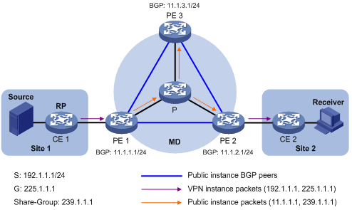
The private network multicast traffic is delivered across the public network as follows.
1) Source sends customer multicast data (192.1.1.1, 225.1.1.1) to CE 1.
2) CE 1 forwards the private network multicast data along an SPT to CE 1, and the VPN instance on PE 1 checks the MVRF. If the outgoing interface list of the forwarding entry contains an MTI, PE 1 processes the private network multicast data. Now, the VPN instance on PE 1 considers that the private network multicast data has been sent out the MTI.
3) PE 1 encapsulates the multicast data by means of GRE, with its BGP interface address as the multicast source address and the share-group address as the multicast group address, to convert it into a normal, public network multicast data packet (11.1.1.1, 239.1.1.1), and then passes the packet to the public instance on PE 1 to have it forwarded to the public network.
4) The multicast data packet (11.1.1.1, 239.1.1.1) is forwarded to the public instance on all the PE devices along the share-MDT. Upon receiving this packet, every PE device decapsulates it to turn it back into a private network multicast data packet, and passes it to the corresponding VPN instance. If any PE has a downstream interface for an SPT, it forwards the private network multicast packet down the SPT; otherwise, it discards the packet.
MD-VPN Configuration Task List
Complete these tasks to configure MD-VPN:
|
Task |
Remarks |
|
Required |
|
Configuring MD-VPN
Configuration Prerequisites
Before configuring MD-VPN, complete the following tasks:
l Configure any unicast routing protocol to provide intra-domain interoperability at the network layer.
l Enable PIM (PIM-DM ,PIM-SM or PIM-SSM).
Before configuring MD-VPN, prepare the following data:
l VPN instance names and route distinguishers (RDs)
l Share-group addresses and an MTI numbers
Enabling IP Multicast Routing in a VPN Instance
Before configuring any MD-VPN functionality for a VPN, you must enable IP multicast routing in the VPN instance.
Follow these steps to enable IP multicast routing in a VPN instance:
|
To do.... |
Use the command.... |
Remarks |
|
Enter system view |
system-view |
— |
|
Create a VPN instance and enter VPN instance view |
ip vpn-instance vpn-instance-name |
— |
|
Configure an RD for the VPN instance |
route-distinguisher route-distinguisher |
Required No RD is configured for a VPN instance by default. |
|
Enable IP multicast routing |
multicast routing-enable |
Required |
l For details about the ip vpn-instance and route-distinguisher commands, refer to MPLS L3VPN Commands in the MPLS Volume.
l For details about the multicast routing-enable command, refer to Multicast Routing and Forwarding Commands in the IP Multicast Volume.
Configuring a Share-Group and an MTI Binding
By running multiple instances on each PE device, you enable the PE device to work for multiple VPNs. You need to configure the same share-group address for the same VPN instance on different PE devices. With a share-group and an MTI number configured, the system automatically creates an MTI, binds the share-group address to the MTI and binds the MTI to the current VPN instance.
Follow these steps to configure a share-group and an MTI binding:
|
To do.... |
Use the command.... |
Remarks |
|
Enter system view |
system-view |
— |
|
Enter VPN instance view |
ip vpn-instance vpn-instance-name |
— |
|
Configure a share-group address and an MTI binding |
multicast-domain share-group group-address binding mtunnel mtunnel-number |
Required No share-group address or MTI binding is configured. |
l After a BGP peer is configured with the peer connect-interface command, the MTI interface automatically obtains the connect-interface address and uses it as its own IP address. This IP address cannot be used in the VPNs network any more; otherwise the MTI interface will fail to obtain an IP address. When configuring multiple BGP peers on the same device, you must specify the same connect-interface address for these BGP peers; otherwise the MTI interface will also fail to obtain an IP address, either. For details about the peer connect-interface command, refer to BGP Commands in the IP Routing Volume.
l The MTI interface becomes up only after it obtains an IP address. You need to use the service-loopback group command to configure a multicast-tunnel type service loopback group before an MTI interface can be brought up. For details about the service-loopback group command, refer to Service Lookback Commands in the Access Volume.
l PIM on the MTI interface takes effect only after PIM is enabled on at least one interface of the VPN instance; when PIM is disabled on all the interfaces of the VPN instance, PIM on the MTI interface is disabled simultaneously.
Displaying and Maintaining MD-VPN
|
To do.... |
Use the command.... |
Remarks |
|
View the share-group information of the specified VPN instance in the MD |
display multicast-domain vpn-instance vpn-instance-name share-group |
Available in any view |
MD VPN Configuration Examples
Single-AS MD VPN Configuration
Network requirements
The network requirements for single-AS MD-VPN configuration are listed in the table below:
|
Item |
Network requirements |
|
Multicast sources and receivers |
l In VPN a, S 1 is a multicast source, and R 1, R 2 and R3 are receivers. l In VPN b, S 2 is a multicast source, and R 4 is a receiver. l For VPN a, the share-group address is 239.1.1.1. l For VPN b, the share-group address is 239.2.2.2. |
|
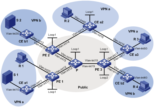
PE interfaces and VPN instances they belong to |
l PE 1: VLAN-interface 11 and VLAN-interface 20 belong to VPN instance a; VLAN-interface 12 and Loopback 1 belong to the public network instance. l PE 2: VLAN-interface 13 belongs to VPN instance b; VLAN-interface 14 belongs to VPN instance a; VLAN-interface 15 and Loopback 1 belong to the public network instance. l PE 3: VLAN-interface 17 belongs to VPN instance a; VLAN-interface 18 and Loopback 2 belong to VPN instance b; VLAN-interface 19 and Loopback 1 belong to the public network instance. |
|
Unicast routing protocols and MPLS |
l Configure OSPF in the public network, and configure RIP between the PEs and CEs. l Establish BGP peer connections between PE 1, PE 2 and PE 3 on their respective Loopback 1 interface and exchange all private network routes between them. l Configure MPLS in the public network. |
|
IP multicast routing |
l Enable IP multicast routing on the P device. l Enable IP multicast routing in the public instance on PE 1, PE 2, and PE 3. l Enable IP multicast routing in VPN instance a on PE 1, PE 2, and PE 3. l Enable IP multicast routing in VPN instance b on PE 2 and PE 3. l Enable IP multicast routing on CE a1, CE a2, CE a3, CE b1, and CE b2. |
|
IGMP |
l Run IGMPv2 on VLAN-interface 20 of PE 1. l Run IGMPv2 on VLAN-interface 40 of CE a2, VLAN-interface 50 of CE a3, and VLAN-interface 60 of CE b2. |
|
PIM |
l Enable PIM-SM on all interfaces of the P device. l Enable PIM-SM on all public and private network interfaces of PE 1, PE 2 and PE 3. l Enable PIM-SM on all interfaces of CE a1, CE a2, CE a3, CE b1, and CE b2. l Configure Loopback 1 of P as a C-BSR and a C-RP for the public network (to work for all multicast groups). l Configure Loopback 1 of CE a2 as a C-BSR and a C-RP for VPN a (to work for all multicast groups). l Configure Loopback 2 of PE 3 as a C-BSR and a C-RP for VPN b (to work for all multicast groups). |
Network diagram
Figure 1-10 Network diagram for single-AS MD VPN configuration
|
Device |
Interface |
IP address |
Device |
Interface |
IP address |
|
S 1 |
— |
10.110.7.2/24 |
PE 3 |
Vlan-int19 |
192.168.8.1/24 |
|
S 2 |
— |
10.110.8.2/24 |
|
Vlan-int17 |
10.110.5.1/24 |
|
R 1 |
— |
10.110.1.2/24 |
|
Vlan-int18 |
10.110.6.1/24 |
|
R 2 |
— |
10.110.9.2/24 |
|
Loop1 |
1.1.1.3/32 |
|
R 3 |
— |
10.110.10.2/24 |
|
Loop2 |
33.33.33.33/32 |
|
R 4 |
— |
10.110.11.2/24 |
CE a1 |
Vlan-int10 |
10.110.7.1/24 |
|
P |
Vlan-int12 |
192.168.6.2/24 |
|
Vlan-int11 |
10.110.2.2/24 |
|
|
Vlan-int15 |
192.168.7.2/24 |
CE a2 |
Vlan-int40 |
10.110.9.1/24 |
|
|
Vlan-int19 |
192.168.8.2/24 |
|
Vlan-int14 |
10.110.4.2/24 |
|
|
Loop1 |
2.2.2.2/32 |
|
Vlan-int16 |
10.110.12.1/24 |
|
PE 1 |
Vlan-int12 |
192.168.6.1/24 |
|
Loop1 |
22.22.22.22/32 |
|
|
Vlan-int20 |
10.110.1.1/24 |
CE a3 |
Vlan-int50 |
10.110.10.1/24 |
|
|
Vlan-int11 |
10.110.2.1/24 |
|
Vlan-int17 |
10.110.5.2/24 |
|
|
Loop1 |
1.1.1.1/32 |
|
Vlan-int16 |
10.110.12.2/24 |
|
PE 2 |
Vlan-int15 |
192.168.7.1/24 |
CE b1 |
Vlan-int30 |
10.110.8.1/24 |
|
|
Vlan-int13 |
10.110.3.1/24 |
|
Vlan-int13 |
10.110.3.2/24 |
|
|
Vlan-int14 |
10.110.4.1/24 |
CE b2 |
Vlan-int60 |
10.110.11.1/24 |
|
|
Loop1 |
1.1.1.2/32 |
|
Vlan-int18 |
10.110.6.2/24 |
Configuration procedure
1) Configure PE 1
# Configure a Router ID, enable IP multicast routing in the public instance, configure an MPLS LSR ID, and enable the LDP capability.
<PE1> system-view
[PE1] router id 1.1.1.1
[PE1] multicast routing-enable
[PE1] mpls lsr-id 1.1.1.1
[PE1] mpls
[PE1-mpls] quit
[PE1] mpls ldp
[PE1-mpls-ldp] quit
# Create VPN instance a, configure a RD for it, and create an egress route and an ingress route for it.
[PE1] ip vpn-instance a
[PE1-vpn-instance-a] route-distinguisher 100:1
[PE1-vpn-instance-a] vpn-target 100:1 export-extcommunity
[PE1-vpn-instance-a] vpn-target 100:1 import-extcommunity
# Enable IP multicast routing in VPN instance a, configure a share-group address associate an MTI with the VPN instance.
[PE1-vpn-instance-a] multicast routing-enable
[PE1-vpn-instance-a] multicast-domain share-group 239.1.1.1 binding mtunnel 0
[PE1-vpn-instance-a] quit
# Configure an IP address, and enable PIM-SM and LDP capability on the public network interface VLAN-interface 12.
[PE1] interface vlan-interface 12
[PE1-Vlan-interface12] ip address 192.168.6.1 24
[PE1-Vlan-interface12] pim sm
[PE1-Vlan-interface12]] mpls
[PE1-Vlan-interface12] mpls ldp
[PE1-Vlan-interface12] quit
# Bind VLAN-interface 20 to VPN instance a, configure an IP address and enable IGMP and PIM-SM on the interface.
[PE1] interface vlan-interface 20
[PE1-Vlan-interface20] ip binding vpn-instance a
[PE1-Vlan-interface20] ip address 10.110.1.1 24
[PE1-Vlan-interface20] igmp enable
[PE1-Vlan-interface20] pim sm
[PE1-Vlan-interface20] quit
# Bind VLAN-interface 11 to VPN instance a, configure an IP address and enable PIM-SM on the interface.
[PE1] interface vlan-interface 11
[PE1-Vlan-interface11] ip binding vpn-instance a
[PE1-Vlan-interface11] ip address 10.110.2.1 24
[PE1-Vlan-interface11] pim sm
[PE1-Vlan-interface11] quit
# Configure an IP address for Loopback 1, and enable PIM-SM.
[PE1] interface loopback 1
[PE1-LoopBack1] ip address 1.1.1.1 32
[PE1-LoopBack1] pim sm
[PE1-LoopBack1] quit
# Configure BGP.
[PE1] bgp 100
[PE1-bgp] group vpn-g internal
[PE1-bgp] peer vpn-g connect-interface loopback 1
[PE1-bgp] peer 1.1.1.2 group vpn-g
[PE1-bgp] peer 1.1.1.3 group vpn-g
[PE1–bgp] ipv4-family vpn-instance a
[PE1-bgp-a] import-route rip 2
[PE1-bgp-a] import-route direct
[PE1-bgp-a] quit
[PE1–bgp] ipv4-family vpnv4
[PE1–bgp-af-vpnv4] peer vpn-g enable
[PE1-bgp-af-vpnv4] peer 1.1.1.2 group vpn-g
[PE1–bgp-af-vpnv4] peer 1.1.1.3 group vpn-g
[PE1–bgp-af-vpnv4] quit
[PE1–bgp] quit
With BGP peers configured on PE 1, the interfaces MTI 0 will automatically obtain an IP address, which is the loopback interface address specified in the BGP peer configuration. The PIM mode running on MTI 0 is the same as on the interfaces in VPN instance a.
# Configure OSPF.
[PE1] ospf 1
[PE1-ospf-1] area 0.0.0.0
[PE1-ospf-1-area-0.0.0.0] network 1.1.1.1 0.0.0.0
[PE1-ospf-1-area-0.0.0.0] network 192.168.0.0 0.0.255.255
[PE1-ospf-1-area-0.0.0.0] quit
[PE1-ospf-1] quit
# Configure RIP
[PE1] rip 2 vpn-instance a
[PE1-rip-2] network 10.0.0.0
[PE1-rip-2] import-route bgp
[PE1-rip-2] return
2) Configure PE 2
# Configure a Router ID, enable IP multicast routing in the public instance, configure an MPLS LSR ID, and enable the LDP capability.
<PE2> system-view
[PE2] router id 1.1.1.2
[PE2] multicast routing-enable
[PE2] mpls lsr-id 1.1.1.2
[PE2] mpls
[PE2-mpls] quit
[PE2] mpls ldp
[PE2-mpls-ldp] quit
# Create VPN instance b, configure a RD for it, and create an egress route and an ingress route for it.
[PE2] ip vpn-instance b
[PE2-vpn-instance-b] route-distinguisher 200:1
[PE2-vpn-instance-b] vpn-target 200:1 export-extcommunity
[PE2-vpn-instance-b] vpn-target 200:1 import-extcommunity
# Enable IP multicast routing in VPN instance b, configure a share-group address associate an MTI with the VPN instance.
[PE2-vpn-instance-b] multicast routing-enable
[PE2-vpn-instance-b] multicast-domain share-group 239.2.2.2 binding mtunnel 1
[PE2-vpn-instance-b] quit
# Create VPN instance a, configure a RD for it, and create an egress route and an ingress route for it.
[PE2] ip vpn-instance a
[PE2-vpn-instance-a] route-distinguisher 100:1
[PE2-vpn-instance-a] vpn-target 100:1 export-extcommunity
[PE2-vpn-instance-a] vpn-target 100:1 import-extcommunity
# Enable IP multicast routing in VPN instance a, configure a share-group address associate an MTI with the VPN instance.
[PE2-vpn-instance-a] multicast routing-enable
[PE2-vpn-instance-a] multicast-domain share-group 239.1.1.1 binding mtunnel 0
[PE2-vpn-instance-a] quit
# Configure an IP address, and enable PIM-SM and LDP capability on the public network interface VLAN-interface 15.
[PE2] interface vlan-interface 15
[PE2-Vlan-interface15] ip address 192.168.7.1 24
[PE2-Vlan-interface15] pim sm
[PE2-Vlan-interface15] mpls
[PE2-Vlan-interface15] mpls ldp
[PE2-Vlan-interface15] quit
# Bind VLAN-interface 13 to VPN instance b, configure an IP address and enable PIM-SM on the interface.
[PE2] interface vlan-interface 13
[PE2-Vlan-interface13] ip binding vpn-instance b
[PE2-Vlan-interface13] ip address 10.110.3.1 24
[PE2-Vlan-interface13] pim sm
[PE2-Vlan-interface13] quit
# Bind VLAN-interface 14 to VPN instance a, configure an IP address and enable PIM-SM on the interface.
[PE2] interface vlan-interface 14
[PE2-Vlan-interface14] ip binding vpn-instance a
[PE2-Vlan-interface14] ip address 10.110.4.1 24
[PE2-Vlan-interface14] pim sm
[PE2-Vlan-interface14] quit
# Configure an IP address for Loopback 1, and enable PIM-SM.
[PE2] interface loopback 1
[PE2-LoopBack1] ip address 1.1.1.2 32
[PE2-LoopBack1] pim sm
[PE2-LoopBack1] quit
# Configure BGP.
[PE2] bgp 100
[PE2-bgp] group vpn-g internal
[PE2-bgp] peer vpn-g connect-interface loopback 1
[PE2-bgp] peer 1.1.1.1 group vpn-g
[PE2-bgp] peer 1.1.1.3 group vpn-g
[PE2–bgp] ipv4-family vpn-instance a
[PE2-bgp-a] import-route rip 2
[PE2-bgp-a] import-route direct
[PE2-bgp-a] quit
[PE2–bgp] ipv4-family vpn-instance b
[PE2-bgp-b] import-route rip 3
[PE2-bgp-b] import-route direct
[PE2-bgp-b] quit
[PE2–bgp] ipv4-family vpnv4
[PE2–bgp-af-vpnv4] peer vpn-g enable
[PE2-bgp-af-vpnv4] peer 1.1.1.1 group vpn-g
[PE2–bgp-af-vpnv4] peer 1.1.1.3 group vpn-g
[PE2–bgp-af-vpnv4] quit
[PE2–bgp] quit
With BGP peers configured on PE 2, the interfaces MTI 0 and MTI 1 will automatically obtain IP addresses, which are the loopback interface addresses specified in the BGP peer configuration. The PIM mode running on MTI 0 is the same as on the interfaces in VPN instance a, and the PIM mode running on MTI 1 is the same as on the interfaces in VPN instance b.
# Configure OSPF.
[PE2] ospf 1
[PE2-ospf-1] area 0.0.0.0
[PE2-ospf-1-area-0.0.0.0] network 1.1.1.2 0.0.0.0
[PE2-ospf-1-area-0.0.0.0] network 192.168.0.0 0.0.255.255
[PE2-ospf-1-area-0.0.0.0] quit
[PE2-ospf-1] quit
# Configure RIP
[PE2] rip 2 vpn-instance a
[PE2-rip-2] network 10.0.0.0
[PE2-rip-2] import-route bgp
[PE2-rip-2] quit
[PE2] rip 3 vpn-instance b
[PE2-rip-3] network 10.0.0.0
[PE2-rip-3] import-route bgp
[PE2-rip-3] return
3) Configure PE 3
# Configure a Router ID, enable IP multicast routing in the public instance, configure an MPLS LSR ID, and enable the LDP capability.
<PE3> system-view
[PE3] router id 1.1.1.3
[PE3] multicast routing-enable
[PE3] mpls lsr-id 1.1.1.3
[PE3] mpls
[PE3-mpls] quit
[PE3] mpls ldp
[PE3-mpls-ldp] quit
# Create VPN instance a, configure a RD for it, and create an egress route and an ingress route for it.
[PE3] ip vpn-instance a
[PE3-vpn-instance-a] route-distinguisher 100:1
[PE3-vpn-instance-a] vpn-target 100:1 export-extcommunity
[PE3-vpn-instance-a] vpn-target 100:1 import-extcommunity
# Enable IP multicast routing in VPN instance a, configure a share-group address associate an MTI with the VPN instance.
[PE3-vpn-instance-a] multicast routing-enable
[PE3-vpn-instance-a] multicast-domain share-group 239.1.1.1 binding mtunnel 0
[PE3-vpn-instance-a] quit
# Create VPN instance b, configure a RD for it, and create an egress route and an ingress route for it.
[PE3] ip vpn-instance b
[PE3-vpn-instance-b] route-distinguisher 200:1
[PE3-vpn-instance-b] vpn-target 200:1 export-extcommunity
[PE3-vpn-instance-b] vpn-target 200:1 import-extcommunity
# Enable IP multicast routing in VPN instance b, configure a share-group address, associate an MTI with the VPN instance.
[PE3-vpn-instance-b] multicast routing-enable
[PE3-vpn-instance-b] multicast-domain share-group 239.2.2.2 binding mtunnel 1
[PE3-vpn-instance-b] quit
# Configure an IP address, and enable PIM-SM and LDP capability on the public network interface VLAN-interface 19.
[PE3] interface vlan-interface 19
[PE3-Vlan-interface19] ip address 192.168.8.1 24
[PE3-Vlan-interface19] pim sm
[PE3-Vlan-interface19] mpls
[PE3-Vlan-interface19] mpls ldp
[PE3-Vlan-interface19] quit
# Bind VLAN-interface 17 to VPN instance a, configure an IP address and enable PIM-SM on the interface.
[PE3] interface vlan-interface 17
[PE3-Vlan-interface17] ip binding vpn-instance a
[PE3-Vlan-interface17] ip address 10.110.5.1 24
[PE3-Vlan-interface17] pim sm
[PE3-Vlan-interface17] quit
# Bind VLAN-interface 18 to VPN instance b, configure an IP address and enable PIM-SM on the interface.
[PE3] interface vlan-interface 18
[PE3-Vlan-interface18] ip binding vpn-instance b
[PE3-Vlan-interface18] ip address 10.110.6.1 24
[PE3-Vlan-interface18] pim sm
[PE3-Vlan-interface18] quit
# Configure an IP address for Loopback 1, and enable PIM-SM.
[PE3] interface loopback 1
[PE3-LoopBack1] ip address 1.1.1.3 32
[PE3-LoopBack1] pim sm
[PE3-LoopBack1] quit
# Bind Loopback 2 to VPN instance b, configure an IP address and enable PIM-SM on the interface.
[PE3] interface loopback 2
[PE3-LoopBack2] ip binding vpn-instance b
[PE3-LoopBack2] ip address 33.33.33.33 32
[PE3-LoopBack2] pim sm
[PE3-LoopBack2] quit
# Configure Loopback 2 as a C-BSR and a C-RP for VPN b.
[PE3] pim vpn-instance b
[PE3-pim-b] c-bsr loopback 2
[PE3-pim-b] c-rp loopback 2
[PE3-pim-b] quit
# Configure BGP.
[PE3] bgp 100
[PE3-bgp] group vpn-g internal
[PE3-bgp] peer vpn-g connect-interface loopback 1
[PE3-bgp] peer 1.1.1.1 group vpn-g
[PE3-bgp] peer 1.1.1.2 group vpn-g
[PE3–bgp] ipv4-family vpn-instance a
[PE3-bgp-a] import-route rip 2
[PE3-bgp-a] import-route direct
[PE3-bgp-a] quit
[PE3–bgp] ipv4-family vpn-instance b
[PE3-bgp-b] import-route rip 3
[PE3-bgp-b] import-route direct
[PE3-bgp-b] quit
[PE3–bgp] ipv4-family vpnv4
[PE3–bgp-af-vpnv4] peer vpn-g enable
[PE3-bgp-af-vpnv4] peer 1.1.1.1 group vpn-g
[PE3–bgp-af-vpnv4] peer 1.1.1.2 group vpn-g
[PE3–bgp-af-vpnv4] quit
[PE3–bgp] quit
With BGP peers configured on PE 3, the interfaces MTI 0 and MTI 1 will automatically obtain IP addresses, which are the loopback interface addresses specified in the BGP peer configuration. The PIM mode running on MTI 0 is the same as on the interfaces in VPN instance a, and the PIM mode running on MTI 1 is the same as on the interfaces in VPN instance b.
# Configure OSPF.
[PE3] ospf 1
[PE3-ospf-1] area 0.0.0.0
[PE3-ospf-1-area-0.0.0.0] network 1.1.1.3 0.0.0.0
[PE3-ospf-1-area-0.0.0.0] network 192.168.0.0 0.0.255.255
[PE3-ospf-1-area-0.0.0.0] quit
[PE3-ospf-1] quit
# Configure RIP
[PE3] rip 2 vpn-instance a
[PE3-rip-2] network 10.0.0.0
[PE3-rip-2] import-route bgp
[PE3-rip-2] quit
[PE3] rip 3 vpn-instance b
[PE3-rip-3] network 10.0.0.0
[PE3-rip-3] network 33.0.0.0
[PE3-rip-3] import-route bgp
[PE3-rip-3] return
4) Configure P:
# Enable IP multicast routing in the public instance, configure an MPLS LSR ID, and enable the LDP capability.
<P> system-view
[P] multicast routing-enable
[P] mpls lsr-id 2.2.2.2
[P] mpls
[P-mpls] quit
[P] mpls ldp
[P-mpls-ldp] quit
# Configure an IP address, and enable PIM-SM and LDP capability on the public network interface VLAN-interface 12.
[P] interface vlan-interface 12
[P-Vlan-interface12] ip address 192.168.6.2 24
[P-Vlan-interface12] pim sm
[P-Vlan-interface12] mpls
[P-Vlan-interface12] mpls ldp
[P-Vlan-interface12] quit
# Configure an IP address, and enable PIM-SM and LDP capability on the public network interface VLAN-interface 15.
[P] interface vlan-interface 15
[P-Vlan-interface15] ip address 192.168.7.2 24
[P-Vlan-interface15] pim sm
[P-Vlan-interface15] mpls
[P-Vlan-interface15] mpls ldp
[P-Vlan-interface15] quit
# Configure an IP address, and enable PIM-SM and LDP capability on the public network interface VLAN-interface 19.
[P] interface vlan-interface 19
[P-Vlan-interface19] ip address 192.168.8.2 24
[P-Vlan-interface19] pim sm
[P-Vlan-interface19] mpls
[P-Vlan-interface19] mpls ldp
[P-Vlan-interface19] quit
# Configure an IP address for Loopback 1, and enable PIM-SM.
[P] interface loopback 1
[P-LoopBack1] ip address 2.2.2.2 32
[P-LoopBack1] pim sm
[P-LoopBack1] quit
# Configure Loopback 1 as a C-BSR and a C-RP for the public network instance.
[P] pim
[P-pim] c-bsr loopback 1
[P-pim] c-rp loopback 1
[P-pim] quit
# Configure OSPF.
[P] ospf 1
[P-ospf-1] area 0.0.0.0
[P-ospf-1-area-0.0.0.0] network 2.2.2.2 0.0.0.0
[P-ospf-1-area-0.0.0.0] network 192.168.0.0 0.0.255.255
5) Configure CE a1.
# Enable IP multicast routing.
<CEa1> system-view
[CEa1] multicast routing-enable
# Configure an IP address for VLAN-interface 10 and enable PIM-SM on the interface.
[CEa1] interface vlan-interface 10
[CEa1-Vlan-interface10] ip address 10.110.7.1 24
[CEa1-Vlan-interface10] pim sm
[CEa1-Vlan-interface10] quit
# Configure an IP address for VLAN-interface 11 and enable PIM-SM on the interface.
[CEa1] interface vlan-interface 11
[CEa1-Vlan-interface11] ip address 10.110.2.2 24
[CEa1-Vlan-interface11] pim sm
[CEa1-Vlan-interface11] quit
# Configure RIP
[CEa1] rip 2
[CEa1-rip-2] network 10.0.0.0
6) Configure CE b1.
# Enable IP multicast routing.
<CEb1> system-view
[CEb1] multicast routing-enable
# Configure an IP address for VLAN-interface 30 and enable PIM-SM on the interface.
[CEb1] interface vlan-interface 30
[CEb1-Vlan-interface30] ip address 10.110.8.1 24
[CEb1-Vlan-interface30] pim sm
[CEb1-Vlan-interface30] quit
# Configure an IP address for VLAN-interface 13 and enable PIM-SM on the interface.
[CEb1] interface vlan-interface 13
[CEb1-Vlan-interface13] ip address 10.110.3.2 24
[CEb1-Vlan-interface13] pim sm
[CEb1-Vlan-interface13] quit
# Configure RIP
[CEb1] rip 3
[CEb1-rip-3] network 10.0.0.0
7) Configure CE a2.
# Enable IP multicast routing.
<CEa2> system-view
[CEa2] multicast routing-enable
# Configure an IP address for VLAN-interface 40 and enable IGMP and PIM-SM on the interface.
[CEa2] interface vlan-interface 40
[CEa2-Vlan-interface40] ip address 10.110.9.1 24
[CEa2-Vlan-interface40] igmp enable
[CEa2-Vlan-interface40] pim sm
[CEa2-Vlan-interface40] quit
# Configure an IP address for VLAN-interface 14 and enable PIM-SM on the interface.
[CEa2] interface vlan-interface 14
[CEa2-Vlan-interface14] ip address 10.110.4.2 24
[CEa2-Vlan-interface14] pim sm
[CEa2-Vlan-interface14] quit
# Configure an IP address for VLAN-interface 16 and enable PIM-SM on the interface.
[CEa2] interface vlan-interface 16
[CEa2-Vlan-interface16] ip address 10.110.12.1 24
[CEa2-Vlan-interface16] pim sm
[CEa2-Vlan-interface16] quit
# Configure an IP address for Loopback 1, and enable PIM-SM.
[CEa2] interface loopback 1
[CEa2-LoopBack1] ip address 22.22.22.22 32
[CEa2-LoopBack1] pim sm
[CEa2-LoopBack1] quit
# Configure Loopback 1 as a C-BSR and a C-RP for VPN a.
[CEa2] pim vpn-instance a
[CEa2-pim-a] c-bsr loopback 1
[CEa2-pim-a] c-rp loopback 1
[CEa2-pim-a] quit
# Configure RIP
[CEa2] rip 2
[CEa2-rip-2] network 10.0.0.0
[CEa2-rip-2] network 22.0.0.0
8) Configure CE a3.
# Enable IP multicast routing.
<CEa3> system-view
[CEa3] multicast routing-enable
# Configure an IP address for VLAN-interface 50 and enable IGMP and PIM-SM on the interface.
[CEa3] interface vlan-interface 50
[CEa3-Vlan-interface50] ip address 10.110.10.1 24
[CEa3-Vlan-interface50] igmp enable
[CEa3-Vlan-interface50] pim sm
[CEa3-Vlan-interface50] quit
# Configure an IP address for VLAN-interface 17 and enable PIM-SM on the interface.
[CEa3] interface vlan-interface 17
[CEa3-Vlan-interface17] ip address 10.110.5.2 24
[CEa3-Vlan-interface17] pim sm
[CEa3-Vlan-interface17] quit
# Configure an IP address for VLAN-interface 16 and enable PIM-SM on the interface.
[CEa3] interface vlan-interface 16
[CEa3-Vlan-interface16] ip address 10.110.12.2 24
[CEa3-Vlan-interface16] pim sm
[CEa3-Vlan-interface16] quit
# Configure RIP
[CEa3] rip 2
[CEa3-rip-2] network 10.0.0.0
9) Configure CE b2.
# Enable IP multicast routing.
<CEb2> system-view
[CEb2] multicast routing-enable
# Configure an IP address for VLAN-interface 60 and enable IGMP and PIM-SM on the interface.
[CEb2] interface vlan-interface 60
[CEb2-Vlan-interface60] ip address 10.110.11.1 24
[CEb2-Vlan-interface60] igmp enable
[CEb2-Vlan-interface60] pim sm
[CEb2-Vlan-interface60] quit
# Configure an IP address for VLAN-interface 18 and enable PIM-SM on the interface.
[CEb2] interface vlan-interface 18
[CEb2-Vlan-interface18] ip address 10.110.6.2 24
[CEb2-Vlan-interface182] pim sm
[CEb2-Vlan-interface18] quit
# Configure RIP
[CEb2] rip 3
[CEb2-rip-3] network 10.0.0.0
10) Verify the configuration
To view the share-group information of a VPN instance, use the display multicast-domain vpn-instance share-group command.
# View the share-group information of VPN instance a on PE 1.
<PE1> display multicast-domain vpn-instance a share-group
MD local share-group information for VPN-Instance: a
Share-group: 239.1.1.1
MTunnel address: 1.1.1.1
# View the share-group information of VPN instance a on PE 2.
<PE2> display multicast-domain vpn-instance a share-group
MD local share-group information for VPN-Instance: a
Share-group: 239.1.1.1
MTunnel address: 1.1.1.2
# View the share-group information of VPN instance b on PE 2.
<PE2> display multicast-domain vpn-instance b share-group
MD local share-group information for VPN-Instance: b
Share-group: 239.2.2.2
MTunnel address: 1.1.1.2
# View the share-group information of VPN instance a on PE 3.
<PE3> display multicast-domain vpn-instance a share-group
MD local share-group information for VPN-Instance: a
Share-group: 239.1.1.1
MTunnel address: 1.1.1.3
# View the share-group information of VPN instance b on PE 3.
<PE3> display multicast-domain vpn-instance b share-group
MD local share-group information for VPN-Instance: b
Share-group: 239.2.2.2
MTunnel address: 1.1.1.3
Multi-AS MD VPN Configuration
Network requirements
The network requirements for multi-AS MD-VPN configuration are listed in the table below:
|
Item |
Network requirements |
|
Multicast sources and receivers |
l In VPN a, S 1 is a multicast source, and R 2 is a receiver. l In VPN b, S 2 is a multicast source, and R 1 is a receiver. l For VPN a, the share-group address is 239.1.1.1. l For VPN b, the share-group address is 239.4.4.4. |
|
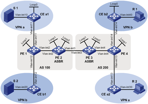
PE interfaces and VPN instances they belong to |
l PE 1: VLAN-interface 11 belongs to VPN instance b; VLAN-interface 12 belongs to VPN instance a; VLAN-interface 2 and Loopback 1 belong to the public network instance. l PE 2: VLAN-interface 2, VLAN-interface 3, Loopback 1 and Loopback 2 belong to the public network instance. l PE 3: VLAN-interface 3, VLAN-interface 4, Loopback 1 and Loopback 2 belong to the public network instance. l PE 4: VLAN-interface 13 belongs to VPN instance a; VLAN-interface 14 belongs to VPN instance b; VLAN-interface 4 and Loopback 1 belong to the public network instance. |
|
Unicast routing protocols and MPLS |
l Configure OSPF separately in AS 100 and AS 200, and configure OSPF between the PEs and CEs. l Establish BGP peer connections between PE 1, PE 2, PE 3 and PE 4 on their respective Loopback 1 interface and exchange all private network routes between them. l Configure MPLS separately in AS 100 and AS 200. |
|
IP multicast routing |
l Enable IP multicast routing in the public instance on PE 1, PE 2, PE 3 and PE 4. l Enable IP multicast routing in VPN instance a on PE 1 and PE 4. l Enable IP multicast routing in VPN instance b on PE 1 and PE 4. l Enable IP multicast routing on CE a1, CE a2, CE b1, and CE b2. |
|
IGMP |
l Run IGMPv2 on VLAN-interface 30 of CE a2. l Run IGMPv2 on VLAN-interface 40 of CE b2. |
|
PIM |
l Enable PIM-SM on all public network interfaces of PE 2 and PE 3. l Enable PIM-SM on all public and private network interfaces of PE 1 and PE 4. l Enable PIM-SM on all interfaces of CE a1, CE a2, CE b1, and CE b2. l Configure Loopback 2 of PE 2 and PE 3 as a C-BSR and a C-RP for their respective AS (to work for all multicast groups). l Configure Loopback 0 of CE a1 as a C-BSR and a C-RP for VPN a (to work for all multicast groups). l Configure Loopback 0 of CE b1 as a C-BSR and a C-RP for VPN b (to work for all multicast groups). |
|
MSDP |
l Establish an MSDP peering relationship between PE 2 and PE 3 on their respective Loopback 1. |
Network diagram
Figure 1-11 Network diagram for multi-AS MD-VPN configuration
|
Device |
Interface |
IP address |
Device |
Interface |
IP address |
|
S 1 |
— |
10.11.5.2/24 |
R 1 |
— |
10.11.8.2/24 |
|
S 2 |
— |
10.11.6.2/24 |
R 2 |
— |
10.11.7.2/24 |
|
PE 1 |
Vlan-int2 |
10.10.1.1/24 |
PE 3 |
Vlan-int4 |
10.10.2.1/24 |
|
|
Vlan-int11 |
10.11.1.1/24 |
|
Vlan-int3 |
192.168.1.2/24 |
|
|
Vlan-int12 |
10.11.2.1/24 |
|
Loop1 |
1.1.1.3/32 |
|
|
Loop1 |
1.1.1.1/32 |
|
Loop2 |
22.22.22.22/32 |
|
PE 2 |
Vlan-int2 |
10.10.1.2/24 |
PE 4 |
Vlan-int4 |
10.10.2.2/24 |
|
|
Vlan-int3 |
192.168.1.1/24 |
|
Vlan-int13 |
10.11.3.1/24 |
|
|
Loop1 |
1.1.1.2/32 |
|
Vlan-int14 |
10.11.4.1/32 |
|
|
Loop2 |
11.11.11.11/32 |
|
Loop2 |
1.1.1.4/32 |
|
CE a1 |
Vlan-int10 |
10.11.5.1/24 |
CE b1 |
Vlan-int20 |
10.11.6.1/24 |
|
|
Vlan-int11 |
10.11.1.2/24 |
|
Vlan-int12 |
10.11.2.2/24 |
|
|
Loop0 |
2.2.2.2/32 |
CE b2 |
Vlan-int40 |
10.11.8.1/24 |
|
CE a2 |
Vlan-int30 |
10.11.7.1/24 |
|
Vlan-int14 |
10.11.4.2/24 |
|
|
Vlan-int13 |
10.11.3.2/24 |
|
Loop0 |
3.3.3.3/32 |
Configuration procedure
1) Configure PE 1
# Configure a Router ID, enable IP multicast routing in the public instance, configure an MPLS LSR ID, and enable the LDP capability.
<PE1> system-view
[PE1] router id 1.1.1.1
[PE1] multicast routing-enable
[PE1] mpls lsr-id 1.1.1.1
[PE1] mpls
[PE1-mpls] quit
[PE1] mpls ldp
[PE1-mpls-ldp] quit
# Create VPN instance a, configure an RD for it, and create an ingress route and an egress route for it; enable IP multicast routing in VPN instance a, configure a share-group address associate an MTI with the VPN instance.
[PE1] ip vpn-instance a
[PE1-vpn-instance-a] route-distinguisher 100:1
[PE1-vpn-instance-a] vpn-target 100:1 export-extcommunity
[PE1-vpn-instance-a] vpn-target 100:1 import-extcommunity
[PE1-vpn-instance-a] multicast routing-enable
[PE1-vpn-instance-a] multicast-domain share-group 239.1.1.1 binding mtunnel 0
[PE1-vpn-instance-a] quit
# Create VPN instance b, configure an RD for it, and create an ingress route and an egress route for it; enable IP multicast routing in VPN instance b, configure a share-group address associate an MTI with the VPN instance.
[PE1] ip vpn-instance b
[PE1-vpn-instance-b] route-distinguisher 200:1
[PE1-vpn-instance-b] vpn-target 200:1 export-extcommunity
[PE1-vpn-instance-b] vpn-target 200:1 import-extcommunity
[PE1-vpn-instance-b] multicast routing-enable
[PE1-vpn-instance-b] multicast-domain share-group 239.4.4.4 binding mtunnel 1
[PE1-vpn-instance-b] quit
# Configure an IP address, and enable PIM-SM and LDP capability on the public network interface VLAN-interface 2.
[PE1] interface vlan-interface 2
[PE1-Vlan-interface2] ip address 10.10.1.1 24
[PE1-Vlan-interface2] pim sm
[PE1-Vlan-interface2] mpls
[PE1-Vlan-interface2] mpls ldp
[PE1-Vlan-interface2] quit
# Bind VLAN-interface 11 to VPN instance a, configure an IP address and enable PIM-SM on the interface.
[PE1] interface vlan-interface 11
[PE1-Vlan-interface11] ip binding vpn-instance a
[PE1-Vlan-interface11] ip address 10.11.1.1 24
[PE1-Vlan-interface11] pim sm
[PE1-Vlan-interface11] quit
# Bind VLAN-interface 12 to VPN instance b, configure an IP address and enable PIM-SM on the interface.
[PE1] interface vlan-interface 12
[PE1-Vlan-interface12] ip binding vpn-instance b
[PE1-Vlan-interface12] ip address 10.11.2.1 24
[PE1-Vlan-interface12] pim sm
[PE1-Vlan-interface12] quit
# Configure an IP address for Loopback 1, and enable PIM-SM.
[PE1] interface loopback 1
[PE1-LoopBack1] ip address 1.1.1.1 32
[PE1-LoopBack1] pim sm
[PE1-LoopBack1] quit
# Configure BGP.
[PE1] bgp 100
[PE1-bgp] group pe1-pe2 internal
[PE1-bgp] peer pe1-pe2 label-route-capability
[PE1-bgp] peer pe1-pe2 connect-interface loopback 1
[PE1-bgp] peer 1.1.1.2 group pe1-pe2
[PE1-bgp] group pe1-pe4 external
[PE1-bgp] peer pe1-pe4 as-number 200
[PE1-bgp] peer pe1-pe4 ebgp-max-hop 255
[PE1-bgp] peer 1.1.1.4 group pe1-pe4
[PE1-bgp] peer 1.1.1.4 connect-interface loopback 1
[PE1–bgp] ipv4-family vpn-instance a
[PE1-bgp-a] import-route ospf 2
[PE1-bgp-a] import-route direct
[PE1-bgp-a] quit
[PE1–bgp] ipv4-family vpn-instance b
[PE1-bgp-b] import-route ospf 3
[PE1-bgp-b] import-route direct
[PE1-bgp-b] quit
[PE1–bgp] ipv4-family vpnv4
[PE1–bgp-af-vpnv4] peer 1.1.1.4 enable
[PE1–bgp-af-vpnv4] quit
[PE1–bgp] quit
With BGP peers configured on PE 1, the interfaces MTI 0 and MTI 1 will automatically obtain IP addresses, which are the loopback interface addresses specified in the BGP peer configuration. The PIM mode running on MTI 0 is the same as on the interfaces in VPN instance a, and the PIM mode running on MTI 1 is the same as on the interfaces in VPN instance b.
# Configure OSPF.
[PE1] ospf 1
[PE1-ospf-1] area 0.0.0.0
[PE1-ospf-1-area-0.0.0.0] network 1.1.1.1 0.0.0.0
[PE1-ospf-1-area-0.0.0.0] network 10.10.0.0 0.0.255.255
[PE1-ospf-1-area-0.0.0.0] quit
[PE1-ospf-1] quit
[PE1] ospf 2 vpn-instance a
[PE1-ospf-2] import-route bgp
[PE1-ospf-2] area 0.0.0.0
[PE1-ospf-2-area-0.0.0.0] network 10.11.0.0 0.0.255.255
[PE1-ospf-2-area-0.0.0.0] quit
[PE1-ospf-2] quit
[PE1] ospf 3 vpn-instance b
[PE1-ospf-3] import-route bgp
[PE1-ospf-3] area 0.0.0.0
[PE1-ospf-3-area-0.0.0.0] network 10.11.0.0 0.0.255.255
[PE1-ospf-3-area-0.0.0.0] quit
[PE1-ospf-3] quit
2) Configure PE 2
# Configure a Router ID, enable IP multicast routing in the public instance, configure an MPLS LSR ID, and enable the LDP capability.
<PE2> system-view
[PE2] router id 1.1.1.2
[PE2] multicast routing-enable
[PE2] mpls lsr-id 1.1.1.2
[PE2] mpls
[PE2-mpls] quit
[PE2] mpls ldp
[PE2-mpls-ldp] quit
# Configure an IP address, and enable PIM-SM and LDP capability on the public network interface VLAN-interface 2.
[PE2] interface vlan-interface 2
[PE2-Vlan-interface2] ip address 10.10.1.2 24
[PE2-Vlan-interface2] pim sm
[PE2-Vlan-interface2] mpls
[PE2-Vlan-interface2] mpls ldp
[PE2-Vlan-interface2] quit
# Configure an IP address, and enable PIM-SM and MPLS capability on the public network interface VLAN-interface 3.
[PE2] interface vlan-interface 3
[PE2-Vlan-interface3] ip address 192.168.1.1 24
[PE2-Vlan-interface3] pim sm
[PE2-Vlan-interface3] mpls
[PE2-Vlan-interface3] quit
# Configure an IP address for Loopback 1, and enable PIM-SM.
[PE2] interface loopback 1
[PE2-LoopBack1] ip address 1.1.1.2 32
[PE2-LoopBack1] pim sm
[PE2-LoopBack1] quit
# Configure an IP address for Loopback 2, and enable PIM-SM.
[PE2] interface loopback 2
[PE2-LoopBack2] ip address 11.11.11.11 32
[PE2-LoopBack2] pim sm
[PE2-LoopBack2] quit
# Configure Loopback 2 as a C-BSR and a C-RP for the public network instance.
[PE2] pim
[PE2-pim] c-bsr loopback 2
[PE2-pim] c-rp loopback 2
[PE2-pim] quit
# Configure a BSR message boundary.
[PE2] interface vlan-interface 3
[PE2-Vlan-interface3] pim bsr-boundary
[PE2-Vlan-interface3] quit
# Establish an MSDP peering relationship.
[PE2] msdp
[PE2-msdp] encap-data-enable
[PE2-msdp] peer 1.1.1.3 connect-interface loopback 1
# Configure a static route.
[PE2] ip route-static 1.1.1.3 32 vlan-interface 3 192.168.1.2
# Configure BGP.
[PE2] bgp 100
[PE2-bgp] import-route ospf 1
[PE2-bgp] group pe2-pe1 internal
[PE2-bgp] peer pe2-pe1 route-policy map2 export
[PE2-bgp] peer pe2-pe1 label-route-capability
[PE2-bgp] peer pe2-pe1 connect-interface loopback 1
[PE2-bgp] peer 1.1.1.1 group pe2-pe1
[PE2-bgp] group pe2-pe3 external
[PE2-bgp] peer pe2-pe3 as-number 200
[PE2-bgp] peer pe2-pe3 ebgp-max-hop 255
[PE2-bgp] peer pe2-pe3 route-policy map1 export
[PE2-bgp] peer pe2-pe3 label-route-capability
[PE2-bgp] peer pe2-pe3 connect-interface loopback 1
[PE2-bgp] peer 1.1.1.3 group pe2-pe3
[PE2–bgp] quit
# Configure OSPF.
[PE2] ospf 1
[PE2-ospf-1] area 0.0.0.0
[PE2-ospf-1-area-0.0.0.0] network 1.1.1.2 0.0.0.0
[PE2-ospf-1-area-0.0.0.0] network 11.11.11.11 0.0.0.0
[PE2-ospf-1-area-0.0.0.0] network 10.10.0.0 0.0.255.255
[PE2-ospf-1-area-0.0.0.0] quit
[PE2-ospf-1] quit
# Configure a route policy.
[PE2] route-policy map1 permit node 10
[PE2-route-policy] apply mpls-label
[PE2-route-policy] quit
[PE2] route-policy map2 permit node 10
[PE2-route-policy] if-match mpls-label
[PE2-route-policy] apply mpls-label
[PE2-route-policy] quit
3) Configure PE 3
# Configure a Router ID, enable IP multicast routing in the public instance, configure an MPLS LSR ID, and enable the LDP capability.
<PE3> system-view
[PE3] router id 1.1.1.3
[PE3] multicast routing-enable
[PE3] mpls lsr-id 1.1.1.3
[PE3] mpls
[PE3-mpls] quit
[PE3] mpls ldp
[PE3-mpls-ldp] quit
# Configure an IP address, and enable PIM-SM and LDP capability on the public network interface VLAN-interface 4.
[PE3] interface vlan-interface 4
[PE3-Vlan-interface4] ip address 10.10.2.1 24
[PE3-Vlan-interface4] pim sm
[PE3-Vlan-interface4] mpls
[PE3-Vlan-interface4] mpls ldp
[PE3-Vlan-interface4] quit
# Configure an IP address, and enable PIM-SM and MPLS capability on the public network interface VLAN-interface 3.
[PE3] interface vlan-interface 3
[PE3-Vlan-interface3] ip address 192.168.1.2 24
[PE3-Vlan-interface3] pim sm
[PE3-Vlan-interface3] mpls
[PE3-Vlan-interface3] quit
# Configure an IP address for Loopback 1, and enable PIM-SM.
[PE3] interface loopback 1
[PE3-LoopBack1] ip address 1.1.1.3 32
[PE3-LoopBack1] pim sm
[PE3-LoopBack1] quit
# Configure an IP address for Loopback 2, and enable PIM-SM.
[PE3] interface loopback 2
[PE3-LoopBack2] ip address 22.22.22.22 32
[PE3-LoopBack2] pim sm
[PE3-LoopBack2] quit
# Configure Loopback 2 as a C-BSR and a C-RP for the public network instance.
[PE3] pim
[PE3-pim] c-bsr loopback 2
[PE3-pim] c-rp loopback 2
[PE3-pim] quit
# Configure a BSR message boundary.
[PE3] interface vlan-interface 3
[PE3-Vlan-interface3] pim bsr-boundary
[PE3-Vlan-interface3] quit
# Establish an MSDP peering relationship.
[PE3] msdp
[PE3-msdp] encap-data-enable
[PE3-msdp] peer 1.1.1.2 connect-interface loopback 1
# Configure a static route.
[PE3] ip route-static 1.1.1.2 32 vlan-interface 3 192.168.1.1
# Configure BGP.
[PE3] bgp 200
[PE3-bgp] import-route ospf 1
[PE3-bgp] group pe3-pe4 internal
[PE3-bgp] peer pe3-pe4 route-policy map2 export
[PE3-bgp] peer pe3-pe4 label-route-capability
[PE3-bgp] peer pe3-pe4 connect-interface loopback 1
[PE3-bgp] peer 1.1.1.4 group pe3-pe4
[PE3-bgp] group pe3-pe4 external
[PE3-bgp] peer pe3-pe4 as-number 100
[PE3-bgp] peer pe3-pe4 ebgp-max-hop 255
[PE3-bgp] peer pe3-pe4 route-policy map1 export
[PE3-bgp] peer pe3-pe4 label-route-capability
[PE3-bgp] peer pe3-pe4 connect-interface loopback 1
[PE3-bgp] peer 1.1.1.2 group pe3-pe4
[PE3–bgp] quit
# Configure OSPF.
[PE3] ospf 1
[PE3-ospf-1] area 0.0.0.0
[PE3-ospf-1-area-0.0.0.0] network 1.1.1.3 0.0.0.0
[PE3-ospf-1-area-0.0.0.0] network 22.22.22.22 0.0.0.0
[PE3-ospf-1-area-0.0.0.0] network 10.10.0.0 0.0.255.255
[PE3-ospf-1-area-0.0.0.0] quit
[PE3-ospf-1] quit
# Configure a route policy.
[PE3] route-policy map1 permit node 10
[PE3-route-policy] apply mpls-label
[PE3-route-policy] quit
[PE3] route-policy map2 permit node 10
[PE3-route-policy] if-match mpls-label
[PE3-route-policy] apply mpls-label
[PE3-route-policy] quit
4) Configure PE 4
# Configure a Router ID, enable IP multicast routing in the public instance, configure an MPLS LSR ID, and enable the LDP capability.
<PE4> system-view
[PE4] router id 1.1.1.4
[PE4] multicast routing-enable
[PE4] mpls lsr-id 1.1.1.4
[PE4] mpls
[PE4-mpls] quit
[PE4] mpls ldp
[PE4-mpls-ldp] quit
# Create VPN instance a, configure an RD for it, and create an ingress route and an egress route for it; enable IP multicast routing in VPN instance a, configure a share-group address associate an MTI with the VPN instance.
[PE4] ip vpn-instance a
[PE4-vpn-instance-a] route-distinguisher 100:1
[PE4-vpn-instance-a] vpn-target 100:1 export-extcommunity
[PE4-vpn-instance-a] vpn-target 100:1 import-extcommunity
[PE4-vpn-instance-a] multicast routing-enable
[PE4-vpn-instance-a] multicast-domain share-group 239.1.1.1 binding mtunnel 0
[PE4-vpn-instance-a] quit
# Create VPN instance b, configure an RD for it, and create an ingress route and an egress route for it; enable IP multicast routing in VPN instance b, configure a share-group address associate an MTI with the VPN instance.
[PE4] ip vpn-instance b
[PE4-vpn-instance-b] route-distinguisher 200:1
[PE4-vpn-instance-b] vpn-target 200:1 export-extcommunity
[PE4-vpn-instance-b] vpn-target 200:1 import-extcommunity
[PE4-vpn-instance-b] multicast routing-enable
[PE4-vpn-instance-b] multicast-domain share-group 239.4.4.4 binding mtunnel 1
[PE4-vpn-instance-b] quit
# Configure an IP address, and enable PIM-SM and LDP capability on the public network interface VLAN-interface 4.
[PE4] interface vlan-interface 4
[PE4-Vlan-interface4] ip address 10.10.2.2 24
[PE4-Vlan-interface4] pim sm
[PE4-Vlan-interface4] mpls
[PE4-Vlan-interface4] mpls ldp
[PE4-Vlan-interface4] quit
# Bind VLAN-interface 13 to VPN instance a, configure an IP address and enable PIM-SM on the interface.
[PE4] interface vlan-interface 13
[PE4-Vlan-interface13] ip binding vpn-instance a
[PE4-Vlan-interface13] ip address 10.11.3.1 24
[PE4-Vlan-interface13] pim sm
[PE4-Vlan-interface13] quit
# Bind VLAN-interface 14 to VPN instance b, configure an IP address and enable PIM-SM on the interface.
[PE4] interface vlan-interface 14
[PE4-Vlan-interface14] ip binding vpn-instance b
[PE4-Vlan-interface14] ip address 10.11.4.1 24
[PE4-Vlan-interface14] pim sm
[PE4-Vlan-interface14] quit
# Configure an IP address for Loopback 1, and enable PIM-SM.
[PE4] interface loopback 1
[PE4-LoopBack1] ip address 1.1.1.4 32
[PE4-LoopBack1] pim sm
[PE4-LoopBack1] quit
# Configure BGP.
[PE4] bgp 100
[PE4-bgp] group pe4-pe3 internal
[PE4-bgp] peer pe4-pe3 label-route-capability
[PE4-bgp] peer pe4-pe3 connect-interface loopback 1
[PE4-bgp] peer 1.1.1.3 group pe4-pe3
[PE4-bgp] group pe4-pe1 external
[PE4-bgp] peer pe4-pe1 as-number 100
[PE4-bgp] peer pe4-pe1 ebgp-max-hop 255
[PE4-bgp] peer 1.1.1.1 group pe4-pe1
[PE4-bgp] peer 1.1.1.1 connect-interface loopback 1
[PE4–bgp] ipv4-family vpn-instance a
[PE4-bgp-a] import-route ospf 2
[PE4-bgp-a] import-route direct
[PE4-bgp-a] quit
[PE4–bgp] ipv4-family vpn-instance b
[PE4-bgp-b] import-route ospf 3
[PE4-bgp-b] import-route direct
[PE4-bgp-b] quit
[PE4–bgp] ipv4-family vpnv4
[PE4–bgp-af-vpnv4] peer 1.1.1.1 enable
[PE4–bgp-af-vpnv4] quit
[PE4–bgp] quit
With BGP peers configured on PE 4, the interfaces MTI 0 and MTI 1 will automatically obtain IP addresses, which are the loopback interface addresses specified in the BGP peer configuration. The PIM mode running on MTI 0 is the same as on the interfaces in VPN instance a, and the PIM mode running on MTI 1 is the same as on the interfaces in VPN instance b.
# Configure OSPF.
[PE4] ospf 1
[PE4-ospf-1] area 0.0.0.0
[PE4-ospf-1-area-0.0.0.0] network 1.1.1.4 0.0.0.0
[PE4-ospf-1-area-0.0.0.0] network 10.10.0.0 0.0.255.255
[PE4-ospf-1-area-0.0.0.0] quit
[PE4-ospf-1] quit
[PE4] ospf 2 vpn-instance a
[PE4-ospf-2] import-route bgp
[PE4-ospf-2] area 0.0.0.0
[PE4-ospf-2-area-0.0.0.0] network 10.11.0.0 0.0.255.255
[PE4-ospf-2-area-0.0.0.0] quit
[PE4-ospf-2] quit
[PE4] ospf 3 vpn-instance b
[PE4-ospf-3] import-route bgp
[PE4-ospf-3] area 0.0.0.0
[PE4-ospf-3-area-0.0.0.0] network 10.11.0.0 0.0.255.255
[PE4-ospf-3-area-0.0.0.0] quit
[PE4-ospf-3] quit
5) Configure CE a1.
# Enable IP multicast routing.
<CEa1> system-view
[CEa1] multicast routing-enable
# Configure an IP address for VLAN-interface 10 and enable PIM-SM on the interface.
[CEa1] interface vlan-interface 10
[CEa1-Vlan-interface10] ip address 10.11.5.1 24
[CEa1-Vlan-interface10] pim sm
[CEa1-Vlan-interface10] quit
# Configure an IP address for VLAN-interface 11 and enable PIM-SM on the interface.
[CEa1] interface vlan-interface 11
[CEa1-Vlan-interface11] ip address 10.11.1.2 24
[CEa1-Vlan-interface11] pim sm
[CEa1-Vlan-interface11] quit
# Configure an IP address for Loopback 1, and enable PIM-SM.
[CEa1] interface loopback 1
[CEa1-LoopBack1] ip address 2.2.2.2 32
[CEa1-LoopBack1] pim sm
[CEa1-LoopBack1] quit
# Configure Loopback 1 as a C-BSR and a C-RP for VPN a.
[CEa1] pim vpn-instance a
[CEa1-pim-a] c-bsr loopback 1
[CEa1-pim-a] c-rp loopback 1
[CEa1-pim-a] quit
# Configure OSPF.
[CEa1] ospf 1
[CEa1-ospf-1] area 0.0.0.0
[CEa1-ospf-1-area-0.0.0.0] network 2.2.2.2 0.0.0.0
[CEa1-ospf-1-area-0.0.0.0] network 10.11.0.0 0.0.255.255
[CEa1-ospf-1-area-0.0.0.0] quit
[CEa1-ospf-1] quit
6) Configure CE b1.
# Enable IP multicast routing.
<CEb1> system-view
[CEb1] multicast routing-enable
# Configure an IP address for VLAN-interface 20 and enable PIM-SM on the interface.
[CEb1] interface vlan-interface 20
[CEb1-Vlan-interface20] ip address 10.11.6.1 24
[CEb1-Vlan-interface20] pim sm
[CEb1-Vlan-interface20] quit
# Configure an IP address for VLAN-interface 12 and enable PIM-SM on the interface.
[CEb1] interface vlan-interface 12
[CEb1-Vlan-interface12] ip address 10.11.2.2 24
[CEb1-Vlan-interface12] pim sm
[CEb1-Vlan-interface12] quit
# Configure OSPF.
[CEb1] ospf 1
[CEb1-ospf-1] area 0.0.0.0
[CEb1-ospf-1-area-0.0.0.0] network 10.11.0.0 0.0.255.255
[CEb1-ospf-1-area-0.0.0.0] quit
[CEb1-ospf-1] quit
7) Configure CE a2.
# Enable IP multicast routing.
<CEa2> system-view
[CEa2] multicast routing-enable
# Configure an IP address for VLAN-interface 30 and enable IGMP and PIM-SM on the interface.
[CEa2] interface vlan-interface 30
[CEa2-Vlan-interface30] ip address 10.11.7.1 24
[CEa2-Vlan-interface30] igmp enable
[CEa2-Vlan-interface30] pim sm
[CEa2-Vlan-interface30] quit
# Configure an IP address for VLAN-interface 13 and enable PIM-SM on the interface.
[CEa2] interface vlan-interface 13
[CEa2-Vlan-interface13] ip address 10.11.3.2 24
[CEa2-Vlan-interface13] pim sm
[CEa2-Vlan-interface13] quit
# Configure OSPF.
[CEa2] ospf 1
[CEa2-ospf-1] area 0.0.0.0
[CEa2-ospf-1-area-0.0.0.0] network 10.11.0.0 0.0.255.255
[CEa2-ospf-1-area-0.0.0.0] quit
[CEa2-ospf-1] quit
8) Configure CE b2.
# Enable IP multicast routing.
<CEb2> system-view
[CEb2] multicast routing-enable
# Configure an IP address for VLAN-interface 40 and enable IGMP and PIM-SM on the interface.
[CEb2] interface vlan-interface 40
[CEb2-Vlan-interface40] ip address 10.11.8.1 24
[CEb2-Vlan-interface40] igmp enable
[CEb2-Vlan-interface40] pim sm
[CEb2-Vlan-interface40] quit
# Configure an IP address for VLAN-interface 14 and enable PIM-SM on the interface.
[CEb2] interface vlan-interface 14
[CEb2-Vlan-interface14] ip address 10.11.4.2 24
[CEb2-Vlan-interface14] pim sm
[CEb2-Vlan-interface14] quit
# Configure an IP address for Loopback 1, and enable PIM-SM.
[CEb2] interface loopback 1
[CEb2-LoopBack1] ip address 3.3.3.3 32
[CEb2-LoopBack1] pim sm
[CEb2-LoopBack1] quit
# Configure Loopback 1 as a C-BSR and a C-RP for VPN b.
[CEb2] pim vpn-instance b
[CEb2-pim-b] c-bsr loopback 1
[CEb2-pim-b] c-rp loopback 1
[CEb2-pim-b] quit
# Configure OSPF.
[CEb2] ospf 1
[CEb2-ospf-1] area 0.0.0.0
[CEb2-ospf-1-area-0.0.0.0] network 3.3.3.3 0.0.0.0
[CEb2-ospf-1-area-0.0.0.0] network 10.11.0.0 0.0.255.255
[CEb2-ospf-1-area-0.0.0.0] quit
[CEb2-ospf-1] quit
9) Verify the configuration
To view the share-group information of a VPN instance, use the display multicast-domain vpn-instance share-group command.
# View the share-group information of VPN instance a on PE 1.
<PE1> display multicast-domain vpn-instance a share-group
MD local share-group information for VPN-Instance: a
Share-group: 239.1.1.1
MTunnel address: 1.1.1.1
# View the share-group information of VPN instance b on PE 1.
<PE1> display multicast-domain vpn-instance b share-group
MD local share-group information for VPN-Instance: b
Share-group: 239.4.4.4
MTunnel address: 1.1.1.1
# View the share-group information of VPN instance a on PE 4.
<PE4> display multicast-domain vpn-instance a share-group
MD local share-group information for VPN-Instance: a
Share-group: 239.1.1.1
MTunnel address: 1.1.1.4
# View the share-group information of VPN instance b on PE 4.
<PE4> display multicast-domain vpn-instance b share-group
MD local share-group information for VPN-Instance: b
Share-group: 239.4.4.4
MTunnel address: 1.1.1.4
Troubleshooting MD-VPN Configuration
Unable to Establish a Share-MDT
Symptom
A share-MDT cannot be established. PIM adjacencies cannot be established between the same VPN instance’s interfaces on different PE devices.
Analysis
l On different PE devices, the same share-group must be configured for the same VPN instance. A share-group address uniquely identifies a share-MDT. If different share-group addresses have been configured for a VPN instance on different PE devices, a share-MDT cannot be established for that VPN instance on different PE devices.
l The same PIM mode must run on all the interfaces of the same VPN instance on different PE devices and on all the interfaces of the P router; otherwise, a share-MDT cannot be correctly built for the VPN instance and PIM adjacencies cannot be established between the VPN instance on the local PE device and the same VPN instance on the remote PE device.
l BGP and unicast route configurations are prerequisites for the MTI interface to obtain an IP address automatically, and PIM is enabled on at least one interface of the VPN instance so that PIM can be enabled on the MTI interface. PIM adjacencies can be established between the same VPN instance on different PE devices only after the MTI interface obtains an IP address and gets PIM enabled.
Solution
1) Check the share-group address: Use the display multicast-domain vpn-instance share-group command to verify that the same share-group address has been configured for the same VPN instance on different PE devices.
2) Check the running PIM mode: Use the display pim interface command to verify that PIM is enabled on at least one interface of the same VPN on different PE devices and the same PIM mode is running on all the interfaces of the same VPN instance on different PE devices and on all the interfaces of the P router.
3) Check unicast routes. Use the display ip routing-table command to verify that a unicast route exists from the VPN instance on the local PE device to the same VPN instance on each remote PE device.
4) Check BGP peer configuration: Use the display bgp peer command to verify that the BGP peer connections have been correctly configured.
Unable to Build an MVRF
Symptom
A VPN instance cannot create an MVRF correctly.
Analysis
l If PIM-SM is running in the VPN instance, the BSR information for the VPN instance is required; otherwise, the VPN instance’s MVRF cannot be correctly established.
l If PIM-SM is running in the VPN instance, the RP information for the VPN instance is required. If a unicast route to the RP is not available, this means that a PIM adjacency has not been correctly established between the public instance and the VPN instance, and thus VPN instance cannot correctly establish its MVRF.
l The customer DR must have a route to the private network RP.
Solution
1) Use the display pim bsr-info command to check whether the BSR information exists in the public instance and VPN instance. If not, check whether a unicast route exists to the BSR.
2) Use the display pim rp-info command to view the RP information. If no RP information is available, check whether a unicast route exists to the RP. Use the display pim neighbor command to check whether the PIM adjacencies have correctly established in the public network and the private network.
3) Use the ping command to check the connectivity between the private network DR and the private network RP.
