- Table of Contents
-
- 02-IP Services Volume
- 00-IP Services Volume Organization
- 01-IP Addressing Configuration
- 02-ARP Configuration.doc
- 03-DHCP Configuration.doc
- 04-DNS Configuration
- 05-IP Performance Configuration
- 06-UDP Helper Configuration
- 07-URPF Configuration
- 08-IPv6 Basics Configuration
- 09-Dual Stack Configuration
- 10-Tunneling Configuration
- 11-sFlow Configuration
- Related Documents
-
| Title | Size | Download |
|---|---|---|
| 02-ARP Configuration.doc | 268.46 KB |
ARP Address Resolution Process
Configuring a Static ARP Entry
Configuring the Maximum Number of ARP Entries for a VLAN Interface
Setting the Aging Time for Dynamic ARP Entries
Enabling the Support for ARP Requests from a Natural Network
Introduction to Gratuitous ARP
Displaying and Maintaining ARP
Displaying and Maintaining Proxy ARP
Proxy ARP Configuration Examples
Proxy ARP Configuration Example
Local Proxy ARP Configuration Example in Case of Port Isolation
Local Proxy ARP Configuration Example in Super VLAN
Local Proxy ARP Configuration Example in Isolate-user-vlan
3 ARP Attack Defense Configuration
Configuring ARP Source Suppression
Introduction to ARP Source Suppression
Configuring ARP Source Suppression
Displaying and Maintaining ARP Source Suppression
Configuring ARP Defense Against IP Packet Attack
Introduction to ARP Defense Against IP Packet Attack
Enabling ARP Defense Against IP Packet Attack
Enabling ARP Detection Based on DHCP Snooping Security Entries
Configuring ARP Detection Based on Specified Objects
Configuring ARP Packet Rate Limit
Displaying and Maintaining ARP Detection
ARP Detection Configuration Example
When configuring ARP, go to these sections for information you are interested in:
l Displaying and Maintaining ARP
ARP Overview
ARP Function
The Address Resolution Protocol (ARP) is used to resolve an IP address into an Ethernet MAC address (or physical address).
In a LAN, when a device is to send data to another device, the sending device must know the network layer address (that is, the IP address) of the destination device. Because IP datagrams must be encapsulated within Ethernet frames before they can be transmitted over physical networks, the sending device also needs to know the physical address of the destination device. Therefore, a mapping between the IP address and the physical address is needed. ARP is the protocol to implement the mapping function.
ARP Message Format
ARP messages are classified into ARP requests and ARP replies. Figure 1-1 shows the format of the ARP request/reply.
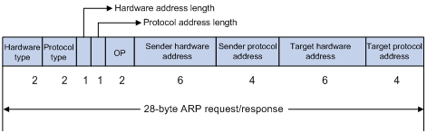
The following explains the fields in Figure 1-1.
l Hardware type: This field specifies the hardware address type. The value “1” represents Ethernet.
l Protocol type: This field specifies the type of the protocol address to be mapped. The hexadecimal value “0x0800” represents IP.
l Hardware address length and protocol address length: They respectively specify the length of a hardware address and a protocol address, in bytes. For an Ethernet address, the value of the hardware address length field is "6”. For an IP(v4) address, the value of the protocol address length field is “4”.
l OP: Operation code. This field specifies the type of ARP message. The value “1” represents an ARP request and “2” represents an ARP reply.
l Sender hardware address: This field specifies the hardware address of the device sending the message.
l Sender protocol address: This field specifies the protocol address of the device sending the message.
l Target hardware address: This field specifies the hardware address of the device the message is being sent to.
l Target protocol address: This field specifies the protocol address of the device the message is being sent to.
ARP Address Resolution Process
Suppose that Host A and Host B are on the same subnet and Host A sends a packet to Host B, as shown in Figure 1-2. The resolution process is as follows:
1) Host A looks in its ARP table to see whether there is an ARP entry for Host B. If yes, Host A uses the MAC address in the entry to encapsulate the IP packet into a data link layer frame and sends the frame to Host B.
2) If Host A finds no entry for Host B, Host A buffers the packet and broadcasts an ARP request, in which the source IP address and source MAC address are respectively the IP address and MAC address of Host A and the destination IP address and MAC address are respectively the IP address of Host B and an all-zero MAC address. Because the ARP request is broadcast, all hosts on this subnet can receive the request, but only the requested host (namely, Host B) will process the request.
3) Host B compares its own IP address with the destination IP address in the ARP request. If they are the same, Host B saves the source IP address and source MAC address into its ARP table, encapsulates its MAC address into an ARP reply, and unicasts the reply to Host A.
4) After receiving the ARP reply, Host A adds the MAC address of Host B into its ARP table. Meanwhile, Host A encapsulates the IP packet and sends it out.
Figure 1-2 ARP address resolution process

If Host A and Host B are not on the same subnet, Host A first sends an ARP request to the gateway. The destination IP address in the ARP request is the IP address of the gateway. After obtaining the MAC address of the gateway from an ARP reply, Host A sends the packet to the gateway. If the gateway maintains the ARP entry of Host B, it forwards the packet to Host B directly; if not, it broadcasts an ARP request, in which the target IP address is the IP address of Host B. After obtaining the MAC address of Host B, the gateway sends the packet to Host B.
ARP Table
After obtaining the destination MAC address, the device adds the IP-to-MAC mapping into its own ARP table. This mapping is used for forwarding packets with the same destination in future.
An ARP table contains ARP entries, which fall into two categories: dynamic and static.
Dynamic ARP entry
A dynamic entry is automatically created and maintained by ARP. It can get aged, be updated by a new ARP packet, or be overwritten by a static ARP entry. When the aging timer expires or the port goes down, the corresponding dynamic ARP entry will be removed.
Static ARP entry
A static ARP entry is manually configured and maintained. It cannot get aged or be overwritten by a dynamic ARP entry.
Using static ARP entries enhances communication security. After a static ARP entry is specified, only a specific MAC address is associated with the specified IP address. Attack packets cannot modify the IP-to-MAC mapping. Thus, communications between devices are protected.
Static ARP entries can be classified into permanent or non-permanent.
l A permanent static ARP entry can be directly used to forward packets. When configuring a permanent static ARP entry, you must configure a VLAN and outbound port for the entry besides the IP address and MAC address.
l A non-permanent static ARP entry cannot be directly used for forwarding data. When configuring a non-permanent static ARP entry, you only need to configure the IP address and MAC address. When forwarding IP packets, the device sends an ARP request. If the source IP and MAC addresses in the received ARP reply are the same as the configured IP and MAC addresses, the device adds the port receiving the ARP reply into the static ARP entry. Now the entry can be used for forwarding IP packets.
![]()
l Usually ARP dynamically resolves IP addresses to MAC addresses, without manual intervention.
l To allow communication with a device using a fixed IP-to-MAC mapping, configure a short static ARP entry for it. To allow communication with a device through a specific interface in a specific VLAN and using a fixed IP-to-MAC mapping, configure a long static ARP entry for it.
Configuring ARP
Configuring a Static ARP Entry
A static ARP entry is effective when the device works normally. However, when a VLAN or VLAN interface to which a static ARP entry corresponds is deleted, the entry, if permanent, will be deleted, and if non-permanent and resolved, will become unresolved.
Follow these steps to configure a static ARP entry:
|
To do… |
Use the command… |
Remarks |
|
Enter system view |
system-view |
— |
|
Configure a permanent static ARP entry |
arp static ip-address mac-address vlan-id interface-type interface-number [ vpn-instance vpn-instance-name ] |
Required No permanent static ARP entry is configured by default. |
|
Configure a non-permanent static ARP entry |
arp static ip-address mac-address [ vpn-instance vpn-instance-name ] |
Required No non-permanent static ARP entry is configured by default. |
![]()
l The vlan-id argument must be the ID of an existing VLAN which corresponds to the ARP entries. In addition, the Ethernet interface following the argument must belong to that VLAN. A VLAN interface must be created for the VLAN.
l The IP address of the VLAN interface corresponding to the vlan-id argument must belong to the same network segment as the IP address specified by the ip-address argument.
Configuring the Maximum Number of ARP Entries for a VLAN Interface
Follow these steps to set the maximum number of dynamic ARP entries that a VLAN interface can learn:
|
To do… |
Use the command… |
Remarks |
|
Enter system view |
system-view |
— |
|
Enter VLAN interface view |
interface Vlan-interface vlan-id |
— |
|
Set the maximum number of dynamic ARP entries that a VLAN interface can learn |
arp max-learning-num number |
Optional 8192 by default. |
Setting the Aging Time for Dynamic ARP Entries
To keep pace with the network changes, the ARP table is refreshed. Each dynamic ARP entry in the ARP table has a limited lifetime rather than is always valid. Dynamic ARP entries that are not refreshed before expiration are deleted from the ARP table. The lifetime is called the aging time. The aging time is reset each time the dynamic ARP entry is used within the lifetime. You can adjust the aging time for dynamic ARP entries according to the actual network condition.
Follow these steps to set aging time for dynamic ARP entries:
|
To do… |
Use the command… |
Remarks |
|
Enter system view |
system-view |
— |
|
Set aging time for dynamic ARP entries |
arp timer aging aging-time |
Optional 20 minutes by default. |
Enabling the ARP Entry Check
The ARP entry check function disables the device from learning multicast MAC addresses. With the ARP entry check enabled, the device cannot learn any ARP entry with a multicast MAC address, and configuring such a static ARP entry is not allowed; otherwise, the system displays error messages.
After the ARP entry check is disabled, the device can learn the ARP entry with a multicast MAC address, and you can also configure such a static ARP entry on the device.
Follow these steps to enable the ARP entry check:
|
To do… |
Use the command… |
Remarks |
|
Enter system view |
system-view |
— |
|
Enable the ARP entry check |
arp check enable |
Optional Enabled by default. |
Currently, enabling ARP entry check on an S7500E series Ethernet switch will disallow configuration of static ARP entries with multicast MAC addresses; dynamic ARP entries with multicast MAC addresses can never be learned.
Enabling the Support for ARP Requests from a Natural Network
When learning MAC addresses, if the device finds that the source IP address of an ARP packet and the IP address of the inbound interface are not on the same subnet, the device will further judge whether these two IP addresses are on the same natural network.
Suppose that the IP address of VLAN-interface 10 is 10.10.10.5/24 and that this interface receives an ARP packet from 10.11.11.1/8. Because these two IP addresses are not on the same subnet, VLAN-interface 10 cannot process the packet. With this feature enabled, the device will make a judgment on natural network basis. Because the IP address of VLAN-interface 10 is a Class A address and its default mask length is 8, these two IP addresses are on the same natural network. In this way, VLAN-interface 10 can learn the MAC address of the source IP address 10.11.11.1.
Follow these steps to enable the support for ARP requests from a natural network:
|
To do… |
Use the command… |
Remarks |
|
Enter system view |
system-view |
— |
|
Enable the support for ARP requests from a natural network |
naturemask-arp enable |
Required Disabled by default. |
ARP Configuration Example
Network requirements
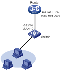
As shown in Figure 1-3, hosts are connected to Switch, which is connected to Router through interface GigabitEthernet 2/0/1 belonging to VLAN 10. The IP address of Router is 192.168.1.1/24. The MAC address of Router is 00e0-fc01-0000.
To enhance security of communications between each host and Switch, static ARP entries are configured on Switch.
Figure 1-3 Network diagram for configuring static ARP entries
Configuration procedure
Configure Switch
# Create VLAN 10.
<Switch> system-view
[Switch] vlan 10
[Switch-vlan10] quit
# Add interfcace GigabitEthernet2/0/1 to VLAN 10.
[Switch] interface GigabitEthernet2/0/1
[Switch-GigabitEthernet2/0/1] port access vlan 10
[Switch-GigabitEthernet2/0/1] quit
# Create interface VLAN-interace 10 and configure its IP address.
[Switch] interface vlan-interface 10
[Switch-vlan-interface10] ip address 192.168.1.2 8
[Switch-vlan-interface10] quit
# Configure a static ARP entry with IP address 192.168.1.1 and MAC address 00e0-fc01-0000. The outgoing interface corresponding to the static ARP entry is GigabitEthernet2/0/1 belonging to VLAN 10.
[Switch] arp static 192.168.1.1 00e0-fc01-0000 10 GigabitEthernet2/0/1
# View information about static ARP entries.
[Switch] display arp static
Type: S-Static D-Dynamic
IP Address MAC Address VLAN ID Interface Aging Type
192.168.1.1 00e0-fc01-0000 10 GE2/0/1 N/A S
Configuring Gratuitous ARP
Introduction to Gratuitous ARP
A gratuitous ARP packet is a special ARP packet, in which the source IP address and destination IP address are both the IP address of the sender, the source MAC address is the MAC address of the sender, and the destination MAC address is a broadcast address.
A device can implement the following functions by sending gratuitous ARP packets:
l Determining whether its IP address is already used by another device.
l Informing other devices of its MAC address change so that they can update their ARP entries.
A device receiving a gratuitous ARP packet can add the information carried in the packet to its own dynamic ARP table if it finds no corresponding ARP entry for the ARP packet in the cache.
Configuring Gratuitous ARP
Follow these steps to configure gratuitous ARP:
|
Use the command… |
Remarks |
|
|
Enter system view |
system-view |
— |
|
Enable the device to send gratuitous ARP packets when receiving ARP requests from another network segment |
gratuitous-arp-sending enable |
Required By default, a device cannot send gratuitous ARP packets when receiving ARP requests from another network segment. |
|
Enable the gratuitous ARP packet learning function |
gratuitous-arp-learning enable |
Optional Enabled by default. |
Displaying and Maintaining ARP
|
To do… |
Use the command… |
Remarks |
|
Display the ARP entries in the ARP mapping table |
display arp [ [ all | dynamic | static ] [ slot slot-id ] | vlan vlan-id | interface interface-type interface-number ] [ [ verbose ] [ | { begin | exclude | include } string ] | count ] |
Available in any view |
|
Display the ARP entries for a specified IP address |
display arp ip-address [ slot slot-id ] [ verbose ] [ | { begin | exclude | include } string ] |
Available in any view |
|
Display the aging time for dynamic ARP entries |
display arp timer aging |
Available in any view |
|
Display the configuration information of ARP source suppression |
display arp source-suppression |
Available in any view |
|
Display the ARP entries for a specified VPN instance |
display arp vpn-instance vpn-instance-name [ | { begin | exclude | include } string | count ] |
Available in any view |
|
Clear ARP entries from the ARP mapping table |
reset arp { all | dynamic | static | slot slot-id | interface interface-type interface-number } |
Available in user view |
![]()
Executing the reset arp slot slot-id or the reset arp interface interface-type interface-number command only removes dynamic ARP entries of the specified slot or port. To remove specified static ARP entries, you need to use the undo arp ip-address command.
When configuring proxy ARP, go to these sections for information you are interested in:
l Displaying and Maintaining Proxy ARP
Proxy ARP Overview
If a host sends an ARP request for the MAC address of another host that resides in another subnet or is isolated from the sending host at layer 2, the device in between must be able to respond to the request to allow Layer 3 communication between the two hosts (in this case, the sending host considers the requested host is on the same subnet). This is achieved by proxy ARP.
Proxy ARP involves proxy ARP and local proxy ARP.
In one of the following cases, you need to enable local proxy ARP:
l Hosts connected to different isolated layer 2 ports in the same VLAN need to communicate at Layer 3.
l If a super VLAN is configured, hosts in different sub VLANs of the super VLAN need to communicate at Layer 3.
l If an isolate-user-vlan is configured, devices in different secondary VLANs of the isolate-user-vlan need to communicate at layer 3.
Enabling Proxy ARP
Follow these steps to enable proxy ARP in VLAN interface view/Ethernet interface view or enable local proxy ARP in VLAN interface view:
|
To do… |
Use the command… |
Remarks |
|
Enter system view |
system-view |
— |
|
Enter VLAN interface view |
interface Vlan-interface vlan-id |
Required |
|
Enable proxy ARP |
proxy-arp enable |
Required Disabled by default. |
|
Enable local proxy ARP |
local-proxy-arp enable |
Required Disabled by default. |
Displaying and Maintaining Proxy ARP
|
To do… |
Use the command… |
Remarks |
|
Display whether proxy ARP is enabled |
display proxy-arp [ interface Vlan-interface vlan-id ] |
Available in any view |
|
Display whether local proxy ARP is enabled |
display local-proxy-arp [ interface Vlan-interface vlan-id ] |
Available in any view |
Proxy ARP Configuration Examples
Proxy ARP Configuration Example
Network requirements
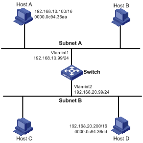
Host A and Host D have IP addresses of the same network segment. Host A belongs to VLAN 1, and Host D belongs to VLAN 2. Configure proxy ARP on the device to enable the communication between the two hosts.
Network diagram
Figure 2-1 Network diagram for proxy ARP
Configuration procedure
# Configure Proxy ARP on the device to enable the communication between Host A and Host D.
<Switch> system-view
[Switch] interface vlan-interface 1
[Switch-Vlan-interface1] ip address 192.168.10.99 255.255.255.0
[Switch-Vlan-interface1] proxy-arp enable
[Switch-Vlan-interface1] quit
[Switch] vlan 2
[Switch-vlan2] quit
[Switch] interface vlan-interface 2
[Switch-Vlan-interface2] ip address 192.168.20.99 255.255.255.0
[Switch-Vlan-interface2] proxy-arp enable
[Switch-Vlan-interface2] quit
Local Proxy ARP Configuration Example in Case of Port Isolation
Network requirements
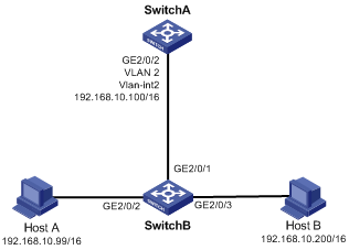
l Host A and Host B belong to the same VLAN, and are connected to GigabitEthernet 2/0/2 and GigabitEthernet 2/0/3 of Switch B respectively.
l Switch B is connected to Switch A via GigabitEthernet 2/0/1.
l On Switch B, port isolation are configured on GigabitEthernet 2/0/2 and GigabitEthernet 2/0/3. Enable local proxy ARP on Switch A to allow communication between Host A and Host B.
Network diagram
Figure 2-2 Network diagram for local proxy ARP between isolated ports
Configuration procedure
1) Configure Switch B
# Create VLAN 2 on Switch B, on which GigabitEthernet 2/0/1, GigabitEthernet 2/0/2 and GigabitEthernet 2/0/3 belong to VLAN 2. Host A and Host B are isolated and unable to exchange Layer 2 packets.
<SwitchB> system-view
[SwitchB] vlan 2
[SwitchB-vlan2] port gigabitethernet 2/0/1
[SwitchB-vlan2] port gigabitethernet 2/0/2
[SwitchB-vlan2] port gigabitethernet 2/0/3
[SwitchB-vlan2] quit
[SwitchB] interface gigabitethernet 2/0/2
[SwitchB-GigabitEthernet2/0/2] port-isolate enable
[SwitchB-GigabitEthernet2/0/2] quit
[SwitchB] interface gigabitethernet 2/0/3
[SwitchB-GigabitEthernet2/0/3] port-isolate enable
[SwitchB-GigabitEthernet2/0/3] quit
2) Configure Switch A
# Configure an IP address of VLAN-interface 2.
[SwitchA] vlan 2
[SwitchA-vlan2] port gigabitethernet 2/0/2
[SwitchA-vlan2] quit
[SwitchA] interface vlan-interface 2
[SwitchA-Vlan-interface2] ip address 192.168.10.100 255.255.0.0
Ping Host B on Host A to verify that the two hosts cannot be pinged through, which indicates they are isolated at Layer 2.
# Configure local proxy ARP to let Host A and Host B communicate at Layer 3.
[SwitchA-Vlan-interface2] local-proxy-arp enable
[SwitchA-Vlan-interface2] quit
Ping Host B on Host A to verify that the two hosts can be pinged through, which indicates Layer 3 communication is implemented.
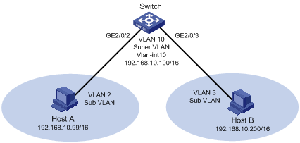
Local Proxy ARP Configuration Example in Super VLAN
Network requirements
l A super VLAN, VLAN 10, is created, with the interface IP address being 192.168.10.100/16.
l Sub-VLANs (VLAN 2 and VLAN 3) are created.
l GigabitEthernet2/0/2 belongs to VLAN 2 and GigabitEthernet2/0/3 belongs to VLAN 3.
l Layer 3 communication is implemented between the sub-VLANs.
Network diagram
Figure 2-3 Network diagram for local proxy ARP in super VLAN
Configuration Procedure
# Create the super VLAN and the sub-VLANs. Add GigabitEthernet 2/0/2 1/2 to VLAN 2 and GigabitEthernet 2/0/3 to VLAN 3. Configure the IP address 192.168.10.100/16 for the interface of VLAN 10.
[Switch] vlan 2
[Switch-vlan2] port gigabitethernet 2/0/2
[Switch-vlan2] quit
[Switch] vlan 3
[Switch-vlan3] port gigabitethernet 2/0/3
[Switch-vlan3] quit
[Switch] vlan 10
[Switch-vlan10] supervlan
[Switch-vlan10] interface vlan-interface 10
[Switch-Vlan-interface10] ip address 192.168.10.100 255.255.0.0
[Switch-Vlan-interface10] quit
Ping Host B on Host A to verify that the two hosts are not reachable to each other, which indicates they are isolated at Layer 2.
# Configure the local proxy ARP to implement Layer 3 communication between sub-VLANs.
<Switch> system-view
[Switch] interface vlan-interface 10
[Switch-Vlan-interface10] local-proxy-arp enable
[Switch-Vlan-interface10] quit
Ping Host B on Host A to verify that the two hosts are reachable to each other, which indicates Layer 3 communication is implemented.
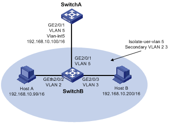
Local Proxy ARP Configuration Example in Isolate-user-vlan
Network requirements
l Switch A is attached to Switch B through GigabitEthernet 2/0/1.
l VLAN 5 on Switch B is an isolate-user-vlan, which includes uplink port GigabitEthernet 2/0/1 and two secondary VLANs (VLAN 2 and VLAN 3). GigabitEthernet 2/0/2 belongs to VLAN 2, and GigabitEthernet 2/0/3 belongs to VLAN 3.
l Configure local proxy ARP on Switch A to implement Layer 3 communication between VLAN 2 and VLAN 3.
Network diagram
Figure 2-4 Network diagram for local proxy ARP configuration in isolate-user-vlan
Configuration procedure
1) Configure the Switch B
<SwitchB> system-view
[SwitchB] vlan 2
[SwitchB-vlan2] port gigabitethernet 2/0/2
[SwitchB-vlan2] quit
[SwitchB] vlan 3
[SwitchB-vlan3] port gigabitethernet 2/0/3
[SwitchB-vlan3] quit
[SwitchB] vlan 5
[SwitchB-vlan5] port gigabitethernet 2/0/1
[SwitchB-vlan5] isolate-user-vlan enable
[SwitchB-vlan5] quit
[SwitchB] isolate-user-vlan 5 secondary 2 3
2) Configure Switch A
# Create VLAN 5 and add GigabitEthernet2/0/1 to it.
<SwitchA> system-view
[SwitchA] vlan 5
[SwitchA-vlan5] port gigabitethernet 2/0/1
[SwitchA-vlan5] interface vlan-interface 5
[SwitchA-Vlan-interface5] ip address 192.168.10.100 255.255.0.0
Ping Host B on Host A to verify that the two hosts are not reachable to each other, which indicates they are isolated at Layer 2.
# Configure local proxy ARP to implement communication between VLAN 2 and VLAN 3.
[SwitchA-Vlan-interface5] local-proxy-arp enable
[SwitchA-Vlan-interface5] quit
Ping Host B on Host A to verify that the two hosts are reachable to each other, which indicates Layer 3 communication is implemented.
When configuring ARP attack defense, go to these sections for information you are interested in:
l Configuring ARP Source Suppression
l Configuring ARP Defense Against IP Packet Attack
Configuring ARP Source Suppression
Introduction to ARP Source Suppression
If a device receives large numbers of IP packets from a host to unreachable destinations,
l The device sends large numbers of ARP requests to the destination subnets, which increases the load of the destination subnets.
l The device continuously resolves destination IP addresses, which increase the load of the CPU.
To protect the device from such attacks, you can enable the ARP source suppression function. With the function enabled, whenever the number of packets with unresolvable destination IP addresses from a host within five seconds exceeds a specified threshold, the device suppress the sending host from triggering any ARP requests within the following five seconds.
Configuring ARP Source Suppression
Follow these steps to configure ARP source suppression:
|
To do… |
Use the command… |
Remarks |
|
Enter system view |
system-view |
— |
|
Enable ARP source suppression |
arp source-suppression enable |
Required Disabled by default. |
|
Set the maximum number of packets with the same source IP address but unresolvable destination IP addresses that the device can receive in five consecutive seconds |
arp source-suppression limit limit-value |
Optional 10 by default. |
Displaying and Maintaining ARP Source Suppression
|
To do… |
Use the command… |
Remarks |
|
Display the ARP source suppression configuration information |
display arp source-suppression |
Available in any view |
Configuring ARP Defense Against IP Packet Attack
Introduction to ARP Defense Against IP Packet Attack
When forwarding an IP packet, a device depends on ARP to resolve the MAC address of the next hop. If the address resolution is successful, the forwarding chip forwards the packet directly. Otherwise, the device runs software for further processing. If the device cannot resolve the next hops for large numbers of incoming packets, the CPU of the device will be exhausted. This is called IP packet attacks.
To protect a device against IP packet attacks, you can enable the ARP defense against IP packet attack function. After receiving an IP packet whose next hop cannot be resolved by ARP, a device with this function enabled creates a black hole route immediately and the forwarding chip simply drops all packets matching the next hop during the age time of the black hole route.
Enabling ARP Defense Against IP Packet Attack
The ARP defense against IP packet attack function applies to packets to be forwarded and those originated by the device.
Follow these steps to configure ARP defense against IP packet attack:
|
To do… |
Use the command… |
Remarks |
|
Enter system view |
system-view |
— |
|
Enable ARP defense against IP packet attack |
arp resolving-route enable |
Optional Enabled by default. |
Configuring ARP Detection
Introduction to ARP Detection
In normal cases, a Layer 2 access device broadcasts an ARP request within a VLAN, and forwards ARP responses at Layer 2. If an attacker sends an ARP request with the source being the IP address of another client, the corresponding ARP entry maintained by the gateway or other clients is modified. Consequently, the attacker will receive the packets sent to the client.
The ARP detection feature allows only the ARP packets of legal clients to be forwarded.
Enabling ARP Detection Based on DHCP Snooping Security Entries
With this feature enabled, the device matches the source IP and MAC addresses of an ARP packet received from the VLAN to the DHCP snooping security entries. If a match is found, the packet is forwarded; if not, it is discarded.
You can set a port in the VLAN as trusted or untrusted. ARP packets received on a trusted port will be forwarded directly, while ARP packets received on an untrusted port will be checked.
Before performing this configuration, make sure DHCP snooping is enabled. Refer to DHCP Configuration in the IP Services Volume for how to enable DHCP snooping.
Follow these steps to enable ARP detection for a VLAN and specify a trusted port:
|
To do… |
Use the command… |
Remarks |
|
Enter system view |
system-view |
— |
|
Enter VLAN view |
vlan vlan-id |
— |
|
Enable ARP detection |
arp detection enable |
Required Disabled by default. That is, the ARP packets received on all the ports in the VLAN will not be checked. |
|
Return to system view |
quit |
— |
|
Enter Ethernet port view |
interface interface-type interface-number |
— |
|
Configure the port as a trusted port |
arp detection trust |
Optional The port is an untrusted port by default. |
Configuring ARP Detection Based on Specified Objects
You can also specify objects in ARP packets to be detected. The objects involve:
l src-mac: Checks whether the sender MAC address of an ARP packet is identical to the source MAC address in the Ethernet header. If they are identical, the packet is forwarded; otherwise, the packet is discarded.
l dst-mac: Checks the target MAC address of ARP responses. If the target MAC address is all-zero, all-F, or inconsistent with the destination MAC address in the Ethernet header, the packet is considered invalid and discarded.
l ip: Checks both the source and destination IP addresses in an ARP packet. The all-zero, all-F or multicast IP addresses are considered invalid and the corresponding packets are discarded. With this object specified, the source IP address of both ARP requests and responses will be checked, and destination IP address of ARP responses will be checked.
Before performing the following configuration, make sure you have configured the arp detection enable command.
Follow these steps to configure ARP detection based on specified objects:
|
To do… |
Use the command… |
Remarks |
|
Enter system view |
system-view |
— |
|
Specify objects for ARP detection |
arp detection validate { dst-mac | ip | src-mac } * |
Required By default, the checking of the MAC addresses and IP addresses of ARP packets is disabled. |
![]()
If both the ARP detection based on specified objects and the ARP detection based on snooping security entries are enabled, the former one applies first, and then the latter applies.
Configuring ARP Packet Rate Limit
ARP packets that pass ARP detection are delivered to the CPU. This feature allows you to limit the rate of ARP packets to be sent to the CPU.
Before performing the following configuration, make sure you have configured the arp detection enable command.
Follow these steps to configure ARP packet rate limit:
|
To do… |
Use the command… |
Remarks |
|
Enter system view |
system-view |
— |
|
Enter Ethernet port view |
interface interface-type interface-number |
— |
|
Configure ARP packet rate limit |
arp rate-limit { disable | rate pps drop } |
Required ARP packet rate limit is enabled by default. |
Displaying and Maintaining ARP Detection
|
To do… |
Use the command… |
Remarks |
|
Display the VLANs enabled with ARP detection |
display arp detection |
Available in any view |
|
Display the ARP detection statistics |
display arp detection statistics [ interface interface-type interface-number ] |
|
|
Clear the ARP detection statistics |
reset arp detection statistics [ interface interface-type interface-number ] |
Available in user view |
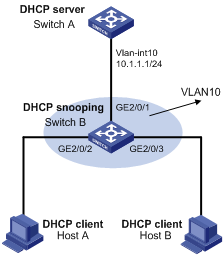
ARP Detection Configuration Example
Network requirements
l Configure Switch A as a DHCP server and enable DHCP snooping on Switch B. Enable ARP detection for VLAN 10 to allow only packets from valid clients to pass.
l Configure Host A and Host B as DHCP clients.
Network diagram
Figure 3-1 Network diagram for ARP detection configuration
Configuration procedure
1) Add all the ports on Switch B into VLAN 10, and configure the IP address of VLAN-interface 10 on Switch A (the configuration procedure is omitted).
2) Configure Switch A as a DHCP server
<SwitchA> system-view
[SwitchA] dhcp enable
[SwitchA] dhcp server ip-pool 0
[SwitchA-dhcp-pool-0] network 10.1.1.0 mask 255.255.255.0
[SwitchA-dhcp-pool-0] quit
3) Configure Host A and Host B as DHCP clients (the configuration procedure is omitted).
4) Configure Switch B
# Enable DHCP snooping.
<SwitchB> system-view
[SwitchB] dhcp-snooping
[SwitchB] interface gigabitethernet 2/0/1
[SwitchB-GigabitEthernet2/0/1] dhcp-snooping trust
[SwitchB-GigabitEthernet2/0/1] quit
# Enable ARP detection for VLAN 10. Configure the upstream port as a trusted port and the downstream ports as untrusted ports (a port is an untrusted port by default).
<SwitchB> system-view
[SwitchB] vlan 10
[SwitchB-vlan10] arp detection enable
[SwitchB-vlan10] interface gigabitethernet 2/0/1
[SwitchB-GigabitEthernet2/0/1] arp detection trust
# Enable the checking of the MAC addresses and IP addresses of ARP packets.
[SwitchB] arp detection validate dst-mac ip src-mac
# Specify the ARP packet rate on GigabitEthernet2/0/2 and GigabitEthernet2/0/3 as 150 pps.
[SwitchB] interface GigabitEthernet2/0/2
[SwitchB-GigabitEthernet2/0/2] arp rate-limit rate 150 drop
[SwitchB-GigabitEthernet2/0/2] quit
[SwitchB] interface gigabitethernet 2/0/3
[SwitchB-GigabitEthernet2/0/3] arp rate-limit rate 150 drop
[SwitchB-GigabitEthernet2/0/3] quit
