- Table of Contents
-
- 02-IP Services Volume
- 00-IP Services Volume Organization
- 01-IP Addressing Configuration
- 02-ARP Configuration.doc
- 03-DHCP Configuration.doc
- 04-DNS Configuration
- 05-IP Performance Configuration
- 06-UDP Helper Configuration
- 07-URPF Configuration
- 08-IPv6 Basics Configuration
- 09-Dual Stack Configuration
- 10-Tunneling Configuration
- 11-sFlow Configuration
- Related Documents
-
| Title | Size | Download |
|---|---|---|
| 10-Tunneling Configuration | 236.02 KB |
Tunneling Configuration Task List
Configuring IPv6 Manual Tunnel
6to4 Tunnel Configuration Example
Displaying and Maintaining Tunneling Configuration
Troubleshooting Tunneling Configuration
When configuring tunneling, go to these sections for information you are interested in:
l Tunneling Configuration Task List
l Configuring IPv6 Manual Tunnel
l Displaying and Maintaining Tunneling Configuration
l Troubleshooting Tunneling Configuration
![]()
l EA boards (such as LSQ1GP12EA and LSQ1TGX1EA) do not support IPv6 features.
l The term “router” or the router icon in this document refers to a router in a generic sense or a Layer 3 Ethernet switch running a routing protocol.
l A tunnel interface number is in the A/B/C format, where A, B, and C represent the slot number of a card, the slot number of a sub-card, and the tunnel interface number, respectively. A and B vary with devices while C ranges from 0 to 1023.
Introduction to Tunneling
The expansion of the Internet results in scarce IPv4 addresses. The technologies such as temporary IPv4 address allocation and Network Address Translation (NAT) relieve the problem of IPv4 address shortage to some extent. However, these technologies not only increase the overhead in address resolution and processing, but also lead to upper-layer application failures. Furthermore, they will still face the problem that IPv4 addresses will eventually be used up. Internet Protocol Version 6 (IPv6) adopting the 128-bit addressing scheme completely solves the above problem. Since significant improvements have been made in address space, security, network management, mobility, and QoS, IPv6 becomes one of the core standards for the next generation Internet protocol. IPv6 is compatible with all protocols except IPv4 in the TCP/IP suite. Therefore, IPv6 can completely take the place of IPv4.
Before IPv6 becomes the dominant protocol, networks using the IPv6 protocol stack are expected to communicate with the Internet using IPv4. Therefore, an IPv6-IPv4 interworking technology must be developed to ensure the smooth transition from IPv4 to IPv6. In addition, the interworking technology should provide efficient, seamless information transfer. The Internet Engineering Task Force (IETF) sets up the next generation transition (NGTRANS) working group to study problems about IPv4-to-IPv6 transition and efficient, seamless IPv4-IPv6 interworking. Currently, multiple transition technologies and interworking solutions are available. With their own characteristics, they are used to solve communication problems in different transition stages under different environments.
Currently, there are three major transition technologies: dual stack (RFC 2893), tunneling (RFC 2893), and NAT-PT (RFC 2766).
Tunneling is an encapsulation technology, which utilizes one network protocol to encapsulate packets of another network protocol and transfer them over the network. A tunnel is a virtual point-to-point connection. In practice, the virtual interface that supports only point-to-point connections is called tunnel interface. One tunnel provides one channel to transfer encapsulated packets. Packets can be encapsulated and decapsulated at both ends of a tunnel. Tunneling refers to the whole process from data encapsulation to data transfer to data decapsulation.
![]()
l For related configuration about the dual protocol stack, refer to Dual Stack Configuration in the IP Services Volume.
l H3C S7500E series Ethernet Switches do not support NAT-PT.
l NTP-related commands are available in tunnel interface view on H3C S7500E series Ethernet Switches, but NTP features cannot be enabled after you execute the NTP commands. For related information about NTP, refer to NTP Configuration.
IPv6 over IPv4 Tunnel
Implementation
The IPv6 over IPv4 tunneling mechanism encapsulates an IPv4 header in IPv6 data packets so that IPv6 packets can pass an IPv4 network through a tunnel to realize interworking between isolated IPv6 networks, as shown in Figure 1-1.
![]()
The devices at both ends of an IPv6 over IPv4 tunnel must support IPv4/IPv6 dual stack.
Figure 1-1 IPv6 over IPv4 tunnel
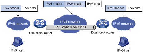
The IPv6 over IPv4 tunnel processes packets in the following way:
1) A host in the IPv6 network sends an IPv6 packet to the device at the source end of the tunnel.
2) After determining according to the routing table that the packet needs to be forwarded through the tunnel, the device at the source end of the tunnel encapsulates the IPv6 packet with an IPv4 header and forwards it through the physical interface of the tunnel.
3) The encapsulated packet goes through the tunnel to reach the device at the destination end of the tunnel. The device at the destination end decapsulates the packet if the destination address of the encapsulated packet is the device itself.
4) The destination device forwards the packet according to the destination address in the decapsulated IPv6 packet. If the destination address is the device itself, the device forwards the IPv6 packet to the upper-layer protocol for processing.
Configured tunnel and automatic tunnel
An IPv6 over IPv4 tunnel can be established between hosts, between hosts and devices, and between devices. The tunnel destination needs to forward packets if the tunnel destination is not the final destination of the IPv6 packet.
Tunnels are divided into configured tunnels and automatic tunnels depending on how the IPv4 address of the tunnel destination is acquired.
l If the destination address of an IPv6 over IPv4 tunnel cannot be acquired from the destination address of IPv6 packets, it needs to be configured manually. Such a tunnel is called a configured tunnel.
l If the interface address of an IPv6 over IPv4 tunnel has an IPv4 address embedded into an IPv6 address, the IPv4 address of the tunnel destination can be acquired automatically. Such a tunnel is called an automatic tunnel.
Type
According to the way an IPv6 packet is encapsulated, IPv6 over IPv4 tunnels supported by S7500E series switches are divided into the following types:
|
Tunnel type |
Tunnel mode |
|
Manually configured tunnel |
IPv6 manual tunnel |
|
Automatic tunnel |
6to4 tunnel |
|
Intra-site automatic tunnel addressing protocol (ISATAP) tunnel |
The configuration parameters for each tunnel mode are listed in the following table:
|
Tunnel mode |
Source/destination IP address of the tunnel |
IP address of the tunnel interface |
|
IPv6 manual tunnel |
The source/destination IP address is a manually configured IPv4 address. |
IPv6 address |
|
6to4 tunnel |
The source IP address is a manually configured IPv4 address, while the destination IP address does not need to be configured. |
6to4 address, in the format of 2002:IPv4-source-address::/48 |
|
ISATAP tunnel |
The source IP address is a manually configured IPv4 address, while the destination IP address does not need to be configured. |
ISATAP address, in the format of Prefix:0:5EFE:IPv4-source-address/64 |
1) IPv6 manually configured tunnel
A manually configured tunnel is a point-to-point link. Each link is a separate tunnel. IPv6 manually configured tunnels are mainly used to provide stable connections for regular secure communication between border routers or between border routers and hosts for access to remote IPv6 networks.
2) 6to4 tunnel
An automatic 6to4 tunnel is a point-to-multipoint tunnel and is used to connect multiple isolated IPv6 networks over an IPv4 network to remote IPv6 networks. The embedded IPv4 address in an IPv6 address is used to automatically acquire the destination IPv4 address of the tunnel.
The automatic 6to4 tunnel adopts 6to4 addresses. The address format is 2002:abcd:efgh:subnet number::interface ID/64, where 2002 represents the fixed IPv6 address prefix, and abcd:efgh represents the 32-bit globally unique source IPv4 address of the 6to4 tunnel, in hexadecimal notation. For example, 1.1.1.1 can be represented by 0101:0101. The part that follows 2002:abcd:efgh uniquely identifies a host in a 6to4 network. The tunnel destination is automatically determined by the embedded IPv4 address, which makes it easy to create a 6to4 tunnel.
Because the 16-bit subnet number of the 64-bit address prefix in 6to4 addresses can be customized and the first 48 bits in the address prefix are fixed to a permanent value and the IPv4 address of the tunnel source or destination, it is possible that IPv6 packets can be forwarded by the tunnel. A 6to4 tunnel interconnects IPv6 networks over an IPv4 network.
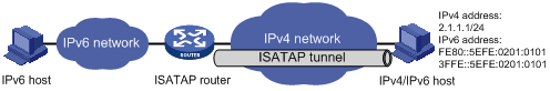
3) ISATAP tunnel
With the application of the IPv6 technology, there will be more and more IPv6 hosts in the existing IPv4 network. The ISATAP tunneling technology provides a satisfactory solution for IPv6 application. An ISATAP tunnel is a point-to-point automatic tunnel. The destination of a tunnel can automatically be acquired from the embedded IPv4 address in the destination address of an IPv6 packet.
When an ISATAP tunnel is used, the destination address of an IPv6 packet and the IPv6 address of a tunnel interface both adopt special ISATAP addresses. The ISATAP address format is prefix(64bit):0:5EFE:ip-address. The 64-bit prefix is the prefix of a valid IPv6 unicast address, while ip-address is a 32-bit source IPv4 address in the form of a.b.c.d or abcd:efgh, which need not be globally unique. Through the embedded IPv4 address, an ISATAP tunnel can automatically be created to transfer IPv6 packets.
The ISATAP tunnel is mainly used for connection between IPv6 routers or between a host and an IPv6 router over an IPv4 network.
Figure 1-2 Principle of ISATAP tunnel
Protocols and Standards
RFC 1853: IP in IP Tunneling
RFC 2473: Generic Packet Tunneling in IPv6 Specification
RFC 2893: Transition Mechanisms for IPv6 Hosts and Routers
RFC 3056: Connection of IPv6 Domains via IPv4 Clouds
RFC 4214: Intra-Site Automatic Tunnel Addressing Protocol (ISATAP)
Tunneling Configuration Task List
Complete the following tasks to configure the tunneling feature:
|
Task |
Remarks |
|
|
Configuring IPv6 over IPv4 tunnel |
Optional |
|
|
Optional |
||
|
Optional |
||
Configuring IPv6 Manual Tunnel
Configuration Prerequisites
l Configure IP addresses for interfaces (such as the VLAN interface and loopback interface) on the device to ensure normal communication.
l Specify one of the above interfaces as the source interface of the tunnel.
l Ensure reachability between the tunnel source and destination addresses.
Configuration Procedure
Follow these steps to configure an IPv6 manual tunnel:
|
To do… |
Use the command… |
Remarks |
|
|
Enter system view |
system-view |
— |
|
|
Enable IPv6 |
ipv6 |
Required By default, the IPv6 packet forwarding function is disabled. |
|
|
Create a tunnel interface and enter tunnel interface view |
interface tunnel number |
Required By default, there is no tunnel interface on the device. |
|
|
Configure an IPv6 address for the tunnel interface |
Configure a global unicast IPv6 address or a site-local address |
ipv6 address { ipv6-address prefix-length | ipv6-address/prefix-length } |
Required Use either command. By default, no IPv6 global unicast address or site-local address is configured for the tunnel interface. |
|
ipv6 address ipv6-address/prefix-length eui-64 |
|||
|
Configure a link-local IPv6 address |
ipv6 address auto link-local |
Optional By default, a link-local address will automatically be created when an IPv6 global unicast address or site-local address is configured. |
|
|
ipv6 address ipv6-address link-local |
|||
|
Specify the IPv6 manual tunnel mode |
tunnel-protocol ipv6-ipv4 |
Optional By default, the tunnel is a IPv6 manual tunnel. The same tunnel mode should be configured at both ends of the tunnel. Otherwise, packet delivery will fail. |
|
|
Configure a source address or interface for the tunnel |
source { ip-address | interface-type interface-number } |
Required By default, no source address or interface is configured for the tunnel. |
|
|
Configure a destination address for the tunnel |
destination ip-address |
Required By default, no destination address is configured for the tunnel. |
|
|
Reference a service loopback group |
service-loopback-group number |
Optional By default, the tunnel does not reference any service loopback group. |
|
![]()
l When you create a tunnel interface on a S7500E switch, the slot of the tunnel interface is recommended to be that of the source interface, namely, the interface sending packets. In this way, the forwarding efficiency can be improved.
l For a S7500E switch, the tunnel configuration is not removed from the active board upon switchover or from the standby board upon its removal. If you configure the same tunnel, the system will display the prompt that the tunnel still exists. To delete the tunnel interface, use the undo interface tunnel command.
l After a tunnel interface is deleted, all the above features configured on the tunnel interface will be deleted.
l If the addresses of the tunnel interfaces at the two ends of a tunnel are not in the same network segment, a forwarding route through the tunnel to the peer must be configured so that the encapsulated packet can be forwarded normally. You need to configure static or dynamic routing at both ends of the tunnel. For detailed configuration, refer to Static Routing Configuration or other routing protocol configuration in the IP Routing Volume.
l When you configure a static route at one tunnel end, you need to configure a route to the destination IPv6 address of the packet, instead of the IPv4 address of the tunnel destination, and set the outbound interface to the tunnel interface at the local end or set the next-hop to the tunnel interface at the peer end. The similar configuration needs to be performed at the other tunnel end.
l When you configure dynamic routing at both tunnel ends, you need to enable the dynamic routing protocol on the tunnel interfaces. For related configurations, refer to related contents in the IP Routing Volume.
l To reference a service loopback group ID on the tunnel interface to receive and send packets, you must have configured the service loopback group. Otherwise, the tunnel interface will not be up to communicate. For creation and configuration of a service loopback group, refer to Service Loopback Group Configuration in the Access Volume.
Configuration Example
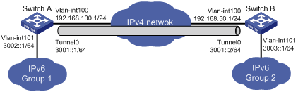
Network requirements
As shown in Figure 1-3, two IPv6 networks are connected to an IPv4 network through Switch A and Switch B respectively. Configure an IPv6 manual tunnel between Switch A and Switch B to make the two IPv6 networks reachable to each other.
Figure 1-3 N Network diagram for an IPv6 manual tunnel (on switches)etwork diagram
Configuration procedure
![]()
Make sure that Switch A and Switch B have the corresponding VLAN interfaces created and are reachable to each other.
l Configuration on Switch A
# Enable IPv6.
<SwitchA> system-view
[SwitchA] ipv6
# Configure an IPv4 address for VLAN-interface 100.
[SwitchA] interface vlan-interface 100
[SwitchA-Vlan-interface100] ip address 192.168.100.1 255.255.255.0
[SwitchA-Vlan-interface100] quit
# Configure an IPv6 address for VLAN-interface 101.
[SwitchA] interface vlan-interface 101
[SwitchA-Vlan-interface101] ipv6 address 3002::1 64
[SwitchA-Vlan-interface101] quit
# Create a service loopback group. Note that you need to disable STP on a port before adding it to a service loopback group.
[SwitchA] service-loopback group 1 type tunnel
[SwitchA] interface GigabitEthernet 2/0/1
[SwitchA-GigabitEthernet2/0/1] stp disable
[SwitchA-GigabitEthernet2/0/1] port service-loopback group 1
[SwitchA-GigabitEthernet2/0/1] quit
# Configure a manual IPv6 tunnel.
[SwitchA] interface tunnel 2/0/0
[SwitchA-Tunnel2/0/0] ipv6 address 3001::1/64
[SwitchA-Tunnel2/0/0] source vlan-interface 100
[SwitchA-Tunnel2/0/0] destination 192.168.50.1
[SwitchA-Tunnel2/0/0] tunnel-protocol ipv6-ipv4
# Reference service loopback group 1 in tunnel interface view.
[SwitchA-Tunnel2/0/0] service-loopback-group 1
[SwitchA-Tunnel2/0/0] quit
# Configure a static route to IPv6 Group 2 through tunnel 2/0/0 on Switch A.
[SwitchA] ipv6 route-static 3003:: 64 tunnel 2/0/0
l Configuration on Switch B
# Enable IPv6.
<SwitchB> system-view
[SwitchB] ipv6
# Configure an IPv4 address for VLAN-interface 100.
[SwitchB] interface vlan-interface 100
[SwitchB-Vlan-interface100] ip address 192.168.50.1 255.255.255.0
[SwitchB-Vlan-interface100] quit
# Configure an IPv6 address for VLAN-interface 101.
[SwitchB] interface vlan-interface 101
[SwitchB-Vlan-interface101] ipv6 address 3003::1 64
[SwitchB-Vlan-interface101] quit
# Create a service loopback group. Note that you need to disable STP on a port before adding it to a service loopback group.
[SwitchB] service-loopback group 1 type tunnel
[SwitchB] interface GigabitEthernet 2/0/1
[SwitchB-GigabitEthernet2/0/1] stp disable
[SwitchB-GigabitEthernet2/0/1] port service-loopback group 1
[SwitchB-GigabitEthernet2/0/1] quit
# Configure an IPv6 manual tunnel.
[SwitchB] interface tunnel 2/0/0
[SwitchB-Tunnel2/0/0] ipv6 address 3001::2/64
[SwitchB-Tunnel2/0/0] source vlan-interface 100
[SwitchB-Tunnel2/0/0] destination 192.168.100.1
[SwitchB-Tunnel2/0/0] tunnel-protocol ipv6-ipv4
# Reference service loopback group 1 in tunnel interface view.
[SwitchB-Tunnel2/0/0] service-loopback-group 1
[SwitchB-Tunnel2/0/0] quit
# Configure a static route to IPv6 Group 1 through tunnel 2/0/0 on Switch B.
[SwitchB] ipv6 route-static 3002:: 64 tunnel 2/0/0
Configuration verification
After the above configurations, display the status of the tunnel interfaces on Switch A and Switch B, respectively.
[SwitchA] display ipv6 interface tunnel 2/0/0 verbose
Tunnel2/0/0 current state :UP
Line protocol current state :UP
IPv6 is enabled, link-local address is FE80::C0A8:6401
Global unicast address(es):
3000::1, subnet is 3000::/64
Joined group address(es):
FF02::1:FFA8:6401
FF02::1:FF00:1
FF02::1:FF00:0
FF02::2
FF02::1
MTU is 1480 bytes
ND reachable time is 30000 milliseconds
ND retransmit interval is 1000 milliseconds
Hosts use stateless autoconfig for addresses
IPv6 Packet statistics:
InReceives: 55
...
[SwitchB] display ipv6 interface tunnel 2/0/0 verbose
Tunnel2/0/0 current state :UP
Line protocol current state :UP
IPv6 is enabled, link-local address is FE80::C0A8:3201
Global unicast address(es):
3000::1, subnet is 3000::/64
Joined group address(es):
FF02::1:FFA8:3201
FF02::1:FF00:1
FF02::1:FF00:0
FF02::2
FF02::1
MTU is 1480 bytes
ND reachable time is 30000 milliseconds
ND retransmit interval is 1000 milliseconds
Hosts use stateless autoconfig for addresses
IPv6 Packet statistics:
InReceives: 55
...
# Ping the IPv6 address of VLAN-interface 101 at the peer end from Switch A.
[SwitchA] ping ipv6 3003::1
PING 3003::1 : 56 data bytes, press CTRL_C to break
Reply from 3003::1
bytes=56 Sequence=1 hop limit=64 time = 1 ms
Reply from 3003::1
bytes=56 Sequence=2 hop limit=64 time = 1 ms
Reply from 3003::1
bytes=56 Sequence=3 hop limit=64 time = 1 ms
Reply from 3003::1
bytes=56 Sequence=4 hop limit=64 time = 1 ms
Reply from 3003::1
bytes=56 Sequence=5 hop limit=64 time = 1 ms
--- 3003::1 ping statistics ---
5 packet(s) transmitted
5 packet(s) received
0.00% packet loss
round-trip min/avg/max = 1/1/1 ms
Configuring 6to4 Tunnel
Configuration Prerequisites
l Configure IP addresses for interfaces (such as the VLAN interface and loopback interface) on the device to ensure normal communication.
l Specify one of the above interfaces as the source interface of the tunnel.
l Ensure reachability between the tunnel source and destination addresses.
Configuration Procedure
Follow these steps to configure a 6to4 tunnel:
|
To do… |
Use the command… |
Remarks |
|
|
Enter system view |
system-view |
— |
|
|
Enable IPv6 |
ipv6 |
Required By default, the IPv6 packet forwarding function is disabled. |
|
|
Create a tunnel interface and enter tunnel interface view |
interface tunnel number |
Required By default, there is no tunnel interface on the device. |
|
|
Configure an IPv6 address for the tunnel interface |
Configure an IPv6 global unicast address or a site-local address |
ipv6 address { ipv6-address prefix-length | ipv6-address/prefix-length } |
Required. Use either command. By default, no IPv6 global unicast address or site-local address is configured for the tunnel interface. |
|
ipv6 address ipv6-address/prefix-length eui-64 |
|||
|
Configure an IPv6 link-local address |
ipv6 address auto link-local |
Optional By default, a link-local address will automatically be generated when an IPv6 global unicast address or site-local address is configured. |
|
|
ipv6 address ipv6-address link-local |
|||
|
Set a 6to4 tunnel |
tunnel-protocol ipv6-ipv4 6to4 |
Required By default, the tunnel is a IPv6 manual tunnel. The same tunnel mode should be configured at both ends of the tunnel. Otherwise, packet delivery will fail. |
|
|
Configure a source address or interface for the tunnel |
source { ip-address | interface-type interface-number } |
Required By default, no source address or interface is configured for the tunnel. |
|
|
Reference a service loopback group |
service-loopback-group number |
Optional By default, no service loopback group is referenced. |
|
![]()
l No destination address needs to be configured for a 6to4 tunnel because the destination address can automatically be obtained from the IPv4 address embedded in the 6to4 IPv6 address.
l When you create a tunnel interface on a S7500E switch, the slot of the tunnel interface is recommended to be that of the source interface, namely, the interface sending packets. In this way, the forwarding efficiency can be improved.
l For a S7500E switch, the tunnel configuration is not removed from the active board upon switchover or from the standby board upon its removal. If you configure the same tunnel, the system will display the prompt that the tunnel still exists. To delete the tunnel interface, use the undo interface tunnel command.
l If the addresses of the tunnel interfaces at the two ends of a tunnel are not in the same network segment, a route to the peer must be configured so that the encapsulated packet can be forwarded normally. You can configure static or dynamic routing. Automatic tunnels do not support dynamic routing. You need to configure a route to the peer at both end of the tunnel. For the detailed configuration, refer to Static Routing Configuration or other routing protocol configuration in the IP Routing Volume.
l The automatic tunnel interfaces using the same encapsulation protocol cannot share the same source IP address.
l When you configure a static route at one tunnel end, you need to configure a route to the destination IPv6 address of the packet, instead of the IPv4 address of the tunnel destination, and set the outbound interface to the tunnel interface at the local end or set the next-hop to the tunnel interface at the peer end. The similar configuration needs to be performed at the other tunnel end.
l To reference a service loopback group on the tunnel interface to receive and send packets, you must have configured the service loopback group. Otherwise, the tunnel interface will not be up to communicate. For creation and configuration of a service loopback group, refer to Service Loopback Group Configuration in the Access Volume.
6to4 Tunnel Configuration Example
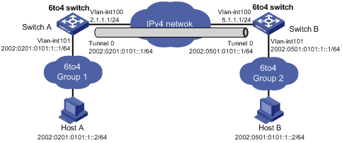
Network requirements
As shown in Figure 1-4, two 6to4 networks are connected to an IPv4 network through two 6to4 switches (Switch A and Switch B) respectively. Configure a 6to4 tunnel to make Host A and Host B reachable to each other.
To enable communication between 6to4 networks, you need to configure 6to4 addresses for 6to4 switches and hosts in the 6to4 networks.
l The IPv4 address of VLAN-interface 100 on Switch A is 2.1.1.1/24, and the corresponding 6to4 prefix is 2002:0201:0101::/48 after it is translated to an IPv6 address. Assign interface tunnel 2/0/0 to subnet 2002:0201:0101::/64 and VLAN-interface 101 to subnet 2002:0201:0101:1::/64.
l The IPv4 address of VLAN-interface 100 on Switch B is 5.1.1.1/24, and the corresponding 6to4 prefix is 2002:0501:0101::/48 after it is translated to an IPv6 address. Assign interface tunnel 2/0/0 to subnet 2002:0501:0101::/64 and VLAN-interface 101 to subnet 2002:0501:0101:1::/64.
Network diagram
Figure 1-4 Network diagram for a 6to4 tunnel (on switches)
Configuration procedure
![]()
Make sure that Switch A and Switch B have the corresponding VLAN interfaces created and are reachable to each other.
l Configuration on Switch A
# Enable IPv6.
<SwitchA> system-view
[SwitchA] ipv6
# Configure an IPv4 address for VLAN-interface 100.
[SwitchA] interface vlan-interface 100
[SwitchA-Vlan-interface100] ip address 2.1.1.1 24
[SwitchA-Vlan-interface100] quit
# Configure an IPv6 address for VLAN-interface 101.
[SwitchA] interface vlan-interface 101
[SwitchA-Vlan-interface101] ipv6 address 2002:0201:0101:1::1/64
[SwitchA-Vlan-interface101] quit
# Create a service loopback group. Note that you need to disable STP on a port before adding it to a service loopback group.
[SwitchA] service-loopback group 1 type tunnel
[SwitchA] interface GigabitEthernet 2/0/1
[SwitchA-GigabitEthernet2/0/1] stp disable
[SwitchA-GigabitEthernet2/0/1] port service-loopback group 1
[SwitchA-GigabitEthernet2/0/1] quit
# Configure a 6to4 tunnel.
[SwitchA] interface tunnel 2/0/0
[SwitchA-Tunnel2/0/0] ipv6 address 2002:201:101::1/64
[SwitchA-Tunnel2/0/0] source vlan-interface 100
[SwitchA-Tunnel2/0/0] tunnel-protocol ipv6-ipv4 6to4
# Reference service loopback group 1 in tunnel interface view.
[SwitchA-Tunnel2/0/0] service-loopback-group 1
[SwitchA-Tunnel2/0/0] quit
# Configure a static route whose destination address is 2002::/16 and next-hop is the tunnel interface.
[SwitchA] ipv6 route-static 2002:: 16 tunnel 2/0/0
l Configuration on Switch B
# Enable IPv6.
<SwitchB> system-view
[SwitchB] ipv6
# Configure an IPv4 address for VLAN-interface 100.
[SwitchB] interface vlan-interface 100
[SwitchB-Vlan-interface100] ip address 5.1.1.1 24
[SwitchB-Vlan-interface100] quit
# Configure an IPv6 address for VLAN-interface 101.
[SwitchB] interface vlan-interface 101
[SwitchB-Vlan-interface101] ipv6 address 2002:0501:0101:1::1/64
[SwitchB-Vlan-interface101] quit
# Create a service loopback group. Note that you need to disable STP on a port before adding it to a service loopback group.
[SwitchB] service-loopback group 1 type tunnel
[SwitchB] interface GigabitEthernet 2/0/1
[SwitchB-GigabitEthernet2/0/1] stp disable
[SwitchB-GigabitEthernet2/0/1] port service-loopback group 1
[SwitchB-GigabitEthernet2/0/1] quit
# Configure the 6to4 tunnel.
[SwitchB] interface tunnel 2/0/0
[SwitchB-Tunnel2/0/0] ipv6 address 2002:0501:0101::1/64
[SwitchB-Tunnel2/0/0] source vlan-interface 100
[SwitchB-Tunnel2/0/0] tunnel-protocol ipv6-ipv4 6to4
# Reference service loopback group 1 in tunnel interface view.
[SwitchB-Tunnel2/0/0] service-loopback-group 1
[SwitchB-Tunnel2/0/0] quit
# Configure a static route whose destination address is 2002::/16 and the next hop is the tunnel interface.
[SwitchB] ipv6 route-static 2002:: 16 tunnel 2/0/0
Configuration verification
After the above configuration, ping Host B from Host A or ping Host A from Host B.
D:\>ping6 -s 2002:201:101:1::2 2002:501:101:1::2
Pinging 2002:501:101:1::2
from 2002:201:101:1::2 with 32 bytes of data:
Reply from 2002:501:101:1::2: bytes=32 time=13ms
Reply from 2002:501:101:1::2: bytes=32 time=1ms
Reply from 2002:501:101:1::2: bytes=32 time=1ms
Reply from 2002:501:101:1::2: bytes=32 time<1ms
Ping statistics for 2002:501:101:1::2:
Packets: Sent = 4, Received = 4, Lost = 0 (0% loss),
Approximate round trip times in milli-seconds:
Minimum = 0ms, Maximum = 13ms, Average = 3ms
Configuring ISATAP Tunnel
Configuration Prerequisites
l Configure IP addresses for interfaces (such as the VLAN interface and loopback interface) on the device to ensure normal communication.
l Specify one of the above interfaces as the source interface of the tunnel.
l Ensure reachability between the tunnel source and destination addresses.
Configuration Procedure
Follow these steps to configure an ISATAP tunnel:
|
To do… |
Use the command… |
Remarks |
|
|
Enter system view |
system-view |
— |
|
|
Enable IPv6 |
ipv6 |
Required By default, the IPv6 forwarding function is disabled. |
|
|
Create a tunnel interface and enter tunnel interface view |
interface tunnel number |
Required By default, there is no tunnel interface on the device. |
|
|
Configure an IPv6 address for the tunnel interface |
Configure an IPv6 global unicast address or site-local address |
ipv6 address { ipv6-address prefix-length | ipv6-address/prefix-length } |
Required. Use either command. By default, no IPv6 global unicast address is configured for the tunnel interface. |
|
ipv6 address ipv6-address/prefix-length eui-64 |
|||
|
Configure an IPv6 link-local address |
ipv6 address auto link-local |
Optional By default, a link-local address will automatically be generated when an IPv6 global unicast address or link-local address is configured. |
|
|
ipv6 address ipv6-address link-local |
|||
|
Set an ISATAP tunnel |
tunnel-protocol ipv6-ipv4 isatap |
Required By default, the tunnel is a IPv6 manual tunnel. The same tunnel mode should be configured at both ends of the tunnel. Otherwise, packet delivery will fail. |
|
|
Configure a source address or interface for the tunnel |
source { ip-address | interface-type interface-number } |
Required By default, no source address or interface is configured for the tunnel. |
|
|
Reference a service loopback group |
service-loopback-group number |
Optional By default, no service loopback group ID is referenced. |
|
![]()
l When you create a tunnel interface on a S7500E switch, the slot of the tunnel interface is recommended to be that of the source interface, namely, the interface sending packets. In this way, the forwarding efficiency can be improved.
l For a S7500E switch, the tunnel configuration is not removed from the active board upon switchover or from the standby board upon its removal. If you configure the same tunnel, the system will display the prompt that the tunnel still exists. To delete the tunnel interface, use the undo interface tunnel command.
l If the addresses of the tunnel interfaces at the two ends of a tunnel are not in the same network segment, a route to the peer must be configured at both ends so that the encapsulated packet can be forwarded normally. You can configure static or dynamic routing. Automatic tunnels do not support dynamic routing. For the detailed configuration, refer to Static Routing Configuration or other routing protocol configuration in the IP Routing Volume.
l The automatic tunnel interfaces using the same encapsulation protocol cannot share the same source IP address.
l When you configure a static route at one tunnel end, you need to configure a route to the destination IPv6 address of the packet, instead of the IPv4 address of the tunnel destination, and set the outbound interface to the tunnel interface at the local end or set the next-hop to the tunnel interface at the peer end. The similar configuration needs to be performed at the other tunnel end.
l To reference a service loopback group ID on the tunnel interface to receive and send packets, you must have configured the service loopback group. Otherwise, the tunnel interface will not be up to communicate. For creation and configuration of a service loopback group, refer to Service Loopback Group Configuration in the Access Volume.
Configuration Example
Network requirements
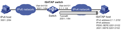
As shown in Figure 1-5, an IPv6 network is connected to an IPv4 network through an ISATAP switch. The destination address of the tunnel is an ISATAP address. It is required that IPv6 hosts in the IPv4 network can access the IPv6 network through the ISATAP tunnel.
Network diagram
Figure 1-5 Network diagram for an ISATAP tunnel
Configuration procedure
![]()
l Make sure that the corresponding VLAN interfaces have been created on the switch.
l Make sure that VLAN-interface 1/1 on the ISATAP switch and the ISATAP host are reachable to each other.
l Configuration on the switch
# Enable IPv6.
<Switch> system-view
[Switch] ipv6
# Configure addresses for interfaces.
[Switch] interface vlan-interface 100
[Switch-Vlan-interface100] ipv6 address 3001::1/64
[Switch-Vlan-interface100] quit
[Switch] interface vlan-interface 101
[Switch-Vlan-interface101] ip address 2.1.1.1 255.0.0.0
[Switch-Vlan-interface101] quit
# Create a service loopback group. Note that you need to disable STP on a port before adding it to a service loopback group.
[Switch] service-loopback group 1 type tunnel
[Switch] interface GigabitEthernet 2/0/1
[Switch-GigabitEthernet2/0/1] stp disable
[Switch-GigabitEthernet2/0/1] port service-loopback group 1
[Switch-GigabitEthernet2/0/1] quit
# Configure an ISATAP tunnel.
[Switch] interface tunnel 2/0/0
[Switch-Tunnel2/0/0] ipv6 address 2001::1/64 eui-64
[Switch-Tunnel2/0/0] source vlan-interface 101
[Switch-Tunnel2/0/0] tunnel-protocol ipv6-ipv4 isatap
# Reference service loopback group 1 in tunnel interface view.
[Switch-Tunnel2/0/0] service-loopback-group 1
# Disable the RA suppression so that hosts can acquire information such as the address prefix from the RA message released by the ISATAP switch.
[Switch-Tunnel2/0/0] undo ipv6 nd ra halt
[Switch-Tunnel2/0/0] quit
# Configure a static route to the ISATAP host.
[Switch] ipv6 route-static 2001:: 16 tunnel 2/0/0
l Configuration on the ISATAP host
The specific configuration on the ISATAP host is related to its operating system. The following example shows the configuration of the host running the Windows XP.
# On a Windows XP-based host, the ISATAP interface is usually interface 2. Configure the IPv4 address of the ISATAP router on the interface to complete the configuration on the host. Before doing that, display the ISATAP interface information:
C:\>ipv6 if 2
Interface 2: Automatic Tunneling Pseudo-Interface
Guid {48FCE3FC-EC30-E50E-F1A7-71172AEEE3AE}
does not use Neighbor Discovery
does not use Router Discovery
routing preference 1
EUI-64 embedded IPv4 address: 0.0.0.0
router link-layer address: 0.0.0.0
preferred link-local fe80::5efe:2.1.1.2, life infinite
link MTU 1280 (true link MTU 65515)
current hop limit 128
reachable time 42500ms (base 30000ms)
retransmission interval 1000ms
DAD transmits 0
default site prefix length 48
# A link-local address (fe80::5efe:2.1.1.2) in the ISATAP format was automatically generated for the ISATAP interface. Configure the IPv4 address of the ISATAP switch on the ISATAP interface.
C:\>ipv6 rlu 2 2.1.1.1
# After carrying out the above command, look at the information on the ISATAP interface.
C:\>ipv6 if 2
Interface 2: Automatic Tunneling Pseudo-Interface
Guid {48FCE3FC-EC30-E50E-F1A7-71172AEEE3AE}
does not use Neighbor Discovery
uses Router Discovery
routing preference 1
EUI-64 embedded IPv4 address: 2.1.1.2
router link-layer address: 2.1.1.1
preferred global 2001::5efe:2.1.1.2, life 29d23h59m46s/6d23h59m46s (public)
preferred link-local fe80::5efe:2.1.1.2, life infinite
link MTU 1500 (true link MTU 65515)
current hop limit 255
reachable time 42500ms (base 30000ms)
retransmission interval 1000ms
DAD transmits 0
default site prefix length 48
# By comparison, it is found that the host acquires the address prefix 2001::/64 and automatically generates the address 2001::5efe:2.1.1.2. Meanwhile, “uses Router Discovery” is displayed, indicating that the router discovery function is enabled on the host. At this time, ping the IPv6 address of the tunnel interface of the switch. If the address is successfully pinged, an ISATAP tunnel is established.
C:\>ping 2001::5efe:2.1.1.1
Pinging 2001::5efe:2.1.1.1 with 32 bytes of data:
Reply from 2001::5efe:2.1.1.1: time=1ms
Reply from 2001::5efe:2.1.1.1: time=1ms
Reply from 2001::5efe:2.1.1.1: time=1ms
Reply from 2001::5efe:2.1.1.1: time=1ms
Ping statistics for 2001::5efe:2.1.1.1:
Packets: Sent = 4, Received = 4, Lost = 0 (0% loss),
Approximate round trip times in milli-seconds:
Minimum = 1ms, Maximum = 1ms, Average = 1ms
Configuration verification
After the above configurations, the ISATAP host can access the host in the IPV6 network.
Displaying and Maintaining Tunneling Configuration
|
To do… |
Use the command… |
Remarks |
|
Display information about a specified tunnel interface |
display interface tunnel [ number ] |
Available in any view |
|
Display IPv6 information related to a specified tunnel interface |
display ipv6 interface tunnel [ number ] [ verbose ] |
Available in any view |
Troubleshooting Tunneling Configuration
Symptom: After the configuration of related parameters such as tunnel source address, tunnel destination address, and tunnel mode, the tunnel interface is still not up.
Solution: Follow the steps below:
1) The common cause is that the physical interface of the tunnel source is not up. Use the display interface tunnel or display ipv6 interface tunnel commands to view whether the physical interface of the tunnel source is up. If the physical interface is down, use the debugging tunnel event command in user view to view the cause.
2) Another possible cause is that the tunnel destination is unreachable. Use the display ipv6 routing-table or display ip routing-table command to view whether the tunnel destination is reachable. If no routing entry is available for tunnel communication in the routing table, configure related routes.
