- Table of Contents
-
- 02-IP Services Volume
- 00-IP Services Volume Organization
- 01-IP Addressing Configuration
- 02-ARP Configuration.doc
- 03-DHCP Configuration.doc
- 04-DNS Configuration
- 05-IP Performance Configuration
- 06-UDP Helper Configuration
- 07-URPF Configuration
- 08-IPv6 Basics Configuration
- 09-Dual Stack Configuration
- 10-Tunneling Configuration
- 11-sFlow Configuration
- Related Documents
-
| Title | Size | Download |
|---|---|---|
| 01-IP Addressing Configuration | 100.68 KB |
Table of Contents
Assigning an IP Address to an Interface
IP Addressing Configuration Example
Displaying and Maintaining IP Addressing
When assigning IP addresses to interfaces on your device, go to these sections for information you are interested in:
l Displaying and Maintaining IP Addressing
IP Addressing Overview
This section covers these topics:
IP Address Classes
IP addressing uses a 32-bit address to identify each host on a network. An example is 01010000100000001000000010000000 in binary. To make IP addresses in 32-bit form easier to read, they are written in dotted decimal notation, each being four octets in length, for example, 10.1.1.1.
Each IP address breaks down into two parts:
l Net-id: First several bits of the IP address defining a network, also known as class bits.
l Host-id: Identifies a host on a network.
For administration sake, IP addresses are divided into five classes. Which class an IP address belongs to depends on the first one to four bits of the net-id, as shown in the following figure (in which the blue parts represent the address class).
Figure 1-1 IP address classes
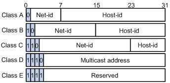
Table 1-1 describes the address ranges of these five classes. Currently, the first three classes of IP addresses are used in quantity.
Table 1-1 IP address classes and ranges
|
Class |
Address range |
Description |
|
A |
0.0.0.0 to 127.255.255.255 |
The IP address 0.0.0.0 is used by a host at bootstrap for temporary communication. This address is never a valid destination address. Addresses starting with 127 are reserved for loopback test. Packets destined to these addresses are processed locally as input packets rather than sent to the link. |
|
B |
128.0.0.0 to 191.255.255.255 |
–– |
|
C |
192.0.0.0 to 223.255.255.255 |
–– |
|
D |
224.0.0.0 to 239.255.255.255 |
Multicast address. |
|
E |
240.0.0.0 to 255.255.255.255 |
Reserved for future use except for the broadcast address 255.255.255.255. |
Special Case IP Addresses
The following IP addresses are for special use, and they cannot be used as host IP addresses:
l IP address with an all-zero net ID: Identifies a host on the local network. For example, IP address 0.0.0.16 indicates the host with a host ID of 16 on the local network.
l IP address with an all-zero host ID: Identifies a network.
l IP address with an all-one host ID: Identifies a directed broadcast address. For example, a packet with the destination address of 192.168.1.255 will be broadcasted to all the hosts on the network 192.168.1.0.
Subnetting and Masking
Subnetting was developed to address the risk of IP address exhaustion resulting from fast expansion of the Internet. The idea is to break a network down into smaller networks called subnets by using some bits of the host-id to create a subnet-id. To identify the boundary between the host-id and the combination of net-id and subnet-id, masking is used. (When subnetting is not adopted, a mask identifies the boundary between the net-id and the host-id.)
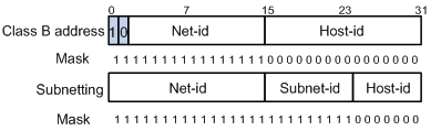
Each subnet mask comprises 32 bits related to the corresponding bits in an IP address. In a subnet mask, the part containing consecutive ones identifies the combination of net-id and subnet-id whereas the part containing consecutive zeros identifies the host-id.
Figure 1-2 shows how a Class B network is subnetted.
Figure 1-2 Subnet a Class B network
When designing your network, you should note that subnetting is somewhat a tradeoff between subnets and accommodated hosts. For example, a Class B network can accommodate 65,534 (216 – 2. Of the two deducted Class B addresses, one with an all-one host-id is the broadcast address and the other with an all-zero host-id is the network address) hosts before being subnetted. After you break it down into 512 (29) subnets by using the first 9 bits of the host-id, you have only 7 bits for the host-id and thus have only 126 (27 – 2) hosts in each subnet. The maximum number of hosts is thus 64,512 (512 × 126), 1022 less after the network is subnetted.
Class A, B, and C networks, before being subnetted, use these default masks (also called natural masks): 255.0.0.0, 255.255.0.0, and 255.255.255.0 respectively.
Configuring IP Addresses
Besides directly assigning an IP address to an interface, you may configure the interface to obtain one through DHCP. If you change the way an interface obtains an IP address, from manual assignment to DHCP, the IP address obtained from DHCP will overwrite the old one manually assigned.
![]()
This chapter only covers how to assign an IP address manually. For other approaches, refer to DHCP Configuration in the IP Services Volume.
This section includes:
l Assigning an IP Address to an Interface
l IP Addressing Configuration Example
Assigning an IP Address to an Interface
Follow these steps to assign an IP address to an interface:
|
To do… |
Use the command… |
Remarks |
|
Enter system view |
system-view |
–– |
|
Enter interface view |
interface interface-type interface-number |
–– |
|
Assign an IP address to the interface |
ip address ip-address { mask | mask-length } [ sub ] |
Required No IP address is assigned by default. Currently, up to seven secondary IP addresses are supported on an interface. |
![]()
l The primary IP address you assigned to the interface can overwrite the old one if there is any.
l You cannot assign secondary IP addresses to an interface that has DHCP configured.
l The primary and secondary IP addresses you assign to the interface can be located on the same network segment. However, this should not violate the rule that different interfaces on your device must reside on different network segments.
IP Addressing Configuration Example
Network requirements
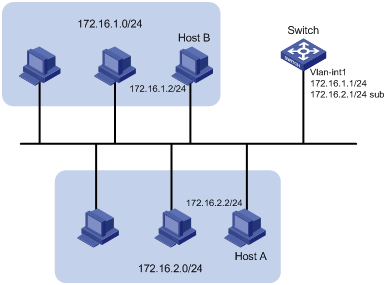
As shown in Figure 1-3, the VLAN-interface 1 on a switch is connected to a LAN comprising two segments: 172.16.1.0/24 and 172.16.2.0/24.
To enable the hosts on the two network segments to access the external network through the switch, and enable the hosts on the two network segments to communicate with each other, do the following:
l Assign a primary IP address and a secondary IP address to VLAN-interface 1 on the switch.
l Set the switch as the gateway on all hosts.
Network diagram
Figure 1-3 Network diagram for IP addressing configuration
Configuration procedure
# Assign a primary IP address and a secondary IP address to VLAN-interface 1.
<Switch> system-view
[Switch] interface vlan-interface 1
[Switch-Vlan-interface1] ip address 172.16.1.1 255.255.255.0
[Switch-Vlan-interface1] ip address 172.16.2.1 255.255.255.0 sub
# Set the gateway address to 172.16.1.1 on the PCs attached to the subnet 172.16.1.0/24, and to 172.16.2.1 on the PCs attached to the subnet 172.16.2.0/24.
# Use the ping command to verify the connectivity between the switch and the hosts on the subnet 172.16.1.0/24.
<Switch> ping 172.16.1.2
PING 172.16.1.2: 56 data bytes, press CTRL_C to break
Reply from 172.16.1.2: bytes=56 Sequence=1 ttl=255 time=25 ms
Reply from 172.16.1.2: bytes=56 Sequence=2 ttl=255 time=27 ms
Reply from 172.16.1.2: bytes=56 Sequence=3 ttl=255 time=26 ms
Reply from 172.16.1.2: bytes=56 Sequence=4 ttl=255 time=26 ms
Reply from 172.16.1.2: bytes=56 Sequence=5 ttl=255 time=26 ms
--- 172.16.1.2 ping statistics ---
5 packet(s) transmitted
5 packet(s) received
0.00% packet loss
round-trip min/avg/max = 25/26/27 ms
The information shown above indicates the switch can communicate with the hosts on the subnet 172.16.1.0/24.
# Use the ping command to verify the connectivity between the switch and the hosts on the subnet 172.16.2.0/24.
<Switch> ping 172.16.2.2
PING 172.16.2.2: 56 data bytes, press CTRL_C to break
Reply from 172.16.2.2: bytes=56 Sequence=1 ttl=255 time=25 ms
Reply from 172.16.2.2: bytes=56 Sequence=2 ttl=255 time=26 ms
Reply from 172.16.2.2: bytes=56 Sequence=3 ttl=255 time=26 ms
Reply from 172.16.2.2: bytes=56 Sequence=4 ttl=255 time=26 ms
Reply from 172.16.2.2: bytes=56 Sequence=5 ttl=255 time=26 ms
--- 172.16.2.2 ping statistics ---
5 packet(s) transmitted
5 packet(s) received
0.00% packet loss
round-trip min/avg/max = 25/25/26 ms
The information shown above indicates the switch can communicate with the hosts on the subnet 172.16.2.0/24.
# Use the ping command to verify the connectivity between hosts on the subnet 172.16.1.0/24 and hosts on subnet 172.16.2.0/24. Ping Host B on Host A to verify that the ping operation is successful.
Displaying and Maintaining IP Addressing
|
To do… |
Use the command… |
Remarks |
|
Display information about a specified or all Layer 3 interfaces |
display ip interface [ interface-type interface-number ] |
Available in any view |
|
Display brief information about a specified or all Layer 3 interfaces |
display ip interface brief [ interface-type [ interface-number ] ] |
Available in any view |
