- Table of Contents
-
- 02-IP Services Volume
- 00-IP Services Volume Organization
- 01-IP Addressing Configuration
- 02-ARP Configuration.doc
- 03-DHCP Configuration.doc
- 04-DNS Configuration
- 05-IP Performance Configuration
- 06-UDP Helper Configuration
- 07-URPF Configuration
- 08-IPv6 Basics Configuration
- 09-Dual Stack Configuration
- 10-Tunneling Configuration
- 11-sFlow Configuration
- Related Documents
-
| Title | Size | Download |
|---|---|---|
| 11-sFlow Configuration | 58.11 KB |
Table of Contents
Troubleshooting sFlow Configuration
The Remote sFlow Collector Cannot Receive sFlow Packets
When configuring sFlow, go to these sections for information you are interested in:
l Troubleshooting sFlow Configuration
sFlow Overview
Introduction to sFlow
Based on packet sampling, Sampled Flow (sFlow) is a traffic monitoring technology mainly used to collect and analyze traffic statistics.
sFlow has the following two sampling mechanisms:
l Packet-based sampling: Samples one packet out of a specified number of packets from a sFlow enabled port.
l Time-based sampling: Samples interface statistics at a specified interval from a sFlow enabled port.
The sFlow system involves an sFlow agent embedded in a device and a remote sFlow collector. The sFlow agent collects traffic from the sFlow enabled ports, encapsulates the information into sFlow packets, and sends the packets to the sFlow collector. The sFlow collector analyzes the sFlow packets and displays the results.
As a traffic monitoring technology, sFlow has the following advantages:
l Supports traffic monitoring on Gigabit and higher-speed networks.
l Provides scalability with one sFlow collector monitoring multiple or more sFlow agents.
l Implements the low-cost sFlow agent.
![]()
Currently, only the sFlow agent function is supported on S7500E Series Ethernet Switches.
Operation of sFlow
sFlow operates as follows:
1) With sFlow enabled, a physical port encapsulates received data into packets and sends them to the sFlow agent.
2) The sFlow agent periodically collects interface statistics on all sFlow enabled ports.
3) When the sFlow packet buffer overflows or the one-second timer expires, the sFlow agent sends the sFlow packets to the specified sFlow collector.
Configuring sFlow
Follow these steps to configure sFlow:
|
Use the command… |
Remarks |
|
|
Enter system view |
system-view |
— |
|
Configure an IP address for the sFlow agent |
sflow agent ip ip-address |
Required Not configured by default. |
|
Specify the IP address and port number of the sFlow collector |
sflow collector ip ip-address [ port port-num ] |
Required Not specified by default. |
|
Set the sFlow interval |
sflow interval interval-time |
Optional 20 seconds by default. |
|
Enter interface view |
interface interface-type interface-number |
— |
|
Enable sFlow in the inbound or outbound direction |
sflow enable { inbound | outbound } |
Required Not enabled by default. |
|
Specify the sFlow sampling mode |
sflow sampling-mode { determine | random } |
Optional random by default. Currently, the determine mode is not supported on S7500E series Ethernet switches. |
|
Specify the sFlow sampling rate |
sflow sampling-rate rate |
Optional 200000 by default. |
![]()
l The sFlow agent and sFlow collector must not have the same IP address.
l Currently, you can specify at most two sFlow collectors on S7500E Series Ethernet Switches.
Displaying sFlow
|
To do… |
Use the command… |
Remarks |
|
Display sFlow configuration information |
display sflow [ slot slot-id ] |
Available in any view |
sFlow Configuration Example
Network requirements
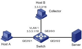
l Host A and Server are connected to Switch through GigabitEthernet 2/0/1 and GigabitEthernet 2/0/2 respectively.
l Host B works as an sFlow collector with IP address 3.3.3.2 and port number 6343, and is connected to Switch through GigabitEthernet 2/0/3.
l GigabitEthernet 2/0/3 belongs to VLAN 1, having an IP address of 3.3.3.1.
Run sFlow agent on Switch, and enable sFlow on GigabitEthernet 2/0/1 to monitor traffic on this interface. Switch sends sFlow packets through GigabitEthernet 2/0/3 to Host B, which then analyzes the sFlow packets and displays the results.
Network diagram
Figure 1-1 Network diagram for sFlow configuration
Configuration procedure
# Configure an IP address for the sFlow agent.
<Switch> system-view
[Switch] sflow agent ip 3.3.3.1
# Specify the IP address and port number of the sFlow collector.
[Switch] sflow collector ip 3.3.3.2
# Set the sFlow interval to 30 seconds.
[Switch] sflow interval 30
# Enable sFlow in both the inbound and outbound directions on GigabitEthernet 2/0/1.
[Switch] interface GigabitEthernet 2/0/1
[Switch-GigabitEthernet2/0/1] sflow enable inbound
[Switch-GigabitEthernet2/0/1] sflow enable outbound
# Specify the traffic sampling rate.
[Switch-GigabitEthernet2/0/1] sflow sampling-rate 100000
# Display the sFlow configuration information.
[Switch-GigabitEthernet2/0/1] display sflow
sFlow Version: 5
sFlow Global Information:
Agent IP:3.3.3.1
Collector IP:3.3.3.2 Port: 6343
Interval(s): 30
sFlow Port Information:
Interface Direction Rate Mode Status
GE2/0/1 In/Out 100000 Random Active
Troubleshooting sFlow Configuration
The Remote sFlow Collector Cannot Receive sFlow Packets
Symptom
The remote sFlow collector cannot receive sFlow packets.
Analysis
l sFlow is not enabled globally because the sFlow agent or/and the sFlow collector are not specified.
l No port is enabled with sFlow to sample data.
l The IP address of the sFlow collector specified on the sFlow agent is different from that of the remote sFlow collector.
l No IP address is configured for the Layer 3 interface on the device, or the IP address is configured, but the UDP packets with the IP address being the source cannot reach the sFlow collector.
l The physical link between the device and the sFlow collector fails.
Solution
1) Check whether sFlow is correctly configured by displaying sFlow configuration with the display sflow command.
2) Check whether the correct IP address is configured for the device to communicate with the sFlow collector.
3) Check whether the physical link between the device and the sFlow collector is normal.
