- Table of Contents
-
- H3C S3610[S5510] Series Ethernet Switches Operation Manual-Release 5303(V1.01)
- 00-1Cover
- 00-2Product Overview
- 01-Login Configuration
- 02-VLAN Configuration
- 03-IP Addressing and Performance Configuration
- 04-QinQ-BPDU Tunneling Configuration
- 05-Port Correlation Configuration
- 06-Link Aggregation Configuration
- 07-MAC Address Table Management Configuration
- 08-IP Source Guard Configuration
- 09-MSTP Configuration
- 10-IPv6 Configuration
- 11-Routing Overview
- 12-IPv4 Routing Configuration
- 13-BFD-GR Configuration
- 14-IPv6 Routing Configuration
- 15-Multicast Protocol Configuration
- 16-802.1x-HABP-MAC Authentication Configuration
- 17-AAA-RADIUS-HWTACACS Configuration
- 18-ARP Configuration
- 19-DHCP Configuration
- 20-ACL Configuration
- 21-QoS Configuration
- 22-Port Mirroring Configuration
- 23-Cluster Management Configuration
- 24-UDP Helper Configuration
- 25-SNMP-RMON Configuration
- 26-NTP Configuration
- 27-DNS Configuration
- 28-File System Management Configuration
- 29-Information Center Configuration
- 30-System Maintaining and Debugging Configuration
- 31-NQA Configuration
- 32-VRRP Configuration
- 33-SSH Configuration
- 34-MCE Configuration
- 35-OAM Configuration
- 36-DLDP Configuration
- 37-RRPP Configuration
- 38-SSL-HTTPS Configuration
- 39-PKI Configuration
- 40-Appendix
- Related Documents
-
| Title | Size | Download |
|---|---|---|
| 05-Port Correlation Configuration | 121.57 KB |
Table of Contents
Chapter 1 Ethernet Port Configuration
1.1 Ethernet Port Configuration
1.1.1 Configuring a Combo Port
1.1.2 Performing Basic Ethernet port Configuration
1.1.3 Configuring Flow Control on an Ethernet Port
1.1.4 Configuring Loopback Testing on an Ethernet Port
1.1.5 Configuring a Port Group
1.1.6 Configuring the Broadcast Storm Suppression Ratio for an Ethernet Port
1.1.7 Setting the Interval for Collecting Ethernet Port Statistics
1.1.8 Enabling the Forwarding of Jumbo Frames
1.1.9 Enabling Loopback Detection on an Ethernet Port
1.1.10 Configuring the Cable Type for an Ethernet Port
1.1.11 Testing the Cable on an Ethernet Port
1.2 Maintaining and Displaying an Ethernet port
Chapter 2 Port Isolation Configuration
2.1 Introduction to Port Isolation
2.2 Configuring an Isolation Group
2.2.1 Adding a Port to an Isolation Group
2.2.2 Configuring the Uplink Port for an Isolation Group
2.3 Displaying and Maintaining an Isolation Group
2.4 Port Isolation Configuration Example
Chapter 1 Ethernet Port Configuration
1.1 Ethernet Port Configuration
Complete the following tasks to perform Ethernet port configuration:
|
Task |
Remarks |
|
Optional |
|
|
Optional |
|
|
Optional |
|
|
Optional |
|
|
Optional |
|
|
Configuring the Broadcast Storm Suppression Ratio for an Ethernet Port |
Optional |
|
Setting the Interval for Collecting Ethernet Port Statistics |
Optional |
|
Optional |
|
|
Optional |
|
|
Optional |
|
|
Optional |
1.1.1 Configuring a Combo Port
I. Introduction to Combo port
Combo ports fall into the following two categories:
l Single Combo port: the two Ethernet ports in the device panel correspond to only one port view, in which the state switch on the two ports can be realized. A single Combo port can be a Layer 2 Ethernet port or a Layer 3 Ethernet interface.
l Dual-Combo port: the two Ethernet ports in the device panel correspond to two port views. The state switchover can be realized in user’s own port view. A dual-Combo port can only be a Layer 2 Ethernet port.
& Note:
Currently, only dual-Combo ports are supported on S3610/S5510 series switches.
II. Configuring Combo port state
Follow these steps to configure the state for a double Combo port:
|
To do... |
Use the command... |
Remarks |
|
Enter system view |
system-view |
— |
|
Enter Ethernet port view |
interface interface-type interface-number |
— |
|
Enable a specified dual-Combo port |
undo shutdown |
Optional By default, out of the two ports in a Combo port, the one with a smaller port ID is enabled. |
For information about Combo ports and the corresponding physical ports, refer to the installation manual.
1.1.2 Performing Basic Ethernet port Configuration
Three types of duplex modes are available to Ethernet ports:
l Full-duplex mode (full). Ports operating in this mode can send and receive packets simultaneously.
l Half-duplex mode (half). Ports operating in this mode can either send or receive packets at a given time.
l Auto-negotiation mode (auto). Ports operating in this mode determine their duplex mode through auto-negotiation.
Similarly, if you configure the transmission rate for an Ethernet port by using the speed command with the auto keyword specified, the transmission rate is determined through auto-negotiation too.
Follow these steps to perform basic Ethernet port configurations:
|
To do... |
Use the command... |
Remarks |
|
Enter system view |
system-view |
— |
|
Enter Ethernet port view |
interface interface-type interface-number |
— |
|
Set the description string |
description text |
Optional By default, the description string is “interface index + Interface”. |
|
Set the duplex mode |
duplex { auto | full | half } |
Optional auto by default. |
|
Set the transmission rate |
speed { 10 | 100 | 1000 | auto } |
Optional auto by default. |
|
Shut down the Ethernet port |
shutdown |
Optional By default, an Ethernet port is in up state. To bring up an Ethernet port, use the undo shutdown command. |
& Note:
l For a Combo port, after you execute the undo shutdown command on the optical port, the electrical port will be shut down automatically and the optical port will be available, and vice versa.
l For a small form-factor pluggable (SFP) port that uses a 100-Mbps module, the duplex mode can only be configured as full, and the port rate can only be 100 Mbps; for a SFP port that uses a 1000-Mbps module, the duplex mode can only be configured as auto or full, and the port rate can be determined through auto negotiation or be 1000 Mbps.
1.1.3 Configuring Flow Control on an Ethernet Port
When flow control is enabled on both sides, if traffic congestion occurs on the ingress port, it will send a Pause frame notifying the egress port to temporarily suspend the sending of packets. The egress port is expected to stop sending any new packets when it receives the Pause frame. In this way, flow controls helps to avoid the dropping of packets. Note that only after both the ingress and the egress ports have turned on their flow control will this be possible.
Follow these steps to enable flow control on an Ethernet port:
|
To do... |
Use the command... |
Remarks |
|
Enter system view |
system-view |
— |
|
Enter Ethernet port view |
interface interface-type interface-number |
— |
|
Enable flow control |
flow-control |
Required Turned off by default |
1.1.4 Configuring Loopback Testing on an Ethernet Port
You can enable loopback testing to check whether the Ethernet port functions properly. Note that no data packets can be forwarded during the testing. Loopback testing falls into the following two categories:
l Internal loopback testing, which is performed within switching chips to test the functions related to the Ethernet ports.
l External loopback testing, which is used to test the hardware functions of an Ethernet port. To perform external loopback testing on an Ethernet port, you need to install a loopback plug on the Ethernet port. In this case, packets sent from the port are received by the same port.
Follow these steps to enable Ethernet port loopback testing:
|
To do... |
Use the command... |
Remarks |
|
Enter system view |
system-view |
— |
|
Enter Ethernet port view |
interface interface-type interface-number |
— |
|
Enable loopback testing |
loopback { external | internal } |
Optional Disabled by default. |
& Note:
l As for the internal loopback test and external loopback test, if a port is down, only the former is available on it; if the port is shut down, both are unavailable.
l The speed, duplex, mdi, and shutdown commands are not applicable during a loopback testing.
l With the loopback testing enabled, the Ethernet port operates in the full duplex mode. With the loopback testing enabled, the original configurations will be restored.
1.1.5 Configuring a Port Group
To make the configuration task easier for users, certain devices allow users to configure on a single port as well as on multiple ports in a port group. In port group view, the user only needs to input the configuration command once on one port and that configuration will apply to all ports in the port group. This effectively reduces redundant configurations.
A Port group belongs to one of the following two categories:
l Manual port group: manually created by users. Multiple Ethernet ports can be added to the same port group;
l Dynamic port group: dynamically created by system, currently mainly applied in link aggregation port groups. A link aggregation port group is automatically created together with the creation of a link aggregation group and cannot be created by users through command line input. Adding or deleting of ports in a link aggregation port group can only be achieved through operations on the link aggregation group.
Follow these steps to enter port group view:
|
To do... |
Use the command... |
Remarks |
|
|
Enter system view |
system-view |
— |
|
|
Enter port group view |
Enter manual port group view |
port-group manual port-group-name |
— |
|
Enter aggregation port group view |
port-group aggregation agg-id |
— |
|
Follow these steps to configure a manual port group:
|
To do... |
Use the command... |
Remarks |
|
Enter system view |
system-view |
— |
|
Create a manual port group |
port-group manual port-group-name |
Required This operation also leads you to manual port group view. |
|
Add Ethernet ports to the manual port group |
group-member interface-list |
Required |
& Note:
For information about link aggregation port group, refer to Link Aggregation Configuration.
1.1.6 Configuring the Broadcast Storm Suppression Ratio for an Ethernet Port
You can suppress broadcast traffic by performing the configuration described in this section. When the broadcast traffic passing through a port exceeds the threshold, the system will discard the extra packets so that the broadcast traffic ratio can drop below the limit to ensure that the network functions properly.
Follow these steps to set broadcast storm suppression ratios for one or multiple Ethernet ports:
|
To do... |
Use the command... |
Remarks |
|
|
Enter system view |
system-view |
— |
|
|
Enter Ethernet port view or port group view |
Enter Ethernet port view |
interface interface-type interface-number |
Use either command. If configured in Ethernet port view, this feature takes effect on the current port only; if configured in port group view, this feature takes effect on all ports in the port group. |
|
Enter port group view |
port-group { manual port-group-name | aggregation agg-id } |
||
|
Configure broadcast storm suppression ratio |
broadcast-suppression ratio |
Optional By default, all broadcast traffic is allowed to pass through a port, that is, broadcast traffic is not suppressed. |
|
& Note:
If you set storm suppression ratios in Ethernet port view or port group view repeatedly for an Ethernet port that belongs to a port group, only the latest settings take effect.
1.1.7 Setting the Interval for Collecting Ethernet Port Statistics
Follow these steps to set the interval for collecting port statistics:
|
To do… |
Use the command… |
Remarks |
|
Enter system view |
system-view |
— |
|
Enter Ethernet port view |
interface interface-type interface-number |
— |
|
Set the interval for collecting port statistics |
flow-interval interval |
Optional 300 seconds by default |
1.1.8 Enabling the Forwarding of Jumbo Frames
Due to tremendous amount of traffic occurring in Ethernet, it is likely that some frames might have a frame size greater than the standard Ethernet frame size. By allowing such frames (called jumbo frames) to pass through Ethernet ports, you can forward frames with a size greater than the standard Ethernet frame size and yet still within the specified parameter range.
In global configuration mode (system view), you can set the length of jumbo frames that can pass through all the Ethernet ports.
Follow these steps to enable the forwarding of jumbo frames
|
To do... |
Use the command... |
Remarks |
|
Enter system view |
system-view |
— |
|
Enable the forwarding of jumbo frames |
jumboframe enable |
By default, the device allows jumbo frames with the length of 1522 bytes to pass through all Ethernet ports. |
1.1.9 Enabling Loopback Detection on an Ethernet Port
The purpose of loopback detection is to detect loops on a port.
When loopback detection is enabled on an Ethernet port, the device will routinely check whether the ports have any external loopback. If it detects a loopback on a port, the device will turn that port under loopback detection mode.
l If loops are detected on a port that is of access type, the port will be shutdown. Meanwhile, trap messages will be sent to the terminal, and the corresponding MAC address forwarding entries will be removed.
l If loops are detected on a port that is of trunk or hybrid type, trap messages are sent to the terminal. If the loopback detection control function is also enabled on the port, the port will be blocked, trap messages will be sent to the terminal, and the corresponding MAC address forwarding entries will be removed.
Follow these steps to configure loopback detection:
|
To do... |
Use the command... |
Remarks |
|
Enter system view |
system-view |
— |
|
Enable global loopback detection |
loopback-detection enable |
Required Disabled by default |
|
Configure the interval for port loopback detection |
loopback-detection interval-time time |
Optional 30 seconds by default |
|
Enter Ethernet port view |
interface interface-type interface-number |
— |
|
Enable loopback detection on a port |
loopback-detection enable |
Required Disabled by default |
|
Enable loopback detection control on a Trunk port or a Hybrid port |
loopback-detection control enable |
Optional Disabled by default |
|
Enable loopback detection in all the VLANs containing the port |
loopback-detection per-vlan enable |
Optional Enabled only in the default VLAN(s) with Trunk port or Hybrid ports |
![]() Caution:
Caution:
l Loopback detection on a given port is enabled only after the loopback-detection enable command has been issued in both system view and the port view of the port.
l Loopback detection on all ports will be disabled after the issuing of the undo loopback-detection enable command under system view.
1.1.10 Configuring the Cable Type for an Ethernet Port
& Note:
The optical ports of combo ports do not support this function.
Follow these steps to configure the cable type for an Ethernet port:
|
To do... |
Use the command... |
Remarks |
|
Enter system view |
system-view |
— |
|
Enter Ethernet port view |
interface interface-type interface-number |
— |
|
Configure the cable type for an Ethernet port |
mdi { across | auto | normal } |
Optional Defaults to auto. That is, system automatically detects the type of cable in use. |
& Note:
The mdi command is not supported on a Combo optical port.
1.1.11 Testing the Cable on an Ethernet Port
& Note:
l The optical ports of a Combo ports do not support this feature. The support of other Ethernet ports for this feature depends on the device model.
l A link in the up state goes down and then up automatically if you perform the operation described in this section on one of the Ethernet ports forming the link.
Follow these steps to test the current operating state of the cable connected to an Ethernet port:
|
To do... |
Use the command... |
Remarks |
|
Enter system view |
system-view |
— |
|
Enter Ethernet port view |
interface interface-type interface-number |
— |
|
Test the current operating state of the cable connected to the port |
virtual-cable-test |
Required |
1.2 Maintaining and Displaying an Ethernet port
|
To do... |
Use the command... |
Remarks |
|
Display the current state of a specified port and related information |
display interface [ interface-type [ interface-number ] ] |
Available in any view |
|
Display a summary of a specified port |
display brief interface [ interface-type [ interface-number ] ] [ | { begin | include | exclude} text ] |
Available in any view |
|
Reset the statistics of a specified port |
reset counters interface [ interface-type [ interface-number ] ] |
Available in user view |
|
Display the Combo ports and the corresponding optical/electrical ports |
display port combo |
Available in any view |
|
Display the current ports of a specified type |
display port { hybrid | trunk } |
Available in any view |
|
Display the information about a manual port group or all the port groups |
display port-group manual [ all | name port-group-name ] |
Available in any view |
|
Display the information about the loopback function |
display loopback-detection |
Available in any view |
Chapter 2 Port Isolation Configuration
2.1 Introduction to Port Isolation
To implement Layer 2 isolation, you can add different ports to different VLANs. However, this will waste the limited VLAN resource. With port isolation, the ports can be isolated within the same VLAN. Thus, you need only to add the ports to the isolation group to implement Layer 2 isolation. This provides you with more secure and flexible networking schemes.
On the current device:
l Currently, only one isolation group is supported on a device, which is created automatically by the system as isolation group 1. The user cannot remove the isolation group or create other isolation groups.
l The number of the ports an isolation group can contain is not limited.
& Note:
l When a port in an aggregation group is configured as the ordinary port for some isolation group, the other ports of the aggregation group can be added to the isolation group as ordinary ports but cannot be configured as uplink ports.
l When a port in an aggregation group is configured as the uplink port for some isolation group, the other ports of the aggregation group cannot be added to the isolation group and the other ports of the device cannot be added to the aggregation group. For details of aggregation group refer to Link Aggregation Configuration.
Port isolation is independent of the VLAN the port belongs to.
l For ports belonging to different VLANs, Layer 2 data can pass only from the ordinary port to the uplink port in the same isolation group unidirectionally.
l Within the same VLAN, there are two types of connectivity of Layer 2 data on ports within and outside the isolation group, as shown in Figure 2-1.
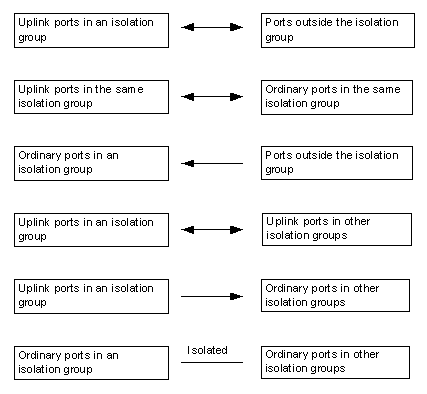
& Note:
The arrows in the above figure indicate the transmission direction of Layer 2 data.
2.2 Configuring an Isolation Group
2.2.1 Adding a Port to an Isolation Group
Follow these steps to add a port to an isolation group:
|
To do… |
Use the command… |
Remarks |
|
|
Enter system view |
system-view |
— |
|
|
Enter Ethernet port view or port group view |
Enter Ethernet port view |
interface interface-type interface-number |
Either of the two is required. Configured in Ethernet port view, the setting is effective on the current port only; configured in port group view, the setting is effective on all ports in the port group. |
|
Enter port group view |
port-group { manual port-group-name | aggregation agg-id } |
||
|
Add the port(s) to the isolation group as ordinary port(s) |
port-isolate enable |
Required By default, an isolation group contains no port. |
|
2.2.2 Configuring the Uplink Port for an Isolation Group
Follow these steps to configure the uplink port for an isolation group:
|
To do… |
Use the command… |
Remarks |
|
Enter system view |
system-view |
— |
|
Enter Ethernet port view |
interface interface-type interface-number |
— |
|
Add the port to the isolation group as the uplink port |
port-isolate uplink-port group |
Required An isolation group has no uplink port by default. |
& Note:
l An isolation group can have only one uplink port. When a user configures multiple ports as the uplink port, only the last one prevails.
l When a port has already been configured as an ordinary port for an isolation group, it cannot be configured as an uplink port, and vice versa.
2.3 Displaying and Maintaining an Isolation Group
|
To do… |
Use the command… |
Remarks |
|
Display the information about an isolation group |
display port-isolate group |
Available in any view |
2.4 Port Isolation Configuration Example
I. Networking Requirement
l Users Host A, Host B, and Host C are connected to Ethernet 1/0/1, Ethernet 1/0/2, and Ethernet 1/0/3 of Device.
l Device is connected to an external network through Ethernet 1/0/4.
l Ethernet 1/0/1, Ethernet 1/0/2, Ethernet 1/0/3, and Ethernet 1/0/4 belong to the same VLAN. It is desired that Host A, Host B, and Host C cannot communicate with each other, but can access the external network.
II. Networking diagram
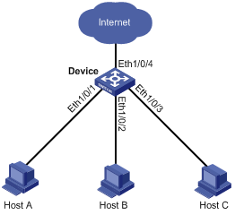
Figure 2-2 Networking diagram for port isolation configuration on a distributed device
III. Configuration procedure
l Configuration procedure on a centralized device
# Add ports Ethernet 1/0/1, Ethernet 1/0/2 and Ethernet 1/0/3 to the isolation group.
<Device> system-view
[Device] interface ethernet 1/0/1
[Device-Ethernet1/0/1] port-isolate enable
[Device-Ethernet1/0/1] quit
[Device] interface ethernet 1/0/2
[Device-Ethernet1/0/2] port-isolate enable
[Device-Ethernet1/0/2] quit
[Device] interface ethernet 1/0/3
[Device-Ethernet1/0/3] port-isolate enable
# Configure port Ethernet 1/0/4 as the uplink port of the isolation group.
[Device-Ethernet1/0/3] quit
[Device] interface ethernet 1/0/4
[Device-Ethernet1/0/4] port-isolate uplink-port
[Device-Ethernet1/0/4] return
# Display the information about the isolation group.
<Device> display port-isolate group
Port-isolate group information:
Uplink port support: YES
Group ID: 1
Uplink port: Ethernet1/0/4
Ethernet1/0/1 Ethernet1/0/2 Ethernet1/0/3