- Table of Contents
-
- H3C S9500 Series Routing Switches Operation Manual-(V1.01)
- 00-1Cover
- 01-Getting Started Operation
- 02-Port Operation
- 03-VLAN-QinQ Operation
- 04-Network Protocol Operation
- 05-Routing Protocol Operation
- 06-Multicast Protocol Operation
- 07-QACL Operation
- 08-MPLS Operation
- 09-STP Operation
- 10-Security Operation
- 11-Reliability Operation
- 12-System Management Operation
- 13-PoE Operation
- 14-NAT-URPF-VPLS Operation
- 15-Integrated Management Operation
- 16-Appendix
- Related Documents
-
| Title | Size | Download |
|---|---|---|
| 10-Security Operation | 382 KB |
Table of Contents
Chapter 1 802.1x Configuration
1.1.1 802.1x Standard Overview
1.1.2 802.1x System Architecture
1.1.3 802.1x Authentication Process
1.1.4 Implementing 802.1x on Ethernet Switches
1.2.1 Enabling/Disabling 802.1x
1.2.2 Setting the Port Access Control Mode
1.2.3 Setting Port Access Control Method
1.2.4 Checking the Users that Log on the Switch via Proxy
1.2.5 Setting Supplicant Number on a Port
1.2.6 Setting the Authentication in DHCP Environment
1.2.7 Configuring Authentication Method for 802.1x User
1.2.9 Setting the Maximum times of authentication request message retransmission
1.2.10 Configuring 802.1x Timers
1.2.11 Enabling/Disabling Quiet-Period Timer
1.3 Displaying and Debugging 802.1x
1.4 Packet Attack Prevention Configuration
1.5 802.1x Configuration Example
Chapter 2 AAA and RADIUS/HWTACACS Protocol Configuration
2.1 AAA and RADIUS/HWTACACS Protocol Overview
2.1.2 RADIUS Protocol Overview
2.1.3 HWTACACS Protocol Overview
2.1.4 Implementing AAA/RADIUS on a Switch
2.2.1 Creating/Deleting an ISP Domain
2.2.2 Configuring Relevant Attributes of an ISP Domain
2.2.3 Configuring Self-Service Server URL
2.2.4 Creating/Deleting a Local User
2.2.5 Setting the Attributes of a Local User
2.2.6 Disconnecting a User by Force
2.2.7 Configuring Dynamic VLAN Delivering
2.3 Configuring RADIUS Protocol
2.3.1 Creating/Deleting a RADIUS scheme
2.3.2 Setting IP Address and Port Number of a RADIUS Server
2.3.3 Setting the RADIUS Packet Encryption Key.
2.3.4 Configuring VPN of RADIUS Server
2.3.5 Setting the Maximum Retry Times for RADIUS Request Packets
2.3.6 Setting RADIUS Server Response Timeout Timer
2.3.7 Setting Quiet Time of RADIUS Server
2.3.8 Enabling the Selection of Radius Accounting Option
2.3.9 Setting a Real-time Accounting Interval
2.3.10 Setting the Maximum Times of Real-time Accounting Request Failing to be Responded
2.3.11 Enabling/Disabling Stopping Accounting Request Buffer
2.3.12 Setting the Maximum Retransmitting Times of Stopping Accounting Request
2.3.13 Setting the Supported Type of RADIUS Server
2.3.14 Setting RADIUS Server State
2.3.15 Setting the Username Format Transmitted to RADIUS Server
2.3.16 Setting the Unit of Data Flow that Transmitted to RADIUS Server
2.3.17 Configuring the Source Address Used by NAS in RADIUS Packets
2.3.18 Configuring a Local RADIUS Authentication Server
2.4 Configuring HWTACACS Protocol
2.4.1 Creating a HWTACAS Scheme
2.4.2 Configuring HWTACACS Authentication Servers
2.4.3 Configuring HWTACACS Authorization Servers.
2.4.4 Configuring HWTACACS Accounting Servers and the Related Attributes
2.4.5 Configuring the Source Address for HWTACACS Packets Sent by NAS
2.4.6 Setting a Key for Securing the Communication with TACACS Server
2.4.7 Setting the Username Format Acceptable to the TACACS Server
2.4.8 Setting the Unit of Data Flows Destined for the TACACS Server
2.4.9 Setting Timers Regarding TACACS Server
2.5 Displaying and Debugging AAA and RADIUS Protocol
2.6 AAA and RADIUS/HWTACACS Protocol Configuration Examples
2.6.1 Configuring Authentication at Remote RADIUS Server
2.6.2 Configuring Authentication at Local RADIUS Authentication Server
2.6.3 Configuring Authentication at Remote TACACS Server
2.7 Troubleshooting AAA and RADIUS/HWTACACS
Chapter 1 802.1x Configuration
1.1 802.1x Overview
1.1.1 802.1x Standard Overview
IEEE 802.1x (hereinafter simplified as 802.1x) is a port-based network access control protocol that is used as the standard for LAN user access authentication.
In the LANs complying with the IEEE 802 standards, the user can access the devices and share the resources in the LAN through connecting the LAN access control device like the LAN Switch. However, in telecom access, commercial LAN (a typical example is the LAN in the office building) and mobile office etc., the LAN providers generally hope to control the user’s access. In these cases, the requirement on the above-mentioned “Port Based Network Access Control” originates.
As the name implies, “Port Based Network Access Control” means to authenticate and control all the accessed devices on the port of LAN access control device. If the user’s device connected to the port can pass the authentication, the user can access the resources in the LAN. Otherwise, the user cannot access the resources in the LAN. It equals that the user is physically disconnected.
802.1x defines port based network access control protocol and only defines the point-to-point connection between the access device and the access port. The port can be either physical or logical. The typical application environment is as follows: Each physical port of the LAN Switch only connects to one user workstation (based on the physical port) and the wireless LAN access environment defined by the IEEE 802.11 standard (based on the logical port), etc.
1.1.2 802.1x System Architecture
The LAN access control device needs to provide the Authenticator System of 802.1x. The devices at the user side such as the computers need to be installed with the 802.1x client Supplicant software, for example, the 802.1x client provided by S9500 (or by Microsoft Windows XP). The 802.1x Authentication Sever system normally stays in the carrier’s AAA center.
Authenticator and Authentication Sever exchange information through EAP (Extensible Authentication Protocol) frames. The Supplicant and the Authenticator exchange information through the EAPoL (Extensible Authentication Protocol over LANs) frame defined by IEEE 802.1x. Authentication data are encapsulated in the EAP frame, which is to be encapsulated in the packets of other AAA upper layer protocols (e.g. RADIUS) so as to go through the complicated network to reach the Authentication Server. Such procedure is called EAP Relay.
There are two types of ports for the Authenticator. One is the Uncontrolled Port, and the other is the Controlled Port. The Uncontrolled Port is always in bi-directional connection state. The user can access and share the network resources any time through the ports. The Controlled Port will be in connecting state only after the user passes the authentication. Then the user is allowed to access the network resources.
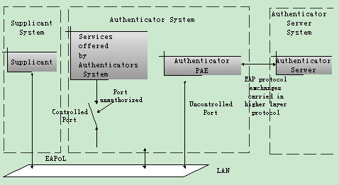
Figure 1-1 802.1x system architecture
1.1.3 802.1x Authentication Process
802.1x configures EAP frame to carry the authentication information. The Standard defines the following types of EAP frames:
l EAP-Packet: Authentication information frame, used to carry the authentication information.
l EAPoL-Start: Authentication originating frame, actively originated by the Supplicant.
l EAPoL-Logoff: Logoff request frame, actively terminating the authenticated state.
l EAPoL-Key: Key information frame, supporting to encrypt the EAP packets.
l EAPoL-Encapsulated-ASF-Alert: Supports the Alerting message of Alert Standard Forum (ASF).
The EAPoL-Start, EAPoL-Logoff and EAPoL-Key only exist between the Supplicant and the Authenticator. The EAP-Packet information is re-encapsulated by the Authenticator System and then transmitted to the Authentication Server System. The EAPoL-Encapsulated-ASF-Alert is related to the network management information and terminated by the Authenticator.
802.1x provides an implementation solution of user ID authentication. However, 802.1x itself is not enough to implement the scheme. The administrator of the access device should configure the AAA scheme by selecting RADIUS or local authentication so as to assist 802.1x to implement the user ID authentication. For detailed description of AAA, refer to the corresponding AAA configuration.
1.1.4 Implementing 802.1x on Ethernet Switches
H3C Series Ethernet Switches not only support the port access authentication method regulated by 802.1x, but also extend and optimize it in the following way:
l Support to connect several End Stations in the downstream via a physical port.
l The access control (or the user authentication method) can be based on port or MAC address.
In this way, the system becomes much securer and easier to manage.
1.2 802.1x Configuration
The configuration tasks of 802.1x itself can be fulfilled in system view of the Ethernet switch. After the global 802.1x is enabled, the user can configure the 802.1x state of the port. The configured items will take effect after the global 802.1x is enabled.
& Note:
When 802.1x is enabled on a port, the max number of MAC address learning which is configured by the command mac-address max-mac-count cannot be configured on the port, and vice versa.
The following sections describe 802.1x configuration tasks.
l Setting the Port Access Control Mode
l Setting Port Access Control Method
l Checking the Users that Log on the Switch via Proxy
l Setting Supplicant Number on a Port
l Setting the Authentication in DHCP Environment
l Configuring Authentication Method for 802.1x User
l Setting the Maximum times of authentication request message retransmission
l Enabling/Disabling Quiet-Period Timer
1.2.1 Enabling/Disabling 802.1x
The following command can be used to enable/disable the 802.1x on the specified port or globally. When it is used in system view, if the parameter interface-list is not specified, 802.1x will be globally enabled. If the parameter interface-list is specified, 802.1x will be enabled on the specified port. When this command is used in Ethernet port view, the parameter interface-list cannot be input and 802.1x can only be enabled on the current port.
Perform the following configuration in system view or Ethernet port view.
Table 1-1 Enable/Disable 802.1x
|
Operation |
Command |
|
Enable the 802.1x |
dot1x [ interface interface-list ] |
|
Disable the 802.1x |
undo dot1x [ interface interface-list ] |
By default, 802.1x authentication has not been enabled globally and on any port.
You cannot configure 802.1x on a port before you enable it globally. And you must disable 802.1x on each port before you disable 802,1x globally.
1.2.2 Setting the Port Access Control Mode
The following commands can be used for setting 802.1x access control mode on the specified port. When no port is specified, the access control mode of all ports is configured.
Perform the following configuration in system view or Ethernet port view.
Table 1-2 Set the port access control mode
|
Operation |
Command |
|
Set the port access control mode |
dot1x port-control { authorized- force | unauthorized-force | auto } [ interface interface-list ] |
|
Restore the default access control mode of the port |
undo dot1x port-control [ interface interface-list ] |
auto (automatic identification mode, which is also called protocol control mode). That is, the initial state of the port is unauthorized. It only permits EAPoL packets receiving/transmitting and does not permit the user to access the network resources. If the authentication flow is passed, the port will be switched to the authorized state and permit the user to access the network resources.
The authorized-force keyword specifies the port to operate in authorized-force mode. Ports in this mode are always authorized. Users can access a network through this kind of port without being authorized.
The unauthorized-force keyword specifies the port to operate in unauthorized-force mode. Ports in this mode are always unauthorized. They do not respond to authorization requests. Users cannot access a network through this kind of port.
By default, the mode of 802.1x performing access control on the port is auto (automatic identification mode).
1.2.3 Setting Port Access Control Method
The following commands are used for setting 802.1x access control method on the specified port. When no port is specified in system view, the access control method of all ports is configured.
Perform the following configuration in system view or Ethernet port view.
Table 1-3 Set port access control method
|
Operation |
Command |
|
Set port access control method |
dot1x port-method { macbased | portbased } [ interface interface-list ] |
|
Restore the default port access control method |
undo dot1x port-method [ interface interface-list ] |
The macbased keyword specifies to authenticate each user accessing through the port. And disconnection of a user does not affect other users. Whereas if you specify the portbased keyword, users can access a network without being authenticated if a user passes the authentication previously. But these users are denied when the one who passes the authentication first goes offline.
By default, 802.1x authentication method on the port is macbased. That is, authentication is performed based on MAC addresses.
1.2.4 Checking the Users that Log on the Switch via Proxy
The following commands are used for checking the users that log on the switch via proxy.
Perform the following configuration in system view or Ethernet port view.
Table 1-4 Check the users that log on the switch via proxy
|
Operation |
Command |
|
Enable the check for access users via proxy |
dot1x supp-proxy-check { logoff | trap } [ interface interface-list ] |
|
Cancel the check for access users via proxy |
undo dot1x supp-proxy-check { logoff | trap } [ interface interface-list ] |
These commands take effect on the ports specified by the interface-list parameter when executed in system view. The parameter interface-list cannot be input when the command is executed in Ethernet Port view and it has effect only on the current interface. After globally enabling proxy user detection and control in system view, only if you enable this feature on a specific port can this configuration take effects on the port.
1.2.5 Setting Supplicant Number on a Port
The following commands are used for setting number of users allowed by 802.1x on specified port. When no port is specified, all the ports accept the same number of supplicants.
Perform the following configuration in system view or Ethernet port view.
Table 1-5 Setting maximum number of users via specified port
|
Operation |
Command |
|
Set maximum number of users via specified port |
dot1x max-user user-number [ interface interface-list ] |
|
Restore the maximum number of users on the port to the default value |
undo dot1x max-user [ interface interface-list ] |
By default, 802.1x allows up to 1024 supplicants on each port for H3C S9500 Series Routing Switches (hereinafter referred to as S9500 series), and an S9500 series routing switch can accommodate total of 2048 supplicants.
1.2.6 Setting the Authentication in DHCP Environment
If in DHCP environment the users configure static IP addresses, you can set 802.1x to disable the switch to trigger the user ID authentication over them with the following command.
Perform the following configuration in system view.
Table 1-6 Set the Authentication in DHCP Environment
|
Operation |
Command |
|
Disable the switch to trigger the user ID authentication over the users who configure static IP addresses in DHCP environment |
dot1x dhcp-launch |
|
Enable the switch to trigger the authentication over them |
undo dot1x dhcp-launch |
By default, the switch can trigger the user ID authentication over the users who configure static IP addresses in DHCP environment.
1.2.7 Configuring Authentication Method for 802.1x User
The following commands can be used to configure the authentication method for 802.1x user. Three kinds of methods are available: PAP authentication (RADIUS server must support PAP authentication), CHAP authentication (RADIUS server must support CHAP authentication), EAP relay authentication (switch send authentication information to RADIUS server in the form of EAP packets directly and RADIUS server must support EAP authentication).
Perform the following configuration in system view.
Table 1-7 Configure authentication method for 802.1x user
|
Operation |
Command |
|
Configure authentication method for 802.1x user |
dot1x authentication-method { chap | pap | eap md5-challenge} |
|
Restore the default authentication method for 802.1x user |
undo dot1x authentication-method |
By default, CHAP authentication is used for 802.1x user authentication.
1.2.8 Configuring Guest VLAN
If Guest VLAN is enabled, a switch broadcasts active authentication packets to all 802.1x-enabled ports. The ports not sending response packets are added to Guest VLAN when the maximum number of re-authentications is reached. Users in a Guest VLAN can utilize resources in the Guest VLAN without undergoing the 802.1x authentication, but they can utilize the resources outside the Guest VLAN only when they have passed the 802.1x authentication. In this way, unauthenticated users can still perform operations such as accessing some resources with the 802.1x client not installed, and upgrading 802.1x client.
Perform the following configuration in system view or Ethernet interface view.
Table 1-8 Configure Guest VLAN
|
Operation |
Command |
|
Enable Guest VLAN |
dot1x guest-vlan vlan-id [ interface interface-list ] |
|
Disable Guest VLAN |
undo dot1x guest-vlan vlan-id [ interface interface-list ] |
Note that:
l Guest VLAN is only supported when the switch performs port-based authentication.
l A switch can have only one Guest VLAN.
l Users who are not authenticated, fail to be authenticated, or are offline are all members of the Guest VLAN.
l Guest VLANs can only be configured on Access ports.
l You must use an existing VLAN ID, and the corresponding VLAN cannot be a Super VLAN.
l You must perform corresponding configuration manually to isolate the Guest VLAN from other VLAN interfaces.
1.2.9 Setting the Maximum times of authentication request message retransmission
The following commands are used for setting the maximum retransmission times of the authentication request message that the switch sends to the supplicant.
Perform the following configuration in system view.
Table 1-9 Set the maximum times of the authentication request message retransmission
|
Operation |
Command |
|
Set the maximum times of the authentication request message retransmission |
dot1x retry max-retry-value |
|
Restore the default maximum retransmission times |
undo dot1x retry |
By default, the max-retry-value is 2. That is, the switch can retransmit the authentication request message to a supplicant for 2 times at most.
1.2.10 Configuring 802.1x Timers
The following commands are used for configuring the 802.1x timers.
Perform the following configuration in system view.
Table 1-10 Configure 802.1x timers
|
Operation |
Command |
|
Configure timers |
dot1x timer { handshake-period handshake-period-value | quiet-period quiet-period-value | tx-period tx-period-value | supp-timeout supp-timeout-value | server-timeout server-timeout-value } |
|
Restore default settings of the timers |
undo dot1x timer { handshake-period | quiet-period | tx-period | supp-timeout | server-timeout } |
handshake-period: This timer begins after the user has passed the authentication. After setting handshake-period, system will send the handshake packet by the period. Suppose the dot1x retry time is configured as N, the system will consider the user having logged off and set the user as logoff state if system doesn’t receive the response from user for consecutive N times.
handshake-period-value: Handshake period. The value ranges from 1 to 1024 in units of second and defaults to 30.
quiet-period: Specifies the quiet timer. If an 802.1x user has not passed the authentication, the Authenticator will keep quiet for a while (which is specified by quiet-period timer) before launching the authentication again. During the quiet period, the Authenticator does not do anything related to 802.1x authentication.
quiet-period-value: Specifies how long the quiet period is. The value ranges from 10 to 120 in units of second and defaults to 60.
server-timeout: Specifies the timeout timer of an Authentication Server. If an Authentication Server has not responded before the specified period expires, the Authenticator will resend the authentication request.
server-timeout-value: Specifies how long the duration of a timeout timer of an Authentication Server is. The value ranges from 100 to 300 in units of second and defaults to 100 seconds.
supp-timeout: Specifies the authentication timeout timer of a Supplicant. After the Authenticator sends Request/Challenge request packet which requests the MD5 encrypted text, the supp-timeout timer of the Authenticator begins to run. If the Supplicant does not respond back successfully within the time range set by this timer, the Authenticator will resend the above packet.
supp-timeout-value: Specifies how long the duration of an authentication timeout timer of a Supplicant is. The value ranges from 10 to 120 in units of second and defaults to 30.
tx-period: Specifies the transmission timeout timer. After the Authenticator sends the Request/Identity request packet which requests the user name or user name and password together, the tx-period timer of the Authenticator begins to run. If the Supplicant does not respond back with authentication reply packet successfully, then the Authenticator will resend the authentication request packet.
tx-period-value: Specifies how long the duration of the transmission timeout timer is. The value ranges from 10 to 120 in units of second and defaults to 30.
& Note:
It is recommended to configure different handshake period value and handshake timeout times according to the number of users:
l When the number of users is 2048, the handshake period value should be no smaller than 2 minutes, and the handshake timeout times should be no less than 3 times;
l When the number of users is 1024, the handshake period value should be no smaller than 1 minutes, and the handshake timeout times should be no less than 3 times
l When the number of users is 512, the handshake period value should be no smaller than 30 seconds, and the handshake timeout times should be no less than 2 times.
1.2.11 Enabling/Disabling Quiet-Period Timer
You can use the following commands to enable/disable a Quiet-Period timer of an Authenticator (such as a H3C Series Switch). If an 802.1x user has not passed the authentication, the Authenticator will keep quiet for a while (which is specified by dot1x timer quiet-period command) before launching the authentication again. During the Quiet Period, the Authenticator does not do anything related to 802.1x authentication.
Perform the following configuration in system view.
Table 1-11 Enable/Disable a Quiet-Period timer
|
Operation |
Command |
|
Enable a quiet-period timer |
dot1x quiet-period |
|
Disable a quiet-period timer |
undo dot1x quiet-period |
By default, Quiet-Period timer is disabled.
1.3 Displaying and Debugging 802.1x
Table 1-12 Display and debug 802.1x
|
Operation |
Command |
|
Display the configuration, running and statistics information of 802.1x |
display dot1x [ sessions | statistics | enabled-interface | guest vlan ] [ interface interface-list | sessions | statistics] |
|
Reset the 802.1x statistics information |
reset dot1x statistics [ interface interface-list ] |
|
Enable the error/event/packet/all debugging of 802.1x |
debugging dot1x { error | event | packet | all } |
|
Disable the error/event/packet/all debugging of 802.1x. |
undo debugging dot1x { error | event | packet | all } |
1.4 Packet Attack Prevention Configuration
With the expansion of Internet scale and the increase of Internet users, the possibility that networking equipment gets attacked is increasing. Specific to some typical attack modes, the S9500 series switches provides a series of schemes of preventing attacks against packets to protect the networking equipment against attacked from IP, ARP, 802.1x and unknown multicast packets.
l IP Packet attack: It refers to such a situation that the S9500 switch receives too many IP packets whose destination addresses and VLAN interface addresses are within the same network segment, while the corresponding forwarding entries do not exist on the switch. Such packets will be delivered to the CPU for processing. They occupy lots of CPU resources, and even affect the forwarding of normal packets.
l ARP packet attack: It refers to such a situation that the S9500 switch receives a large number of ARP request packets with the same or similar source MAC addresses. These packets affect the normal ARP learning.
l 802.1x packet attack: It refers to such a situation that the S9500 switch receives a large number of 8021.x authentication packets with the same or similar source MAC addresses. These packets largely occupy the CPU resources.
Perform the following configuration in system view.
Table 1-13 Enable/disable packet attack prevention
|
Operation |
Command |
|
Enable/Disable packet attack prevention |
anti-attack { arp | dot1x | ip } { disable | enable } |
By default, IP packet attack prevention is enabled while ARP packet attack prevention and dot1x packet attack prevention are disabled by default.
1.5 802.1x Configuration Example
I. Network requirements
As shown in Figure 1-2, the workstation of a user is connected to the port Ethernet 3/1/1 of the Switch.
The switch administrator will enable 802.1x on all the ports to authenticate the supplicants so as to control their access to the Internet. The access control mode is configured as based on the MAC address
All the supplicants belong to the default domain H3C.net, which can contain up to 30 users. RADIUS authentication is performed first. If there is no response from the RADIUS server, local authentication will be performed. For accounting, if the RADIUS server fails to account, the user will be disconnected. In addition, when the user is accessed, the domain name does not follow the user name. Normally, if the user’s traffic is less than 2000 Byte/s consistently over 20 minutes, he will be disconnected.
A server group, consisting of two RADIUS servers at 10.11.1.1 and 10.11.1.2 respectively, is connected to the switch. The former one acts as the primary-authentication/secondary-accounting server. The latter one acts as the secondary-authentication/primary-accounting server. Set the encryption key as “name” when the system exchanges packets with the authentication RADIUS server and “money” when the system exchanges packets with the accounting RADIUS server. Configure the system to retransmit packets to the RADIUS server if no response received in 5 seconds. Retransmit the packet no more than 5 times in all. Configure the system to transmit a real-time accounting packet to the RADIUS server every 15 minutes. The system is instructed to transmit the user name to the RADIUS server after removing the user domain name from the user name.
The user name of the local 802.1x access user is localuser and the password is localpass (input in plain text). The idle cut function is enabled.
II. Network diagram
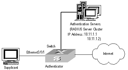
Figure 1-2 Enable 802.1x and RADIUS to perform AAA on the supplicant
III. Configuration procedure
& Note:
The following examples concern most of the AAA/RADIUS configuration commands. For details, refer to the chapter AAA and RADIUS/HWTACACS Protocol Configuration.
The configurations of access user workstation is omitted.
RADIUS server configuration is carried out in terms of RADIUS schemes. A RADIUS scheme actually can either be a stand-alone RADIUS server or two mutually backed up RADIUS servers with the same configuration and different IP addresses. So, for each RADIUS scheme, you need to configure the IP addresses for the primary and secondary RADIUS servers, and the shared key.
# Enable 802.1x globally.
[H3C] dot1x
# Enable the 802.1x performance on the specified port Ethernet 3/1/1.
[H3C] dot1x interface Ethernet 3/1/1
# Set the access control mode. (This command could not be configured, when it is configured as MAC-based by default.)
[H3C] dot1x port-method macbased interface Ethernet 3/1/1
# Create the RADIUS scheme radius1 and enters its configuration mode.
[H3C] radius scheme radius1
# Set IP address of the primary authentication/accounting RADIUS servers.
[H3C-radius-radius1] primary authentication 10.11.1.1
[H3C-radius-radius1] primary accounting 10.11.1.2
# Set the IP address of the secondary authentication/accounting RADIUS servers.
[H3C-radius-radius1] secondary authentication 10.11.1.2
[H3C-radius-radius1] secondary accounting 10.11.1.1
# Set the encryption key when the system exchanges packets with the authentication RADIUS server.
[H3C-radius-radius1] key authentication name
# Set the encryption key when the system exchanges packets with the accounting RADIUS server.
[H3C-radius-radius1] key accounting money
# Set the timeouts and times for the system to retransmit packets to the RADIUS server.
[H3C-radius-radius1] timer 5
[H3C-radius-radius1] retry 5
# Set the interval for the system to transmit real-time accounting packets to the RADIUS server.
[H3C-radius-radius1] timer realtime-accounting 15
# Configure the system to transmit the user name to the RADIUS server after removing the domain name.
[H3C-radius-radius1] user-name-format without-domain
[H3C-radius-radius1] quit
# Create the user domain H3C.net and enters its configuration mode.
[H3C] domain H3C.net
# Specify radius1 as the RADIUS scheme for the users in the domain H3C.net.
[H3C-isp-H3C.net] radius-scheme radius1
# Set a limit of 30 users to the domain H3C.net.
[H3C-isp-H3C.net] access-limit enable 30
# Enable idle cut function for the user and set the idle cut parameter in the domain H3C.net.
[H3C-isp-H3C.net] idle-cut enable 20 2000
# Add a local supplicant and sets its parameter.
[H3C] local-user localuser
[H3C-luser-localuser] service-type lan-access
[H3C-luser-localuser] password simple localpass
Chapter 2 AAA and RADIUS/HWTACACS Protocol Configuration
2.1 AAA and RADIUS/HWTACACS Protocol Overview
2.1.1 AAA Overview
Authentication, Authorization and Accounting (AAA) provide a uniform framework used for configuring these three security functions to implement the network security management.
The network security mentioned here refers to access control and it includes:
l Which user can access the network server?
l Which service can the authorized user enjoy?
l How to keep accounts for the user who is using network resource?
Accordingly, AAA shall provide the following services:
l Authentication: authenticates if the user can access the network sever.
l Authorization: authorizes the user with specified services.
l Accounting: traces network resources consumed by the user.
Generally, AAA adopts Client/Server architecture, with its client running at the managed side and its server centralizes and stores the user information. Therefore AAA framework takes good scalability, and is easy to realize the control and centralized management of user information.
2.1.2 RADIUS Protocol Overview
As mentioned above, AAA is a management framework, so it can be implemented by some protocols. RADIUS is such a protocol frequently used.
I. What is RADIUS
Remote Authentication Dial-In User Service, RADIUS for short, is a kind of distributed information switching protocol in Client/Server architecture. RADIUS can prevent the network from interruption of unauthorized access and it is often used in the network environments requiring both high security and remote user access. For example, it is often used for managing a large number of scattering dial-in users who use serial ports and modems. RADIUS system is the important auxiliary part of Network Access Server (NAS).
After RADIUS system is started, if the user wants to have right to access other network or consume some network resources through connection to NAS (dial-in access server in PSTN environment or Ethernet switch with access function in Ethernet environment), NAS, namely RADIUS client end, will transmit user AAA request to the RADIUS server. RADIUS server has a user database recording all the information of user authentication and network service access. When receiving user’s request from NAS, RADIUS server performs AAA through user database query and update and returns the configuration information and accounting data to NAS. Here, NAS controls supplicant and corresponding connections, while RADIUS protocol regulates how to transmit configuration and accounting information between NAS and RADIUS.
NAS and RADIUS exchange the information with UDP packets. During the interaction, both sides encrypt the packets with keys before uploading user configuration information (like password etc.) to avoid being intercepted or stolen.
& Note:
The authentication and authorization of a RADIUS scheme cannot be performed separately.
II. RADIUS operation
RADIUS server generally uses proxy function of the devices like access server to perform user authentication. The operation process is as follows: First, the user send request message (the client username and encrypted password is included in the message) to RADIUS server. Second, the user will receive from RADIUS server various kinds of response messages in which the ACCEPT message indicates that the user has passed the authentication, and the REJECT message indicates that the user has not passed the authentication and needs to input username and password again, otherwise he will be rejected to access.
2.1.3 HWTACACS Protocol Overview
I. HWTACACS SPECIALITY
HWTACACS is an enhanced security protocol based on TACACS (RFC1492). Similar to the RADIUS protocol, it implements AAA for different types of users through communications with TACACS servers in the Server/Client model. HWTACACS can be used for the authentication, authorization and accounting of PPP and VPDN access users and Login users.
Compared with RADIUS, HWTACACS provides more reliable transmission and encryption, and therefore is more suitable for security control. The following table lists the primary differences between HWTACACS and RADIUS protocols:
|
HWTACACS |
RADIUS |
|
Adopts TCP, providing more reliable network transmission. |
Adopts UDP. |
|
Encrypts the entire packet except for the standard HWTACACS header. |
Encrypts only the password field in authentication packets. |
|
Separates authentication from authorization. For example, you can use RADIUS to authenticate but HWTACACS to authorize. |
Binds authentication with authorization. |
|
Suitable for security control. |
Suitable for accounting. |
|
Supports the authorization of different users to use the configuration commands of the routing module of the switch. |
Not support. |
Working as a client of HWTACACS, the switch sends the username and password to the TACACS server for authentication, as shown in the following figure:
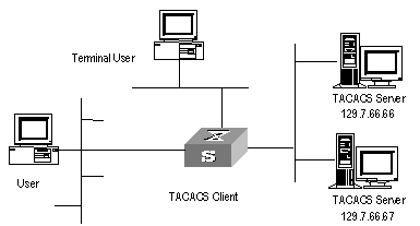
Figure 2-1 Network diagram for HWTACACS
II. Basic message exchange procedures in HWTACACS
For example, use HWTACACS to implement authentication, authorization, and accounting for a telnet user. The basic message exchange procedures are as follows:
l A user requests access to the switch; the TACACS client sends a start-authentication packet to TACACS server upon receiving the request.
l The TACACS server sends back an authentication response requesting for the username; the TACACS client asks the user for the username upon receiving the response.
l The TACACS client sends an authentication continuance packet carrying the username after receiving the username from the user.
l The TACACS server sends back an authentication response, requesting for the login password. Upon receiving the response, the TACACS client requests the user for the login password.
l After receiving the login password, the TACACS client sends an authentication continuance packet carrying the login password to the TACACS server.
l The TACACS server sends back an authentication response indicating that the user has passed the authentication.
l The TACACS client sends the user authorization packet to the TACACS server.
l The TACACS server sends back the authorization response, indicating that the user has passed the authorization.
l Upon receipt of the response indicating an authorization success, the TACACS client pushes the configuration interface of the switch to the user.
l The TACACS client sends a start-accounting request to the TACACS server.
l The TACACS server sends back an accounting response, indicating that it has received the start-accounting request.
l The user logs off; the TACACS client sends a stop-accounting request to the TACACS server.
l The TACACS server sends a stop-accounting response to the client, which indicates it has received the stop-accounting request packet.
The following figure illustrates the basic message exchange procedures:
Figure 2-2 illustrates the basic message exchange procedures.
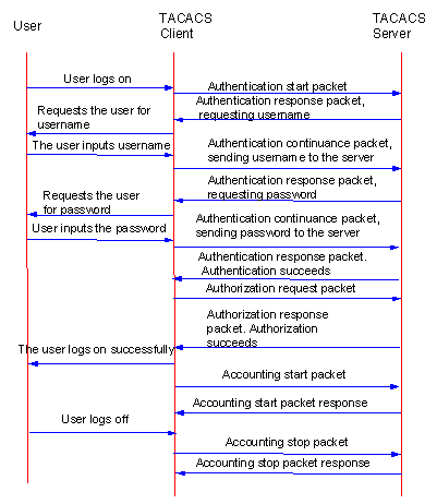
Figure 2-2 Basic message exchange procedures
2.1.4 Implementing AAA/RADIUS on a Switch
By now, we understand that in the above-mentioned AAA/RADIUS framework, H3C Series Switches, serving as the user access device (NAS), is the client end of RADIUS. In other words, the AAA/RADIUS concerning client-end is implemented on H3C Series Switches. Figure 2-3 illustrates the RADIUS authentication network including H3C Series Switches.
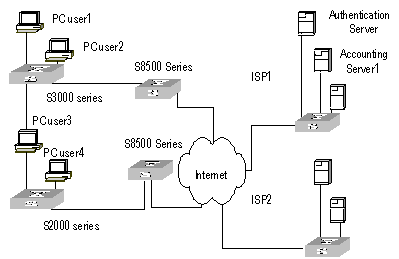
Figure 2-3 Network diagram for using RADIUS to authenticate
2.2 AAA Configuration
The following sections describe AAA configuration tasks.
l Creating/Deleting an ISP Domain
l Configuring Relevant Attributes of an ISP Domain
l Configuring Self-Service Server URL
l Creating/Deleting a Local User
l Setting the Attributes of a Local User
l Disconnecting a User by Force
l Configuring Dynamic VLAN Delivering
Among the above configuration tasks, creating ISP domain is compulsory; otherwise the supplicant attributes cannot be distinguished. The other tasks are optional. You can configure them at requirements.
2.2.1 Creating/Deleting an ISP Domain
The purpose of introducing ISP domain settings is to support the multi-ISP application environment. In such environment, one access device might access users of different ISP. Because the attributes of ISP users, such as username and password formats, etc, may be different, it is necessary to differentiate them through setting ISP domain. In H3C Series Switches ISP domain view, you can configure a complete set of exclusive ISP domain attributes on a per-ISP domain basis, which includes AAA policy (RADIUS scheme applied etc.)
For H3C Series Switches, each supplicant belongs to an ISP domain. Up to 16 domains can be configured in the system. If a user has not reported its ISP domain name, the system will put it into the default domain.
Perform the following configuration in system view.
Table 2-2 Create/Delete an ISP domain
|
Operation |
Command |
|
Create ISP domain or enter the view of a specified domain |
domain isp-name |
|
Remove a specified ISP domain |
undo domain isp-name |
|
Enable the default ISP domain specified by isp-name |
domain default enable isp-name |
|
Restore the default ISP domain to “system” |
domain default disable |
By default, a domain named “system” has been created in the system. The attributes of “system” are all default values.
2.2.2 Configuring Relevant Attributes of an ISP Domain
l The adopted RADIUS scheme is the one used by all the users in the ISP domain. The RADIUS scheme can be used for RADIUS authentication or accounting. By default, the default RADIUS scheme is used. The command shall be used together with the commands of setting RADIUS server and server cluster. For details, refer to the following Configuring RADIUS section of this chapter. If Local is configured as the first scheme, only the Local scheme will be adopted, neither RADIUS nor HWTACACS scheme will be adopted. When Local scheme is adopted, only authentication and authorization will be performed, accounting will not be performed. None has the same effect as Local. The usernames used for Local authentication carry no domain name, so if the Local scheme is configured, pay attention not to add domain name to the username when you configure a Local user.
l Every ISP domain has two states: Active and Block. If an ISP domain is in Active state, the users in it are allowed to request network services, while in Block state, its users are inhibit from requesting any network service, which will not affect the users already online. An ISP is in Active state once it is created, that is, at that time, all the users in the domain are allowed to request network services.
l Maximum number of supplicants specifies how many supplicants can be contained in the ISP. For any ISP domain, there is no limit to the number of supplicants by default.
l The idle cut function means: If the traffic from a certain connection is lower than the defined traffic, cut off this connection.
l The PPP access users can obtain IP addresses through the PPP address negotiation function.
Perform the following configuration in ISP domain view.
Table 2-3 Configure relevant attributes of an ISP domain
|
Operation |
Command |
|
Configure the AAA scheme used by an ISP domain |
scheme { radius-scheme radius-scheme-name [ local ] | hwtacacs-scheme hwtacacs-scheme-name [ local ] | local | none } |
|
Restore the default AAA scheme used by an ISP domain |
undo scheme { radius-scheme | hwtacacs-scheme | none } |
|
Configure the RADIUS scheme used by an ISP domain |
radius-scheme radius-scheme-name |
|
Delete the specified RADIUS scheme |
undo radius scheme radius-server-name |
|
Set the state of ISP domain |
state { primary | secondary } { accounting | authentication } { block | active } |
|
Set a limit to the amount of supplicants |
access-limit { disable | enable max-user-number } |
|
Restore the limit to the default setting |
undo access-limit |
|
Enable accounting to be optional |
accounting optional |
|
Disable accounting to be optional |
undo accounting optional |
|
Set the Idle-cut |
idle-cut { disable | enable minute flow } |
|
Define an address pool to assign IP addresses to users |
ip pool pool-number low-ip-address [ high-ip-address ] |
|
Delete the specified address pool |
undo ip pool pool-number |
Both the radius-scheme and scheme radius-scheme commands can be used to specify the RADIUS scheme for an ISP domain with the same effect, and the system adopts the last configuration.
By default, the Local scheme is adopted, an ISP domain is in Active state once it is created, no limit is set to the amount of supplicants, accounting optional is disabled, idle-cut is disabled, and no IP address pool is defined.
2.2.3 Configuring Self-Service Server URL
The self-service-url enable command must be incorporated with a RADIUS server (such as a CAMS server) that supports self-service. Self-service means that users can manage their accounts and card numbers by themselves. And a server with the self-service software is called a self-service server.
Once this function is enabled on the switch, users can locate the self-service server through the following operations:
l Select "Change user password" on the 802.1x client.
l After the client opens the default explorer (IE or NetScape), locate the specified URL page used to change the user password on the self-service server.
l Change user password on this page.
Perform the following configuration in ISP domain view.
Table 2-4 Configure the self-service server URL
|
Operation |
Command |
|
Configure self-service server URL and configure the URL address used to change the user password on the self-service server |
self-service-url enable url-string |
|
Remove the configuration of self-service server URL |
self-service-url disable |
By default, self-service server URL is not configured on the switch.
Note that, if "?" is contained in the URL, you must replace it with "|" when inputting the URL in the command line.
The "Change user password" option is available only when the user passes the authentication; otherwise, this option is in grey and unavailable.
2.2.4 Creating/Deleting a Local User
Perform the following configuration in system view.
Table 2-5 Create/Delete a local user
|
Operation |
Command |
|
Add a local user |
local-user { username | multicast [ domain domain-name ] ipaddress | password-display-mode { auto | cipher-force } } |
|
Delete all the local users |
undo local-user all |
|
Delete a local user by specifying its type |
undo local-user { username | all [ service-type { ftp | lan-access | telnet | ppp | ssh | terminal } ] | multicast [ domain domain-name ] ipaddress | password-display-mode } |
By default, the user database of the system is empty. If the client user wants to access the FTP Server through FTP, the configuration is required.
2.2.5 Setting the Attributes of a Local User
The attributes of a local user include its password display mode, state, service type and some other settings.
I. Setting the password display mode
Perform the following configuration in system view.
Table 2-6 Set the method that a local user uses to display password
|
Operation |
Command |
|
Set the mode that a local user uses to display password |
local-user password-display-mode { cipher-force | auto } |
|
Cancel the mode that the local user uses to display password |
undo local-user password-display-mode |
Where, auto means that the password display mode will be the one specified by the user at the time of configuring password (see the password command in the following table for reference), and cipher-force means that the password display mode of all the accessing users must be in cipher text.
II. Setting/Removing the attributes of a local user
Perform the following configuration in local user view.
Table 2-7 Set/Remove the attributes concerned with a specified user
|
Operation |
Command |
|
Set a password for a specified user |
password { simple | cipher } password |
|
Remove the password set for the specified user |
undo password |
|
Set the state of the specified user |
state { active | block } |
|
Set a service type for the specified user |
service-type { ftp [ ftp-directory directory ] | lan-access | ppp [ call-number call-number | callback-nocheck | callback-number callback-number ] | ssh [ level level | telnet | terminal ] | telnet [ level level | ssh | temninal ] | terminal [ level level | ssh | telnet ] } |
|
Cancel the service type of the specified user |
undo service-type { ftp [ ftp-directory directory ] | lan-access | ppp [call-number call-number | callback-nocheck | callback-number callback-number ] | ssh [ level level | telnet | terminal ] | telnet [ level level | ssh | terminal ] | terminal [ level level | ssh | telnet ] } |
|
Set the priority of the specified user |
level level |
|
Restore the default priority of the specified user |
undo level |
|
Configure the attributes of Lan-access users |
attribute { ip ip-address | mac mac-address | idle-cut second | access-limit max-user-number | vlan vlanid | location { nas-ip ip-address port portnum | port portnum }* |
|
Remove the attributes defined for the lan-access users |
undo attribute { ip | mac | idle-cut | access-limit | vlan | location }* |
By default, users are not authorized to any service, all their priorities are 0.
2.2.6 Disconnecting a User by Force
Sometimes it is necessary to disconnect a user or a category of users by force. The system provides the following command to serve for this purpose.
Perform the following configuration in system view.
Table 2-8 Disconnect a user by force
|
Operation |
Command |
|
Disconnect a user by force |
cut connection { all | access-type { dot1x | gcm | mac-authentication } | domain domain-name | interface interface-type interface-number | ip ip-address | mac mac-address | radius-scheme radius-scheme-name | vlan vlanid | ucibindex ucib-index | user-name user-name } |
2.2.7 Configuring Dynamic VLAN Delivering
Dynamic VLAN delivering aims to control the network resources available to a user. With this function enabled, a switch adds the ports connecting to authenticated users to specified VLANs according to the attribute values delivered by the RADIUS server. In actual use, ports are usually set to operate in port-based mode in order to work together with Guest VLAN. A port operating in MAC address-based mode can only have one host connected to it.
Currently, the VLAN IDs delivered by RADIUS servers can be of integer or string type.
l As for a VLAN ID that is of integer type, a switch adds the port to the corresponding VLAN according to the VLAN ID delivered by the RADIUS server. If the VLAN does not exist, the switch creates the VLAN first and then adds ports to the VLAN.
l As for a VLAN ID that is of string type, a switch compares the VLAN ID delivered by the RADIUS server with the names of the VLANs existing on the switch. If a matching entry is found, the switch adds the port to the corresponding VLAN. Otherwise, the delivery fails and the user fails to pass the authentication.
& Note:
l When configuring a VLAN delivering mode, keep the mode configured on the switch consistent with the mode configured on the Radius Server..
l For the string delivery mode, the value range of the VLAN name supported by the switch is 1-32 characters. If the name configured on the Radius Server exceeds 32 characters, the delivery will fail.
l For the string delivery mode, a string that contains numerals only is first interpreted as a number. That is, if the VLAN name delivered by the RADIUS server contains only numerals (such as “1024”), and the equivalent integer is within the range 1 to 4,094, the switch takes the VLAN name as an integer and add the authenticated port to the VLAN identified by the integer (In this case, the switch will add the port to VLAN 1024). If the equivalent integer is not within the range 1 to 4,094 (such as string “12345”), the RADIUS server fails to deliver the VALN name; if the all-numeral string contains space, such as “ 12 345”, the first block of non-spaced numbers in the string will be converted into its equivalent integer, namely, integer 12 in this example.
Dynamic VLAN delivering configuration includes:
l Configuring VLAN delivery mode (integer or string)
l Configuring the name of the delivered VLAN
I. Configuring VLAN delivery mode
Perform the following configuration in ISP domain view.
Table 2-9 Configure VLAN delivery mode
|
Operation |
Command |
|
Configure the VLAN delivery mode to be integer |
vlan-assignment-mode integer |
|
Configure the VLAN delivery mode to be string |
vlan-assignment-mode string |
By default, the integer mode is used. That is, the switch supports the RADIUS server delivering VLAN IDs in integer form.
II. Configuring name of a delivered VLAN
Perform the following configuration in VLAN view.
Table 2-10 Configure the name of a delivered VLAN
|
Operation |
Command |
|
Configure the name of a delivered VLAN |
name string |
|
Remove the configured VLAN name and restore it to the default name |
undo name |
By default, the delivered VLAN does not have a name.
2.3 Configuring RADIUS Protocol
For the H3C Series Switches, the RADIUS protocol is configured on the per RADIUS scheme basis. In real networking environment, a RADIUS scheme can be an independent RADIUS server or a set of primary/secondary RADIUS servers with the same configuration but two different IP addresses. Accordingly, attributes of every RADIUS scheme include IP addresses of primary and secondary servers, shared key and RADIUS server type etc.
Actually, RADIUS protocol configuration only defines some necessary parameters using for information interaction between NAS and RADIUS Server. To make these parameters take effect on an ISP domain, you must configure the ISP domain to use the RADIUS scheme configured with these parameters in ISP domain view. For more about the configuration commands, refer to the AAA Configuration section above.
The following sections describe RADIUS protocol configuration tasks.
l Creating/Deleting a RADIUS scheme
l Setting IP Address and Port Number of a RADIUS Server
l Setting the RADIUS Packet Encryption Key
l Configuring VPN of RADIUS Server
l Setting the Maximum Retry Times for RADIUS Request Packets
l Setting Quiet Time of RADIUS Server
l Enabling the Selection of Radius Accounting Option
l Setting a Real-time Accounting Interval
l Setting the Maximum Times of Real-time Accounting Request Failing to be Responded
l Enabling/Disabling Stopping Accounting Request Buffer
l Setting the Maximum Retransmitting Times of Stopping Accounting Request
l Setting the Supported Type of RADIUS Server
l Setting the Username Format Transmitted to RADIUS Server
l Setting the Unit of Data Flow that Transmitted to RADIUS Server
l Configuring a Local RADIUS Authentication Server
Among the above tasks, creating RADIUS scheme and setting IP address of RADIUS server are required, while other takes are optional and can be performed as your requirements.
2.3.1 Creating/Deleting a RADIUS scheme
As mentioned above, RADIUS protocol configurations are performed on the per RADIUS scheme basis. Therefore, before performing other RADIUS protocol configurations, it is compulsory to create the RADIUS scheme and enter its view.
You can use the following commands to create/delete a RADIUS scheme.
Perform the following configuration in system view.
Table 2-11 Create/Delete a RADIUS server group
|
Operation |
Command |
|
Create a RADIUS server group and enter its view |
radius scheme radius-server-name |
|
Delete a RADIUS server group |
undo radius scheme radius-server-name |
Several ISP domains can use a RADIUS server group at the same time. You can configure up to 16 RADIUS schemes, including the default server group named as System.
By default, the system has a RADIUS scheme named “system” whose attributes are all default values.
2.3.2 Setting IP Address and Port Number of a RADIUS Server
After creating a RADIUS scheme, you are supposed to set IP addresses and UDP port numbers for the RADIUS servers, including primary/secondary authentication/authorization servers and accounting servers. So you can configure up to 4 groups of IP addresses and UDP port numbers. However, at least you have to set one group of IP address and UDP port number for each pair of primary/secondary servers to ensure the normal AAA operation.
You can use the following commands to configure the IP address and port number for RADIUS schemes.
Perform the following configuration in RADIUS scheme view.
Table 2-12 Set IP Address and Port Number of RADIUS Server
|
Operation |
Command |
|
Set IP address and port number of primary RADIUS authentication/authorization server. |
primary authentication ip-address [ port-number ] |
|
Restore IP address and port number of primary RADIUS authentication/authorization or server to the default values. |
undo primary authentication |
|
Set IP address and port number of primary RADIUS accounting server. |
primary accounting ip-address [ port-number ] |
|
Restore IP address and port number of primary RADIUS accounting server or server to the default values. |
undo primary accounting |
|
Set IP address and port number of secondary RADIUS authentication/authorization server. |
secondary authentication ip-address [ port-number ] |
|
Restore IP address and port number of secondary RADIUS authentication/authorization or server to the default values. |
undo secondary authentication |
|
Set IP address and port number of secondary RADIUS accounting server. |
secondary accounting ip-address [ port-number ] |
|
Restore IP address and port number of secondary RADIUS accounting server or server to the default values. |
undo secondary accounting |
By default, as for the "system" RADIUS scheme created by the system:
The IP address of the primary authentication server is 127.0.0.1, and the UDP port number is 1645.
The IP address of the secondary authentication server is 0.0.0.0, and the UDP port number is 1812.
The IP address of the primary accounting server is 127.0.0.1, and the UDP port number is 1646
The IP address of the secondary accounting server is 0.0.0.0, and the UDP port number is 1813;
As for the newly created RADIUS scheme:
The IP address of the primary/secondary authentication server is 0.0.0.0, and the UDP port number of this server is 1812;
The IP address of the primary/secondary accounting server is 0.0.0.0, and the UDP port number of this server is 1813;
In real networking environments, the above parameters shall be set according to the specific requirements. For example, you may specify 4 groups of different data to map 4 RADIUS servers, or specify one of the two servers as primary authentication/authorization server and secondary accounting server and the other one as secondary authentication/authorization server and primary accounting server, or you may also set 4 groups of exactly same data so that every server serves as a primary and secondary AAA server.
To guarantee the normal interaction between NAS and RADIUS server, you are supposed to guarantee the normal routes between RADIUS/HWTACACS server and NAS before setting IP address and UDP port of the RADIUS server and IP address and TCP port of the HWTACACS server. In addition, because RADIUS/HWTACACS protocol uses different ports to receive/transmit authentication/authorization and accounting packets, you shall set two different ports accordingly. Suggested by RFC2138/2139, authentication/authorization port number is 1812 and accounting port number is 1813. However, you may use values other than the suggested ones. (Especially for some earlier RADIUS/HWTACACS Servers, authentication/authorization port number is often set to 1645 and accounting port number is 1646.)
The RADIUS/HWTACACS service port settings on H3C Series Switches are supposed to be consistent with the port settings on RADIUS server. Normally, RADIUS accounting service port is 1813 and the authentication/authorization service port is 1812.
& Note:
For a S9500 series routing switch, the default RADIUS scheme authentication/authorization port is 1645, the accounting port is 1646. And port 1812 and 1813 are for other schemes.
2.3.3 Setting the RADIUS Packet Encryption Key
RADIUS client (switch system) and RADIUS server use MD5 algorithm to encrypt the exchanged packets. The two ends verify the packet through setting the encryption key. Only when the keys are identical can both ends to accept the packets from each other end and give response.
You can use the following commands to set the encryption key for RADIUS packets.
Perform the following configuration in RADIUS scheme view.
Table 2-13 Set RADIUS packet encryption key
|
Operation |
Command |
|
Set RADIUS authentication/authorization packet encryption key |
key authentication string |
|
Restore the default RADIUS authentication/authorization packet encryption key |
undo key authentication |
|
Set RADIUS accounting packet encryption key |
key accounting string |
|
Restore the default RADIUS accounting packet encryption key |
undo key accounting |
By default, the encryption keys of RADIUS authentication/authorization and accounting packets are null.
2.3.4 Configuring VPN of RADIUS Server
Use the following commands to configure the VPN of the RADIUS Server.
Perform the following configuration in RADIUS scheme view.
Table 2-14 Configure the VPN of the RADIUS Server
|
Operation |
Command |
|
Set the VPN that the RADIUS Server belongs to |
vpn-instance vpn-name |
|
Restore the VPN attribute of RADIUS Server to the default value |
undo vpn-instance |
The RADIUS Server does not belong to any VPN by default.
2.3.5 Setting the Maximum Retry Times for RADIUS Request Packets
Because RADIUS Protocol carries data through UDP packets, its communication process is not reliable. If the RADIUS Server does not respond to the NAS within the time specified by the response timeout timer, it is necessary for the NAS to retry sending the RADIUS request packets to the RADIUS Server. If the number of retry times exceeds maximum retry times while the RADIUS Server still does not respond, the NAS will assume its communication with the current RADIUS Server to have been cut off and will send request packets to another RADIUS Server.
Use the following commands to set the maximum retry times of sending RADIUS request packets.
Perform the following configuration in RADIUS scheme view.
Table 2-15 Set the maximum retry times of sending RADIUS request packets
|
Operation |
Command |
|
Set the maximum retry times of sending RADIUS request packets |
retry retry-times |
|
Restore the maximum retry times of sending RADIUS request packets to the default value |
undo retry |
By default, the maximum retry times of sending RADIUS request packets is 3.
2.3.6 Setting RADIUS Server Response Timeout Timer
If the NAS fails to receive the response from RADIUS server a certain period of time after it sends a RADIUS request packet (authentication/authorization request or accounting request), it should retransmit the RADIUS request packet to ensure the RADIUS service for the user.
You can use the following command to set the response timeout timer of the RADIUS server.
Perform the following configuration in RADIUS scheme view.
Table 2-16 Set RADIUS server response timeout timer
|
Operation |
Command |
|
Set the response timeout timer of RADIUS server |
timer response-timeout seconds |
|
Restore the default value of the response timeout timer of RADIUS server |
undo timer response-timeout |
The default value of the response timeout timer of a RADIUS server is 3 seconds.
2.3.7 Setting Quiet Time of RADIUS Server
When the communication between the switch and the RADIUS Server is interrupted, the switch will stop processing request packets from the users, and will send user request packets to the RADIUS Server after it has waited for a certain period of time.
Use the following command to set the quiet time of the RADIUS Server.
Perform the following configuration in RADIUS scheme view.
Table 2-17 Set quiet time of RADIUS Server
|
Operation |
Command |
|
Set quiet time of RADIUS Server |
timer quiet minutes |
|
Restore quiet time of RADIUS Server to the default value |
undo timer quiet |
By default, the quiet time of the primary server is 5 minutes.
2.3.8 Enabling the Selection of Radius Accounting Option
Perform the following configuration in RADIUS scheme view.
Table 2-18 Enable the selection of RADIUS accounting option
|
Operation |
Command |
|
Enable the selection of RADIUS accounting option |
accounting optional |
|
Disable the selection of RADIUS accounting option |
undo accounting optional |
By default, selection of RADIUS accounting option is disabled.
2.3.9 Setting a Real-time Accounting Interval
To implement real-time accounting, it is necessary to set a real-time accounting interval. After the attribute is set, NAS will transmit the accounting information of online users to the RADIUS server regularly.
You can use the following command to set a real-time accounting interval.
Perform the following configuration in RADIUS scheme view.
Table 2-19 Set a real-time accounting interval
|
Operation |
Command |
|
Set a real-time accounting interval |
timer realtime-accounting minute |
|
Restore the default value of the interval |
undo timer realtime-accounting |
minute specifies the real-time accounting interval in minutes. The value shall be a multiple of 3.
The value of minute is related to the performance of NAS and RADIUS server. The smaller the value is, the higher the performances of NAS and RADIUS are required. When there are a large amount of users (more than 1000, inclusive), we suggest a larger value. The following table recommends the ratio of minute value to the number of users.
Table 2-20 Recommended real-time accounting intervals for different number of users
|
Number of users |
Real-time accounting interval in minutes |
|
1 to 99 |
3 |
|
100 to 499 |
6 |
|
500 to 999 |
12 |
|
≥1000 |
≥15 |
By default, minute is set to 12 minutes.
2.3.10 Setting the Maximum Times of Real-time Accounting Request Failing to be Responded
RADIUS server usually checks if a user is online with timeout timer. If the RADIUS server has not received the real-time accounting packet from NAS for long, it will consider that there is device failure and stop accounting. Accordingly, it is necessary to disconnect the user at NAS end and on RADIUS server synchronously when some unpredictable failure exists. H3C Series Switches support to set maximum times of real-time accounting request failing to be responded. NAS will disconnect the user if it has not received real-time accounting response from RADIUS server for some specified times.
You can use the following command to set the maximum times of real-time accounting request failing to be responded.
Perform the following configuration in RADIUS scheme view.
Table 2-21 Set the maximum times of real-time accounting request failing to be responded
|
Operation |
Command |
|
Set maximum times of real-time accounting request failing to be responded |
retry realtime-accounting retry-times |
|
Restore the maximum times to the default value |
undo retry realtime-accounting |
How to calculate the value of retry-times? Suppose that RADIUS server connection will timeout in T and the real-time accounting interval of NAS is t, then the integer part of the result from dividing T by t is the value of count. Therefore, when applied, T is suggested the numbers which can be divided exactly by t.
By default, the real-time accounting request can fail to be responded no more than 5 times.
2.3.11 Enabling/Disabling Stopping Accounting Request Buffer
Because the stopping accounting request concerns account balance and will affect the amount of charge, which is very important for both the subscribers and the ISP, NAS shall make its best effort to send the request to RADIUS accounting server. Accordingly, if the request from H3C Series Switches to RADIUS accounting server has not been responded, switch shall save it in the local buffer and retransmit it until the server responds or discards the messages after transmitting for specified times. You can use the following command to set whether or not to save the stopping accounting requests.
Perform the following configuration in RADIUS scheme view.
Table 2-22 Enable/Disable stopping accounting request buffer
|
Operation |
Command |
|
Enable stopping accounting request buffer |
stop-accounting-buffer enable |
|
Disable stopping accounting request buffer |
undo stop-accounting-buffer enable |
By default, the stopping accounting request will be saved in the buffer.
2.3.12 Setting the Maximum Retransmitting Times of Stopping Accounting Request
Because the stopping accounting request concerns account balance and will affect the amount of charge, which is very important for both the subscribers and the ISP, NAS shall make its best effort to send the message to RADIUS accounting server. Accordingly, if the request from H3C Series Switch to RADIUS accounting server has not been responded, switch shall save it in the local buffer and retransmit it until the server responds or discards the messages after transmitting for specified times. Use the following command to set the maximum retransmission times.
Perform the following configuration in RADIUS scheme view.
Table 2-23 Set the maximum retransmitting times of stopping accounting request
|
Operation |
Command |
|
Set the maximum retransmitting times of stopping accounting request |
retry stop-accounting retry-times |
|
Restore the maximum retransmitting times of stopping accounting request to the default value |
undo retry stop-accounting |
By default, the stopping accounting request can be retransmitted for up to 500 times.
2.3.13 Setting the Supported Type of RADIUS Server
H3C Series Switches support the standard RADIUS protocol and the extended RADIUS service platforms, such as IP Hotel, 201+ and Portal, independently developed by H3C.
You can use the following command to set the supported types of RADIUS servers.
Perform the following configuration in RADIUS scheme view.
Table 2-24 Set the supported type of RADIUS scheme
|
Operation |
Command |
|
Set the Supported Type of RADIUS Server |
server-type { extended | standard } |
|
Restore the Supported Type of RADIUS Server to the default setting |
undo server-type |
By default, the newly created RADIUS scheme supports the server of standard type, while the "system" RADIUS scheme created by the system supports the server of extended type
2.3.14 Setting RADIUS Server State
For the primary and secondary servers (no matter it is an authentication/authorization server or accounting server), if the primary is disconnected to NAS for some fault, NAS will automatically turn to exchange packets with the secondary server. However, after the primary one recovers, NAS will not resume the communication with it at once, instead, it continues communicating with the secondary one. When the secondary one fails to communicate, NAS will turn to the primary one again. The following commands can be used to set the primary server to be active manually, in order that NAS can communicate with it right after the troubleshooting.
When the primary and secondary servers are both active or block, NAS will send the packets to the primary server only.
Perform the following configuration in RADIUS scheme view.
Table 2-25 Set RADIUS server state
|
Operation |
Command |
|
Set the state of the primary RADIUS authentication/authorization server |
state primary authentication { block | active } |
|
Set the state of the primary RADIUS accounting server |
state primary accounting { block | active } |
|
Set the state of the secondary RADIUS authentication/authorization server |
state secondary authentication { block | active } |
|
Set the state of the secondary RADIUS accounting server |
state secondary accounting { block | active } |
By default, the state of each server in RADIUS scheme server group is active.
2.3.15 Setting the Username Format Transmitted to RADIUS Server
Perform the following configuration in RADIUS scheme view.
Table 2-26 Set the username format transmitted to RADIUS server
|
Operation |
Command |
|
Set Username Format Transmitted to RADIUS Server |
user-name-format { with-domain | without-domain } |
& Note:
If a RADIUS scheme is configured not to allow usernames including ISP domain names, the RADIUS scheme shall not be simultaneously used in more than one ISP domain. Otherwise, the RADIUS server will regard two users in different ISP domains as the same user by mistake, if they have the same username (excluding their respective domain names.)
By default, as for the newly created RADIUS scheme, the username sent to RADIUS servers includes an ISP domain name; as for the "system" RADIUS scheme created by the system, the username sent to RADIUS servers excludes the ISP domain name.
2.3.16 Setting the Unit of Data Flow that Transmitted to RADIUS Server
The following command defines the unit of the data flow sent to RADIUS server.
Perform the following configuration in RADIUS scheme view.
Table 2-27 Set the unit of data flow transmitted to RADIUS server
|
Operation |
Command |
|
Set the unit of data flow transmitted to RADIUS server |
data-flow-format { data { byte | giga-byte | kilo-byte | mega-byte } } | { packet { giga-byte | kilo-byte | mega-byte | one-packet } } |
|
Restore the unit to the default setting |
undo data-flow-format |
By default, the default data unit is byte and the default data packet unit is one packet.
2.3.17 Configuring the Source Address Used by NAS in RADIUS Packets
Perform the following configuration in the corresponding view.
Table 2-28 Configuring the source address used by the NAS in RADIUS packets
|
Operation |
Command |
|
Configure the source address used by the NAS in RADIUS packets (RADIUS scheme view) |
nas-ip ip-address |
|
Cancel the configured source address used by the NAS in RADIUS packets (RADIUS scheme view) |
undo nas-ip |
|
Configure the source address used by the NAS in RADIUS packets (System view) |
radius nas-ip ip-address [ vpn-instance vpn-instance-name ] |
|
Cancel the configured source address used by the NAS in RADIUS packets (System view) |
undo radius nas-ip [ vpn-instance vpn-instance-name ] |
The effect of the two commands is the same. However, the configuration done in RADIUS scheme view has a higher priority than the configuration done in system view.
By default, no source address is specified, that is to say, the interface from which a packet is sent is regarded as the source address of the packet.
2.3.18 Configuring a Local RADIUS Authentication Server
Perform the following configuration in system view.
Table 2-29 Create/Delete a local RADIUS authentication server
|
Operation |
Command |
|
Create a local RADIUS authentication server |
local-server nas-ip ip-address key password |
|
Delete a local RADIUS authentication server |
undo local-server nas-ip ip-address |
By default, the IP address of local RADIUS authentication server group is 127.0.0.1 and the password is null.
When using local RADIUS server function, note that,
1) The number of UDP port used for authentication/authorization is 1645 and that for accounting is 1646.
2) The password configured by local-server command must be the same as that of the RADIUS authentication/authorization packet configured by the command key authentication in radius scheme view.
3) S9500 series serving as local RADIUS authentication servers currently only support the CHAP and PAP authentication modes; they do not support the MD5-challenge mode.
2.4 Configuring HWTACACS Protocol
The following sections describe HWTACACS configuration tasks.
l Configuring HWTACACS Authentication Servers
l Configuring HWTACACS Authorization Servers
l Configuring HWTACACS Accounting Servers and the Related Attributes
l Configuring the Source Address for HWTACACS Packets Sent by NAS
l Setting a Key for Securing the Communication with TACACS Server
l Setting the Username Format Acceptable to the TACACS Server
l Setting the Unit of Data Flows Destined for the TACACS Server
l Setting Timers Regarding TACACS Server
& Note:
Pay attention to the following when configuring a TACACS server:
l HWTACACS server does not check whether a scheme is being used by users when changing most of HWTACS attributes, unless you delete the scheme.
l By default, the TACACS server has no key.
In the above configuration tasks, creating HWTACACS scheme and configuring TACACS authentication/authorization server are required; all other tasks are optional and you can determine whether to perform these configurations as needed.
2.4.1 Creating a HWTACAS Scheme
As aforementioned, HWTACACS protocol is configured scheme by scheme. Therefore, you must create a HWTACACS scheme and enter HWTACACS view before you perform other configuration tasks.
Perform the following configuration in system view.
Table 2-30 Create a HWTACACS scheme
|
Operation |
Command |
|
Create a HWTACACS scheme and enter HWTACACS view |
hwtacacs scheme hwtacacs-scheme-name |
|
Delete a HWTACACS scheme |
undo hwtacacs scheme hwtacacs-scheme-name |
By default, no HWTACACS scheme exists.
If the HWTACACS scheme you specify does not exist, the system creates it and enters HWTACACS view. In HWTACACS view, you can configure the HWTACACS scheme specifically.
The system supports up to 16 HWTACACS schemes. You can only delete the schemes that are not being used.
2.4.2 Configuring HWTACACS Authentication Servers
Perform the following configuration in HWTACACS view.
Table 2-31 Configure HWTACACS authentication servers
|
Operation |
Command |
|
Configure the HWTACACS primary authentication server |
primary authentication ip-address [ port-number ] |
|
Delete the HWTACACS primary authentication server |
undo primary authentication |
|
Configure the HWTACACS secondary authentication server |
secondary authentication ip-address [ port-number ] |
|
Delete the HWTACACS secondary authentication server |
undo secondary authentication |
The primary and secondary authentication servers cannot use the same IP address. The default port number is 49.
If you execute this command repeatedly, the new settings will replace the old settings.
A TACACS scheme authentication server can be deleted only when no Active TCP connection used to send authentication packets is using the server.
2.4.3 Configuring HWTACACS Authorization Servers
Perform the following configuration in HWTACACS view.
Table 2-32 Configure HWTACACS authorization servers
|
Operation |
Command |
|
Configure the primary HWTACACS authorization server |
primary authorization ip-address [ port-number ] |
|
Delete the primary HWTACACS authorization server |
undo primary authorization |
|
Configure the secondary HWTACACS authorization server |
secondary authorization ip-address [ port-number ] |
|
Delete the secondary HWTACACS authorization server |
undo secondary authorization |
& Note:
If only authentication and accounting servers are configured and no authorization server is configured, both authentication and accounting can be performed normally for the FTP, Telnet, and SSH users, but the priority of these users is 0 (that is, the lowest privilege level) by default,
The primary and secondary authorization servers cannot use the same IP address. The default port number is 49.
If you execute this command repeatedly, the new settings will replace the old settings.
2.4.4 Configuring HWTACACS Accounting Servers and the Related Attributes
I. Configuring HWTACACS accounting servers
Perform the following configuration in HWTACACS view.
Table 2-33 Configure HWTACACS accounting servers
|
Operation |
Command |
|
Configure the primary TACACS accounting server |
primary accounting ip-address [ port-number ] |
|
Delete the primary TACACS accounting server |
undo primary accounting |
|
Configure the secondary TACACS accounting server |
secondary accounting ip-address [ port-number ] |
|
Delete the secondary TACACS accounting server |
undo secondary accounting |
Do not configure the same IP address for the primary accounting server and the secondary accounting server. Otherwise, an error occurs.
By default, a TACACS accounting server uses an all-zero IP address and port 49.
If you execute the primary accounting or secondary accounting command repeatedly, the newly configured settings overwrite the corresponding existing settings.
You can delete a TACACS scheme only when no Active TCP connection used to send authentication packets uses the server.
II. Enabling stop-accounting packet retransmission
Perform the following configuration in HWTACACS view.
Table 2-34 Configure stop-accounting packet retransmission
|
Operation |
Command |
|
Enable stop-accounting packet retransmission and set the allowed maximum number of transmission attempts |
retry stop-accounting retry-times |
|
Disable stop-accounting packet retransmission |
undo retry stop-accounting |
|
Clear the stop-accounting request packets that have no response |
reset stop-accounting-buffer hwtacacs-scheme hwtacacs-scheme-name |
By default, stop-accounting packet retransmission is enabled, and the maximum number of transmission attempts is 300.
2.4.5 Configuring the Source Address for HWTACACS Packets Sent by NAS
Perform the following configuration in the corresponding view.
Table 2-35 Configure the source address for HWTACACS packets sent by the NAS
|
Operation |
Command |
|
Configure the source address for HWTACACS packets sent from the NAS (HWTACACS view) |
nas-ip ip-address |
|
Delete the configured source address for HWTACACS packets sent from the NAS (HWTACACS view) |
undo nas-ip |
|
Configure the source address for HWTACACS packets sent from the NAS (System view) |
hwtacacs nas-ip ip-address |
|
Cancel the configured source address for HWTACACS packets sent from the NAS (System view) |
undo hwtacacs nas-ip |
The HWTACACS view takes precedence over the system view when configuring the source address for HWTACACS packets sent from the NAS.
By default, the source address is not specified, and the virtual interface of the VLAN that contains the port to which the server connects for packet sending is used as the source address.
2.4.6 Setting a Key for Securing the Communication with TACACS Server
When using a TACACS server as an AAA server, you can set a key to improve the communication security between the switch and the TACACS server.
Perform the following configuration in HWTACACS view.
Table 2-36 Set a key for securing the communication with the HWTACACS server
|
Operation |
Command |
|
Configure a key for securing the communication with the accounting, authorization or authentication server |
key { accounting | authorization | authentication } string |
|
Delete the configuration |
undo key { accounting | authorization | authentication } |
No key is configured by default.
2.4.7 Setting the Username Format Acceptable to the TACACS Server
Username is usually in the “userid@isp-name” format, with the domain name following “@”.
If a TACACS server does not accept the username with domain name, you can remove the domain name and resend it to the TACACS server.
Perform the following configuration in HWTACACS view.
Table 2-37 Set the username format acceptable to the TACACS server
|
Operation |
Command |
|
Send username with domain name |
user-name-format with-domain |
|
Send username without domain name |
user-name-format without-domain |
By default, each username sent to a TACACS server contains a domain name.
2.4.8 Setting the Unit of Data Flows Destined for the TACACS Server
Perform the following configuration in HWTACACS view.
Table 2-38 Set the unit of data flows destined for the TACACS server
|
Operation |
Command |
|
Set the unit of data flows destined for the TACACS server |
data-flow-format data { byte | giga-byte | kilo-byte | mega-byte } data-flow-format packet { giga-packet | kilo-packet | mega-packet | one-packet } |
|
Restore the default unit of data flows destined for the TACACS server |
undo data-flow-format { data | packet } |
The default data flow unit is byte.
2.4.9 Setting Timers Regarding TACACS Server
I. Setting the response timeout timer
Since HWTACACS is implemented on the basis of TCP, server response timeout or TCP timeout may terminate the connection to the TACACS server.
Perform the following configuration in HWTACACS view.
Table 2-39 Set the response timeout timer
|
Operation |
Command |
|
Set the response timeout time |
timer response-timeout seconds |
|
Restore the default setting |
undo timer response-timeout |
The default response timeout timer is set to 5 seconds.
II. Setting the quiet timer for the primary TACACS server
Perform the following configuration in HWTACACS view.
Table 2-40 Set the quiet timer for the primary TACACS server
|
Operation |
Command |
|
Set the quiet timer for the primary TACACS server |
timer quiet minutes |
|
Restore the default setting |
undo timer quiet |
The timer quiet command is used to make the switch ignore users' requests for server within the time configured in this command in case the communication between the switch and the server is terminated. In that case, the switch can send users' requests to the server only after it has waited a time no less than the time configured with this command for the communication to be resumed.
By default, the primary TACACS server must wait five minutes before it can resume the active state. The time ranges from 1 to 255.
III. Setting a realtime accounting interval
The setting of real-time accounting interval is necessary to real-time accounting. After an interval value is set, the NAS transmits the accounting information of online users to the TACACS accounting server periodically.
Perform the following configuration in HWTACACS view.
Table 2-41 Set a real-time accounting interval
|
Operation |
Command |
|
Set a real-time accounting interval |
timer realtime-accounting minute |
|
Restore the default real-time accounting interval |
undo timer realtime-accounting |
The interval is in minutes and must be a multiple of 3.
The setting of real-time accounting interval somewhat depends on the performance of the NAS and the TACACS server: a shorter interval requires higher device performance. You are therefore recommended to adopt a longer interval when there are a large number of users (more than 1000, inclusive). The following table lists the numbers of users and the recommended intervals.
Table 2-42 Numbers of users and the recommended intervals
|
Number of users |
Real-time accounting interval (in minutes) |
|
1 to 99 |
3 |
|
100 to 499 |
6 |
|
500 to 999 |
12 |
|
¦1000 |
¦15 |
The real-time accounting interval defaults to 12 minutes.
2.5 Displaying and Debugging AAA and RADIUS Protocol
Table 2-43 Display and debug AAA and RADIUS/HWTACACS protocol
|
Operation |
Command |
|
Display the configuration information of the specified or all the ISP domains |
display domain [ isp-name ] |
|
Display related information of user’s connection |
display connection { access-type { dot1x | gcm } | domain isp-name | interface interface-type interface-number | ip ip-address | mac mac-address | radius-scheme radius-scheme-name | vlan vlanid | ucibindex ucib-index | user-name user-name } |
|
Display related information of the local user |
display local-user [ domain isp-name | idle-cut { disable | enable } | service-type { ftp | lan-access | ppp | ssh | telnet | terminal } | state { active | block } | user-name user-name | vlan vlanid ] |
|
Display the statistics of local RADIUS server group |
display local-server { statistics | nas-ip } |
|
Display the configuration information of all the RADIUS server groups or a specified one |
display radius [ radius-server-name ] |
|
Display all global NAS-IP information configured in system view |
display radius nas-ip |
|
Display the statistics of RADIUS packets |
display radius statistics |
|
Display the stop-accounting requests saved in buffer without response |
display stop-accounting-buffer { radius-scheme radius-scheme-name | session-id session-id | time-range start-time stop-time | user-name user-name } |
|
Reset the statistics of RADIUS server |
reset radius statistics |
|
Display the specified or all the HWTACACS schemes |
display hwtacacs [ hwtacacs-server-name ] |
|
Display the HWTACACS stop-accounting requests saved in buffer without response |
display stop-accounting-buffer hwtacacs-scheme hwtacacs-scheme-name |
|
Delete the stop-accounting requests saved in buffer without response |
reset stop-accounting-buffer { radius-scheme radius-scheme-name | session-id session-id | time-range start-time stop-time | user-name user-name } |
|
Delete the HWTACACS stop-accounting requests saved in buffer without response |
reset stop-accounting-buffer hwtacacs-scheme hwtacacs-scheme-name |
|
Reset the statistics of HWTACACS server |
reset hwtacacs statistics { accounting | authentication | authorization | all } |
|
Enable RADIUS packet debugging |
debugging radius packet |
|
Disable RADIUS packet debugging |
undo debugging radius packet |
|
Enable debugging of local RADIUS authentication server |
debugging local-server { all | error | event | packet } |
|
Disable debugging of local RADIUS authentication server |
undo debugging local-server { all | error | event | packet } |
|
Enable HWTACACS debugging |
debugging hwtacacs { all | error | event | message | receive-packet | send-packet } |
|
Disable HWTACACS debugging |
undo debugging hwtacacs { all | error | event | message | receive-packet | send-packet } |
2.6 AAA and RADIUS/HWTACACS Protocol Configuration Examples
For the hybrid configuration example of AAA/RADIUS/HWTACACS protocol and 802.1x protocol, refer to “Packet Attack Prevention Configuration” in Chapter 1 “802.1x Configuration”.
2.6.1 Configuring Authentication at Remote RADIUS Server
& Note:
Configuring Telnet user authentication at the remote server is similar to configuring FTP users. The following description is based on Telnet users.
I. Network Requirements
In the environment as illustrated in the following figure, it is required to achieve through proper configuration that the RADIUS server authenticates the Telnet users to be registered.
One RADIUS server (as authentication server) is connected to the switch and the server IP address is 10.110.91.146. The password for exchanging messages between the switch and the authentication server is "expert”. The switch cuts off domain name from username and sends the left part to the RADIUS server.
II. Network Topology
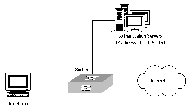
Figure 2-4 Network diagram for the remote RADIUS authentication of Telnet users
III. Configuration procedure
# Add a Telnet user.
Omitted
& Note:
For details about configuring FTP and Telnet users, refer to User Interface Configuration of Getting Started Operation part in S9500 Series Routing Switches Operation Manual.
# Configure remote authentication mode for the Telnet user, i.e. Scheme mode.
[H3C-ui-vty0-4] authentication-mode scheme
# Configure domain.
[H3C] domain cams
[H3C-isp-cams] quit
# Configure RADIUS scheme.
[H3C] radius scheme cams
[H3C-radius-cams] primary authentication 10.110.91.146 1812
[H3C-radius-cams] key authentication expert
[H3C-radius-cams] server-type extended
[H3C-radius-cams] user-name-format without-domain
# Associate the domain with RADIUS.
[H3C-radius-cams] quit
[H3C] domain cams
[H3C-isp-cams] radius-scheme cams
2.6.2 Configuring Authentication at Local RADIUS Authentication Server
Local RADIUS authentication of Telnet/FTP users is similar to the remote RADIUS authentication described in section 2.6.1 . But you should modify the server IP address in Figure 2-4 of section 2.6.1 to 127.0.0.1, authentication password to null, the UDP port number of the authentication server to 1645.
& Note:
For details about local RADIUS authentication of Telnet/FTP users, refer to “2.3.18 Configuring a Local RADIUS Authentication Server”.
2.6.3 Configuring Authentication at Remote TACACS Server
I. Network requirements
Configure the switch to use a TACACS server to provide authentication and authorization services to login users (see the following figure).
Connect the switch to one TACACS server (which acting as a AAA server) with the IP address 10.110.91.164. On the switch, set the shared key for AAA packet encryption to “expert”. Configure the switch to send usernames to the TACACS server with isp-name removed.
On the TACACS server, set the shared key for encrypting the packets exchanged with the switch to “expert” .
II. Network diagram
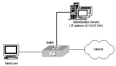
Figure 2-5 Network diagram for TACACS authentication
III. Configuration procedure
# Configure the Telnet user.
Here it is omitted.
& Note:
The configuration of the FTP and Telnet users can refer to User Interface Configuration of Getting Started Operation part in S9500 Series Routing Switches Operation Manual.
# Configure a HWTACACS scheme.
[H3C] hwtacacs scheme hwtac
[H3C-hwtacacs-hwtac] primary authentication 10.110.91.164
[H3C-hwtacacs-hwtac] primary authorization 10.110.91.164
[H3C-hwtacacs-hwtac] key authentication expert
[H3C-hwtacacs-hwtac] key authorization expert
[H3C-hwtacacs-hwtac] user-name-format without-domain
[H3C-hwtacacs-hwtac] quit
# Associate the Domain with the HWTACACS scheme.
[H3C] domain hwtacacs
[H3C-isp-hwtacacs] scheme hwtacacs-scheme hwtac
2.7 Troubleshooting AAA and RADIUS/HWTACACS
RADIUS/HWTACACS protocol is located on the application layer of TCP/IP protocol suite. It mainly specifies how to exchange user information between NAS and RADIUS/HWTACACS server of ISP. So it is very likely to be invalid.
I. Symptom: User authentication/authorization always fails
Solution:
l The username may not be in the userid@isp-name format or NAS has not been configured with a default ISP domain. Please use the username in proper format and configure the default ISP domain on NAS.
l The user may have not been configured in the RADIUS/HWTACACS server database. Check the database and make sure that the configuration information of the user does exist in the database.
l The user may have input a wrong password. So please make sure that the supplicant inputs the correct password.
l The encryption keys of RADIUS/HWTACACS server and NAS may be different. Please check carefully and make sure that they are identical.
l There might be some communication fault between NAS and RADIUS/HWTACACS server, which can be discovered through pinging RADIUS/HWTACACS server from NAS. So please ensure the normal communication between NAS and RADIUS/HWTACACS server.
II. Symptom: RADIUS/HWTACACS packet cannot be transmitted to RADIUS/HWTACACS server.
Solution:
l The communication lines (on physical layer or link layer) connecting NAS and RADIUS/HWTACACS server may not work well. So please ensure the lines work well.
l The IP address of the corresponding RADIUS/HWTACACS server may not have been set on NAS. Please set a proper IP address for RADIUS/HWTACACS server.
l Ports of authentication/authorization and accounting services may not be set properly. So make sure they are consistent with the ports provided by RADIUS/HWTACACS server.
III. Symptom: After being authenticated and authorized, the user cannot send charging bill to the RADIUS/HWTACACS server.
Solution:
l The accounting port number may be set improperly. Please set a proper number.
l The accounting service and authentication/authorization service are provided on different servers, but NAS requires the services to be provided on one server (by specifying the same IP address). So please make sure the settings of servers are consistent with the actual conditions.