- Table of Contents
-
- H3C S9500 Series Routing Switches Operation Manual-(V1.01)
- 00-1Cover
- 01-Getting Started Operation
- 02-Port Operation
- 03-VLAN-QinQ Operation
- 04-Network Protocol Operation
- 05-Routing Protocol Operation
- 06-Multicast Protocol Operation
- 07-QACL Operation
- 08-MPLS Operation
- 09-STP Operation
- 10-Security Operation
- 11-Reliability Operation
- 12-System Management Operation
- 13-PoE Operation
- 14-NAT-URPF-VPLS Operation
- 15-Integrated Management Operation
- 16-Appendix
- Related Documents
-
| Title | Size | Download |
|---|---|---|
| 04-Network Protocol Operation | 381 KB |
Table of Contents
Chapter 1 IP Address Configuration
1.1 Introduction to IP Addresses
1.1.1 IP Address Classification and Representation
1.2.1 Configuring the Hostname and Host IP Address
1.2.2 Configuring the IP Address of the VLAN Interface
1.2.3 IP Address Protection Configuration
1.4 IP Address Configuration Example
1.5 Troubleshooting IP Address Configuration
2.2.1 Manually Adding/Deleting Static ARP Mapping Entries
2.2.2 Configuring the Dynamic ARP Aging Timer
2.2.3 Adding/Deleting Multicast ARP Ports
2.2.5 Gratuitous ARP Learning Configuration
2.3 Displaying and Debugging ARP
Chapter 3 ARP Table Size Configuration
3.1 Introduction to ARP Table Size Configuration
3.2 Dynamic Configuration of the Number of ARP Entries
3.2.1 Configuration Task Overview
3.2.2 Configuring the Number of ARP Entries Dynamically
3.3 Displaying ARP Table Size Configuration
4.1.2 DHCP and BOOTP Relay Agent
4.2.1 Enabling/Disabling DHCP Service
4.2.2 Configuring Processing Method of DHCP Packets
4.2.3 Enabling/Disabling Fake DHCP Server Detection
4.3.1 Creating a Global DHCP IP Address Pool
4.3.2 Configuring IP Address Assignment Mode
4.3.3 Forbidding Specified IP Addresses to Be Automatically Assigned
4.3.4 Configuring Lease Time For DHCP Address Pool
4.3.5 Configuring DHCP Client Domain Names
4.3.6 Configuring DNS Server Address for DHCP Clients
4.3.7 Configuring NetBIOS Server Address for DHCP Clients
4.3.8 Configuring NetBIOS Node Type for DHCP Clients
4.3.9 Configuring Custom DHCP Options
4.3.10 Configuring Outbound Gateway Address for DHCP Clients
4.3.11 Configuring Parameters for DHCP Server to Send Ping Packets
4.3.12 Displaying and Debugging the DHCP Server
4.3.13 Clearing the Configuration Information of the DHCP Server
4.3.14 DHCP Server Configuration Example
4.4.1 Introduction to DHCP Relay
4.4.3 Displaying and Debugging DHCP Relay
4.4.4 DHCP Relay Configuration Example
Chapter 5 DHCP Option 82 Configuration
5.1.1 Introduction to Option 82 Support on DHCP Relay
5.1.4 Related Protocols and Specifications
5.1.5 Working Mechanism of Option 82 Support on DHCP Relay
5.2 Configuring Option 82 Supply on DHCP Relay
5.2.2 Enabling Option 82 Support on DHCP Relay
5.3.1 Option 82 Support on DHCP Relay Configuration Example
6.1.1 Static Domain Name Resolution
6.1.2 Dynamic Domain Name Resolution
6.2 Configuring Static Domain Name Resolution
6.3 Configuring Dynamic Domain Name Resolution
6.3.1 Enable/Disable Static Domain Name Resolution
6.3.2 Configure the IP Address of Domain Name Server
6.3.3 Configure Domain Name Suffix
6.4 Displaying and Debugging Domain Name Resolution
6.6 Troubleshooting Domain Name Resolution Configuration
Chapter 7 IP Performance Configuration
7.1 Configuring IP Performance
7.1.1 Configuring TCP Attributes
7.2 Displaying and Debugging IP Performance
7.3 Troubleshooting IP Performance
Chapter 1 IP Address Configuration
1.1 Introduction to IP Addresses
1.1.1 IP Address Classification and Representation
An IP address is a 32-bit address allocated to a device that accesses the Internet. It consists of two fields: net-id field and host-id field. IP addresses are allocated by Network Information Center (NIC) of American Defense Data Network (DDN). To manage IP addresses conveniently, IP addresses are classified into five types. See the following figure.

Figure 1-1 Five classes of IP addresses
Here, Class A, Class B and Class C addresses are unicast addresses, while Class D addresses are multicast ones and class E addresses are reserved for special applications in future. The first three types are commonly used.
The IP address is in dotted decimal format. Each IP address contains four integers in dotted decimal notation. Each integer corresponds to one byte, for example, 10.110.50.101.
When using IP addresses, note that some of them are reserved for special uses, and are seldom used. The IP addresses you can use are listed in the following table.
Table 1-1 IP address classes and ranges
|
Network class |
Address range |
IP network range available |
Note |
|
A |
0.0.0.0 to 127.255.255.255 |
1.0.0.0 to 126.0.0.0 |
Host ID with all the digits being 0 indicates that the IP address is the network address, and is used for network routing. Host ID with all the digits being 1 indicates the broadcast address, that is, broadcast to all hosts on the network. IP address 0.0.0.0 is used for the host that is not put into use after starting up. The IP address with network ID being 0 indicates the current network and its network can be cited by the router without knowing its network number. The IP addresses with the format of 127.X.Y.Z are reserved for self-loop test and the packets sent to these addresses are not output to the line. The packets are processed internally and regarded as input packets. |
|
B |
128.0.0.0 to 191.255.255.255 |
128.0.0.0 to 191.254.0.0 |
Host ID with all the digits being 0 indicates that the IP address is the network address, and is used for network routing. Host ID with all the digits being 1 indicates the broadcast address, that is, broadcast to all hosts on the network. |
|
C |
192.0.0.0 to 223.255.255.255 |
192.0.0.0 to 223.255.254.0 |
Host ID with all the digits being 0 indicates that the IP address is the network address, and is used for network routing. Host ID with all the digits being 1 indicates the broadcast address, that is, broadcast to all hosts on the network. |
|
D |
224.0.0.0 to 239.255.255.255 |
None |
Addresses of class D are multicast addresses, among which: l IP address 224.0.0.0 is reserved and will not be allocated. Those from 224.0.0.1 to 224.0.0.255 are reserved for routing protocols and other protocols that are used to discover and maintain routes. l Those from 239.0.0.0 to 239.255.255.255 are used for local multicast management. l Those from 224.0.0.255 to 238.255.255.255 are for users. |
|
E |
240.0.0.0 to 255.255.255.254 |
None |
The addresses are reserved for future use. |
|
Other addresses |
255.255.255.255 |
255.255.255.255 |
255.255.255.255 is used as a Local Area Network (LAN) broadcast address. |
1.1.2 Subnet and Mask
Nowadays, with rapid development of the Internet, IP (V4) addresses are depleting very in a few years. The traditional IP address allocation method wastes IP addresses greatly. In order to make full use of the available IP addresses, the concept of mask and subnet is proposed.
A mask is a 32-bit number corresponding to an IP address. The number consists of 1s and 0s. Principally, these 1s and 0s can be combined randomly. However, the first consecutive bits are set to 1s when you design a mask. The mask divides the IP address into two parts: subnet address and host address. The part of IP address that corresponds to the bits 1s in the mask indicates the subnet address and the other part of IP address indicate the host address. If there is no subnet division, then its subnet mask is the default value and the length of "1" indicates the net-id length. Therefore, for IP addresses of classes A, B and C, the default values of corresponding subnet mask are 255.0.0.0, 255.255.0.0 and 255.255.255.0 respectively.
The mask can be used to divide a Class A network containing more than 16,000,000 hosts or a Class B network containing more than 60,000 hosts into multiple small networks. Each small network is called a subnet. For example, for the Class B network address 138.38.0.0, the mask 255.255.224.0 can be used to divide the network into eight subnets: 138.38.0.0, 138.38.32.0, 138.38.64.0, 138.38.96.0, 138.38.128.0, 138.38.160.0, 138.38.192.0 and 138.38.224.0 (Refer to the following figure). Each subnet can contain more than 8000 hosts.
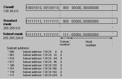
Figure 1-2 Subnet division of an IP address
1.2 Configuring IP Address
The following sections describe IP address configuration tasks:
l Configuring the Hostname and Host IP Address
l Configuring the IP Address of the VLAN Interface
l IP Address Protection Configuration
1.2.1 Configuring the Hostname and Host IP Address
Using this command, you can associate a host name with an IP address. After that, when using an application like telnet, you can use the host name instead of the IP address that is hard to memorize, and the system automatically translates the host name to the IP address.
Perform the following configuration in system view.
Table 1-2 Configure the host name and the corresponding IP address
|
Operation |
Command |
|
Configure the host name and the corresponding IP address |
ip host hostname ip-address |
|
Cancel the host name and the corresponding IP address |
undo ip host hostname [ ip-address ] |
By default, there is no host name associated to any host IP address.
1.2.2 Configuring the IP Address of the VLAN Interface
You can configure an IP address for every VLAN interface of the switch. Generally, it is enough to configure one IP address for an interface. You can also configure 21 IP addresses for an interface at most, so that it can be connected to several subnets. Among these IP addresses, one is the primary IP address and all others are secondary.
Perform the following configuration in VLAN interface view.
Table 1-3 Configure an IP address for a VLAN interface
|
Operation |
Command |
|
Configure an IP address for a VLAN interface |
ip address ip-address { mask | mask-length } [ sub ] |
|
Delete an IP address of a VLAN interface |
undo ip address ip-address { mask | mask-length } [ sub ] |
& Note:
When you use the ip address command to configure IP addresses of VLAN interfaces, the system will prompts if you continue if the IP address you configure is in different network segment from the existing IP address. If you do continue, the IP address of the VLAN interface will be modified. In addition, if the ARP entries (including dynamic ARP entries and static ARP entries) in the original network segment match the new network segment, they will not be removed; otherwise, the ARP entries in the original network segment will be removed.
By default, the IP address of a VLAN interface is null.
1.2.3 IP Address Protection Configuration
I. How IP address protection works
The IP address protection functions can be used for bindings between IP addresses and MAC addresses to ensure that only users using the IP addresses corresponding to the specified MAC addresses can access the Internet while users using other IP addresses cannot. This function works once configured on the switch, without configurations on the server or client.
The IP address protection function needs to work together with the MAC address auto filling function to complete bindings between IP addresses and MAC addresses. When the MAC address auto filling function is enabled, you can configure a static ARP entry that has only an IP address and the MAC address auto filling function can automatically fill the ARP entry with the learned MAC address.
After the IP address protection function is enabled on a VLAN interface, the current interface will no longer dynamically learn ARP mapping entries, and existing dynamic ARP mapping entries will be removed. At the same time, the switch will enable the MAC address auto filling function, so that the user can configure static ARP entries that have only IP addresses. The switch will automatically fill the MAC address in the ARP mapping entries so that only users configured with static ARP entries can have access to the network.
II. IP address protection configuration
The tasks of IP address protection configuration include:
l Configuring auto-fill ARP address
l Enabling IP address protection
Table 1-4 Configure IP address protection
|
Operation |
Command |
Description |
|
Enter system view |
system-view |
- |
|
Configure auto-fill ARP address |
arp static ip-address |
Optional |
|
Enter VLAN interface view |
interface Vlan-interface vlan-id |
- |
|
Enable IP address protection |
ip-protect enable |
By default, the IP address protection function is disabled on VLAN interface |
|
View the IP address protection status of the current VLAN interface |
display this |
You can carry out the display this command in any view |
![]() Caution:
Caution:
l The MAC address auto filling function is enabled only when the IP address protection function is enabled on the interface.
l Once after the initial auto filling of ARP address, the user-configured static ARP entry becomes a normal static ARP entry and cannot be filled again.
1.3 Displaying IP Address
After the above configuration, execute the display command in any view to display the IP addresses configured on interfaces of the network device, and to verify the effect of the configuration.
Table 1-5 Display and debug IP address
|
Operation |
Command |
|
Display all hosts on the network and the corresponding IP addresses |
display ip host |
|
Display the configurations of a VLAN interface |
display ip interface vlan-interface vlan-id |
1.4 IP Address Configuration Example
I. Network requirements
Configure the IP address as 129.2.2.1 and subnet mask as 255.255.255.0 for the VLAN interface 1 of the switch.
II. Network diagram
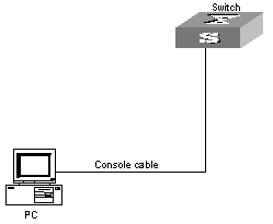
Figure 1-3 Network diagram for IP address configuration
III. Configuration procedure
# Enter VLAN interface 1.
[H3C] interface vlan-interface 1
# Configure the IP address for VLAN interface 1.
[H3C-Vlan-interface1] ip address 129.2.2.1 255.255.255.0
1.5 Troubleshooting IP Address Configuration
Fault 1: The switch cannot ping through a certain host in the LAN.
Troubleshooting can be performed as follows:
1) Check the configuration of the switch. Use the display arp command to view the ARP entry table that the switch maintains.
2) Check which VLAN includes the port of the switch used to connect to the host. Check whether the VLAN has been configured with a VLAN interface. Then check whether the IP address of the VLAN interface and that of the host are on the same network segment.
3) If the configuration is correct, enable the ARP debugging on the switch, and check whether the switch can correctly send and receive ARP packets. If it can only send ARP packets but cannot receive them, errors may occur on the Ethernet physical layer.
Chapter 2 ARP Configuration
2.1 Introduction to ARP
Address Resolution Protocol (ARP) is used to resolve an IP address into a MAC address.
I. Necessity of ARP
An IP address cannot be directly used for communication between network devices because network devices can only identify MAC addresses. An IP address is only an address of a host in the network layer. To send the data packets transmitted through the network layer to the destination host, MAC address of the host is required. So the IP address must be resolved into a MAC address.
II. ARP implementation procedure
When two hosts on the Ethernet need to communicate with each other, they must know the MAC addresses of each other. Every host maintains the IP-MAC address translation table, which is known as the ARP mapping table. A series of maps between IP addresses and MAC addresses of other hosts which recently communicate with the local host are stored in the ARP mapping table. When a dynamic ARP mapping entry is not in use for a specified period of time, the host removes it from the ARP mapping table so as to save the memory space and shorten the interval for the switch to search ARP mapping table.
Suppose there are two hosts on the same network segment: Host A and Host B. The IP address of Host A is IP_A and the IP address of Host B is IP_B. Host A will transmit messages to Host B. Host A checks its own ARP mapping table first to know whether there are corresponding ARP entries of IP_B in the table. If the corresponding MAC address is found, Host A uses the MAC address in the ARP mapping table to encapsulate the IP packet in frame and sends it to Host B. If the corresponding MAC address is not found, Host A puts the IP packet into the send queue, create an ARP request packet and broadcast it throughout the Ethernet. The ARP request packet contains the IP address of Host B and IP address and MAC address of Host A. Since the ARP request packet is broadcasted, all hosts on the network segment can receive the request. However, only the requested host (namely, Host B) needs to process the request. Host B first stores the IP address and the MAC address of the request sender (Host A) in the ARP request packet in its own ARP mapping table. Then, Host B generates an ARP reply packet by adding its own MAC address into the packet, and then send it to Host A. The reply packet is directly sent to Host A in stead of being broadcasted. Receiving the reply packet, Host A extracts the IP address and the corresponding MAC address of Host B and adds them to its own ARP mapping table. Then Host A sends Host B all the packets standing in the queue.
Normally, dynamic ARP takes effect and automatically searches for the resolution from the IP address to the Ethernet MAC address without the help of an administrator.
2.2 Configuring ARP
The ARP mapping table can be maintained dynamically or manually. Usually, the manually configured mapping from the IP addresses to the MAC addresses is known as static ARP. The user can display, add or delete the entries in the ARP mapping table through relevant manual maintenance commands.
The following sections describe static ARP configuration tasks:
l Manually Adding/Deleting Static ARP Mapping Entries
l Configuring the Dynamic ARP Aging Timer
l Adding/Deleting Multicast ARP Ports
l Gratuitous ARP Learning Configuration
2.2.1 Manually Adding/Deleting Static ARP Mapping Entries
Perform the following configuration in system view.
Table 2-1 Manually add/delete static ARP mapping entries
|
Operation |
Command |
|
Manually add a static ARP mapping entry |
arp static ip-address [ mac-address [ vlan-id { interface-type interface-number } ] [ vpn-instance vpn-instance-name ] ] |
|
Manually delete a static ARP mapping entry |
undo arp ip-address |
By default, the ARP mapping table is empty and the address mapping is obtained through dynamic ARP.
Note that:
l As long as a switch operates, its static ARP mapping entries remain valid unless you perform operations that make ARP invalid, such as change or remove VLAN virtual interfaces, remove a VLAN, or remove an interface from a VLAN. These operations cause the corresponding ARP mapping entries to be automatically removed.
l The vlan-id argument must be the ID of a VLAN that has been created by the user, and the Ethernet port specified behind this parameter must belong to the VLAN.
l The argument vpn-instance-name must be the VPN instance name of an existing MPLS VPN.
l ARP map entries with port parameters can be configured on manually aggregated ports or static aggregated ports, but cannot be configured on LACP-enabled dynamic aggregated ports.
l If the mac-address of an ARP entry is a multicast MAC address, the system will assume this ARP entry to be multicast ARP entry.
l Long static ARP can be configured only on manually aggregated ports, but not on static aggregated ported or dynamic aggregated ports.
2.2.2 Configuring the Dynamic ARP Aging Timer
For purpose of flexible configuration, the system provides the following commands to assign dynamic ARP aging period. When the system learns a dynamic ARP entry, its aging period is based on the current value configured.
Perform the following configuration in system view.
Table 2-2 Configure the dynamic ARP aging timer
|
Operation |
Command |
|
Configure the dynamic ARP aging timer |
arp timer aging aging-time |
|
Restore the default dynamic ARP aging time |
undo arp timer aging |
By default, the aging time of dynamic ARP aging timer is 20 minutes.
2.2.3 Adding/Deleting Multicast ARP Ports
The multicast ARP feature allows you to associate a common unicast route to a Layer 2 multicast group, that is, add multiple outgoing ports for an outgoing ARP packet so that the packet can be sent to multiple ports. As a result, a static multicast ARP entry is generated. In brief, a multicast ARP entry is a static ARP entry with a multicast MAC address, which may correspond to multiple ports.
By the multi-port keyword in this command, the switch decides that the port to be added is for a multicast ARP entry. Only one port can be added every time the command is executed. If the ARP entry does not exist, a new entry is generated. If the port has already been in the entry, no further processing is made.
Perform the following configuration in system view.
Table 2-3 Add multicast ARP ports
|
Configuration step |
Command |
Description |
|
Enter system view |
system-view |
- |
|
Add multicast ARP ports |
arp static ip-address mac-address vlan-id multi-port interface-type interface-number [ vpn-instance vpn-instance-name ] |
- |
To cancel the configuration, use the corresponding undo command.
After the configuration, you can use the display arp multi-port command in any view to check the detailed information about multicast ARP configuration.
![]() Caution:
Caution:
l You cannot configure multicast ARP for aggregation ports. Otherwise, the system will prompt error message.
l You cannot add a port in a multicast ARP entry to an aggregation group; if you want to do this, you must first delete the port from any multicast ARP entry it belongs to.
l At present, the outgoing ports in the same multicast ARP entry cannot be in different boards.
l Multicast static ARP can cover dynamic ARP, short static ARP and long static ARP, but not the other way around.
2.2.4 ARP Proxy Configuration
With the Super VLAN function enabled, the ARP proxy function is also needed to enable Layer 3 communications between sub-VLANs. If you enable the ARP proxy function for a network device that is connected to two networks simultaneously, the network device enables two ports in these two networks to communicate with each other on Layer 3 by forwarding ARP requests between the two networks even if the two ports are isolated from each other on Layer 2.
& Note:
You must enable isolate-user-vlan feature for all the devices connected to the VLAN with ARP proxy enabled.
|
Operation |
Command |
Description |
|
Enter system view |
system-view |
- |
|
Enter VLAN view |
vlan vlan-id |
vlan-id is the ID of a VLAN |
|
Enable ARP proxy |
arp proxy enable |
By default, ARP proxy function is disabled. |
Use the undo form of the command to cancel the configuration.
2.2.5 Gratuitous ARP Learning Configuration
I. Introduction to Gratuitous ARP Packets
The following are the characteristics of gratuitous ARP packets:
l Both source and destination IP addresses carried in a gratuitous ARP packet are the local addresses, and the source MAC address carried in it is the local MAC addresses.
l If a device finds that the IP addresses carried in a received gratuitous packet conflict with those of its own, it returns an ARP response to the sending device to notify of the IP address conflict.
By sending gratuitous ARP packets, a network device can:
l Determine whether or not IP address conflicts exist between it and other network devices.
l Trigger other network devices to update its hardware address stored in their caches.
With the gratuitous ARP packet learning function enabled, a network device stores the ARP address carried in a received gratuitous ARP packet in its ARP address table if no ARP address in the cache of the network device matches the IP address carried by the gratuitous ARP packet. If the cache contains an ARP entry that matches the received gratuitous ARP packet, the switch updates the ARP entry using the hardware address of the sender carried in the gratuitous ARP packet. A switch operates like this whenever it receives an ARP packet.
II. Gratuitous ARP packet learning configuration
The following table lists the operations to configure the gratuitous ARP packet learning function.
Table 2-5 Configure the gratuitous ARP packet learning function
|
Operation |
Command |
Description |
|
Enter system view |
system-view |
- |
|
Enable the gratuitous ARP packet learning function |
gratuitous-arp-learning enable |
Required By default, the gratuitous ARP packet learning function is enabled. |
2.3 Displaying and Debugging ARP
After the above configuration, execute the display command in any view to display the running of the ARP configuration, and to verify the effect of the configuration.
Execute the reset command in user view to clear ARP mapping table. Execute the debugging command in user view to debug ARP configuration.
Table 2-6 Display and debug ARP
|
Operation |
Command |
|
Display ARP mapping table |
display arp [ ip-address | [ dynamic | static ] [ | { begin | include | exclude } text ] ] |
|
Display the current setting of the dynamic ARP aging timer |
display arp timer aging |
|
Display multicast ARP configuration information |
display arp multi-port [ ip-address ] |
|
Display ARP proxy information |
display arp proxy [ vlan vlan-id] |
|
Reset ARP mapping table |
reset arp [ dynamic | static | interface { interface-type interface-number } | all ] |
|
Enable ARP information debugging |
debugging arp { error | info | packet } |
|
Disable ARP information debugging |
undo debugging arp { error | info | packet } |
Chapter 3 ARP Table Size Configuration
3.1 Introduction to ARP Table Size Configuration
You can manually configure the maximum numbers of ARP entries (that is, the sizes of ARP tables) on an S9500 routing switch to meet your actual needs.
Table 3-1 Specifications and numbers of ARP entries on cards with different model suffixes
|
Model suffix |
IP address format and number of FIB entries supported |
MPLS support |
Maximum number of ARP entries supported by the whole switch if the card exists in the system |
Maximum number of ARP entries supported by the card |
Maximum number of aggregation ARP entries supported by the card |
|
B |
IPv4-128K |
Not supported |
4K |
4K |
0K, 1K, 3K |
|
DA |
IPv4-128K/IPv6-7K |
||||
|
DB |
IPv4-128K/IPv6-64K |
||||
|
DC |
IPv4-256K/IPv6-128K |
||||
|
C |
IPv4-128K |
Supported |
4K, 64K |
4K, 5K, 6K, 7K, 8K |
0K, 1K, 3K, 7K, 8K |
|
CA |
IPv4-256K |
||||
|
CB |
IPv4-512K |
& Note:
You can distinguish the model suffix of a card by the silkscreen on the right above of the front panel. For example, the silkscreen of the LSB1GP12B0 card is GP12B, and so the suffix of this card is B.
![]() Caution:
Caution:
l After the configuration of a short static ARP entry, the system will include it into the number of normal ARP entries. If the short static ARP entry resolved from a non-aggregated port, the count will remain unchanged; if the short static ARP entry is resolved from an aggregated port, it will be deducted from the number of normal ARP entries and included into the number of aggregation ARP entries.
l As a short static ARP entry is included into the number of normal ARP entries like a normal long static ARP entry, if a card is configured to support up to 8K aggregation ARP entries, the card does not support the configuration of neither kinds.
3.2 Dynamic Configuration of the Number of ARP Entries
3.2.1 Configuration Task Overview
Dynamic configuration of the number of ARP entries includes:
l Configuring the maximum number of ARP entries supported by a card
l Configuring the maximum number of aggregation ARP entries supported by a card
l Configuring the number of ARP entries supported by the system
3.2.2 Configuring the Number of ARP Entries Dynamically
Table 3-2 Configure the number of ARP entries dynamically
|
Operation |
Command |
Description |
|
Enter system view |
system-view |
- |
|
Configure the maximum number of ARP entries supported by a card |
arp max-entry slot-num max-num |
By default, a card supports up to 4K ARP entries. |
|
Configure the maximum number of aggregation ARP entries supported by a card |
arp max-aggregation-entry max-aggnum |
By default, a card supports up to 1K aggregation ARP entries. |
|
Configure the number of ARP entries supported by the system |
arp enable size { 4 | 64 } |
By default, the system supports 4K ARP entries. |
To remove a configuration, use the corresponding undo command.
![]() Caution:
Caution:
l You must restart the system to validate the above-mentioned dynamic configurations of the numbers of ARP entries.
l After the dynamic configuration of the number of ARP entries, do not replace any card or slot before the system is restarted. Otherwise, the configuration will be invalid.
l After the dynamic configuration of the number of ARP entries, do not perform primary/secondary switchover before the system is restarted. Otherwise, the configuration will be invalid.
3.3 Displaying ARP Table Size Configuration
After performing the above configurations, you can execute the display command in any view to display the maximum numbers of ARP entries to verify the configurations.
Table 3-3 Display ARP table size configuration
|
Operation |
Command |
Description |
|
Display the current maximum numbers of ARP entries and the intending counterparts that will take effect after the switch is restarted next time |
display arp max-entry |
You can carry out the display command in any view. |
3.4 Configuration Example
I. Network requirements
A host is connected to a S9500 series routing switch. The model names of all the cards in the switch system are suffixed with C, CA, or CB.
II. Network diagram

Figure 3-1 Diagram for ARP table size configuration
III. Configuration procedure
# Configure the maximum number of ARP entries supported by the whole switch to 64K.
<H3C> system-view
System View: return to User View with Ctrl+Z.
[H3C] arp enable size 64
The configuration won't be enable until the system is rebooted
# Configure the maximum number of ARP entries supported by the interface card in slot 2 to 8K.
[H3C] arp max-entry 2 8
The configuration won't be enable until the system is rebooted
# Configure the maximum number of aggregation ARP entries supported by each interface card in the system to 8K.
[H3C] arp max-aggregation-entry 8
The configuration won't be enable until the system is rebooted
Restart the system for the configurations to take effect.
Chapter 4 DHCP Configuration
4.1 Some Concepts about DHCP
4.1.1 BOOTP Relay Agent
Bootstrap protocol (BOOTP) relay agent is an Internet host or router that transports DHCP messages between the DHCP server and DHCP clients. BOOTP is designed for remote boot, mainly to notify the connected client about the location of the boot file.
DHCP is an extension of the BOOTP mechanism. This feature enables an existing BOOTP client to interoperate with the DHCP server without changing the installed software. RFC 1542 describes in detail the interactions among BOOTP, DHCP client and DHCP server.
4.1.2 DHCP and BOOTP Relay Agent
Like BOOTP, DHCP also works in the Client/Server mode. This protocol enables a DHCP client to request dynamically the DHCP server for the configuration information, including important parameters such as the allocated IP address, subnet mast, and default gateway, and the DHCP server can configure these parameters for the client conveniently.
DHCP provide a framework about how to set a host on a TCP/IP network. DHCP is derived from BOOTP, and possesses more function such as automatic allocation of reusable network addresses and additional configuration options. DHCP can act as a BOOTP relay agent, so a DHCP user and a BOOTP user can interact with each other.
The message format of DHCP is based on the message format of BOOTP, so that it can work as a relay agent and allow the coordination (interoperability) between existing BOOTP clients and the DHCP server. The use of a BOOTP relay agent makes it unnecessary to employ a DHCP server for every physical network segment.
DHCP defers from BOOTP in that:
l DHCP defines a mechanism through which a client can be allocated with a network address valid for a fixed lease period. In addition, it allows for continuous reallocation of network addresses to different clients.
l DHCP provides a mechanism through which a client is allowed to obtain all IP configuration parameter for subsequent operations.
4.1.3 How DHCP Works
This is a world where networks are ever-growing in both size and complexity, and the network configuration is getting more and more complex. As is often the case, the number of hosts in a network exceeds that of the available IP addresses, and position changes of hosts (when users carry their laptops from here to there, or move to a wireless network) require reassigned new IP addresses. Dynamic host configuration protocol (DHCP) is designed to accommodate this context. DHCP adopts client/server model, where DHCP clients send requests to the DHCP server dynamically and the DHCP server in turn returns corresponding configuration information (such as IP addresses) according to the policies configured for it.
A typical DHCP implementation comprises a DHCP server and multiple DHCP clients (PCs or laptops). Figure 4-1 illustrates a network that employs DHCP.
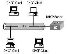
Figure 4-1 Network diagram for DHCP
I. IP address assignment
1) IP address assignment policy
Different types of clients have different requirements for IP addresses. Servers usually require long-term fixed IP addresses, some hosts may require automatically assigned long-term fixed IP addresses , and some hosts may only require dynamically assigned temporary IP addresses.
A DHCP server provides three policies to meet these requirements.
l Manual IP address assignment. The administrator assigns fixed IP addresses to DHCP clients that are of special uses, such as a WWW server.
l Automatic IP address assignment. The DHCP server automatically assigns fixed IP addresses to DHCP clients when they connect to the network for the first time. After that, the IP addresses are always occupied by the DHCP clients.
l Dynamic IP address assignment. The DHCP server leases IP addresses to DHCP clients for predetermined period of time and reclaims them at the expiration of the period. In this case, a DHCP client must reapply for an IP address regularly. This is the common case for normal users.
2) IP address assignment order.
The DHCP server assigns IP addresses except the forbidden ones to clients in the following orders.
l IP addresses in the address pool of the DHCP server that are statically bound to the MAC addresses of the DHCP clients.
l IP addresses that are reclaimed by the DHCP server. That is, those in the Requested IP Addr Option fields of DHCP Discover packets sent by DHCP clients.
l The first available IP address in the address pool the DHCP server finds.
l The first expired or once conflicted IP address it finds. A DHCP server returns an error if it cannot find any available IP address from all these types of IP addresses when assigning an IP address.
3) Types of address pools of DHCP server
l Global address pool, valid for the entire switch. An address pool of this type is created using the dhcp server ip-pool command in system view.
l VLAN interface address pool, valid for a specific VLAN interface. An address pool of this type is created by the system when the VLAN interface is configured with a legal unicast IP address and you specify to assign IP addresses in VLAN interface address pool using the dhcp select interface command in VLAN interface view. The address range of the available addresses is that of the network segment the VLAN interface resides.
II. Communications between DHCP clients and DHCP server
To obtain valid dynamic IP addresses, the DHCP clients exchange different information with the DHCP server in different phases. Usually, three modes are involved:
1) First round registration
A DHCP client goes through the following four steps when it accesses a network for the first time:
l Discovery. The DHCP client tries to find a DHCP server by broadcasting a DHCP_Discover packet in the network. (Only DHCP servers respond to this type of packet.)
l Provision. Each DHCP server that receives the DHCP_Discover packet selects an available IP address from an address pool and sends a DHCP_Offer packet that carries the selected IP address and other configuration information to the DHCP client.
l Selection. The DHCP client only receives the first arriving DHCP_Offer packet if there are DHCP_Offer packets from several DHCP servers. Then, it retrieves the IP address carried in the packet, and broadcasts a DHCP_Request packet to each DHCP server. The packet contains the IP address carried by the DHCP_Offer packet.
l Acknowledgement. Upon receiving the DHCP_Request packet, the DHCP server that owns the IP address the DHCP_Request packet carries sends a DHCP_ACK packet to the DHCP client. And then the DHCP client binds TCP/IP protocol components to its network adapter.
l IP addresses offered by other DHCP servers (if any) through DHCP_Offer packets but not selected by the DHCP client are still available for other clients.
2) Second round registration
A second round registration goes through the following steps:
l After going through the first round registration successfully and logging out, when the DHCP client logs on to the network again, it directly broadcasts a DHCP_Request packet that contains the IP address assigned to it in the first round registration instead of a DHCP_Discover packet. .
l Upon receiving the DHCP_Request packet, if the IP address carried in the packet is still available, the DHCP server owning the IP address answers with a DHCP_ACK packet to enable the DHCP client to use the IP address again.
l If the IP address is not available (for example, it is occupied by other DHCP client), the DHCP server answers with a DHCP_NAK packet, which enables the DHCP client to go through steps in the first round registration.
3) Prolonging the lease time of IP address
An IP address assigned dynamically is valid for a specified lease time and will be reclaimed by the DHCP server when the time expires. So the DHCP client must update the lease to prolong the lease time if it is to use the IP address for a longer time.
By default, a DHCP client updates its IP address lease automatically by sending a DHCP_Request packet to the DHCP server when half of the lease time elapses. The DHCP server, in turn, answers with a DHCP_ACK packet to notify the DHCP client of the new lease.
4.2 Configuring General DHCP
General DHCP configuration refers to those that are applicable to both DHCP server and DHCP relay.
The following sections describe the general DHCP configuration tasks:
l Enabling/Disabling DHCP Service
l Configuring Processing Method of DHCP Packets
l Enabling/Disabling Fake DHCP Server Detection
4.2.1 Enabling/Disabling DHCP Service
For both DHCP server and DHCP relay, you must enable the DHCP service first before performing other DHCP configurations. The other related DHCP configurations take effect only after the DHCP service is enabled.
Perform the following configuration in system view.
Table 4-1 Enable/Disable DHCP service
|
Operation |
Command |
|
Enable DHCP service |
dhcp enable |
|
Disable DHCP service |
undo dhcp enable |
DHCP service is disabled by default.
4.2.2 Configuring Processing Method of DHCP Packets
You can perform the configurations listed in the following tables on your switch. After that, the switch processes the DHCP packets it received from DHCP clients in the methods you have configured.
Perform the following configuration in VLAN interface view to configure the processing method of DHCP packets for current VLAN interface.
Table 4-2 Configure the processing method for current VLN interface
|
Operation |
Command |
|
Specify to forward DHCP packets to local DHCP server and let the local server assign IP addresses in global address pools to DHCP clients |
dhcp select global |
|
Specify to forward DHCP packets to local DHCP server and let the local server assign IP addresses in VLAN interface address pool to DHCP clients |
dhcp select interface |
|
Specify to forward DHCP packets to remote DHCP servers. In this case, the current switch operates as a DHCP relay, and IP addresses are assigned by DHCP servers located in other networks |
dhcp select relay |
|
Revert to the default processing mode |
undo dhcp select |
![]() Caution:
Caution:
The dhcp select interface command cannot be used together with the ip relay address or dhcp relay security address-check enable command.
Perform the following configuration in system view to configure the processing method of DHCP packets for multiple VLAN interfaces.
Table 4-3 Configure the processing method for multiple VLAN interfaces
|
Operation |
Command |
|
Specify to forward DHCP packets to local DHCP server and let the local server assign IP addresses in global address pools to DHCP clients |
dhcp select global { interface vlan-interface vlan-id [ to vlan-interface vlan-id ] | all } |
|
Specify to forward DHCP packets to local DHCP server and let the local server assign IP addresses in VLAN interface address pool to DHCP clients |
dhcp select interface { interface vlan-interface vlan-id [ to vlan-interface vlan-id ] | all } |
|
Specify to forward DHCP packets to remote DHCP servers. In this case, the current switch operates as a DHCP relay, and IP addresses are assigned by DHCP servers located in other networks |
dhcp select relay { interface vlan-interface vlan-id [ to vlan-interface vlan-id ] | all } |
|
Revert to the default processing mode |
undo dhcp select { interface vlan-interface vlan-id [ to vlan-interface vlan-id ] | all } |
By default, DHCP packets are processed in global method. That is, DHCP packets are forwarded to local DHCP server and IP addresses in global address pools are assigned.
4.2.3 Enabling/Disabling Fake DHCP Server Detection
If an unauthorized DHCP server exists in a network, it also answers when users in the network request IP addresses, and then interacts with the DHCP clients. This causes that the users cannot obtain correct IP addresses to access network. This kind of DHCP servers are known as fake DHCP servers.
With fake DHCP server detection enabled, the switch can record information (such as the IP addresses) about the DHCP servers. This helps administrators to detect fake DHCP servers in time and take proper measures.
Perform the following configuration in system view.
Table 4-4 Enable/Disable fake DHCP server detection
|
Operation |
Command |
|
Enable fake DHCP server detection |
dhcp server detect |
|
Disable fake DHCP server detection |
undo dhcp server detect |
Fake DHCP server detection is disabled by default.
4.3 Configuring DHCP Server
The following sections describe the DHCP server configuration tasks:
l Creating a Global DHCP IP Address Pool
l Configuring IP Address Assignment Mode
l Forbidding Specified IP Addresses to Be Automatically Assigned
l Configuring Lease Time For DHCP Address Pool
l Configuring DHCP Client Domain Names
l Configuring DNS Server Address for DHCP Clients
l Configuring NetBIOS Server Address for DHCP Clients
l Configuring NetBIOS Node Type for DHCP Clients
l Configuring Custom DHCP Options
l Configuring Outbound Gateway Address for DHCP Clients
l Configuring Parameters for DHCP Server to Send Ping Packets
& Note:
Some of the above DHCP configurations can be performed for global IP address pools, IP address pool of current VLAN interface, or IP address pools of multiple specified VLAN interface respectively. They are:
l Configuring lease time for DHCP address pool
l Configuring DHCP client domain names
l Configuring DNS server address for DHCP clients
l Configuring NetBIOS server address for DHCP clients
l Configuring NetBIOS node type for DHCP clients
l Configuring DHCP custom options
4.3.1 Creating a Global DHCP IP Address Pool
An IP address pool contains IP addresses that can be assigned to DHCP clients. In response to DHCP request sent by a DHCP client, the DHCP server selects an appropriate IP address pool based on your configuration, choose an available IP address from the pool, and sends the IP address and other parameters (such as the lease time of the IP address) to the DHCP client. At present, you can configure up to 128 global DHCP address pools for a DHCP server.
The address pools of a DHCP server are hierarchically grouped like a tree. The root holds the IP address of the network segment, the branches hold the subnet IP addresses, and finally, the leaves hold the IP addresses of DHCP clients, which are manually bound to the corresponding network adapters. Such a structure enables configurations to be inherited. That is, configurations of the network segment can be inherited by its subnets, whose configurations in turn can be inherited by their clients. So, you can configure the parameters (such as domain name) that are common to all levels in the address pool structure or some subnets only for the network segment or for corresponding subnets.
The display dhcp server tree command displays the tree-like structure of address pool, where address pools on the same level are sorted by the time they are created.
The dhcp server ip-pool command can be used to create a global DHCP address pool and enter the corresponding address pool view. If the address pool already exists, this command brings you to the address pool view directly.
Perform the following configuration in system view.
Table 4-5 Create a global DHCP address pool
|
Operation |
Command |
|
Create a DHCP address pool and enter the corresponding DHCP address pool view |
dhcp server ip-pool pool-name |
|
Remove a DHCP address pool |
undo dhcp server ip-pool pool-name |
By default, no global DHCP address pool is created.
Note that a VLAN interface address pool is created by the system after a legal unicast IP address is assigned to the VLAN interface and you specify to assign IP addresses in VLAN interface address pool by using the dhcp select interface command in VLAN interface view.
4.3.2 Configuring IP Address Assignment Mode
IP address can be assigned in two modes: static binding and dynamic assignment. You can statically bind an IP address in an address pool to the MAC address of a client or configure a address range to allow the DHCP server dynamic allocate the addresses in the range to DHCP clients. The two modes cannot coexist in a global DHCP address pool, but they can coexist in a VLAN interface address pool (but those that are dynamically assigned have the same network segment as that of the IP address of the VLAN interface).
For the dynamic assignment mode, you must specify the range of the addresses to be dynamically assigned. A global DHCP address pool whose IP addresses are statically bound to DHCP clients is actually a special kind of DHCP address pool.
I. Configuring static address binding for a global DHCP address pool
fixed IP address to the MAC address of a DHCP client who needs fixed IP address. After that, when the client requests for an IP address, the DHCP server finds (according to the MAC address) and assigns the fixed IP address to the client. At present, only one-to-one MAC-IP binding is supported for global DHCP address pool.
Perform the following configuration in DHCP address pool view.
Table 4-6 Configure static address binding for a global DHCP address pool
|
Operation |
Command |
|
Configure an IP address to be statically bound |
static-bind ip-address ip-address [ mask netmask ] |
|
Free a statically bound IP address |
undo static-bind ip-address |
|
Configure a MAC address to be statically bound |
static-bind mac-address mac-address |
|
Free a statically bound MAC address |
undo static-bind mac-address |
IP addresses in a global DHCP address pool are not statically bound by default.
& Note:
The static-bind ip-address command and the static-bind mac-address command must be used together as a pair when you configure static binding entries. When you re-execute the command pair with the same IP address/MAC address, the newly configured IP address/MAC address overwrites the existing one.
II. Configuring static address binding for a VLAN interface address pool
At present, a VLAN interface DHCP address pool supports one-to-multiple MAC-IP address binding.
Perform the following configuration in VALN interface view.
Table 4-7 Configure static address binding for a VLAN interface address pool
|
Operation |
Command |
|
Configure static address binding for the current VLAN interface address pool |
dhcp server static-bind ip-address ip-address mac-address mac-address |
|
Remove a statically bound IP address entry |
undo dhcp server static-bind { ip-address ip-address | mac-address mac-address } |
IP addresses in the address pool of a VLAN interface are not statically bound by default.
![]() Caution:
Caution:
A binding in a VLAN interface address pool cannot be overwritten directly. If an IP-to-MAC address binding entry is configured and you want to modify it, you must remove it and redefine a new one.
III. Configuring dynamic IP address assignment
If you specify to assign IP addresses dynamically, that is, IP addresses are leased permanently or temporarily, you need to configure an available address range.
Perform the following configuration in DHCP address pool view.
Table 4-8 Configure an address range for dynamic IP address assignment
|
Operation |
Command |
|
Configure an address range for dynamic IP address assignment |
network ip-address [ mask netmask ] |
|
Remove an dynamic assignment address range |
undo network |
By default, no IP address range is configured for dynamic IP address assignment.
Each DHCP address pool can be configured with only one address range. If you execute the network command multiple times, then only the last configured address range works.
4.3.3 Forbidding Specified IP Addresses to Be Automatically Assigned
You can use the command here to prevent a DHCP server from assigning IP addresses that are already occupied by such network devices as gateways and file transfer protocol (FTP) servers to other DHCP clients to avoid IP address conflicts.
Perform the following configuration in system view.
Table 4-9 Forbid specified IP addresses to be automatically assigned
|
Operation |
Command |
|
Forbid specified IP addresses to be automatically assigned |
dhcp server forbidden-ip low-ip-address [ high-ip-address ] |
|
Cancel the forbiddance |
undo dhcp server forbidden-ip low-ip-address [ high-ip-address ] |
All IP addresses in a DHCP address pool can be automatically assigned by default.
You can set multiple IP address ranges that are not assigned automatically by executing the dhcp server forbidden-ip command multiple times.
4.3.4 Configuring Lease Time For DHCP Address Pool
I. Configuring a lease time for a global DHCP address pool
Perform the following configuration in DHCP address pool view.
Table 4-10 Configure a lease time for a global DHCP address pool
|
Operation |
Command |
|
Configure a lease time for a global DHCP address pool |
expired { day day [ hour hour [ minute minute ] ] | unlimited } |
|
Restore the lease time of a global DHCP address pool to the default value |
undo expired |
II. Configuring a lease time for current VLAN interface
Perform the following configuration in VLAN interface view.
Table 4-11 Configure a lease time for current VLAN interface
|
Operation |
Command |
|
Configure a lease time for DHCP address pool of current VLAN interface |
dhcp server expired { day day [ hour hour [ minute minute ] ] | unlimited } |
|
Restore the lease time of DHCP address pool of current VLAN interface to the default value |
undo dhcp server expired |
III. Configuring a lease time for multiple VLAN interfaces
Perform the following configuration in system view.
Table 4-12 Configure a lease time for multiple VLAN interfaces
|
Operation |
Command |
|
Configure a lease time for DHCP address pools of multiple VLAN interfaces |
dhcp server expired { day day [ hour hour [ minute minute ] ] | unlimited } { interface vlan-interface vlan-id [ to vlan-interface vlan-id ] | all } |
|
Restore the lease time of DHCP address pools of multiple VLAN interfaces to the default value |
undo dhcp server expired { interface vlan-interface vlan-id [ to vlan-interface vlan-id ] | all } |
The default lease times for global address pools and VLAN interface address pools are all one day.
4.3.5 Configuring DHCP Client Domain Names
You can configure a domain name used by DHCP clients for each address pool on a DHCP server.
I. Configuring a DHCP client domain name for a global DHCP address pool
Perform the following configuration in DHCP address pool view.
Table 4-13 Configure a DHCP client domain name for a global DHCP address pool
|
Operation |
Command |
|
Configure a DHCP client domain name for a global DHCP address pool |
domain-name domain-name |
|
Remove the DHCP client domain name configured for a global DHCP address pool |
undo domain-name |
II. Configuring a DHCP client domain name for current VLAN interface
Perform the following configuration in VLAN interface view.
Table 4-14 Configure a DHCP client domain name for current VLAN interface
|
Operation |
Command |
|
Configure a DHCP client domain name for the DHCP address pool of the current VLAN interface |
dhcp server domain-name domain-name |
|
Remove the DHCP client domain name configured for the DHCP address pool of the current VLAN interface |
undo dhcp server domain-name |
III. Configuring a DHCP client domain name for multiple VLAN interfaces
Perform the following configuration in system view.
Table 4-15 Configure a DHCP client domain name for multiple VLAN interfaces
|
Operation |
Command |
|
Configure a DHCP client domain name for DHCP address pools of multiple VLAN interfaces |
dhcp server domain-name domain-name { interface vlan-interface vlan-id [ to vlan-interface vlan-id ] | all } |
|
Remove the DHCP client domain name configured for DHCP address pools of multiple VLAN interfaces |
undo dhcp server domain-name domain-name { interface vlan-interface vlan-id [ to vlan-interface vlan-id ] | all } |
By default, global address pools and VLAN interface address pools are not configured with any DHCP client domain name.
If you execute the dhcp server domain-name command multiple times, the newly configured DHCP client domain name overwrites the existing one.
4.3.6 Configuring DNS Server Address for DHCP Clients
When a host uses a domain name to access the Internet, the domain name must be translated into an IP address. Domain name system (DNS) is responsible for the translation. Therefore, when a DHCP server assigns an IP address to a DHCP client, it must also send a DNS server address to the client. At present, you can configure up to eight DNS server addresses for one DHCP address pool.
I. Configuring DNS server address for a global DHCP address pool
Perform the following configuration in DHCP address pool view.
Table 4-16 Configure DNS server address for a global DHCP address pool
|
Operation |
Command |
|
Configure one or more DNS server addresses for a global DHCP address pool |
dns-list ip-address [ ip-address ] |
|
Remove one or all DNS server addresses configured for a global DHCP address pool |
undo dns-list { ip-address | all } |
II. Configuring DNS server address for current VLAN interface
Perform the following configuration in VLAN interface view.
Table 4-17 Configure DNS server address for current VLAN interface
|
Operation |
Command |
|
Configure one or more DNS server addresses for the DHCP address pool of the current VLAN interface |
dhcp server dns-list ip-address [ ip-address ] |
|
Remove one or all DNS server addresses configured for the DHCP address pool of the current VLAN interface |
undo dhcp server dns-list { ip-address | all } |
III. Configuring DNS server address for multiple VLAN interfaces
Perform the following configuration in system view.
Table 4-18 Configure DNS server address for multiple VLAN interfaces
|
Operation |
Command |
|
Configure one or more DNS server addresses for the DHCP address pools of multiple VLAN interfaces |
dhcp server dns-list ip-address [ ip-address ] { interface vlan-interface vlan-id [ to vlan-interface vlan-id ] | all } |
|
Remove one or all DNS server addresses configured for the DHCP address pools of multiple VLAN interfaces |
undo dhcp server dns-list { ip-address | all } { interface vlan-interface vlan-id [ to vlan-interface vlan-id ] | all } |
By default, no DNS server address is configured for global and VLAN interface address pools.
If you execute the dhcp server dns-list command multiple times, the newly configured IP addresses overwrite the existing ones.
4.3.7 Configuring NetBIOS Server Address for DHCP Clients
For clients running a Windows operating system and communicating through the NetBIOS protocol, translations between host name and IP address are carried out by Windows Internet Naming Service (WINS) servers. So you need to perform configurations concerning WINS for these clients. At present, you can configure up to eight NetBIOS server addresses for a DHCP address pool.
I. Configuring NetBIOS server address for a global DHCP address pool
Perform the following configuration in DHCP address pool view.
Table 4-19 Configure NetBIOS server address for a global DHCP address pool
|
Operation |
Command |
|
Configure one or more NetBIOS server addresses for a global DHCP address pool |
nbns-list ip-address [ ip-address ] |
|
Remove one or all NetBIOS server addresses configured for a global DHCP address pool |
undo nbns-list { ip-address | all } |
II. Configuring NetBIOS server address for current VLAN interface
Perform the following configuration in VLAN interface view.
Table 4-20 Configure NetBIOS server address for current VLAN interface
|
Operation |
Command |
|
Configure one or more NetBIOS server addresses for the DHCP address pool of current VLAN interface |
dhcp server nbns-list ip-address [ ip-address ] |
|
Remove one or all NetBIOS server addresses configured for the DHCP address pool of the current VLAN interface |
undo dhcp server nbns-list { ip-address | all } |
III. Configuring NetBIOS server address for multiple VLAN interfaces
Perform the following configuration in system view.
Table 4-21 Configure NetBIOS server address for multiple VLAN interfaces
|
Operation |
Command |
|
Configure one or more NetBIOS server addresses for the DHCP address pools of multiple VLAN interfaces |
dhcp server nbns-list ip-address [ ip-address ] { interface vlan-interface vlan-id [ to vlan-interface vlan-id ] | all } |
|
Remove one or all NetBIOS server addresses configured for the DHCP address pools of multiple VLAN interfaces |
undo dhcp server nbns-list { ip-address | all } { interface vlan-interface vlan-id [ to vlan-interface vlan-id ] | all } |
By default, no NetBIOS server address is configured for global and VLAN interface address pools.
If you execute the dhcp server nbns-list command multiple times, the newly configured IP addresses overwrite the existing ones.
4.3.8 Configuring NetBIOS Node Type for DHCP Clients
l b-node: Nodes of this type establish their mappings by broadcasting. (b stands for broadcast.)
l p-node: Nodes of this type establish their mappings by communicating with NetBIOS server. (p stands for peer-to-peer.)
l m-node: Nodes of this type are p nodes which take some broadcast features. (m stands for mixed.)
l h-node: Nodes of this type are b nodes which take peer-to-peer mechanism. (h stands for hybrid.)
I. Configuring NetBIOS node type for a global DHCP address pool
Perform the following configuration in DHCP address pool view.
Table 4-22 Configure a NetBIOS node type for a global DHCP address pool
|
Operation |
Command |
|
Configure the NetBIOS node type for a global DHCP address pool |
netbios-type { b-node | h-node | m-node | p-node } |
|
Cancel the NetBIOS node type configuration for a global DHCP address pool |
undo netbios-type |
II. Configuring NetBIOS node type for current VLAN interface
Perform the following configuration in VLAN interface view.
Table 4-23 Configure a NetBIOS node type for current VLAN interface
|
Operation |
Command |
|
Configure the NetBIOS node type for DHCP clients of the current VLAN interface DHCP address pool |
dhcp server netbios-type { b-node | h-node | m-node | p-node } |
|
Remove NetBIOS node type configured for DHCP clients of the current VLAN interface DHCP address pool |
undo dhcp server netbios-type |
III. Configuring NetBIOS node type for multiple VLAN interfaces
Perform the following configuration in system view.
Table 4-24 Configure a NetBIOS node type for multiple VLAN interfaces
|
Operation |
Command |
|
Configure NetBIOS node types for DHCP clients of multiple VLAN interface DHCP address pools |
dhcp server netbios-type { b-node | h-node | m-node | p-node } { interface vlan-interface vlan-id [ to vlan-interface vlan-id ] | all } |
|
Remove NetBIOS node type configurations of multiple VLAN interface DHCP address pools |
undo dhcp server netbios-type { interface vlan-interface vlan-id [ to vlan-interface vlan-id ] | all } |
By default, the DHCP clients of global and VLAN interface address pools are all of h-node type.
4.3.9 Configuring Custom DHCP Options
With the evolvement of DHCP, new options come forth continuously. To utilize these options, you can manually add them to the property list of a DHCP server.
I. Configuring custom DHCP options for a global DHCP address pool
Perform the following configuration in DHCP address pool view.
Table 4-25 Configure a custom DHCP options for a global DHCP address pool
|
Operation |
Command |
|
Configure a custom DHCP option for a global DHCP address pool |
option code { ascii ascii-string | hex hex-string | ip-address ip-address [ ip-address ] } |
|
Remove a custom DHCP option configured for a global DHCP address pool |
undo option code |
II. Configuring custom DHCP options for current VLAN interface
Perform the following configuration in VLAN interface view.
Table 4-26 Configure custom DHCP options for current VLAN interface
|
Operation |
Command |
|
Configure a custom DHCP option for DHCP address pool of the current VLAN interface |
dhcp server option code { ascii ascii-string | hex hex-string | ip-address ip-address [ ip-address ] } |
|
Remove a custom DHCP option configured for the DHCP address pool of the current VLAN interface |
undo dhcp server option code |
III. Configuring custom DHCP options for multiple VLAN interfaces
Perform the following configuration in system view.
Table 4-27 Configure custom DHCP options for multiple VLAN interfaces
|
Operation |
Command |
|
Configure a custom DHCP option for DHCP address pools of multiple VLAN interfaces |
dhcp server option code { ascii ascii-string | hex hex-string | ip-address ip-address [ ip-address ] } { interface vlan-interface vlan-id [ to vlan-interface vlan-id ] | all } |
|
Remove a custom DHCP option configured for DHCP address pools of multiple VLAN interfaces |
undo dhcp server option code { interface vlan-interface vlan-id [ to vlan-interface vlan-id ] | all } |
If you execute the dhcp server option command multiple times, the newly configured option overwrites the existing one.
4.3.10 Configuring Outbound Gateway Address for DHCP Clients
An outbound gateway enables DHCP clients to access external network devices. Packets destined for external networks are forwarded by outbound gateways. At present, you can configure up to eight IP addresses for outbound gateways.
Perform the following configuration in DHCP address pool view.
Table 4-28 Configure outbound gateway address for DHCP clients
|
Operation |
Command |
|
Configure one or more outbound gateway addresses for DHCP clients |
gateway-list ip-address [ ip-address ] |
|
Remove one or all outbound gateway addresses configured for DHCP clients |
undo gateway-list { ip-address | all } |
By default, no outbound gateway address is configured for DHCP clients.
If you execute the gateway-list command multiple times, the newly configured IP addresses overwrite the existing ones.
4.3.11 Configuring Parameters for DHCP Server to Send Ping Packets
Perform the following configuration in system view.
Table 4-29 Configure parameters for DHCP server to send ping packets
|
Operation |
Command |
|
Set the maximum number of ping packets the DHCP is allowed to send |
dhcp server ping packets number |
|
Revert to the default maximum number |
undo dhcp server ping packets |
|
Set the maximum duration for the DHCP server to wait for response to a ping packet |
dhcp server ping timeout milliseconds |
|
Revert to the default maximum duration |
undo dhcp server ping timeout |
By default, the DHCP server sends up to 2 ping packets to test an IP address and waits for a response for up to 500 milliseconds before it sends another ping packet.
Note that the DHCP server detects address conflict by ping packets, whereas a DHCP client does this by ARP packets.
4.3.12 Displaying and Debugging the DHCP Server
After the above configuration, you can execute the display command in any view to display operating information about the DHCP server to verify your configuration, and execute the debugging command to enable debugging for the DHCP server
Execute the following command in any view.
Table 4-30 Display the configuration information about the DHCP server
|
Operation |
Command |
|
Display the statistics about DHCP address conflicts |
display dhcp server conflict { all | ip ip-address } |
|
Display information about lease-expired addresses in DHCP address pool(s). The lease-expired IP addresses in an address pool are assigned to other DHCP clients as needed if the address pool runs out of its available IP addresses |
display dhcp server expired { ip ip-address | pool [ pool-name ] | interface [ vlan-interface vlan-id ] | all } |
|
Display the ranges of available (unassigned) IP addresses in DHCP address pools |
display dhcp server free-ip |
|
Display the forbidden IP addresses in the DHCP address pool |
display dhcp server forbidden-ip |
|
Display the information about IP address binding in DHCP address pool(s) |
display dhcp server ip-in-use { ip ip-address | pool [ pool-name ] | interface [ vlan-interface vlan-id ] | all } |
|
Display the statistics about the DHCP server |
display dhcp server statistics |
|
Display the information about the tree-like structure of DHCP address pool(s) |
display dhcp server tree { pool [ pool-name ] | interface [ vlan-interface vlan-id ] | all } |
Perform the following configuration in user view.
Table 4-31 Enable/Disable debugging for the DHCP server
|
Operation |
Command |
|
Disable debugging for the DHCP server |
undo debugging dhcp server { all | error | event | packet } |
|
Enable debugging for the DHCP server |
debugging dhcp server { all | error | event | packet } |
4.3.13 Clearing the Configuration Information of the DHCP Server
You can clear the configuration information of the DHCP server by executing the reset command in user view.
Perform the following configuration in user view.
Table 4-32 Clear the configuration information of the DHCP server
|
Operation |
Command |
|
Clear the statistics about DHCP address conflicts |
reset dhcp server conflict { ip ip-address | all } |
|
Clear the information about dynamically bound DHCP addresses |
reset dhcp server ip-in-use{ all | interface [ vlan-interface vlan-id ] | ip ip-address | pool [ pool-name ] } |
|
Clear the statistics about the DHCP server |
reset dhcp server statistics |
4.3.14 DHCP Server Configuration Example
I. Network requirements
As shown in Figure 4-2, two DHCP clients at the same network segment (10.110.0.0) are connected to the following switch through a port in VLAN2. The switch, acting as a DHCP server, is supposed to assign IP addresses to the two DHCP clients without the help of any DHCP Relay.
II. Network diagram
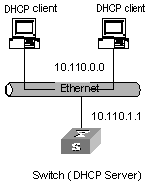
Figure 4-2 Network diagram for DHCP server
III. Configuration procedure
# Enter system view.
<H3C>system-view
# Create VLAN2.
[H3C]vlan 2
# Enter VLAN interface view and create Vlan-interface 2.
[H3C]interface Vlan-interface 2
# Assign an IP address to Vlan-interface 2.
[H3C-Vlan-interface2]ip address 10.110.1.1 255.255.0.0
# Specify to assign IP addresses in the interface address pool to DHCP clients.
[H3C-Vlan-interface2]dhcp select interface
# Specify to assign IP addresses in global address pool to DHCP clients (it is also the default configuration).
[H3C-Vlan-interface2]dhcp select global
Or execute the following command to revert to the default.
[H3C-Vlan-interface2]undo dhcp select
# Configure a global address pool.
[H3C]dhcp server ip-pool 1
[H3C-dhcp-1]network 10.110.0.0 mask 255.255.0.0
[H3C-dhcp-1]gateway-list 10.110.1.1
4.4 Configuring DHCP Relay
4.4.1 Introduction to DHCP Relay
This is a world where networks are ever-growing in both size and complexity, and the network configuration is getting more and more complex. As is often the case, the number of hosts in a network exceeds that of the available IP addresses, and position changes of hosts (when users carry their laptops from here to there, or move to a wireless network) require reassigned new IP addresses. Dynamic host configuration protocol (DHCP) is designed to accommodate this context. DHCP adopts client/server model, where DHCP clients send requests to the DHCP server dynamically and the DHCP server in turn returns corresponding configuration information according to the policies configured for it.
Early implementations of DHCP only work when DHCP clients and DHCP servers are in the same subnet. That is, they cannot work across networks. So, to implement dynamic host configuration, you must deploy at least one DHCP server in each subnet, and this is obviously uneconomical. DHCP Relay is designed to resolve this problem. Through a DHCP relay, DHCP clients in a LAN can communicate with DHCP servers in other subnets to acquire IP addresses. This enables DHCP clients of multiple networks to share a common DHCP server and thus enables you to save your cost and perform centralized administration. Figure 4-3 illustrates a typical DHCP Relay application.
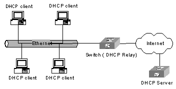
Figure 4-3 Network diagram for DHCP Relay
The dynamic host configuration procedure with DHCP relay is as follows:
l A DHCP client broadcasts configuration request packet in the local network when it starts up and initializes the configuration.
l If a DHCP server exists in the network, it processes the configuration request packet directly without the help of a DHCP Relay.
l If no DHCP server exists in the network, the network device serving as a DHCP Relay in the network appropriately processes the configuration request packet and forwards it to a specified DHCP server located in another network.
l After receiving the packet, the DHCP server generates configuration information accordingly and sends it to the DHCP client through the DHCP Relay to complete the dynamic configuration of the DHCP client.
Note that the entire configuration procedure may goes through multiples times of such interactions.
4.4.2 Configuring DHCP Relay
DHCP Relay configuration includes the following: The following text describes the DHCP Relay configuration tasks:
l Configuring a DHCP server for a VLAN interface
l Configure user address entries for a DHCP Relay
l Enable/Disable DHCP security on a VLAN interface
I. Configuring a DHCP server for a VLAN interface
You can execute the ip relay address command to configure the DHCP packet processing mode on VLAN interface as relay and a corresponding DHCP server for a VLAN interface.
Perform the following configuration in VLAN interface view.
Table 4-33 Configure a corresponding DHCP server for a VLAN interface
|
Operation |
Command |
|
Configure a corresponding DHCP server for current VLAN interface |
ip relay address ip-address |
|
Remove the DHCP server configured for current VLAN interface |
undo ip relay address { ip-address | all } |
No DHCP server is configured for a VLAN interface by default.
Note that when configuring a new DHCP server for a VLAN that already has a DHCP server configured for it, the newly configured one does not overwrite the existing ones. Both the new and the old ones are valid. You can configure up to 20 DHCP server addresses for a VLAN interface.
The IP address of the intended DHCP server for the DHCP relay feature cannot be IP address of the VLAN interface corresponding to the DHCP relay. Otherwise, the system gives the information such as “Can't set ip relay address as interface address on interface Vlan-interface 100!”.
II. Configure user address entries for a DHCP Relay
In a VLAN that has DHCP Relay configured, to enable a DHCP client using a legal fixed IP address to pass the address checking of the DHCP security feature, you must add a static address entry for the DHCP client. A static address entry indicates the relation between a fixed IP address and a MAC address.
Perform the following configuration in system view.
Table 4-34 Configure user address entries for DHCP relay
|
Operation |
Command |
|
Add a user address entry for DHCP relay |
dhcp relay security ip-address mac-address static |
|
Remove a user address entry for DHCP relay |
undo dhcp relay security ip-address |
& Note:
l The DHCP client applies for an IP address through the DHCP relay. When the packet from DHCP client passes the DHCP relay, the DHCP relay adds its primary IP address in the packet and forwards the packet to the DHCP server. When receiving the packet, DHCP server allocates an IP address in the same segment as the IP address added by the DHCP relay.
l Through the DHCP relay, the DHCP client only can obtain an IP address in the same segment as the primary IP address of the DHCP relay.
III. Enable/Disable DHCP security on a VLAN interface
If you enable the DHCP security feature on a VLAN interface, the switch performs user address checking on the VLAN interface to prevent unauthorized binding request. If you disable the DHCP security feature on a VLAN interface, the switch does not perform user address checking on the VLAN interface.
Perform the following configuration in VLAN interface view.
Table 4-35 Enable/disable DHCP security on a VLAN interface
|
Operation |
Command |
|
Enable DHCP security on a VLAN interface |
dhcp relay security address-check enable |
|
Disable DHCP security on a VLAN interface |
dhcp relay security address-check disable |
DHCP security is disabled on a VLAN interface by default.
![]() Caution:
Caution:
After the DHCP security feature is enabled on a VLAN interface, the client that has already obtained an IP address will lose its access right and has to apply for an IP address again. Therefore, it is recommended that the administrator should conduct this configuration before any user has obtained an IP address.
4.4.3 Displaying and Debugging DHCP Relay
After the above configuration, you can execute the display command in any view to display running information about DHCP Relay to verify your configuration.
Execute the debugging command in user view to debug DHCP Relay.
Table 4-36 Display and debug DHCP Relay
|
Operation |
Command |
|
Display information about the DHCP relay configured for VLAN interface |
display dhcp relay address { interface vlan-interface vlan-id | all } |
|
Display information about legal user address entries for DHCP relay |
display dhcprelay-security [ ip-address ] |
|
Enable debugging for DHCP Relay |
debugging dhcp relay { all| packet | error | event } |
|
Disable debugging for DHCP Relay |
undo debugging dhcp relay { all| packet | error | event } |
4.4.4 DHCP Relay Configuration Example
I. Network requirements
As shown in Figure 4-4, two DHCP clients located at the same network segment (10.110.0.0) are connected to a switch through a port in VLAN 2. The switch, acting as a DHCP relay, is supposed to forward DHCP packets between the two DHCP clients and the DHCP server with the IP address of 202.38.1.2.
II. Network diagram
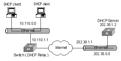
Figure 4-4 Network diagram for DHCP Relay
III. Configuration procedure
# Enter system view.
<H3C>system-view
# Create VLAN 2.
[H3C]vlan 2
# Create Vlan-interface 2 and enter VLAN interface view.
[H3C]interface Vlan-interface 2
# Assign an IP address to Vlan-interface 2.
[H3C-Vlan-interface2]ip address 10.110.1.1 255.255.0.0
# Specify to forward DHCP packets to a remote DHCP server.
[H3C-Vlan-interface2]dhcp select relay
# Configure the IP address of the DHCP server to which VLAN 2 sends DHCP packets.
[H3C-Vlan-interface2]ip relay address 202.38.1.2
& Note:
Besides the above configurations for DHCP Relay, you need to configure address pool on the DHCP server and make sure the DHCP server and the switch interface connecting the two DHCP clients is routing reachable with each other.
![]() Caution:
Caution:
Do not change or delete the IP address of the interface corresponding to the DHCP Relay; otherwise users will be unable to obtain IP addresses to access the Internet.
Chapter 5 DHCP Option 82 Configuration
5.1 DHCP Option 82 Overview
5.1.1 Introduction to Option 82 Support on DHCP Relay
Option 82 is the relay agent information option in the DHCP packets. When a DHCP client sends a DHCP request packet and the packet must be forwarded by a DHCP relay to reach a DHCP server, if Option 82 support is enabled on the DHCP relay, the DHCP relay adds Option 82 into the request packet. Option 82 can be composed of many sub-options, but Option 82 mentioned in this chapter only supports sub-option 1 and sub-option 2. Sub-option 1 defines the agent circuit ID (that is, Circuit ID), and sub-option 2 defines the agent remote ID (that is, Remote ID).
With Option 82, the information about the addresses of the DHCP clients and the DHCP relay devices can be recorded on the DHCP server. Using Option 82 together with other software can implement the DHCP allocation restrictions and the accounting function.
5.1.2 Concepts
I. Option
A DHCP packet has a field called options, which contains part of the lease information and the packet type. The options field is length-variable and consists of one option at least and 255 options at most.
II. Option 82
Option 82 is also called relay agent information option and is a part of the options field in a DHCP packet. Option 82 is defined in RFC 3046 before Option 255 and behind other options. You can define a minimum of one sub-option and a maximum of 255 sub-options for Option 82. At present, the commonly used sub-options in Option 82 include sub-option 1, sub-option 2 and sub-option 5.
III. Sub-option 1
Sub-option 1 belongs to Option 82 and defines the Circuit ID. Usually configured on the DHCP relay devices, it indicates that the forwarded packets will carry the VLAN ID and MAC address of the port of the switch that the DHCP client is connected to. Generally, sub-option 1 and sub-option 2 are used together to identify a DHCP client.
IV. Sub-option 2
Sub-option 2 also belongs to Option 82 and defines the Remote ID. Usually configured on the DHCP relay devices, it indicates that the forwarded packets will carry the MAC address of the relay device. Generally, sub-option 1 and sub-option 2 are used together to identify a DHCP client.
V. Sub-option 5
Sub-option 5 also belongs to Option 82 and defines the link selection. It contains an IP address which is added by the DHCP relay, so that the DHCP server can assign to the DHCP client an IP address that is in the same network segment with this address.
5.1.3 Option 82 Structure
I. Option 82 structure
There is a field named options in the DHCP packets. It can be null or contains at least one feature-specific option, such as Option 82 which may comprise multiple sub-options. Figure 5-1 illustrates the structure of Option 82.
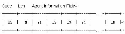
Figure 5-1 Option 82 structure
Code: Identifies the number of the relay agent information option. It is 82 in the packet, which represents Option 82. Option 82 is before Option 255 and is behind other options in RFC 3046.
Len: Indicates the length of the Agent Information Field.
Agent Information Field: Specifies the available sub-options.
II. Sub-option packet structure
Figure 5-2 shows the sub-option structure.
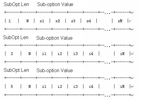
Figure 5-2 Sub-option structure
SubOpt: Indicates the number of the sub-option. Sub-options contained in this packet are sub-option 1, sub-option 2 and sub-option 5. They have the following meanings:
l Sub-option 1 defines the Circuit ID.
l Sub-option 2 defines the Remote ID.
l Sub-option 5 defines the Link Selection.
Len: Indicates the length of the Sub-option Value field.
Sub-option Value: Indicates the sub-option value. For example, the value for sub-option 1 is Circuit ID.
5.1.4 Related Protocols and Specifications
The protocols and specifications related to Option 82 support on DHCP relay are:
l RFC 2131 Dynamic Host Configuration Protocol
l RFC 3046 DHCP Relay Agent Information Option
5.1.5 Working Mechanism of Option 82 Support on DHCP Relay
The process for a DHCP client to acquire an IP address from a DHCP server through a DHCP relay is the same as that for a DHCP client to acquire an IP address directly from the DHCP server in the same network segment. Both the processes have four phases: discovery, offer, selection and acknowledgement. For the details, refer to 0“
DHCP Configuration”. The following only introduces the working mechanism of Option 82 support on DHCP relay.
1) A DHCP client broadcasts a request packet during initialization.
2) If a DHCP server exists in the local network, the DHCP client acquires an IP address from this server directly. If not, the broadcast packet is processed by the DHCP relay device that is connected to the local network. The DHCP relay device will check whether Option 82 exists in the packet.
3) If Option 82 exists in the packet, the relay processes the packet according to the configured strategy. The relay may drop the packet, replace the original Option 82 with its own Option 82, or keep the original Option 82 unchanged. Then, the relay forwards the packet (if not dropped) to a DHCP server.
4) If Option 82 does not exist in the request packet, the DHCP relay device adds Option 82 into the packet and then forwards it to a DHCP server. In this way, the packet contains the MAC address and VLAN ID of the port of the switch that the DHCP client is connected to, and the MAC address of the DHCP relay itself.
5) After receiving the DHCP request packet forwarded by the DHCP relay, the DHCP server records the information carried by the option in the packet. Then, the DHCP server sends to the DHCP relay a response packet which carries the DHCP configuration information and Option 82 information.
6) After receiving the response packet sent by the DHCP server, the DHCP relay strips Option 82 information in the packet. Then, it forwards the packet that carries the DHCP configuration information to the DHCP client.
& Note:
The request packets sent by a DHCP client fall into two types: DHCP_DISCOVER packets and DHCP_REQUEST packets. The DHCP relay device adds Option 82 into both types of request packets. This is because that the DHCP servers from different manufacturers process the request packets in different ways. Some of them process Option 82 in the DHCP_DISCOVER packets, while others process Option 82 in the DHCP_REQUEST packets.
5.2 Configuring Option 82 Supply on DHCP Relay
5.2.1 Prerequisites
Before enabling Option 82 support on DHCP relay, you should configure:
l The network parameters and the relay function on the DHCP relay
l The network parameters, the parameters related to the allocation strategy such as the address pools and the address allocation lease on the DHCP server.
In addition, you should make proper configuration to ensure that the DHCP relay and the DHCP server devices are reachable to each other.
For detailed configurations, refer toChapter 4 “DHCP Configuration” of this manual.
5.2.2 Enabling Option 82 Support on DHCP Relay
The configurations here can only be performed on the network devices where the DHCP relay function is enabled.
Table 5-1 Enable Option 82 support on DHCP relay
|
Operation |
Command |
Remarks |
|
Enter system view |
system-view |
- |
|
Enable Option 82 support on DHCP relay |
dhcp relay information enable |
Required |
|
Configure the strategy for the DHCP relay to process the request packets that carry Option 82 |
dhcp relay information strategy { drop | keep | replace } |
Optional By default, the DHCP relay adopts the strategy replace to process the request packets that carry Option 82. That is, the DHCP relay replaces the original Option 82 in the packets with its own Option 82. |
5.3 Configuration Example
5.3.1 Option 82 Support on DHCP Relay Configuration Example
I. Network requirements
Two DHCP clients are on 10.110.0.0, and they acquire IP addresses from the DHCP server through a DHCP relay device. The DHCP relay function is enabled on a VLAN interface of the switch serving as the DHCP relay. Option 82 support is enabled on the DHCP relay.
II. Network diagram
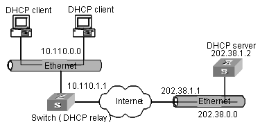
Figure 5-3 Network diagram for Option 82 support on DHCP relay configuration
III. Configuration procedure
Suppose the DHCP relay and the DHCP server is reachable to each other. The following only introduces the configuration on the switch which serves as the DHCP relay.
# Enable the DHCP service.
<H3C> system-view
[H3C] dhcp enable
# Enter the view of the interface on which the DHCP relay function will be enabled. Configure an IP address and a subnet mask for the interface so that it belongs to the same network segment with the DHCP client.
[H3C] interface vlan-interface 100
[H3C-vlan-interface 100] ip address 10.110.1.1 255.255.0.0
# Enable the DHCP relay function on the interface, and configure an IP address for the DHCP relay function (this address specifies the location of the DHCP server for this interface). Enable Option 82 support on DHCP relay and specify the strategy to keep.
[H3C] interface vlan-interface 100
[H3C-vlan-interface 100 ] dhcp select relay
[H3C-vlan-interface 100] ip relay address 202.38.1.2
[H3C-vlan-interface 100 ] quit
[H3C] dhcp relay information enable
[H3C] dhcp relay information strategy keep
The configuration of the DHCP server is omitted here.
Chapter 6 DNS Configuration
6.1 Introduction to DNS
Used in the TCP/IP application, Domain Name System (DNS) is a distributed database which provides the translation between domain name and the IP address. In this way, the user can use domain names that are easy to memorize and meaningful, and never needs to keep obscure IP addresses in mind.
There are two kinds of domain name resolutions: static domain name resolution and dynamic domain name resolution, which supplement each other in real application. On resolving a domain name, use the static resolution first. If it fails, use the dynamic resolution method. You can put some common domain names into the static domain name resolution table to raise the domain name resolution efficiency greatly.
6.1.1 Static Domain Name Resolution
Static domain resolution is to establish maps between domain name and the IP address manually. When you perform some applications using domain names, the system can obtain the IP address of the specified domain name by searching the static domain name resolution table.
6.1.2 Dynamic Domain Name Resolution
Dynamic domain name resolution is implemented by inquiring the domain name server. As a DNS client, the switch sends an inquiry request to the domain name server, and the domain name server searches the related IP address of the domain name in its own database and sends it back to the switch. If the domain name server judges that the domain name does not belong to the local domain, it forwards the request to the upper level domain name resolution server till the resolution is finished.
Dynamic domain name resolution supports the buffer function. It stores each successful domain name/IP address mapping that is resolved dynamically in the dynamic domain name buffer. When the same domain name is searched next time, it can be read directly from the buffer, without requesting the domain name server. The aged mapping in the buffer is deleted after a certain period of time to ensure the updated contents can be got from the domain name server timely. The aging time is set by the domain name server and obtained by the switch from the protocol packet.
Dynamic domain name resolution supports the domain name suffix list function. You can set some domain name suffixes beforehand and input part of the domain name field during the domain name resolution, then the system adds different suffixes to the input domain name automatically for resolution. For example, if a user wants to search the domain name “h3c.com”, he can configure the “com” in the suffix list and input “H3C”. Then the system connects the input domain name with the suffix into “h3c.com” automatically to search. When the domain name suffix is used, if the input domain name does not include “.”, like “H3C”, the system regards it as a host name and add a domain name suffix to search. After all the domain names are failed to be searched out in this way, the system finally searches with the primarily input domain name. If the input domain name does include “.”, like “www.H3C”, the system searches with it directly. The system adds each suffix to search one by one only after the search fails. If the input domain name contains a “.” in the final position, like “h3c.com.”, it indicates that the domain name suffix needs not to be added. The system removes the last “.” from the input domain name and search with the remaining part. Succeeded or not, the system returns to the originally input domain name. Put it more specifically, if the last character of the input domain name is “.”, the system only searches according to characters before the “.” rather than matches the domain name. In this sense, the last “.” is also called “search terminator”.
6.2 Configuring Static Domain Name Resolution
You can use this command to map the host name to the host IP address. When you use applications like Telnet, you can use the host name directly, and the system translates it into the IP address, rather than the obscure IP address.
Perform the following configuration in system view.
Table 6-1 Configure host name and the corresponding IP address
|
Operation |
Command |
|
Configure host name and the corresponding IP address |
ip host hostname ip-address |
|
Cancel host name and the corresponding IP address |
undo ip host hostname [ ip-address ] |
Each host can have only one IP address. If you configure a host name more than once, then the IP address configured at last is effective.
6.3 Configuring Dynamic Domain Name Resolution
Dynamic domain name resolution configuration includes:
l Enable/Disable Static Domain Name Resolution
l Configure the IP Address of Domain Name Server
l Configure Domain Name Suffix
6.3.1 Enable/Disable Static Domain Name Resolution
Perform the following configuration in system view.
Table 6-2 Enable/disable dynamic domain name resolution
|
Operation |
Command |
|
Enable dynamic domain name resolution |
dns resolve |
|
Disable dynamic domain name resolution |
undo dns resolve |
By default, dynamic domain name resolution is disabled.
6.3.2 Configure the IP Address of Domain Name Server
Perform the following configuration in system view.
Table 6-3 Configure the IP address of the domain name sever
|
Operation |
Command |
|
Configure the IP address of the domain name sever |
dns server ip-address |
|
Delete the IP address of the domain name sever |
undo dns server [ ip-address ] |
6.3.3 Configure Domain Name Suffix
You can use the following command to configure domain name suffix list. By configuring this, you can just input part of the domain name and the system automatically adds the preconfigured suffix to perform the resolution. The system supports up to 10 domain name suffixes.
Perform the following configuration in system view.
Table 6-4 Configure domain name suffix
|
Operation |
Command |
|
Configure domain name suffix |
dns domain domain-name |
|
Delete domain name suffix |
undo dns domain [ domain-name ] |
6.4 Displaying and Debugging Domain Name Resolution
After the above configuration, you can execute the display command in any view to view the running states of the domain name resolution, and verify the configuration results through the displayed information.
Execute the reset command in user view to clear the dynamic domain name buffer. Execute the debugging command to debug the domain name resolution.
Table 6-5 Display and debug the domain name resolution
|
Operation |
Command |
|
Display the static domain name resolution table |
display ip host |
|
Display the information on domain name sever |
display dns server |
|
Display the information on domain name suffix list |
display dns domain |
|
Display the information on the dynamic domain name buffer |
display dns dynamic-host |
|
Clear dynamic domain name buffer |
reset dns dynamic-host |
|
Enable the debugging for the domain name resolution |
debugging dns |
|
Disable the debugging for the domain name resolution |
undo debugging dns |
6.5 DNS Configuration Example
I. Network requirements
As the client, the switch uses dynamic domain name resolution. The IP address of the domain name server is 172.16.1.1. The configured suffix of the domain name is “com”. There is a route between the switch and the server.
II. Network diagram
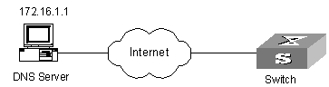
Figure 6-1 Network diagram for DNS client
III. Configuraiton procedure
# Enable dynamic domain name resolution
[H3C] dns resolve
# Configure the IP address of the domain name server to 172.16.1.1.
[H3C] dns server 172.16.1.1
# Configure the domain name suffix as com.
[H3C] dns domain com
# Ping a host with the specified domain name.
[H3C] ping ftp
Trying DNS server (172.16.1.1)
PING ftp.com (200.200.200.200): 56 data bytes, press CTRL_C to break
Reply from 200.200.200.200: bytes=56 Sequence=1 ttl=128 time=2 ms
Reply from 200.200.200.200: bytes=56 Sequence=2 ttl=128 time=2 ms
Reply from 200.200.200.200: bytes=56 Sequence=3 ttl=128 time=2 ms
Reply from 200.200.200.200: bytes=56 Sequence=4 ttl=128 time=2 ms
Reply from 200.200.200.200: bytes=56 Sequence=5 ttl=128 time=2 ms
--- ftp.com ping statistics ---
5 packet(s) transmitted
5 packet(s) received
0.00% packet loss
round-trip min/avg/max = 2/2/2 ms
The routing configuration between the switch and the domain name sever is omitted here, and refer to the related chapter for the configuration.
6.6 Troubleshooting Domain Name Resolution Configuration
Fault: Domain name resolution fails.
Troubleshoot: Perform the following procedures:
l Check whether the domain name resolution function is enabled.
l Check whether the IP address of the domain name sever is correctly configured.
l Check whether there is a correct route between the domain name sever and the switch.
l Check whether there is network connection failure, such as network cable break, loose connection, and so on.
Chapter 7 IP Performance Configuration
7.1 Configuring IP Performance
IP performance configuration includes:
7.1.1 Configuring TCP Attributes
TCP attributes that can be configured include:
l synwait timer: When sending the syn packets, TCP starts the synwait timer. If response packets are not received before synwait timeout, the TCP connection is terminated. The timeout of synwait timer ranges from 2 to 600 seconds and it is 75 seconds by default.
l finwait timer: When the TCP connection state turns from FIN_WAIT_1 to FIN_WAIT_2, finwait timer is started. If FIN packets are not received before finwait timer timeout, the TCP connection is terminated. The timeout of finwait timer ranges from 76 to 3600 seconds and it is 675 seconds by default.
l The receiving/sending buffer size of the connection-oriented socket is in the range from 1 to 32 KB and is 8 KB by default.
Perform the following configuration in System view.
Table 7-1 Configure TCP attributes
|
Operation |
Command |
|
Configure timeout time for the synwait timer in TCP |
tcp timer syn-timeout time-value |
|
Restore the default timeout time of the synwait timer |
undo tcp timer syn-timeout |
|
Configure timeout time for the FIN_WAIT_2 timer in TCP |
tcp timer fin-timeout time-value |
|
Restore the default timeout time of the FIN_WAIT_2 timer |
undo tcp timer fin-timeout |
|
Configure the socket receiving/sending buffer size of TCP |
tcp window window-size |
|
Restore the socket receiving/sending buffer size of TCP to default value |
undo tcp window |
7.2 Displaying and Debugging IP Performance
Execute the debugging command to debug IP performance.
Table 7-2 Display and debug IP performance
|
Operation |
Command |
|
Display TCP connection state |
display tcp status |
|
Display TCP connection statistics data |
display tcp statistics |
|
Display UDP statistics information |
display udp statistics |
|
Display IP statistics information |
display ip statistics |
|
Display ICMP statistics information |
display icmp statistics |
|
Display the current socket information of the system |
display ip socket [ socktype sock-type ] [ task-id socket-id ] |
|
Display the summary of the Forwarding Information Base (FIB) |
display fib |
|
Display the FIB entries matching the destination IP address (range) |
display fib [ ip-address1 { mask1 | mask-length1 } [ ip-address2 { mask2 | mask-length2 } | longer ] | longer ] |
|
Display the FIB entries matching a specific ACL |
display fib acl { number | name } |
|
Display the FIB entries which are output from the buffer according to regular expression and related to the specific character string |
display fib | { { begin | include | exclude } text } |
|
Display the FIB entries matching the specific prefix list |
display fib ip-prefix listname |
|
Display the total number of FIB entries |
display fib statistics |
|
Reset IP statistics information |
reset ip statistics |
|
Reset TCP statistics information |
reset tcp statistics |
|
Reset UDP statistics information |
reset udp statistics |
|
Enable the debugging of IP packets |
debugging ip packet [ acl acl-number ] |
|
Disable the debugging of IP packets |
undo debugging ip packet |
|
Enable the debugging of ICMP packets |
debugging ip icmp |
|
Disable the debugging of ICMP packets |
undo debugging ip icmp |
|
Enable the debugging of UDP connections |
debugging udp packet [ task-id socket-id ] |
|
Disable the debugging of UDP connections |
undo debugging udp packet [ task-id socket-id ] |
|
Enable the debugging of TCP connections |
debugging tcp packet [ task-id socket-id ] |
|
Disable the debugging of TCP connections |
undo debugging tcp packet [ task-id socket-id ] |
|
Enable the debugging of TCP events |
debugging tcp event [ task-id socket-id ] |
|
Disable the debugging of TCP events |
undo debugging tcp event [ task-id socket-id ] |
|
Enable the debugging of the MD5 authentication |
debugging tcp md5 |
|
Disable the debugging of the MD5 authentication |
undo debugging md5 |
7.3 Troubleshooting IP Performance
Fault: IP layer protocol works normally but TCP and UDP cannot work normally.
Troubleshoot: In the event of such a fault, you can enable the corresponding debugging information output to view the debugging information.
l Use the display command to view the running information of IP performance and make sure that the PCs used by the user is running normally.
l Use the terminal debugging command to output the debugging information to the console.
l Use the debugging udp packet command to enable the UDP debugging to trace the UDP packet.
The following are the UDP packet formats:
UDP output packet:
Source IP address:202.38.160.1
Source port:1024
Destination IP Address 202.38.160.1
Destination port: 4296
task = ROUT(15)
socketid = 6,
src = 192.168.1.1:520,
dst = 255.255.255.255:520,
datalen = 24
l Use the debugging tcp packet command to enable the TCP debugging to trace the TCP packets.
Operations include:
<H3C> terminal debugging
<H3C> debugging tcp packet
Then the TCP packets received or sent can be checked in real time. Specific packet formats include:
TCP output packet:
Source IP address:202.38.160.1
Source port:1024
Destination IP Address 202.38.160.1
Destination port: 4296
Sequence number :4185089
Ack number: 0
Flag :SYN
Packet length :60
Data offset: 10
task = ROUT(15)
socketid = 5
state = Established
src = 172.16.1.2
Source port:1025
dst = 172.16.1.1
Destination port: 4296
seq = 1921836502
ack = 4192768493
flag = ACK
window = 16079