- Table of Contents
-
- H3C S9500 Series Routing Switches Operation Manual-(V1.01)
- 00-1Cover
- 01-Getting Started Operation
- 02-Port Operation
- 03-VLAN-QinQ Operation
- 04-Network Protocol Operation
- 05-Routing Protocol Operation
- 06-Multicast Protocol Operation
- 07-QACL Operation
- 08-MPLS Operation
- 09-STP Operation
- 10-Security Operation
- 11-Reliability Operation
- 12-System Management Operation
- 13-PoE Operation
- 14-NAT-URPF-VPLS Operation
- 15-Integrated Management Operation
- 16-Appendix
- Related Documents
-
| Title | Size | Download |
|---|---|---|
| 08-MPLS Operation | 1 MB |
1.3.2 Forwarding Labeled Packets
1.3.4 LSP Tunnel and Hierarchy
1.3.5 MPLS and Other Protocols (Routing Protocols)
1.3.6 MPLS Application (MPLS-based VPN)
Chapter 2 MPLS Basic Capability Configuration
2.1 MPLS Basic Capability Overview
2.2.2 Enabling MPLS and Entering MPLS View
2.2.3 Configuring the Topology-Driven LSP Setup Policy
2.3.2 Enabling LDP on VLAN interface
2.3.3 Configuring Remote-Peer for Extended Discovery Mode
2.3.4 Configuring session parameters
2.3.5 Configuring LDP Loop Detection Control
2.3.6 Configuring LDP Authentication Mode Between Every Two Routers
2.4 Displaying and Debugging MPLS Basic Capability
2.4.1 Displaying and Debugging MPLS
2.4.2 Displaying and Debugging LDP
2.5 Typical MPLS Configuration Example
2.6 Troubleshooting MPLS Configuration
Chapter 3 BGP/MPLS VPN Configuration
3.1.2 BGP/MPLS VPN Implementation
3.1.3 Nested BGP/MPLS VPN Implementation
3.1.4 Hierarchical BGP/MPLS VPN Implementation
3.1.5 Introduction to OSPF Multi-instance
3.1.6 Introduction to Multi-Role Host
3.2 BGP/MPLS VPN Configuration
3.2.1 Configuring Various Kinds of Routers
3.3 Displaying and Debugging BGP/MPLS VPN
3.4 Typical BGP/MPLS VPN Configuration Example
3.4.1 Integrated BGP/MPLS VPN Configuration Example
3.4.2 Extranet Configuration Example
3.4.3 Hub&Spoke Configuration Example
3.4.4 CE Dual-home Configuration Example
3.4.5 Cross-domain BGP/MPLS VPN Configuration Example
3.4.6 Cross-Domain BGP/MPLS VPN Configuration Example — Option C
3.4.7 Hierarchical BGP/MPLS VPN Configuration Example
3.4.8 OSPF Multi-instance Sham-link Configuration Example
3.4.9 Nested BGP/MPLS VPN Configuration Example
3.4.10 OSPF Multi-instance CE Configuration Example
3.4.11 Multi-Role Host Configuration Example
4.1.1 Introduction to MPLS L2VP
4.2 CCC MPLS L2VPN Configuration
4.2.1 Configuring CCC MPLS L2VPN
4.2.2 CCC MPLS L2VPN Configuration Example
4.3 Martini MPLS L2VPN Configuration
4.3.1 Configuring Martini MPLS L2VPN
4.3.2 Martini MPLS L2VPN Configuration Example
4.4 Kompella MPLS L2VPN Configuration
4.4.1 Configuring Kompella MPLS L2VPN
4.4.2 Kompella MPLS L2VPN Configuration Example
4.5 Displaying and Debugging MPLS L2VPN
4.6 Troubleshooting MPLS L2VPN
Chapter 5 Card Intermixing for MPLS Support
5.1.1 Introduction to Card Intermixing
5.1.2 Card Intermixing Mechanism
5.2 Restrictions in Intermixing Networking
5.2.1 Rules of Intermixing Configuration
5.2.2 Restrictions in Card Intermixing
5.3 Introduction to intermixing configuration task
5.3.1 Configuring Routing Protocols
5.3.2 Configuring Basic Capability of MPLS
5.3.4 Configuring flow template and ACL rules
5.3.5 Applying Flow Template and Redirection in Port Mode
5.3.6 Typical Networking Example
5.4 Restrictions in Networking of Various MPLS Cards
5.4.1 Exclusively non-MPLS Cards
5.4.3 Exclusively VPLS Service Cards
5.4.4 Combination of One MPLS Card and Multiple non-MPLS Cards
5.4.5 Combination of Multiple MPLS cards and Multiple non-MPLS Cards
5.4.6 Combination of One VPLS Card and Multiple non-MPLS Cards
5.4.7 Combination of One VPLS card and Multiple MPLS Cards
5.4.8 Combination of One VPLS card, One MPLS Card and Multiple non-MPLS Cards
Chapter 1 MPLS Architecture
& Note:
The H3C S9500 Series Routing Switches (hereinafter referred to as S9500 series) running MPLS can serve as routers. Routers mentioned in this manual can be either a router in common sense, or a layer 3 Ethernet switch running MPLS.
For S9500 switches, only the interface boards with the suffixes C, CA and CB and VPLS service processor cards support the MPLS function. To enable MPLS function on the S9500 switches, you must select the interface cards that support MPLS or VPLS service processor cards. The suffix of a board can be identified through the silkscreen on the upper right corner of the front panel of the card. For example, the silkscreen on LSB1GP12B0 card is GP12B, so the suffix of the card is B.
1.1 MPLS Overview
MPLS (Multiprotocol Label Switching) encapsulates network layer packets with short and fixed-length labels. As the name implies, it supports multiple protocols, such as IP, IPv6, and IPX. And it allows a device to make forwarding decision based on the labels attached to the received packets without going through the complex routing table lookup procedures with IP. MPLS brings together the advantages of the connectionless control with IP and the connection-oriented forwarding with ATM. In addition to the support from IP routing and control protocols, its powerful and flexible routing functions allows it to accommodate to various emerging applications.
MPLS was initially proposed to accelerate the packet forwarding on routers, but it has been widely used in Traffic Engineering (TE), Virtual Private Network (VPN), and other aspects, and is becoming one of the most important standards on large scale IP networks.
1.2 MPLS Basic Concepts
1.2.1 FEC
Forwarding Equivalence Class (FEC) is an important concept in MPLS. MPLS is actually a kind of classify-and-forward technology. It categorizes packets with the same forwarding strategy (same destination addresses, same forwarding routes and same QoS levels) into one class, which is called a FEC. Generally, the FEC classification is based on network layer address. Packets of the same FEC are processed in the same way in MPLS network.
1.2.2 Label
I. Label definition
A label is a locally significant short identifier with fixed length, which is used to identify a FEC. When reaching at MPLS network ingress, packets are divided into different FECs, based on their FECs, different labels are encapsulated into the packets. Later forwarding is based on these labels.
II. Label structure
The structure of the label is shown in Figure 1-1.
![]()
Label is located between the link layer header and the network layer packet, with the length of four bytes. A label contains four fields:
Label: label value, 20 bits.
Exp: three bits, reserved, used for COS.
S: one bit, MPLS supports hierarchical label structure, namely multi-layer label. Value 1 refers to the label of bottom layer.
TTL: eight bits, with the same meaning as TTL in IP packet.
III. Label operations
1) Label mapping
There are two types of label mapping: label mapping at ingress routers, and label mapping in MPLS domain.
The first type of mapping is implemented at Ingress label switching routers (LSR). The Ingress LSRs group the incoming packets into multiple FECs based on certain principles, and then map corresponding labels to these FECs and record the mapping results into the label information base (LIB). In simple words, label mapping is to assign a label to a FEC.
The second type is also called incoming label mapping (ILM), that is, to map each input label to a series of next hop label forwarding entries (NHLFE). The packets are forwarded along the paths based on the mapping results.
2) Label encapsulation
Figure 1-2 illustrates label encapsulation in different media:
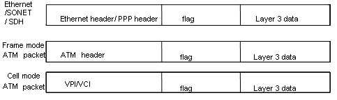
Figure 1-2 Label position in packet
In Ethernet packets and PPP packets, label stack lies between layer 2 header and layer 3 data, acting like a shim. In ATM cell mode packets, VPI/VCI is used as the label.
3) Label assignment and distribution
Label distribution refers to the process of creating a corresponding label switching path (LSP) for a FEC.
In the MPLS architecture, the decision to bind a particular label to a particular FEC is made by downstream LSR; after making the decision, the downstream LSR notifies the upstream LSR. That is to say, the label is assigned by the downstream LSR, and the assigned label is distributed from downstream to upstream.
Two label distribution modes are available in MPLS: downstream unsolicited (DU) mode and downstream on demand (DoD) mode.
l For a specific FEC, if LSR originates label assignment and distribution even without receiving label request message from upstream, it is in DU mode.
l For a specific FEC, if LSR begins label assignment and distribution only after receiving label request message from upstream, it is in DoD mode.
The upstream and downstream which have adjacency relation in-label distribution should reach agreement on label distribution mode.
To distribute labels to its peer, the LSR can use Label Distribution Protocol (LDP) messages or make the labels carried on other routing protocol messages.
& Note:
Upstream and downstream are just on a relative basis: For a packet forwarding process, the transmit router serves as upstream LSR and receive router serves as downstream LSR. Currently, the S9500 series adopt the DU label distribution mode.
4) Label assignment control mode
There are two modes to control the assignment and distribution of labels: independent mode and ordered mode.
In independent control mode, each LSR can send label mapping messages to the LSRs it connects to at anytime.
In ordered control mode, a LSR can send label mapping messages to upstream only when it receives a specific label mapping messages of the next hop of a FEC or the LSR serves as LSP (Label Switching Path) egress node.
& Note:
Currently, the S9500 series adopt the ordered label control mode.
5) Label retention mode
There are two label-retention modes: liberal label retention mode and conservative label retention mode.
Suppose there are two LSRs: Ru and Rd. For a specific FEC, if LSR Ru has received the label binding from LSR Rd, in case Rd is not the next hop of Ru and Ru saves this binding, then it is the liberal label retention. And if Ru discards this binding, then it is the conservative label retention mode.
In case it is required that LSR is capable of adapting route variation rapidly, you can use the liberal label retention mode. In case it is required that a few labels are saved in LSR, you can use the conservative label retention mode.
& Note:
Currently, the S9500 series adopt the liberal label retention mode.
1.2.3 LDP
Label distribution protocol (LDP) is the signaling control protocol in MPLS, which controls binding labels and FECs between LSRs and coordinates a series of procedures between LSRs.
1.3 MPLS Architecture
1.3.1 MPLS Network Structure
The basic composing unit of MPLS network is LSR (Label Switching Router). It runs MPLS control protocol and L3 routing protocol, exchanges routing messages with other LSRs and create the routing table, maps FECs with IP packet headers, binds FECs with labels, distributes label binding messages, establishes and maintains label forwarding table.
The network consisting of LSRs is called MPLS domain. The LSR that is located at the edge of the domain is called edge LSR (LER, Labeled Edge Router). It connects an MPLS domain with a non-MPLS domain or with another MPLS domain, classifies packets, distributes labels (as ingress LER) and distracts labels (as egress LER). The ingress LER is termed as ingress and egress LER as egress.
The LSR that is located inside the domain is called core LSR, which provides functions such as label swapping and label distribution. The labeled packets are transmitted along the LSP (Label Switched Path) composed of a series of LSRs.
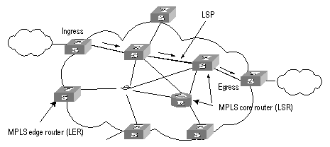
Figure 1-3 MPLS basic principle
1.3.2 Forwarding Labeled Packets
At the ingress, the packets entering the network are classified into FECs according to their characteristics. Usually, packets are classified into FECs according to the IP address prefix or host address. Packets in the same FEC pass through the same path (that is, LSP) in MPLS area. LSR assigns a short label of fixed length for the incoming FEC packet, and then forwards it through the corresponding interface.
On the LSR along the LSP, the mapping table of the import/export labels has been established (the element of this table is referred to as Next Hop Label Forwarding Entry (NHLFE)). When the labeled packet arrives, LSR only needs to find the corresponding NHLFE from the table according to the label and replace the original label with a new one, and then forwards the labeled packet. This process is called Incoming Label Map (ILM).
At the ingress, MPLS specifies a FEC for a specific packet, and the following routers only need to forward the packet by label switching, therefore this method is much simpler than general network layer forwarding and increases the forwarding speed.
1.3.3 Establishing LSP
Actually, the establishment of LSP refers to the process of binding FEC with the label, and then advertising this binding to the adjacent LSR on LSP. This process is implemented through LDP, which regulates the message in interactive processing and message structure between LSRs as well as routing mode.
I. LDP working process
Through sending Hello message periodically, an LSR finds its neighbor and then establish LDP session with the newly discovered adjacent LSR. By LDP session, the adjacent LSRs advertise such information as label switching mode, label space, session Keepalive timer value to each other. LDP session is a TCP connection, which needs to be maintained through LDP message. In case there is not any other LDP message during the time period specified by the session Keepalive timer value, and then it is necessary to send session Keepalive message to maintain the existence of LDP session. Figure 1-4 illustrates the diagram of LDP label distribution.
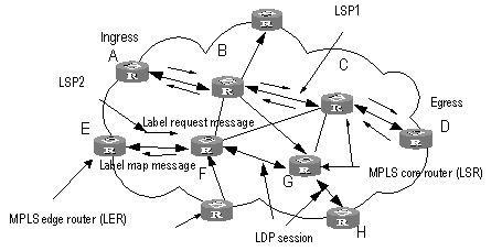
Figure 1-4 Label distribution process
For the label distribution mentioned previously, there are two modes: DoD and DU. The main difference between these two modes is that the label mapping messages are distributed actively or passively.
In DoD mode, the label is distributed in this way: the upstream LSR sends label request message (containing FEC descriptive information) to the downstream LSR, and the downstream LSR distributes label for this FEC, and then it sends the bound label back to the upstream LSR through label map message. The time when the downstream LSR feeds back the label map message depends on whether this LSR uses independent label control mode or sequential label control mode. When the sequential label control mode is used by the downstream LSR, the label map message is sent back to its upstream LSR if only it has received the label map message from its downstream LSR. And when the independent label control mode is used by the downstream LSR, then it will send label map message to its upstream LSR immediately, no matter whether it has received the returned label map message from its downstream LSR. Usually, the upstream LSR selects the downstream LSR according to the information in its routing table. In Figure 1-4, LSRs on the way along LSP1 use the sequential label control mode, and the LSR F on LSP2 uses independent label control mode.
In DU mode, the label is distributed in the following way: when LDP session is established successfully, the downstream LSR will actively distribute label map message to its upstream LSR. And the upstream LSR saves the label map information and processes the received label map information according to the routing table.
II. LSP loop control
While establishing LSP in MPLS domain, it is also necessary to prevent the presence of path loop. Then, such two methods as maximum hop count and path vector can be used.
The maximum hop count method refers to that the hop-count information is contained in the message bound with the forwarding label, and the value pluses one for each hop. When the value exceeds the threshold value, it is considered that a loop presents, and the process for establishing LSP is terminated.
The path vector method refers to that the path information is recorded in the message bound with the forwarding label, and, for every hop, the corresponding router checks if its ID is contained in this record. If not, the router adds its ID into the record; and if yes, it indicates that a loop presents and the process for establishing LSP is terminated.
1.3.4 LSP Tunnel and Hierarchy
I. LSP tunnel
MPLS supports LSP tunnel technology. On an LSP path, LSR Ru and LSR Rd are both the upstream and the downstream for each other. However, the path between LSR Ru and LSR Rd may not be part of the path provided by routing protocol. MPLS allows establishing a new LSP path <Ru R1...Rn Rd> between LSR Ru and LSR Rd, and LSR Ru and LSR Rd are respectively the starting point and ending point of this LSP. The LSP between LSR Ru and LSR Rd is referred to as the LSP tunnel, which avoids the traditional encapsulated tunnel on the network layer. If the route along which the tunnel passes and the route obtained hop by hop from routing protocol is consistent, this tunnel is called hop-by-hop routing tunnel. And if the two routes are not consistent, then the tunnel of this type is called explicit routing tunnel.
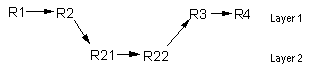
As shown in Figure 1-5, LSP <R2 R21 R22 R3> is a tunnel between R2 and R3.
II. Multi-layer label stack
In MPLS, a packet may carry multiple labels which are in the form of stack. Operations to the stack follow the “last in first out” principle and it is always the labels at the top of the stack that decide how to forward packets. Pushing label indicates to add a label into a outgoing packet, then the depth of the label stack is the former one plus 1, and the current label of the packet changes to the newly added one; popping a label indicates to remove a label form a packet, then the depth of the packet is the former one minus 1, and the current label of the packet changes to the label of its underlayer.
Multiple-layer label stack is used in LSP tunnel. When a packet travels in LSP tunnel, there will be multiple layers for the label of the packet. Then, at the ingress and egress of each tunnel, it is necessary to implement pushing and popping operation for the label stack. For each pushing operation, the label will be added with one layer. And there is no depth limitation for the label stack from MPLS.
The labels are organized according to the principle of “last in first out” in the label stack, and MPLS processes the labels beginning from the top of the stack.
If the depth of the label stack for a packet is m, it indicates that the label at the bottom of that stack is level 1 label, and the label at the top of the stack is level m label. A packet with no label can be regarded as a packet with empty label stack, that is, the depth of its label stack is 0.
1.3.5 MPLS and Other Protocols (Routing Protocols)
When LDP establishes LSP in hop-by-hop mode, the next hop is determined by using the information, which is usually collected by such routing protocols as IGP, BGP in each LSR route forwarding table, on the way. However, LDP just uses the routing information indirectly, rather than associates with various routing protocols directly.
On the other hand, although LDP is the special protocol for implementing label distribution, it is not the sole protocol for label distribution. The existing protocols such as BGP, RSVP, after being extended, can also support MPLS label distribution. For some MPLS applications, it is also necessary to extend some routing protocols. For example, the application of MPLS VPN requires extending the BGP protocol, thus the BGP protocol can propagate VPN routing information.
1.3.6 MPLS Application (MPLS-based VPN)
To transmit data stream of private network on public network, traditional VPN uses tunnel protocols like GRE, L2TP, and PPTP. LSP itself is a tunnel on public network, so there are obvious advantages to implement VPN by MPLS. MPLS VPN connects the geographically different branches of private network by using LSP, forming a united network. MPLS VPN also supports the interconnection between different VPNs.
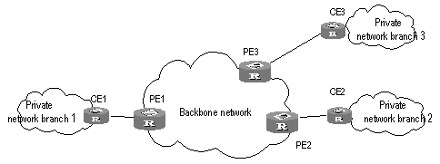
The basic structure of MPLS-based VPN is shown in Figure 1-6. CE is the customer edge device, and it may either be a router or a switch, or perhaps a host. PE is a service provider edge router, which is located on the backbone network. PE is responsible for the management of VPN customers, establishing LSP connection between various PEs, route allocation among different branches of the same VPN customer.
Usually the route allocation between PEs is implemented by using extended BGP. MPLS VPN supports the IP address multiplexing between different branches and the interconnection between different VPNs. Compared with traditional route, it is necessary to add branch and VPN identifier information in VPN route. So, it is necessary to extend BGP so as to carry VPN routing information.
Chapter 2 MPLS Basic Capability Configuration
2.1 MPLS Basic Capability Overview
Basic MPLS forwarding functions includes LDP session establishment and LSP path maintenance.
The typical configuration procedure for enabling basic MPLS functions on a routing switch is as follows:
1) Configure LSR ID
2) Enable MPLS
3) Enable LDP
4) Enter VLAN interface view and enable MPLS and LDP on the interface
Then the routing switch can provide MPLS forwarding and LDP signaling functions.
If you want to modify the default parameters or enable some special functions, for example, manually creating LSP or explicit route, you can configure according to the methods in configuration list. For some complicated functions, configuration combination may be required.
2.2 MPLS Configuration
The following sections describe the required configuration tasks for MPLS basic capability:
l Enabling MPLS and Entering MPLS View
The following sections describe the optional configuration tasks for MPLS basic capability:
l Configuring the Topology-Driven LSP Setup Policy
2.2.1 Defining MPLS LSR ID
Before configuring any other MPLS command, it is necessary to configure LSR ID firstly. This ID is usually in IP address format and must be unique in the domain.
Perform the following configuration in the system view.
|
Operation |
Command |
|
Define LSR ID |
mpls lsr-id ip-address |
|
Delete LSR ID |
undo mpls lsr-id |
By default, LSR ID is not defined.
2.2.2 Enabling MPLS and Entering MPLS View
In system view, you can first enable MPLS globally and enter MPLS view using the mpls command. Then you can directly enter MPLS view after using the mpls command in system view.
Use the mpls command in VLAN interface view to enable MPLS on the VLAN interface.
|
Operation |
Command |
|
Enable MPLS globally and enter MPLS view (system view) Enable MPLS on a VLAN interface (VLAN interface view) |
mpls |
|
Disable MPLS globally or on a VLAN interface (system or VLAN interface view) |
undo mpls |
By default, MPLS is not enabled.
2.2.3 Configuring the Topology-Driven LSP Setup Policy
It refers to specifying filtering policy as all or ip-prefix.
Perform the following configuration in MPLS view.
Table 2-3 Configure the topology-driven LSP setup policy
|
Operation |
Command |
|
Configure the topology-Driven LSP setup policy |
lsp-trigger { all | ip-prefix ip-prefix } |
|
Use the default value, which only allows 32-bit IP to trigger LSP. |
undo lsp-trigger { all | ip-prefix ip-prefix } |
2.2.4 Configuring Static LSP
You can manually set an LSR to be a node along an LSP, and place a limit on the traffic over the LSP. Depending on the position in an MPLS domain, an LSR along an LSP can be the ingress node, an intermediate node (also called transit node), or the egress node. Note that an LSP operates normally only after all the LSRs along the LSP have been properly configured.
Perform the following configuration in MPLS view.
Table 2-4 Set the local LSR to a node on a specified LSP
|
Operation |
Command |
|
Set the current LSR to the ingress node of the specified LSP |
static-lsp ingress lsp-name { destination dest-addr { addr-mask | mask-length } | l2vpn } nexthop next-hop-addr } } out-label out-label-value |
|
Cancel the ingress node setting of the specified LSP |
undo static-lsp ingress lsp-name |
|
Set the current LSR to an intermediate node along the specified LSP |
static-lsp transit lsp-name [ l2vpn ] incoming-interface interface-type interface-number in-label in-label-value nexthop next-hop-addr out-label out-label-value |
|
Cancel the intermediate node setting of the specified LSP |
undo static-lsp transit lsp-name |
|
Set the current LSR to the egress node of the specified LSP |
static-lsp egress lsp-name [ l2vpn ] incoming-interface interface-type interface-number in-label in-label-value |
|
Cancel the egress node setting of the specified LSP |
undo static-lsp egress lsp-name |
2.3 LDP Configuration
The following sections describe the required LDP configuration tasks for MPLS basic capability:
l Enabling LDP on VLAN interface
The following sections describe the optional LDP configuration tasks for MPLS basic capability:
l Configuring Remote-Peer for Extended Discovery Mode
l Configuring session parameters
2.3.1 Enabling LDP protocol
To configure LDP, first enable LDP.
Perform the following configuration in the system view.
Table 2-5 Enable/disable LDP view
|
Operation |
Command |
|
Enable LDP protocol |
mpls ldp |
|
Disable LDP |
undo mpls ldp |
By default, LDP is disabled.
2.3.2 Enabling LDP on VLAN interface
To make the VLAN interface support LDP, you must enable LDP function on the interface in VLAN interface mode. After enabling the LDP function, the interface then sets up session. It begins to set up LSP if in topology-driven mode,.
Disabling LDP function on interface causes the break of all LDP session in VLAN interface, and all the LSP based on those sessions are deleted. So you must use this command with cautiously.
Perform the following configuration in the interface view.
Table 2-6 Enable/disable LDP on interface
|
Operation |
Command |
|
Enable LDP function on interface |
mpls ldp enable |
|
Disable LDP function on interface |
mpls ldp disable |
By default, the interface LDP function is disabled.
2.3.3 Configuring Remote-Peer for Extended Discovery Mode
The Remote-peer configuration is mainly used for extended discovery mode so that this LSR can establish sessions with LSRs that are not directly connected with it at the link layer.
I. Enter Remote-peer view
Perform the following configuration in the system view.
Table 2-7 Enter Remote-peer view
|
Operation |
Command |
|
Enter Remote-peer view |
mpls ldp remote-peer index |
|
Delete the corresponding Remote-peer |
undo mpls ldp remote-peer index |
There is no default remote-peer.
II. Configuring an address for the Remote-peer
You can specify the address of any LDP-enabled interface on the Remote-peer or the address of the Loopback interface on the LSR that has advertised the route as the address of the Remote-peer.
Perform the following configuration in the Remote-peer view.
Table 2-8 Configure a Remote-peer address
|
Operation |
Command |
|
Configure a remote-peer address |
remote-ip remoteip |
remoteip: the IP address of the Remote-peer. It should be the ID of the peer LSR.
2.3.4 Configuring session parameters
I. Configuring session hold-time
The LDP entity on the interface sends Hello packets periodically to find out LDP peer, and the established sessions must also maintain their existence by periodic message (if there is no LDP message, then Keepalive message must be sent).
& Note:
There are two types of LDP sessions: Basic and Remote. Basic session can be established only on two direct-connect switches, while Remote session can be on two switches which are not directly connected. You can only configure Basic sessions in VLAN interface view and Remote sessions in remote-peer view.
![]() Caution:
Caution:
Modifying the holdtime parameter results in re-establish the original session, as well as the LSP over this session. Here the session refers to Basic session, but not Remote session.
Configure Basic session hold-time in VLAN interface view.
Table 2-9 Configure Basic session hold-time
|
Operation |
Command |
|
Configure session hold-time |
mpls ldp timer { session-hold session-holdtime | hello hello-holdtime } |
|
Return to the default value |
undo mpls ldp timer { session-hold | hello } |
By default, the session-holdtime is 60 seconds and hello-holdtime is 15 seconds.
Configure Remote session hold-time in Remote-peer view.
Table 2-10 Configure Remote session hold-time
|
Operation |
Command |
|
Configure session hold-time |
mpls ldp timer { targeted-session-hold | targeted-hello } {holdtime | interval } } |
|
Return to the default value |
undo mpls ldp timer { targeted-session-hold | targeted-hello } |
By default, targeted-session-hold holdtime is 60 seconds, and the interval is 24 seconds; targeted-hello holdtime is 45 seconds and the interval is 13 seconds.
II. Configuring Hello transport-address
The transport-address discussed here refers to the address carried in the transport address TLV in Hello messages. Generally, you can configure the transport-address to the MPLS LSR ID of the current LSR, but you can also configure the transport-address to other address flexibly as required by some applications.
Perform the following configuration in VLAN interface view.
Table 2-11 Configure Hello transport-address
|
Operation |
Command |
|
Configure Hello transport-address |
mpls ldp transport-ip { interface | ip-address } |
|
Return to the default Hello transport-address |
undo mpls ldp transport-ip |
Transport-address defaults to the MPLS LSR ID of the current LSR.
If there are multiple links connecting two neighboring LSRs, all the LDP-enabled interfaces on the links connecting LSR and its neighbor must have the same transport address. You are recommended to use the same interface address for all of them, that is, LSR-ID.
2.3.5 Configuring LDP Loop Detection Control
I. Enabling loop detection
You can enable or disable the loop detection function during LDP signaling process. The loop detection includes maximum hop count mode and path vector mode.
The maximum hop count method refers to that the hop-count information is contained in the message bound with the forwarding label, and the value pluses one for each hop. When the value exceeds the threshold value, it is considered that a loop presents, and the process for establishing LSP is terminated.
The path vector method refers to that the path information is recorded in the message bound with the forwarding label, and, for every hop, the corresponding router checks if its ID is contained in this record. If not, the router adds its ID into the record; and if yes, it indicates that a loop presents and the process for establishing LSP is terminated. When this method is used, if the defined maximum value is exceeded, it is considered that a loop happens and the LSP establishment fails.
Perform the following configuration in the system view.
Table 2-12 Enable loop detection
|
Operation |
Command |
|
Enable loop detection |
mpls ldp loop-detect |
|
Disable loop detection |
undo mpls ldp loop-detect |
By default, the loop detection is disabled.
II. Setting the maximum hop count for loop detection
When maximum hop count mode is adopted for loop detection, the maximum hop-count value can be defined. And if the maximum value is exceeded, it is considered that a loop happens and the LSP establishment fails.
Perform the following configuration in the system view.
Table 2-13 Set the maximum hop count for loop detection
|
Operation |
Command |
|
Set maximum hop count for loop detection |
mpls ldp hops-count hop-number |
|
Return to the default maximum hop count |
undo mpls ldp hops-count |
The maximum hop count of loop detection is 32 by default.
III. Setting the maximum hop count in path vector mode
When path vector mode is adopted for loop detection, it is also necessary to specify the maximum value of LSP path. In this way, when one of the following conditions is met, it is considered that a loop happens and the LSP establishment fails.
l The record of this LSR already exists in the path vector recording table.
l The path hop count exceeds this maximum value.
Perform the following configuration in the system view.
Table 2-14 Set the maximum hop count in path vector mode
|
Operation |
Command |
|
Set the maximum hop count in path vector mode |
mpls ldp path-vectors pv-number |
|
Return to the default maximum hop count in path vector mode |
undo mpls ldp path-vectors |
The maximum of the maximum hop count of path vector is 32 by default.
2.3.6 Configuring LDP Authentication Mode Between Every Two Routers
Perform the following configuration in VLAN interface view or Remote-peer view.
Table 2-15 Configure LDP authentication mode (between every two routers)
|
Operation |
Command |
|
Configure LDP authentication Mode |
mpls ldp password [ cipher | simple ] password |
|
Remove LDP authentication |
undo mpls ldp password |
2.4 Displaying and Debugging MPLS Basic Capability
2.4.1 Displaying and Debugging MPLS
I. Displaying static LSPs
After accomplishing the configuration tasks mentioned previously, you can execute the display command in any view to view the running state of a single or all the static LSPs and thus to evaluate the effect of the configurations.
Table 2-16 Display the static LSP information
|
Operation |
Command |
|
Display the static LSP information |
display mpls static-lsp [ include text | verbose ] |
II. Displaying the MPLS statistics information or LSP information of all ports or a single VLAN interface
After finishing the configurations above, execute the display command in any view to view the MPLS statistics information or LSP information of all ports or a single VLAN interface. You can verify the effect of the configuration by checking the information on display.
Table 2-17 Display statistics information of static LSP
|
Operation |
Command |
|
Displaying the MPLS statistics information or LSP information of all ports or a single VLAN interface |
display mpls statistics { interface { Vlan-interface | all } | lsp { lsp-Index | all | lsp-name } |
III. Displaying MPLS-enabled interfaces
After accomplishing the configuration tasks mentioned previously, you can execute the display command in any view to view the information related to the MPLS-enabled interfaces and thus to evaluate the effect of the configurations.
Table 2-18 Display information of the MPLS-enabled interfaces
|
Operation |
Command |
|
Display information of the MPLS-enabled interfaces |
display mpls interface |
IV. Displaying MPLS LSP information
Execute the following commands in any view to display the information related to MPLS LSP.
Table 2-19 Display the information about MPLS LSP
|
Operation |
Command |
|
Display the information about MPLS LSP |
display mpls lsp [ include text | verbose ] |
V. Debugging MPLS
You may execute the debugging command in user view to debug the information concerning all interfaces with MPLS function enabled.
As enabling debugging may affect the router performance, you are recommended to use this command when necessary. Execute the undo form of this command to disable the corresponding debugging.
Table 2-20 Enable/disable debugging for MPLS
|
Operation |
Command |
|
Enable debugging for MPLS LSP |
debugging mpls lspm { agent | all | event | ftn | interface | packet | policy process | vpn } |
|
Disable debugging for MPLS LSP |
undo debugging mpls lspm { agent | all | event | ftn | interface | packet | policy process | vpn } |
VI. Trap information of MPLS
This command is used to enable the trap function of MPLS during an LSP/LDP setup process.
Perform the following configuration in system view.
Table 2-21 Enable the trap function of MPLS
|
Operation |
Command |
|
Enable the LDP Trap function of MPLS |
snmp-agent trap enable ldp |
|
Disable the LDP Trap function of MPLS |
undo snmp-agent trap enable ldp |
|
Enable the LSP Trap function of MPLS |
snmp-agent trap enable lsp |
|
Disable the LSP Trap function of MPLS |
undo snmp-agent trap enable lsp |
2.4.2 Displaying and Debugging LDP
I. LDP display commands
The H3C S9500 provides abundant MPLS monitoring commands for monitoring states of LSRs, LDP sessions, interfaces and peers. These commands are the powerful debugging and diagnosing tools.
After accomplishing the configuration tasks described earlier, you can execute the display command in any view to view the running state of LDP and thus to evaluate the effect of the configurations.
|
Operation |
Command |
|
Display LDP information |
display mpls ldp |
|
Display buffer information for LDP |
display mpls ldp buffer-info |
|
Display LDP-enabled interface information |
display mpls ldp interface |
|
Display LDP saved label information |
display mpls ldp lsp |
|
Display information on all peers of LDP session |
display mpls ldp peer |
|
Display information of the remote-peers in the LDP sessions |
display mpls ldp remote |
|
Display states and parameters of LDP sessions |
display mpls ldp session |
II. LDP debugging commands
Execute debugging command in user view for the debugging of various messages related to LDP
Table 2-23 Enable/disable debugging for MPLS LDP
|
Operation |
Command |
|
Enable debugging for MPLS LDP |
debugging mpls ldp { all | main | advertisement | session | pdu | notification | remote }[ interface interface-type interface-number ] |
|
Disable debugging for MPLS LDP |
undo mpls debugging ldp { all | main | advertisement | session | pdu | notification | remote } [ interface interface-type interface-number] |
Use the mpls ldp reset-session command in VLAN interface to reset a specific LDP session on the VLAN interface.
|
Operation |
Command |
|
Reset a specific LDP session on the VLAN interface (VLAN interface view) |
mpls ldp reset-session peer-address |
2.5 Typical MPLS Configuration Example
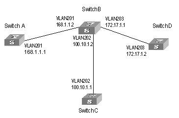
I. Network requirements
Figure 2-1 illustrates a network with four switches, which connects to each other through Ethernet.
The four switches all support MPLS, and LSP can be established between any two switches with the routing protocol OSPF.LDP establishes LSP by using routing information of OSPF.
II. Network diagram
III. Configuration procedure
1) Configure Switch A
# Configure LSR ID and enable MPLS and LDP.
[H3C] mpls lsr-id 168.1.1.1
[H3C] mpls
[H3C-mpls] quit
[H3C] mpls ldp
# Configure IP address and enable MPLS and LDP for VLAN interface 201.
[H3C] vlan 201
[H3C-vlan201] port gigabitethernet 2/1/1
[H3C-vlan201] quit
[H3C] interface Vlan-interface 201
[H3C-Vlan-interface201] ip address 168.1.1.1 255.255.0.0
[H3C-Vlan-interface201] mpls
[H3C-Vlan-interface201] mpls ldp enable
[H3C-Vlan-interface201] mpls ldp transport-ip interface
# Enable OSPF on the interface connecting Switch A with Switch B.
[H3C] Router id 168.1.1.1
[H3C] ospf
[H3C-ospf-1] area 0
[H3C-ospf-1-area-0.0.0.0] network 168.1.0.0 0.0.255.255
2) Configure Switch B
# Configure LSR ID and enable MPLS and LDP.
[H3C] mpls lsr-id 172.17.1.1
[H3C] mpls
[H3C-mpls] quit
[H3C] mpls ldp
# Configure IP address and enable MPLS and LDP for VLAN interface 201.
[H3C] vlan 201
[H3C-vlan201] port gigabitethernet 2/1/1
[H3C-vlan201] quit
[H3C] interface vlan-interface 201
[H3C-Vlan-interface201] ip address 168.1.1.2 255.255.0.0
[H3C-Vlan-interface201] mpls
[H3C-Vlan-interface201] mpls ldp enable
[H3C-Vlan-interface201] mpls ldp transport-ip interface
# Configure IP address and enable MPLS and LDP for VLAN interface 203.
[H3C] vlan 203
[H3C-vlan203] port gigabitethernet 2/1/3
[H3C-vlan203] quit
[H3C] interface vlan-interface 203
[H3C-Vlan-interface203] ip address 172.17.1.1 255.255.0.0
[H3C-Vlan-interface203] mpls
[H3C-Vlan-interface203] mpls ldp enable
[H3C-Vlan-interface203] mpls ldp transport-ip interface
# Configure IP address and enable MPLS and LDP for VLAN interface 202.
[H3C] vlan 202
[H3C-vlan202] port gigabitethernet 2/1/2
[H3C-vlan202] quit
[H3C] interface Vlan-interface 202
[H3C-Vlan-interface202] ip address 100.10.1.2 255.255.255.0
[H3C-Vlan-interface202] mpls
[H3C-Vlan-interface202] mpls ldp enable
[H3C-Vlan-interface202] mpls ldp transport-ip interface
[H3C-Vlan-interface202] quit
# Enable OSPF on the interfaces respectively connecting Switch B with Switch A, Switch D and Switch C.
[H3C] Router id 172.17.1.1
[H3C] ospf
[H3C-ospf-1] area 0
[H3C-ospf-1-area-0.0.0.0] network 168.1.0.0 0.0.255.255
[H3C-ospf-1-area-0.0.0.0] network 172.17.0.0 0.0.255.255
[H3C-ospf-1-area-0.0.0.0] network 100.10.1.0 0.0.0.255
[H3C-ospf-1-area-0.0.0.0] quit
3) Configure Switch C
# Configure LSR ID and enable MPLS and LDP.
[H3C] mpls lsr-id 100.10.1.1
[H3C] mpls
[H3C-mpls] quit
[H3C] mpls ldp
# Configure IP address and enable LDP and MPLS for VLAN interface 202.
[H3C] vlan 202
[H3C-vlan202] port gigabitethernet 2/1/1
[H3C-vlan202] quit
[H3C] interface Vlan-interface 202
[H3C-Vlan-interface202] ip address 100.10.1.1 255.255.255.0
[H3C-Vlan-interface202] mpls
[H3C-Vlan-interface202] mpls ldp enable
[H3C-Vlan-interface202] quit
# Enable OSPF on the interface connecting Switch C with Switch B.
[H3C] Router id 100.10.1.1
[H3C] ospf
[H3C-ospf-1] area 0
[H3C-ospf-1-area-0.0.0.0] network 100.10.1.0 0.0.0.255
4) Configure Switch D
# Configure LSR ID and enable MPLS and LDP.
[H3C] mpls lsr-id 172.17.1.2
[H3C] mpls
[H3C-mpls] quit
[H3C] mpls ldp
# Configure IP address and enable MPLS and LDP for VLAN interface 203.
[H3C] vlan 203
[H3C-vlan203] port gigabitethernet 2/1/3
[H3C-vlan203] quit
[H3C] interface vlan-interface 203
[H3C-Vlan-interface203] ip address 172.17.1.2 255.255.0.0
[H3C-Vlan-interface203] mpls
[H3C-Vlan-interface203] mpls ldp enable
# Enable OSPF on the interface connecting Switch D with Switch B.
[H3C] Router id 172.17.1.2
[H3C] ospf
[H3C-ospf-1] area 0
[H3C-ospf-1-area-0.0.0.0] network 172.17.0.0 0.0.255.255
2.6 Troubleshooting MPLS Configuration
Symptom: Session cannot be setup with the peer after LDP is enabled on the interface.
Troubleshooting:
Cause 1: Loop detection configuration is different at the two ends.
Solution: Check loop detection configuration at both ends to see if one end is configured while the other end is not (this will result in session negotiation failure).
Cause 2: Local machine cannot get the route to peer LSR ID, so TCP connection cannot be set up and session cannot be established.
Solution: The default address for session transfer is MPLS LSR ID. The local machine should issue the LSR ID route (often the Loopback address) and lean the peer LSR ID route.
Chapter 3 BGP/MPLS VPN Configuration
3.1 BGP/MPLS VPN Overview
Traditional VPN, for which layer 2 tunneling protocols (L2TP, L2F and PPTP, and so on.) or layer 3 tunnel technology (IPSec, GRE and so on.) is adopted, is a great success and is therefore widely used. However, along with the increase of the size of VPNs , the deficiency of traditional VPN in such aspects as expansibility and manageability becomes more and more obvious. In addition, QoS (Quality of Service) and security are also the difficult problem for traditional VPN.
Using the MPLS technology, service providers can implement the IP-based VPN services easily and enable their networks to meet the expansibility and manageability requirement for VPN. The VPN constructed by using MPLS also provides the possibility for the implementation of value-added service. Multiple VPNs can be formed from a single access point, and each VPN represents a different service, making the network able to transmit services of different types in a flexible way.
Product currently provides comparatively complete BGP/MPLS VPN networking capabilities:
l Address isolation, allowing the overlap of address of different VPNs and public networks.
l Supporting MBGP advertising VPN routing information through public network, establishing BGP/MPLS VPN.
l Forwarding VPN data stream over MPLS LSP.
l Providing MPLS VPN performance monitoring and fault detecting tools.
3.1.1 BGP/MPLS VPN Model
I. BGP/MPLS VPN model
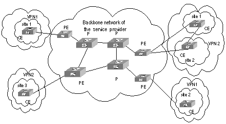
As shown in Figure 3-1, MPLS VPN model contains three parts: CE, PE and P.
l CE (Customer Edge) device: It is a composing part of the customer network, which is usually connected with the service provider directly through an interface. It may be a router or a switch which cannot sense the existence of VPN.
l PE (Provider Edge) router: It is the Provider Edge router, namely the edge device of the provider network, which connects with your CE directly. In MPLS network, PE router processes all the operations for VPN.PE needs to possess MPLS basic forwarding capability.
l P (Provider) router: It is the backbone router in the provider network, which is not connected with CE directly. P router needs to possess MPLS basic forwarding capability.
The classification of CE and PE mainly depends on the range for the management of the provider and the customer, and CE and PE are the edges of the management ranges.
II. Nested BGP/MPLS VPN model
In a basic BGP/MPLS VPN model, the PEs are in the network of the service provider and are managed by the service provider.
When a VPN user wants to subdivide the VPN into multiple VPNs, the traditional solution is to configure these VPNs directly on the PEs of the service provider. This solution is easy to implement, but has the following disadvantages: the number of the VPNs carried on PEs may increase rapidly; the operator may have to perform more operations when required by a user to adjust the relation between the user's internal VPNs. These disadvantages not only increase the network operating cost, but also bring relevant management and security issues.
The nested VPN is a better solution. Its main idea is to transfer VPNv4 route between PE and CE of common BGP MPLS/VPN such that user themselves can manage their internal VPN division, and the service provider can be saved from participating into users' internal VPN management.
The following figure shows the network model for nested VPN:
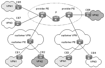
Figure 3-2 Network model for nested BGP/MPLS VPN
III. Basic concepts in BGP/MPLS VPN
1) VPN-instance
VPN-instance is an important concept in VPN routing in MPLS. In an MPLS VPN implementation, each site corresponds to a specific VPN-instance on PE (their association is implemented by binding VPN-instance to the VALN interface). If subscribers on one site belong to multiple VPNs, then the corresponding VPN-instance includes information about all these VPNs.
Specifically, such information should be included in VPN-instance: label forwarding table, IP routing table, the interfaces bound with VPN-instance, and the management information (RD, route filtering policy, member interface list, and so on). It includes the VPN membership and routing rules of this site.
PE is responsible for updating and maintaining the relationship between VPN-instance and VPN. To avoid data leakage from the VPN and illegal data entering into the VPN, each VPN-instance on the PE has an independent set of routing table and label forwarding table, in which the forwarding information of the message is saved
2) MBGP
MBGP (multiprotocol extensions for BGP-4, see RFC2283) propagates VPN membership information and routes between PE routers. It features backward compatibility: It not only supports traditional IPv4 address family, but also supports other address families, for example, VPN-IPv4 address family. MP-BGP ensures that VPN private routes are only advertised within VPNs, as well as implementing communication between MPLS VPN members.
3) VPN-IPv4 address
VPN is just a private network, so it can use the same IP address to indicate different sites. But the IP address is supposed as unique when MP-BGP advertises CE routes between PE routers, so routing errors may occur for the different meaning in two systems. The solution is to switch IPv4 addresses to VPN-IPv4 address to generate globally unique addresses before advertising them, so PE routers is required to support MP-BGP.
A VPN-IPv4 address consists of 12 bytes, and the first eight bytes represent the RD (Route Distinguisher), which are followed by a 4-byte IPv4 address. The service providers can distribute RD independently. However, their special AS (Autonomous System) number must be taken as a part of the RD. After being processed in this way, even if the 4-byte IPv4 address contained in VPN-IPv4 address has been overlapped, the VPN-IPv4 address can still maintain globally unique. RD is only used within the carrier network to differentiate routes. When the RD is 0, a VPN-IPv4 address is just a IPv4 address in general sense.
The route received by PE from CE is the IPv4 route that needs to be redistributed into VPN-instance routing table, and in this case a RD needs to be added. It is recommended that the same RD be configured for all routes from the same user site.
IV. VPN Target attribute
VPN Target attribute is one of the MBGP extension community attributes and is used to limit VPN routing information advertisement. It identifies the set of sites that can use some route, namely by which Sites this route can be received, and the PE router can receive the route transmitted by which Sites. The PE routers connected with the site specified in VPN Target can all receive the routes with this attribute.
For PE routers, there are two sets of VPN Target attributes: one of them, referred to as Export Targets, is added to the route received from a direct-connect site in advertising local routes to remote PE routers. And the other one, known as Import Targets, is used to decide which routes can be imported into the routing table of this site in receiving routes from remote PE routers.
When matching the VPN Target attribute carried by the route to filter the routing information received by the PE router, if the export VPN target set of the received route contains identical items with the import VPN target set of the local end, the route is imported into the VPN routing table and then advertised to the connected CE . Otherwise, the route will be rejected.
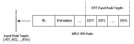
Figure 3-3 Route filtering through matching VPN Target attribute
& Note:
The routes for other VPNs will not appear in the VPN's routing table by using VPN Target attribute to filter routing information received at PE router, so the CE-transmitted data will only be forwarded within the VPN.
3.1.2 BGP/MPLS VPN Implementation
BGP/MPLS VPN works on this principle: It uses BGP to propagate VPN private routing information on carrier backbone network, and uses MPLS to forward VPN service traffic.
The following are introductions to BGP/MPLS implementation from two aspects: advertising VPN routing information and forwarding VPN packets.
I. Advertising VPN routing information
Routing information exchange has the following four types:
1) Between CE and PE
A PE router can learn routing information about the CE connected to it through static route, RIP (supporting multi-instance), OSPF (supporting multi-instance) or EBGP, and imports it in a vpn-instance.
2) Between ingress PE and egress PE
The ingress PE router uses MP-BGP to send information across public network: It advertises routing information learned from CE to the egress PE router (with MPLS label) and learns the CE routing information learned at the egress PE router.
The internal connectivity among the VPN internal nodes is ensured through enabling IGP (for example, RIP and OSPF) or configuring static routes on the PEs.
3) LSP setup between PEs
LSPs must be set up between PEs for VPN data traffic forwarding with MPLS LSP. The PE router which receives packets from CE and create label protocol stack is called Ingress LSR, while the BGP next hop (Egress PE router) is Egress LSR. Using LDP to create fully connected LSPs among PEs.
4) Between PE and CE
A CE can learn remote VPN routes from the PE connected through static routes, RIP, OSPF or EBGP.
With above-mentioned steps, reachable routes can be established between CEs, for transmission of VPN private routing information over public network.
II. Forwarding VPN packets
On the ingress PE, two-layer label stack is formed for each VPN packet:
Interior-layer label, also called MPLS label, is at the bottom of the label stack and distributed by M-BGP when the egress PE advertises routing information (in VPN forwarding table) to ingress GE. When VPN packets from public network reach the CE, they can be forwarded from the designated interface to the designated CE or site by searching for the target MPLS forwarding table according to the labels contained.
Exterior-layer label, known as LSP initialization label, distributed by MPLS LDP, is at the top of the label stack and indicates an LSP from the ingress PE to egress PE. By the switching of exterior-layer label, VPN packets can be forwarded along the LSP to the peer PE.
Figure 3-4 illustrates the details:
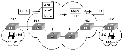
Figure 3-4 Forwarding VPN packets
1) Site 1 sends an IPv4 packet with the destination address 1.1.1.2 to CE1. CE1 looks up the IP routing table for a matched entry and sends the packet to PE1 according to the matched entry.
2) Depending on the interface the packet reaches and the destination of it, PE1 looks up the VPN-instance entry to obtain interior-layer label, exterior-layer label, BGP next hop (PE2), and output interfaces. After the establishment of labels, PE1 forwards MPLS packets to the first P of LSP through output interface.
3) Each P router on LSP forwards MPLS packets using exterior-layer label to the penultimate-hop router, namely the P router before PE2. The penultimate-hop router extracts the exterior-layer and sends MPLS packet to PE2.
4) PE2 looks up in the MPLS forwarding table according to the interior-layer label and destination address to determine the egress interface for labeling operation and the packet. It then extracts the interior-layer label and forwards through the egress interface the IPv4 packet to CE2.
5) CE2 looks up in the routing table and sends the packet in normal IPv4 packet forwarding mode to the site2.
3.1.3 Nested BGP/MPLS VPN Implementation
When implementing a nested BGP/MPLS VPN, pay attention to the following items:
l No address overlap is allowed between user's internal sub-VPNs.
l To ensure the VPN routing information is correctly advertised over the backbone network, the VPN-Targets of the user VPN and the internal sub-VPNs cannot be overlapped and must be specified by the service provider.
l The provider PE and the customer PE must be directly connected and cannot exchange VPNv4 route in Multihop-EBGP mode.
Before configuring a nested BGP/MPLS VPN, you must complete the following tasks:
l Configuring IGP on the MPLS backbone network (including provider PE and P routers) to implement the IP connectivity on the backbone network.
l Configuring basic MPLS capability on the MPLS backbone network.
l Configuring MPLS LDP and setting up LDP LSP on the MPLS backbone network.
l Configuring BGP on the MPLS backbone network (create IBGP peers between provider PEs).
l Configuring basic MPLS capability on user-end network (including customer PEs).
3.1.4 Hierarchical BGP/MPLS VPN Implementation
As PE is required to aggregate multiple VPN routes on a BGP/MPLS VPN, it is prone to forming a bottleneck in a large-scale deployment or in the case that PE capacity is small. To solve the problem, H3C Technologies introduced the HoVPN (Hierarchy of VPN, Hierarchical BGP/MPLS VPN) solution.
Hierarchical BGP/MPLS VPN divides an MPLS VPN into several MPLS VPNs in a hierarchical network structure. Each VPN takes on a role depending on its level. There are high performance requirements in routing and forwarding on the PEs at the higher level of MPLS VPN, because they are primarily used for connecting the backbone networks and providing access service for huge VPN clients. However, such requirements are relatively low for PEs at the lower level of the network as they primarily function to access the VPN clients at the edges. Congruous with the IP network model, HoVPN model improves the scalability of BGP/MPLS VPN, and hence allows lower-layer MPLS VPNs comprising low-end equipment to provide MPLS VPN accessing and interconnect through the high-end MPLS VPN backbone.
As shown in Figure 3-5, the PEs directly connected with user devices are called UPE (underlayer PE or user-end PE); the devices in the core network connected with the UPEs are called SPE (superstratum PE or service-provider-end PE).
Hierarchical PEs have the same appearance as that of the traditional PEs and can coexist with other PEs in the same MPLS network.
UPEs are responsible for user access; they only maintain the routes of directly connected VPN sites, but not that of the remote sites. SPEs, however, are responsible for the maintenance and advertisement of VPN routes; they maintain all the routes of the VPNs connected by their UPEs, including the routes in both local and remote sites.
UPE and SPE are relative concepts. In a multi-layer PE architecture, an upper layer PE is an SPE for its lower layer PE, and a lower layer PE is an UPE for its upper layer PE.
The MBGP runs between SPE and UPE can be either MP-IBGP or MP-EBGP, depending on whether the SPE and the UPE are in the same AS.
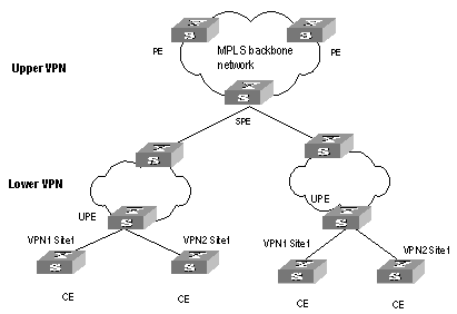
Figure 3-5 Hierarchical BGP/MPLS VPN
3.1.5 Introduction to OSPF Multi-instance
As one of the most popular IGP routing protocols, OSPF is used as an internal routing protocol in many VPNs. Using OSPF on PE-CE links brings convenience to you because in this case CE routers only need to support OSPF protocol, without the need of supporting other protocols, and network administrator only have to know the OSPF protocol. If you want to transform conventional OSPF backbone into BGP/MPLS VPN, using OSPF between PE and CE can simplify this transform process.
Therefore IETF raised two new OSPF VPN extension drafts, to provide a complete solution to SPPF problems in BGP/MPLS VPN application when OSPF is used as PE-CE routing protocol. In this case, PE router must be able to run multiple OSPF instances, each of which corresponds to one VPN instance, owns an individual interface, routing table, and sends VPN routing information over MPLS network using BGP/OSPF interaction.
If supporting OSPF multi-instance, one router can run multiple OSPF processes, which can be bound to different VPN instances. In practice, you can create one OSPF instance for each service type. OSPF multi-instance can fully isolate different services in transmission, which can solve security problems with low cost to meet the needs of customers. Generally, OSPF multi-instance is run on PEs; The CE running OSPF multi-instance in the LAN is called multi-VPN-instance CE. At present, isolation of LAN services implements by VLAN function of the switch. OSPF Multi-VPN-Instance CE provides schemes of services isolation implemented on routers.
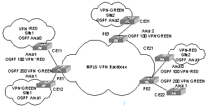
Figure 3-6 OSPF multi-instance application in MPLS/BGP VPN PE
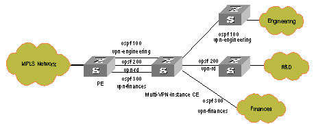
Figure 3-7 Multi-VPN-instance CE application in conventional LAN
3.1.6 Introduction to Multi-Role Host
The VPN attribute of the packets from a CE to its PE lies on the VPN bound with the ingress interface. This, in fact determines that all the CEs forwarded by the PE through the same ingress interface belong to the same VPN; but in actual network environments, a CE may need to access multiple VPNs through one physical interface. Though you can configure different logical interfaces to meet this need, this compromised method brings additional configuration burden and has limitation in actual use.
To resolve this problem, the idea of multi-role host is generated. Specifically to say, this idea is to differentiate the accesses to different VPNs through configuring policy routing based on IP addresses, and transmit downstream data flow from PE to CE by configuring static routing. The static routing under multi-role host circumstance is different from common hosts; it is implemented by specifying an interface of another VPN as the egress interface through a static route in a VPN; and thus allowing one logical interface to access multiple VPNs.
3.2 BGP/MPLS VPN Configuration
3.2.1 Configuring Various Kinds of Routers
Implementing BGP/MPLS VPN functions requires the following procedures in general: Configure basic information on PE, CE and P; establish the logical or physical link with IP capabilities from PE to PE; advertise and update VPN network information.
I. CE router
The configuration on CE is relative simple. Only static route, RIP, OSPF or EBGP configuration is needed for VPN routing information exchange with the PE connected, MPLS configuration is not needed.
II. PE router
The configuration on PE is relative complex. After the configuration, the PE implements MPLS/BGP VPN core functions.
The following sections describe the configuration tasks on a PE device:
l Configuring basic MPLS capabilities and the joint maintenance of LSP with a P device and other PE devices
l Configuring BGP/MPLS VPN Site, namely, VPN-instance
l Configuring static route, RIP, OSPF, or EBGP for VPN routing information exchange with CE
l Configuring IGP for intra-PE interconnection
l Configuring MBGP for VPN routing information exchange between PEs
III. P router
The configuration on P device is relative simple. The main task is to configure MPLS basic capacity on the P device to support LDP and MPLS forwarding.
The following are detailed configurations.
3.2.2 Configuring CE Router
As a customer-side device, only basic configuration is required on a CE router, for routing information exchange with PE router. Currently route switching modes available include static route, RIP, OSPF, EBGP, and so on.
I. Creating static route
If you select static route mode for CE-PE route switching, you should then configure a private static route pointing to PE on CE.
Perform the following configuration in the system view.
Table 3-1 Create/delete a static route in VPN instance routing table
|
Operation |
Command |
|
Create a specified VPN-instance static route |
ip route-static ip-address { mask | mask-length } { interface-name | gateway-address } [ preference preference-value ] [ reject | blackhole ] |
|
Delete a specified VPN-instance static route |
undo ip route-static ip-address { mask | mask-length } [ interface-name | gateway-address ] [ preference preference-value ] |
By default, the preference value for a static route is 60. You can also specify preference for a static route.
II. Configuring RIP
If you select RIP mode for CE-PE route switching, you should then configure RIP on CE. For detailed RIP configuration steps, see the RIP configuration part in routing protocol in H3C S9500 Series Routing Switches Operation Manual.
III. Configuring OSPF
If you select OSPF mode for CE-PE route switching, you should then configure OSPF on CE. For configuring OSPF, see the routing protocol part in H3C S9500 Series Routing Switches Operation Manual.
You must configure OSPF multi-instance to isolate services of different VPNs on CE router, which is now called Multi-VPN-Instance CE.
You can bind OSPF processes with VPN with the following command in OSPF view.
Table 3-2 Configure the router as multi-VPN-instance CE
|
Operation |
Command |
|
Configure the router as multi-VPN-instance CE |
vpn-instance-capability simple |
|
Remove the configuration |
undo vpn-instance-capability |
IV. Configuring EBGP
If you select BGP mode for CE-PE route switching, you should then configure EBGP peer, import direct-connect route, static route and other IGP routes, for BGP to advertise VPN routes to PE.
3.2.3 Configuring PE Router
I. Configuring basic MPLS capability
It includes configuring MPLS LSR ID, enable MPLS globally and enable MPLS in the corresponding VLAN interface view.
Refer to Chapter 2 MPLS Basic Capability Configuration for details.
II. Defining BGP/MPLS VPN site
1) Create VPN-instance and enter VPN-instance view
The VPN instance is associated with a site. The VPN membership and routing rules of a site is configured in the corresponding VPN instance.
This command is used to create a new VPN-instance and enter the VPN-instance view, or directly enter the VPN-instance view if the VPN-instance already exists.
Perform the following configuration in the system view.
Table 3-3 Create a VPN-instance and enter VPN-instance view
|
Operation |
Command |
|
Create a VPN-instance and enter VPN-instance view |
ip vpn-instance vpn-instance-name |
|
Delete a VPN-instance |
undo ip vpn-instance vpn-instance-name |
By default, no VPN-instance is defined.
2) Configure RD for the vpn-instance
After PE router is configured with RD, when a VPN route learned from CE is imported into BGP, BGP attaches the RD in front of the IPv4 address. Then the general IPv4 address which may overlaps between several VPN IPv4 addresses in the VPN is turned into a globally unique VPN IPv4 address and thus ensure the correct routing in the VPN.
Perform the following configuration in VPN-instance view.
Table 3-4 Configure RD for the VPN-instance
|
Operation |
Command |
|
Configure RD for the VPN-instance |
route-distinguisher route-distinguisher |
The parameter in the above command has no default value. A VPN-instance works only when a RD is configured for it. Other parameters for a VPN-instance cannot be configured before configuring a RD for it.
To modify the RD, you must first delete the VPN-instance and reconfigure it.
3) Configure VPN-instance description
Perform the following configuration in VPN-instance view
Table 3-5 Configure VPN-instance description
|
Operation |
Command |
|
Configure VPN-instance description |
description vpn-instance-description |
|
Delete VPN-instance description |
undo description |
4) Configure VPN-target attribute for the VPN-instance
VPN-target attribute, a BGP extension community attribute, controls advertisement of VPN routing information.
The following is the advertisement controlling process of VPN routing information:
l When BGP is imported into a VPN route learned at CE, it associates a VPN-target extension community attribute list for the route. Usually the list is the VPN-instance output routing attribute list which is associated with CE.
l VPN instance defines input routing attribute list according to the import-extcommunity in VPN-target, defines the acceptable route range and import it.
l VPN instance modifies VPN-target attributes for the routes to be advertised, according to the export-extcommunity in VPN-target.
Like an RD, an extension community includes an ASN plus an arbitrary number or an IP address plus an arbitrary number. There are two types of formats:
The first one is related to autonomous system number (ASN), in the form of 16-bit ASN (can be 0 here): 32-bit user-defined number, for example, 100:1.
The second one is related to IP address, in the form of 32-bit IP address (can be 0.0.0.0 here):16-bit user-defined number, for example, 172.1.1.1:1.
Perform the following configuration in the VPN-instance view.
Table 3-6 Create VPN-target extended community for the VPN-instance
|
Operation |
Command |
|
Configure VPN-target extended community for the VPN-instance |
vpn-target vpn-target-extcommunity [ import-extcommunity | export-extcommunity | both ] |
|
Delete the specified VPN-target attribute from the VPN-target attribute list associated with the VPN-instance |
undo vpn-target vpn-target-extcommunity [ import-extcommunity | export-extcommunity | both ] |
By default, the value is both. In general all Sites in a VPN can be interconnected, and the import-extcommunity and export-extcommunity attributes are the same, so you can execute the command only with the both option.
Up to 16 VPN-targets can be configured with a command, and up to 20 vpn-targets can be configured for a VPN-instance.
5) Limit the maximum number of routes in a VPN-instance
This command is used to limit the maximum number of routes for a VPN-instance so as to avoid too many routes imported from a Site.
Perform the following configuration in the VPN-instance view.
Table 3-7 Limit the maximum number of routes in the VPN-instance
|
Operation |
Command |
|
Limit the maximum number of routes in the VPN-instance |
routing-table limit integer { alarm-integer | syslog-alert } |
|
Remove the maximum number limitation |
undo routing-table limit |
Integer is in the range of 1 to 65536 and alarm-integer is in the range of 1 to 100.
& Note:
Changing the maximum route limit for VPN-instance will not affect the existing routing table. To make the new configuration take effect immediately, you should rebuild the corresponding routing protocol or perform shutdown/undo shutdown operation on the corresponding interface.
6) Configure vlan-id larger than 1024 on the fast Ethernet port of Trunk type (Optional)
Configure vlan-id larger than 1024, with the range of MPLS/VPN VLANs allowed to pass the port from vlan-id to vlan-id + 1023
Perform the following configuration in Ethernet port view.
Table 3-8 Configure the vlan id range of MPLS/VPN VLANs allowed to pass the Ethernet port of C card
|
Operation |
Command |
|
Configure the vlan id range of MPLS/VPN VLANs allowed to pass the Trunk fast Ethernet port |
port trunk mpls vlan from vlan-id [ to ] vlanid |
|
Remove the configured vlan id range of MPLS/VPN VLANs allowed to pass the Trunk fast Ethernet port |
undo port trunk mpls |
By default, the vlan-id range of MPLS/VPN VLANs is from 0 to 1023, and the default value of vlan-id is 0. The value range of vlan-id is from 1 to 3071.
![]() Caution:
Caution:
l This command is only applicable to fast Ethernet ports of C cards.
l This command can only be executed on Trunk ports, and MPLS/VPN enabled VLANs and VLANs out of the configured range are excluded (a Trunk port contains VLAN1 by default, so it is not judged).
7) Associate interface with VPN-instance
VPN instance is associated with the direct-connect Site through interface binding. When the packets from the Site reach the PE router though the interface bound, then the PE can look routing information (including next hop, label, egress interface, and so on.) up in the corresponding VPN-instance.
This command can associate a VPN-instance with an interface.
Perform the following configuration in VLAN interface view.
Table 3-9 Associate interface with VPN-instance
|
Operation |
Command |
|
Associate interface with VPN-instance |
ip binding vpn-instance vpn-instance-name |
|
Remove the association of the interface with VPN-instance |
undo ip binding vpn-instance vpn-instance-name |
![]() Caution:
Caution:
As executing the ip binding vpn-instance command on an interface will delete the IP address of the interface, you must configure the IP address of the interface after executing that command when you bind the interface with a VPN-instance.
III. Configuring PE-CE route exchanging
These route exchanging modes are available between PE and CE: static route, RIP, OSPF, EBGP.
1) Configure static route on PE
You can configure a static route pointing to CE on PE for it to learn VPN routing information from CE.
Perform the following configuration in the system view.
Table 3-10 Create/Delete static route in VPN-instance routing table
|
Operation |
Command |
|
Create the static route of a specific VPN-instance |
ip route-static vpn-instance vpn-instance-name1 vpn-instance-name2 … ip-address { mask | mask-length } { interface-name | [ vpn-instance vpn-nexthop-name vpn-nexthop-address ] } [ preference preference-value | public ] [ reject | blackhole ] |
|
Delete a static route of a specific VPN-instance |
undo ip route-static vpn-instance vpn-instance-name1 vpn-instance-name2 … ip-address { mask | mask-length } { interface-name [ vpn-instance vpn-nexthop-name vpn-nexthop-address ] } [ preference preference-value | public ] [ reject | blackhole ] |
By default, the preference value for a static route is 60. You can also specify another preference for the static route you are configuring.
2) Configure RIP multi-instance
If you select RIP mode for CE-PE route switching, you should then specify running environment for RIP instance on PE. With this command, you can enter RIP view and import and advertise RIP instance in the view.
Perform the following configuration in the RIP view.
Table 3-11 Configure PE-CE RIP instance
|
Operation |
Command |
|
Create PE-CE RIP instance |
ipv4-family [ unicast ] vpn-instance vpn-instance-name |
|
Delete PE-CE RIP instance |
Then configuring RIP multi-instance to import IBGP route.
For details about RIP configuration, see RIP configuration section in Routing Protocol of this manual.
3) Configure OSPF multi-instance on PE
If you select OSPF mode for CE-PE route switching, you should then configure OSPF multi-instance on PE. Other configurations, such as MPLS basic configuration, VPN-instance configuration, do not change. Noted that when OSPF routes and direct-connect routes are imported in the VPN instance address family view, BGP routes should also be imported into OSPF. Here only introduces OSPF multi-instance configuration in detail.
First step: Configure OSPF process.
Perform the following configuration in the system view.
Table 3-12 Configure OSPF process
|
Operation |
Command |
|
Configure an OSPF process |
ospf process-id [ router-id router-id-number ] [ vpn-instance vpn-instance-name ] |
|
Delete an OSPF process |
undo ospf process-id |
By default, the process index is 1.
![]() Caution:
Caution:
An OSPF process can only belong to one VPN instance, while one VPN instance may contain multiple OSPF processes. By default, an OSPF process belongs to public network.
Step 2: Configure Domain ID
The Domain ID is used to identify an OSPF autonomous system (AS), and the same OSPF domain must have the same Domain ID. One process can be configured with only one Domain ID; different processes can be configured with the same Domain ID or different Domain IDs.
Perform the following configuration in the OSPF view.
Table 3-13 Configure Domain ID
|
Operation |
Command |
|
Configure Domain ID |
domain-id { id-number | id-addr } |
|
Return to the default value |
undo domain-id |
By default, id-number is 0 and id-addr is 0.0.0.0.
It is recommended that all OSPF instances in a VPN are configured with either the same domain ID or the default value.
![]() Caution:
Caution:
The configured value will not take effect unit the command reset ospf is executed.
Step 3: Configure tag for imported VPN route (optional)
If a VPN Site links to multiple PEs, routing ring may present when the routes learned by MPLS/BGP are received by another PE router in being advertised by category-5/-7 LSA of a PE to the VPN Site. To solve this problem, you should configure Route-tag. It is recommended to configure identical Route-tag for the PEs in the same VPN.
Perform the following configuration in the OSPF view.
![]() Caution:
Caution:
The configured Route-tag will not take effect unit the command reset ospf is executed.
Table 3-14 Configure tag for imported VPN route
|
Operation |
Command |
|
Configure tag for imported VPN route |
route-tag tag-number |
|
Return to the default value |
undo route-tag |
tag-number is used to identify Tag value; by default, the first two bytes are fixed, that is, 0xD000, and the last two bytes is AS number of local BGP. For example, the AS number of local BGP is 100, and then its default tag value is 3489661028 in decimal notation. This value is an integer ranging from 0 to 4294967295.
Step 4: Configure Sham-link (optional)
Sham-links are required between two PEs when Backdoor links (that is, the OSPF links that do not pass through the MPLS backbone network) exist between the two PEs and data is expected to be transported over the MPLS backbone. A Sham-link between two PEs is considered as a link in OSPF domain. Its source and destination addresses are both the Loopback interface address with 32-bit mask, but this Loopback interface should be bound to a VPN instance and direct routes must be imported into BGP by BGP. OSPF processes of the VPN cannot directly import the routes of the Loopback interface (so the import direct command cannot be executed in an OSPF processes of VPN); instead, an OSPF process can only advertise the route indirectly by importing a BGP route.
Perform the following configuration in the OSPF area view.
Table 3-15 Configure Sham-link
|
Operation |
Command |
|
Configure Sham-link |
sham-link source-addr destination-addr [ cost cost-value ] [ simple password | md5 keyid key ] [ dead seconds ] [ hello seconds ] [ retransimit seconds ] [ trans-delay seconds ] |
|
Delete a Sham-link |
undo sham-link source-addr destination-addr |
By default, the cost value is 1, dead value is 40 seconds, hello value is 10 seconds, retransmit value is 5 seconds and trans-delay value is 1 second.
4) Configure EBGP on PE
If you select EBGP between PE and CE, you should configure a neighbor for each VPN in VPN instance address family sub-view, and import IGP route of CE.
Step 1: Configure peer group
Configuring peer group in VPN instance address family view.
Table 3-16 Configure peer group
|
Operation |
Command |
|
Configure a peer group |
group group-name [ internal | external ] |
|
Delete the specified peer group |
undo group group-name |
By default, the peer group is configured as internal. When BGP mode is used for PE-CE route switching, they often belong to different ASs, so you should configure EBGP peer as external.
Step 2: Configure AS number for a specific neighbor and add group member to a peer group
When EBGP mode is used for PE-CE route switching, you should configure AS number for a specific neighbor for every CE VPN-instance.
Perform the following configuration in VPN instance address family view.
Table 3-17 Configure AS number for a specific neighbor
|
Operation |
Command |
|
Configure AS number for a specific neighbor |
peer { group-name | [ peer-address group group-name ] } as-number as-number |
|
Delete the AS number of a specific neighbor |
undo peer { group-name | [peer-address group group-name ] } as-number as-number] |
Step 3: Activate peer (group)
By default, BGP neighbor is active while MBGP neighbor is inactive. You should activate MBGP neighbor in VPNv4 sub-address family view.
Perform the following configuration in VPNv4 sub-address family view.
Table 3-18 Activate/deactivate peer (group)
|
Operation |
Command |
|
Activate the peer (group) |
peer group-name enable |
|
Deactivate the peer (group) |
undo peer group-name enable |
Step 4: Configure MBGP to import VPN route of direct-connect CE
To advertise correct VPN route over public network to other PEs with which BGP adjacency has been created, a PE must import the VPN routing information of the direct-connect CE into its MBGP routing table.
For example, if a static route is used between PE and CE, PE must import a static route in VPN-instance address family sub-view of MBGP (import-route static). If RIP is run between PE and CE, PE must import an RIP route in VPN-instance view of MBGP (import-route rip). If BGP is run between PE and CE, MBGP imports a direct-connect route.
Perform the following configuration in VPN instance address family sub-view.
|
Operation |
Command |
|
Import IGP route |
import-route protocol [ process-id ] [ med med ] |
|
Remove IGP route import |
undo import-route protocol |
Step 5: Configure BGP as asynchronous.
Perform the following configuration in VPN instance address family sub-view.
Table 3-20 Configure BGP asynchronous with IGP
|
Operation |
Command |
|
Configure BGP asynchronous with IGP |
undo synchronization |
By default, BGP is in asynchronous mode.
Step 6: Permit route loop configuration in Hub&Spoke networking (optional)
Generally speaking, PE-CE configuration is completed after you specify the AS number of neighbor; for the rest configuration, you can keep the system default values.
In the case of standard BGP, BGP tests routing loop via AS number to avoid generating routing loop. In the case of Hub&Spoke networking, however, PE carries the AS number of the local autonomous system when advertising the routing information to CE, if EBGP is run between PE and CE. Accordingly, the updated routing information will carry the AS number of the local autonomous system when route update is received from CE. In this case, PE will not accept the route update information.
This phenomenon can be avoided by executing the peer allow-as-loop command, which makes the PE still receives the route update information containing the local AS number from CE.
Perform the following configuration in IPv4 instance sub-address family view.
Table 3-21 Configure to allow/disable routing loop
|
Operation |
Command |
|
Configure to allow routing loop |
peer { group-name | peer-address } allow-as-loop asn-limit |
|
Configure to disable routing loop |
undo peer { group-name | peer-address } allow-as-loop asn-limit |
By default, the received route update information is not allowed to generate loop information.
Step 7: Configure BGP features.
IV. Configuring PE-PE route exchanging
To exchange VPN-IPv4 routing information between PEs, you should configure MP-IBGP on PEs.
Perform the following configuration in BGP view or PVN instance address family sub-view.
1) Configure IBGP
These steps are often required.
Step 1: Configure BGP as asynchronous.
Step 2: Configure BGP neighbor.
Note that BGP adjacency is established through Loopback interface and the sub-net mask must be 32 bits.
Step 3: Permit BGP session over any operable TCP interface.
In general, BGP uses the best local address in TCP connection. To keep TCP connection available even when the interface involved fails, you can perform the following configuration to permit BGP session over any interface through which TCP connection with the peer can be set up. The command here is usually executed together with the Loopback interface.
Perform the following configuration in VPNv4 sub-address family view.
Table 3-22 Permit BGP session over any operable TCP interface
|
Operation |
Command |
|
Permit BGP session over any operable TCP interface |
peer { peer-address | group-name } connect-interface { interface-type interface-number } |
|
Use the best local address for TCP connection |
undo peer { peer-address | group-name } connect-interface |
BGP creates BGP adjacency to the peer end using specific interfaces, which is usually the loopback interface. Because this interface is always in the up state, thus it reduces the strike brought by network shock.
2) Configure MP-IBGP
Step 1: Enter protocol address family view.
Perform the following configuration in BGP view.
Table 3-23 Configure VPNv4 address family
|
Operation |
Command |
|
Enter VPNv4 sub-address family view |
ipv4-family vpnv4 [ unicast ] |
|
Delete VPNv4 sub-address family view configuration |
undo ipv4-family vpnv4 [ unicast ] |
Step 2: Configure MBGP neighbor
Configure internal neighbor of MBGP in VPNv4 sub-address family view.
Table 3-24 Configure peer group
|
Operation |
Command |
|
Create a peer group |
group group-name [ internal | external ] |
|
Delete a specific peer group |
undo group group-name |
Choose the internal keyword when using the command to create an IBGP peer group.
Step 3: Activate peer (group)
By default, BGP neighbor is active while MBGP neighbor is inactive. You must enable MBGP neighbor in VPNv4 sub-address family view.
Table 3-25 Enable/disable IBGP peer group
|
Operation |
Command |
|
Enable a peer group |
peer group-name enable |
|
Disable a specific peer group |
undo peer group-name enable |
Step 4: Configure the local address as the next hop in route advertisement (optional)
Since the default value is no configuration, you must show clearly to add in this configuration command when configuring MBGP of PE-PE.
Perform the following configuration in VPNv4 sub-address family view.
Table 3-26 Configure the local address as the next hop in route advertisement
|
Operation |
Command |
|
Configure the local address as the next hop in route advertisement |
peer { peer-address | group-name } next-hop-localpeer { peer-address | group-name } next-hop-local |
|
Remove the configuration |
undo peer { peer-address | group-name } next-hop-local |
Step 5: Transfer BGP update packet without AS number (optional)
Perform the following configuration in VPNv4 sub-address family view.
Table 3-27 Transfer BGP update packet without AS number
|
Operation |
Command |
|
Transfer BGP update packet without AS number |
peer { peer-address | group-name } public-as-only |
|
Transfer BGP update packet with AS number |
undo peer { peer-address | group-name } public-as-only |
Step 6: Advertise default route to the peer (group)
This command adds a default route which uses local address as the next hop on the PE SPE (system processing engine)
Perform the following configuration in VPNv4 sub-address family view.
Table 3-28 Advertise default route to the peer (group)
|
Operation |
Command |
|
Advertise default route to the peer (group) |
peer ip-address default-route-advertise vpn-instance vpn-instance name |
|
Remove to advertise default route to the peer (group) |
undo peer ip-address default-route-advertise vpn-instance vpn-instance name |
Step 7: Configure BGP neighbor as the UPE of BGP/MPLS VPN
This command is only used for UPE (User-end PE) of BGP/MPLS VPN.
Configure the following commands in the VPNv4 sub-address family view.
Table 3-29 Configure BGP neighbor as the UPE of BGP/MPLS VPN
|
Operation |
Command |
|
Configure BGP neighbor as the UPE of BGP/MPLS VPN |
peer peer-address upe |
|
Disable the configuration |
undo peer peer-address upe |
3.2.4 Configuring P Router
P router does not maintain VPN routes, but do keep connection with public network and coordinate with PE in creating LSPs. These configurations are required on P router:
Step 1: Configure MPLS basic capacity and enable LDP on the interfaces connecting P router to PE router, for forwarding MPLS packets. See Chapter 2 MPLS Basic Capability Configuration.
Step 2: Enable OSPF protocol at the interfaces connecting P router to PE router and import direct-connect routes. See “OSPF” part in “Routing Protocol” for details.
3.3 Displaying and Debugging BGP/MPLS VPN
I. Displaying VPN address information from BGP table
After the above configuration, execute display command in any view to display the running of the VPNv4 information in BGP database configuration, and to verify the effect of the configuration.
Table 3-30 Display VPN address information from BGP table
|
Operation |
Command |
|
Display VPN address information from BGP table |
display bgp vpnv4 { all | route-distinguisher rd-value | vpn-instance vpn-instance-name } { group | network | peer | routing-table } |
II. Displaying IP routing table associated with VPN-instance
After the above configuration, you can execute display command in any view to display the corresponding information in the IP routing tables related to VPN-instance, and to verify the effect of the configuration.
Table 3-31 Display IP routing table associated with VPN-instance
|
Operation |
Command |
|
Display IP routing table associated with VPN-instance |
display ip routing-table vpn-instance vpn-instance-name [ [ip-address ] [ verbose ] | statistics ] |
III. Displaying VPN-instance related information
After the above configuration, executing the display command in any view can display the VPN-instance related information, including its RD, description, the interfaces associated with it, and so on. You can view the information to verify the configuration effect.
Table 3-32 Display VPN-instance related information
|
Operation |
Command |
|
Display the VPN-instance related information, including its RD, description, the interfaces associated with it, and so on. |
display ip vpn-instance [ vpn-instance-name | verbose ] |
IV. Debugging information concerning processing BGP
Execute debugging command in user view for the debugging of the related vpn-instance information.
Table 3-33 Enable the debugging for processing BGP
|
Operation |
Command |
|
Enable the debugging for processing BGP |
debugging bgp { all | event | normal | { keepalive | mp-update | open | packet | update | route-refresh | update } [ receive | send |] [ verbose ] } |
|
Disable the debugging |
undo debugging bgp { {all | event | normal | keepalive | mp-update | open | packet | update | route-refresh } [ receive | send | verbose ] } { all | event | normal | update } |
V. Displaying MPLS L3VPN-LSP information
Table 3-34 Display MPLS L3VPN-LSP information
|
Operation |
Command |
|
Display MPLS L3VPN LSP information |
display mpls l3vpn-lsp [ verbose] include text |
|
Display MPLS L3VPN LSP VPN-instance information |
display mpls l3vpn-lsp [ vpn-instance vpn-instance-name ] [ transit | egress | ingress ] [include text | verbose ] |
VI. Displaying Sham-link
|
Operation |
Command |
|
Display Sham-link |
display ospf [ process-id ] sham-link |
3.4 Typical BGP/MPLS VPN Configuration Example
3.4.1 Integrated BGP/MPLS VPN Configuration Example
I. Network requirements
l VPNA includes CE1 and CE3; VPNB includes CE2 and CE4.
l Subscribers in different VPNs cannot access each other. The VPN-target attribute for VPNA is 111:1 and that for VPNB is 222:2.
l The PEs and P are H3C switches supporting MPLS, and CEs are common layer 3 switches.
& Note:
The configuration in this case is focused on:
l Configure EBGP to exchange VPN routing information between CEs and PEs.
l Configure OSPF for inter-PE communication between PEs.
l Configure MP-IBGP to exchange VPN routing information between PEs.
II. Network diagram
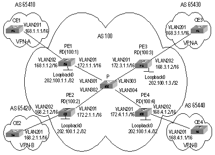
Figure 3-8 Network diagram for integrated BGP/MPLS VPN
III. Configuration procedure
The following are the configuration introduction to PE, CE and P switches.
1) Configure CE1.
# Configure CE1 and PE1 as EBGP neighbors, import direct-connect routes and static routes to import intra-CE1 VPN routes into BGP and advertise to PE1.CE1connects to PE1 through interface Gigabitethernet 2/1/1.
[CE1] vlan 201
[CE1-vlan201] port gigabitethernet 2/1/1
[CE1-vlan201] quit
[CE1] interface Vlan-interface 201
[CE1-Vlan-interface201] ip address 168.1.1.1 255.255.0.0
[CE1-Vlan-interface201] quit
[CE1] bgp 65410
[CE1-bgp] group 168 external
[CE1-bgp] peer 168.1.1.2 group 168 as-number 100
[CE1-bgp] import-route direct
[CE1-bgp] import-route static
& Note:
The configuration on the other three CE switches (CE2 to CE4) is similar to that on CE1, the details are omitted here.
2) Configure PE1
# Configure vpn-instance for VPNA on PE1, as well as other associated attributes to control advertisement of VPN routing information.
[PE1] ip vpn-instance vpna
[PE1-vpn-vpna] route-distinguisher 100:1
[PE1-vpn-vpna] vpn-target 111:1 both
[PE1-vpn-vpna] quit
# Configure PE1 and CE1 as MP-EBGP neighbors, import CE1 VPN routes learned into MBGP VPN-instance address family.
[PE1] bgp 100
[PE1-bgp] ipv4-family vpn-instance vpna
[PE1-bgp-af-vpn-instance] import-route direct
[PE1-bgp-af-vpn-instance] group 168 external
[PE1-bgp-af-vpn-instance] peer 168.1.1.1 group 168 as-number 65410
[PE1-bgp-af- vpn-instance] quit
[PE1-bgp] quit
# Bind the VLAN interface connecting PE1 and CE1 to the VPNA. Note that you should first configure association between the VLAN interface and VPN-instance, and then configure the IP address of the VLAN interface.
[PE1] vlan 202
[PE1-vlan202] port gigabitethernet 2/1/2
[PE1-vlan202] quit
[PE1] interface Vlan-interface 202
[PE1-Vlan-interface202] ip binding vpn-instance vpna
[PE1-Vlan-interface202] ip address 168.1.1.2 255.255.0.0
[PE1-Vlan-interface202] quit
# Configure Loopback interface. (For PE, the IP address for Loopback interface must be a host address with 32-bit mask, to prevent the route is aggregated and then LSP cannot process correctly interior-layer labels.)
[PE1] interface loopback0
[PE1-LoopBack 0] ip address 202.100.1.1 255.255.255.255
[PE1-LoopBack 0] quit
# Configure MPLS basic capacity and enable MPLS and LDP on VLAN interface connecting PE1 and P. Create LSP and achieve MPLS packet forwarding.
[PE1] mpls lsr-id 202.100.1.1
[PE1] mpls
[PE1-mpls] quit
[PE1] mpls ldp
[PE1] vlan 201
[PE1-vlan201] port gigabitethernet 2/1/1
[PE1-vlan201] quit
[PE1] interface Vlan-interface 201
[PE1-Vlan-interface201] ip address 172.1.1.1 255.255.0.0
[PE1-Vlan-interface201] mpls
[PE1-Vlan-interface201] mpls ldp enable
[PE1-Vlan-interface201] quit
# Enable OSPF on the interface connecting PE1 and P and on the Loopback interface, import direct-connect routes. Achieve inter-PE communication.
[PE1] ospf
[PE1-ospf-1] area 0
[PE1-ospf-1-area-0.0.0.0] network 172.1.0.0 0.0.255.255
[PE1-ospf-1-area-0.0.0.0] network 202.100.1.1 0.0.0.0
[PE1-ospf-1-area-0.0.0.0] quit
[PE1-ospf-1] import-route direct
[PE1-ospf-1] quit
# Set up MP-IBGP adjacency between PEs to exchange inter-PE VPN routing information and activate MP-IBGP peer in VPNv4 sub-address family view.
[PE1] bgp 100
[PE1-bgp] group 202 internal
[PE1-bgp] peer 202.100.1.3 group 202
[PE1-bgp] peer 202.100.1.3 connect-interface loopback0
[PE1-bgp] ipv4-family vpnv4
[PE1-bgp-af-vpn] peer 202 enable
[PE1-bgp-af-vpn] peer 202.100.1.3 group 202
[PE1-bgp-af-vpn] quit
[PE1-bgp] quit
3) Configure P:
# Configure MPLS basic capacity, enable LDP on the interfaces connecting P and PE for MPLS packet forwarding.
[P] mpls lsr-id 172.1.1.2
[P] mpls
[P-mpls] quit
[P] mpls ldp
[P] interface loopback0
[P-LoopBack 0] ip address 172.1.1.2 255.255.255.255
[P-LoopBack 0] quit
[P] vlan 301
[P-vlan301] port gigabitethernet 3/1/1
[P-vlan301] quit
[P] interface Vlan-interface 301
[P-Vlan-interface301] ip address 172.1.1.2 255.255.0.0
[P-Vlan-interface301] mpls
[P-Vlan-interface301] mpls ldp enable
[P-Vlan-interface301] quit
[P] vlan 302
[P-vlan302] port gigabitethernet 3/1/2
[P-vlan302] quit
[P] interface Vlan-interface 302
[P-Vlan-interface302] ip address 172.2.1.2 255.255.0.0
[P-Vlan-interface302] mpls
[P-Vlan-interface302] mpls ldp enable
[P-Vlan-interface302] quit
[P] vlan 303
[P-vlan303] port gigabitethernet 3/1/3
[P-vlan303] quit
[P] interface Vlan-interface 303
[P-Vlan-interface303] ip address 172.3.1.2 255.255.0.0
[P-Vlan-interface303] mpls
[P-Vlan-interface303] mpls ldp enable
[P-Vlan-interface303] quit
[P] vlan 304
[P-vlan304] port gigabitethernet 3/1/4
[P-vlan304] quit
[P] interface Vlan-interface 304
[P-Vlan-interface304] ip address 172.4.1.2 255.255.0.0
[P-Vlan-interface304] mpls
[P-Vlan-interface304] mpls ldp enable
[P-Vlan-interface304] quit
# Enable OSPF protocol on the interfaces connecting P and PE, import direct-connect route to achieve inter-PE communication.
[P] ospf
[P-ospf-1] area 0
[P-ospf-1-area-0.0.0.0] network 172.1.1.0 0.0.255.255
[P-ospf-1-area-0.0.0.0] network 172.2.1.0 0.0.255.255
[P-ospf-1-area-0.0.0.0] network 172.3.1.0 0.0.255.255
[P-ospf-1-area-0.0.0.0] network 172.4.1.0 0.0.255.255
[P-ospf-1-area-0.0.0.0] quit
[P-ospf-1] import-route direct
4) Configure PE3
& Note:
The configuration on PE3 is similar to that on PE1, you should pay more attention to VPN routing attribute setting on PE3 to get information about how to control advertisement of a same VPN routing information (with same VPN-target) over MPLS network.
# Create VPN-instance for VPNA on PE3, configure correlative attributes to control advertisement of VPN routing information.
[PE3] ip vpn-instance vpna
[PE3-vpn-vpna] route-distinguisher 100:3
[PE3-vpn-vpna] vpn-target 111:1 both
[PE3-vpn-vpna] quit
# Set up MP-EBGP adjacency between PE3 and CE3, import intra-CE3 VPN routes learned into MBGP VPN-instance address family.
[PE3] bgp 100
[PE3-bgp] ipv4-family vpn-instance vpna
[PE3-bgp-af-vpn-instance] import-route direct
[PE3-bgp-af-vpn-instance] group 168 external
[PE3-bgp-af-vpn-instance] peer 168.3.1.1 group 168 as-number 65430
[PE3-bgp-af-vpn-instance] quit
[PE3-bgp] quit
# Bind the interface connecting PE3 and CE3 to VPNA.
[PE3] vlan 202
[PE3-vlan202] port gigabitethernet 2/1/2
[PE3-vlan202] quit
[PE3] interface Vlan-interface 202
[PE3-Vlan-interface202] ip binding vpn-instance vpna
[PE3-Vlan-interface202] ip address 168.3.1.2 255.255.0.0
[PE3-Vlan-interface202] quit
# Configure Loopback interface
[PE3] interface loopback0
[PE3-LoopBack 0] ip address 202.100.1.3 255.255.255.255
[PE3-LoopBack 0] quit
# Configure MPLS basic capacity and enable MPLS and LDP on VLAN interface connecting PE3 and P. Creates LSP and achieve MPLS packet forwarding.
[PE3] mpls lsr-id 202.100.1.3
[PE3] mpls
[PE3-mpls] quit
[PE3] mpls ldp
[PE3] vlan 201
[PE3-vlan201] interface gigabitethernet 2/1/1
[PE3-vlan201] quit
[PE3] interface Vlan-interface 201
[PE3-Vlan-interface201] ip address 172.3.1.1 255.255.0.0
[PE3-Vlan-interface201] mpls
[PE3-Vlan-interface201] mpls ldp enable
[PE3-Vlan-interface201] quit
# Enable OSPF on the interface connecting PE3 and P and the Loopback interface, import direct-connect routes.
[PE3] ospf
[PE3-ospf-1] area 0
[PE3-ospf-1-area-0.0.0.0] network 172.3.0.0 0.0.255.255
[PE3-ospf-1-area-0.0.0.0] network 202.100.1.3 0.0.0.0
PE3-ospf-1-area-0.0.0.0] quit
[PE3-ospf-1] import-route direct
[PE3-ospf-1-area-0.0.0.0] import-route direct
# Set up MP-IBGP adjacency between PEs to exchange inter-PE VPN routing information.
[PE3] bgp 100
[PE3-bgp] group 202 internal
[PE3-bgp] peer 202.100.1.1 group 202 as-number 100
[PE3-bgp] peer 202.100.1.1 connect-interface loopback0
[PE3-bgp] ipv4-family vpnv4
[PE3-bgp-af-vpn] peer 202 enable
[PE3-bgp-af-vpn] peer 202.100.1.1 group 202
[PE3-bgp-af-vpn] quit
5) Configure PE2 and PE4
The configuration of PE2 and PE4 is similar to that of PE1 and PE3. The details are omitted here.
3.4.2 Extranet Configuration Example
I. Network requirements
Company A and Company B are located at City A and City B respectively. Their headquarters is located at City C. They respectively own VPN1 and VPN2.
In this case, VPN function is provided by MPLS. There are some shared resources at the City C for the two VPNs. All subscribers in both VPNs can access the shared resources, but VPN subscribers in City A and City B cannot access each other.
The two companies cannot use identical IP addresses, for they share the same VPN-instance at PE-C.
& Note:
In the case the configuration is focused on controlling access authority of VPN subscribers at different cities by configuring different VPN-target attributes at different PEs.
II. Network diagram
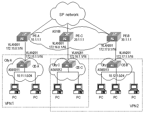
Figure 3-9 Network diagram for Extranet
III. Configuration procedure
& Note:
This configuration procedure has omitted configurations between PE and P, and configurations on CEs. For these details refer to the former example.
1) Configure PE-A:
# Configure VPN-instance 1 for VPN1 on PE-A, so that it can send and receive VPN routing information of VPN-target 111:1.
[PE-A] ip vpn-instance vpn-instance 1
[PE-A-vpn-1] route-distinguisher 100:1
[PE-A-vpn-1] vpn-target 111:1 both
[PE-A-vpn-1] quit
# Set up MP-EBGP adjacency between PE-A and CE-A, import intra-CE-A VPN routes learned into MBGP VPN-instance address family.
[PE-A] bgp 100
[PE-A-bgp] ipv4-family vpn-instance vpn-instance1
[PE-A-bgp-af-vpn-instance] import-route direct
[PE-A-bgp-af-vpn-instance] import-route static
[PE-A-bgp-af-vpn-instance] group 172 external
[PE-A-bgp-af-vpn-instance] peer 172.15.1.1 group 172 as-number 65011
[PE-A-bgp-af-vpn-instance] quit
[PE-A-bgp] quit
# Bind VPN-instance1 with the interface of VLAN301 which connects CE-A.
[PE-A] vlan 301
[PE-A-vlan301] port gigabitethernet 3/1/1
[PE-A-vlan301] quit
[PE-A] interface Vlan-interface 301
[PE-A-Vlan-interface301] ip binding vpn-instance vpn-instance1
[PE-A-Vlan-interface301] ip address 172.15.0.1 255.255.0.0
[PE-A-Vlan-interface301] quit
# Configure Loopback interface
[PE-A] interface loopback 0
[PE-A-LoopBack0] ip address 10.1.1.1 255.255.255.255
[PE-A-LoopBack0] quit
# Configure MPLS basic capacity.
[PE-A] mpls lsr-id 10.1.1.1
[PE-A] mpls
[PE-A-mpls] quit
[PE-A] mpls ldp
# Set up MP-IBGP adjacency between PEs to exchange inter-PE VPN routing information and activate MP-IBGP peer in VPNv4 sub-address family view.
[PE-A] bgp 100
[PE-A-bgp] group 20 internal
[PE-A-bgp] peer 20.1.1.1 group 20
[PE-A-bgp] peer 20.1.1.1 connect-interface loopback 0
[PE-A-bgp] ipv4-family vpnv4
[PE-A-bgp-af-vpn] peer 20 enable
[PE-A-bgp-af-vpn] peer 20.1.1.1 group 20
[PE-A-bgp-af-vpn] quit
2) Configure PE-C.
# Create a VPN-instance 2 on PE-C, so that it can send and receive VPN routing information of VPN-target 111:1 and 222:2.
[PE-C] ip vpn-instance vpn-instance 2
[PE-C-vpn-2] route-distinguisher 100:2
[PE-C-vpn-2] vpn-target 111:1 both
[PE-C-vpn-2] vpn-target 222:2 both
[PE-C-vpn-2] quit
# Set up MP-EBGP adjacency between PE-C and CE-C, import intra-CE-C VPN routes learned into MBGP VPN-instance address family.
[PE-C] bgp 100
[PE-C-bgp] ipv4-family vpn-instance vpn-instance2
[PE-C-bgp-af-vpn-instance] import-route direct
[PE-C-bgp-af-vpn-instance] import-route static
[PE-C-bgp-af-vpn-instance] group 172 external
[PE-C-bgp-af-vpn-instance] peer 172.16.1.1 group 172 as-number 65012
[PE-C-bgp-af-vpn-instance] quit
[PE-C-bgp] quit
# Bind VPN-instance2 with the interface of VLAN301 which connects CE-C.
[PE-C] vlan 301
[PE-C-vlan301] port gigabitethernet 3/1/1
[PE-C-vlan301] quit
[PE-C] interface Vlan-interface 301
[PE-C-Vlan-interface301] ip binding vpn-instance vpn-instance2
[PE-C-Vlan-interface301] ip address 172.16.0.1 255.255.0.0
[PE-C-Vlan-interface301] quit
# Configure Loopback interface
[PE-C] interface loopback 0
[PE-C-LoopBack0] ip address 20.1.1.1 255.255.255.255
[PE-C-LoopBack0] quit
# Configure MPLS basic capacity.
[PE-C] mpls lsr-id 20.1.1.1
[PE-C] mpls
[PE-C-mpls] quit
[PE-C] mpls ldp
# Set up MP-IBGP adjacency between PEs to exchange inter-PE VPN routing information and activate MP-IBGP peer in VPNv4 sub-address family view.
[PE-C] bgp 100
[PE-C-bgp] group 10
[PE-C-bgp] peer 10.1.1.1 group 10
[PE-C-bgp] peer 10.1.1.1 connect-interface loopback 0
[PE-C-bgp] group 30
[PE-C-bgp] peer 30.1.1.1 group 30
[PE-C-bgp] peer 30.1.1.1 connect-interface loopback 0
[PE-C-bgp] ipv4-family vpnv4
[PE-C-bgp-af-vpn] peer 10 enable
[PE-C-bgp-af-vpn] peer 10.1.1.1 group 10
[PE-C-bgp-af-vpn] peer 30 enable
[PE-C-bgp-af-vpn] peer 30.1.1.1 group 30
[PE-C-bgp-af-vpn] quit
3) Configure PE-B:
# Create VPN-instance 3 for VPN2 on PE-B, so that it can send and receive VPN routing information of VPN-target 222:2.
[PE-B] ip vpn-instance vpn-instance 3
[PE-B-vpn-3] route-distinguisher 100:3
[PE-B-vpn-3] vpn-target 222:2 both
[PE-B-vpn-3] quit
# Set up MP-EBGP adjacency between PE-B and CE-B, import intra-CE-B VPN routes learned into MBGP VPN-instance address family.
[PE-B] bgp 100
[PE-B-bgp] ipv4-family vpn-instance vpn-instance3
[PE-B-bgp-af-vpn-instance] import-route direct
[PE-B-bgp-af-vpn-instance] import-route static
[PE-B-bgp-af-vpn-instance] group 172 external
[PE-B-bgp-af-vpn-instance] peer 172.17.1.1 group 172 as-number 65013
[PE-B-bgp-af-vpn-instance] quit
[PE-B-bgp] quit
# Bind VPN-instance3 with the interface of VLAN301 which connects to CE-B.
[PE-B] vlan 301
[PE-B-vlan301] port gigabitethernet 3/1/1
[PE-B-vlan301] quit
[PE-B] interface Vlan-interface 301
[PE-B-Vlan-interface301] ip binding vpn-instance vpn-instance3
[PE-B-Vlan-interface301] ip address 172.17.0.1 255.255.0.0
[PE-B-Vlan-interface301] quit
# Configure Loopback interface
[PE-B] interface loopback 0
[PE-B-LoopBack0] ip address 30.1.1.1 255.255.255.255
[PE-B-LoopBack0] quit
# Configure MPLS basic capacity.
[PE-B] mpls lsr-id 30.1.1.1
[PE-B] mpls
[PE-B-mpls] quit
[PE-B] mpls ldp
# Set up MP-IBGP adjacency between PEs to exchange inter-PE VPN routing information and activate MP-IBGP peer in VPNv4 sub-address family view.
[PE-B] bgp 100
[PE-B-bgp] group 20
[PE-B-bgp] peer 20.1.1.1 group 20
[PE-B-bgp] peer 20.1.1.1 connect-interface loopback 0
[PE-B-bgp] ipv4-family vpnv4
[PE-B-bgp-af-vpn] peer 20 enable
[PE-B-bgp-af-vpn] peer 20.1.1.1 group 20
[PE-B-bgp-af-vpn] quit
3.4.3 Hub&Spoke Configuration Example
I. Network requirements
Hub&Spoke networking is also called central server networking. The Site in the center is called Hub-Site, while the one not in the center is called Spoke-Site. The Hub-Site knows the routes to all other Sites in the same VPN, and the Spoke-Site must send its traffic first to the Hub-Site and then to the destination. Hub-Site is the central node of Spoke-Sites.
A bank has a headquarters network and subsidiary networks, and it requires that the subsidiaries cannot directly exchange data with each other, but they can exchange data through the headquarters network which provides uniform control. In this case, Hub&Spoke networking topology is used: CE2 and CE3 are spoke-sites, while CE1 is a hub-site in the bank data center. CE1 controls communication between CE2 and CE3.
l Set up IBGP adjacency between PE1 and PE2 or PE1 and PE3, but not between PE2 and PE3, that is, VPN routing information cannot be exchanged between PE2 and PE3.
l Create two VPN-instances on PE1, import VPN routes of VPN-target 100:11 and 100:12, set VPN-target for VPN routes advertised as 100:2.
l Create a VPN-instance on PE2, import VPN routes of VPN-target 100:2, set VPN-target for VPN routes advertised as 100:11.
l Create a VPN-instance on PE3, import VPN routes of VPN-target 100:2, set VPN-target for VPN routes advertised as 100:12.
Then PE2 and PE3 can only learn their neighbor’s routes through PE1.
& Note:
In this case the configuration is focused on four points:
l Route advertisement can be controlled by VPN-target settings on different PEs.
l Routing loop is permitted only once, so that PE can receive route update messages with AS number included from CE.
l In Hub&Spoke networking, VPN-target of VPN-instance (VPN-instance3) which is used to release route on the PE1 cannot be the same with any VPN-target of VPN-instance (VPN-instance2) which is used to import route on PE1.
l In Hub&Spoke networking, route-distinguisher rd2 (100:3) of VPN-instance which is used to release route on the PE1 cannot be the same with the route-distinguisher rd1 (100:1) or rd4 (100:4) of corresponding VPN-instances on each PE2 and PE3; rd 1 and rd4 can be the same or not.
II. Network diagram
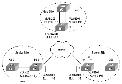
Figure 3-10 Network diagram for Hub&Spoke
III. Configuration procedure
& Note:
The following contents are omitted in this case: MPLS basic capacity configuration between PEs, configuration between PE and P, configuration between CEs. For the details refer to 3.4.1 .
1) Configure PE1
# Configure two VPN-instances on PE1, set specified VPN-target for the routes received from PE2 and PE3.
[PE1] ip vpn-instance vpn-instance2
[PE1-vpn-vpn-instance2] route-distinguisher 100:2
[PE1-vpn-vpn-instance2] vpn-target 100:11 import-extcommunity
[PE1-vpn-vpn-instance2] vpn-target 100:12 import-extcommunity
[PE1-vpn-instance2] quit
[PE1] ip vpn-instance vpn-instance3
[PE1-vpn-vpn-instance3] route-distinguisher 100:3
[PE1-vpn-vpn-instance3] vpn-target 100:2 export-extcommunity
[PE1-vpn-vpn-instance3] quit
# Set up EBGP adjacency between PE1 and CE1, import intra-CE1 VPN routes learned into MBGP VPN-instance address family, with one routing loop permitted.
[PE1] bgp 100
[PE1-bgp] ipv4-family vpn-instance vpn-instance2
[PE1-bgp-af-vpn-instance] import-route static
[PE1-bgp-af-vpn-instance] import-route direct
[PE1-bgp-af-vpn-instance] group 17216 external
[PE1-bgp-af-vpn-instance] peer 172.16.1.1 group 17216 as-number 65002
[PE1-bgp-af-vpn-instance] quit
[PE1-bgp] ipv4-family vpn-instance vpn-instance3
[PE1-bgp-af-vpn-instance] import-route static
[PE1-bgp-af-vpn-instance] import-route direct
[PE1-bgp-af-vpn-instance] group 17217 external
[PE1-bgp-af-vpn-instance] peer 172.17.1.1 group 17217 as-number 65002
[PE1-bgp-af-vpn-instance] peer 172.17.1.1 allow-as-loop 1
[PE1-bgp-af-vpn] quit
[PE1-bgp] quit
# Bind the VLAN interface connecting PE1 and CE1 to different VPN-instances. Bind the interface of the VLAN to which the Ethernet port Gigabitethernet 2/1/1 belongs to VPN-instance2, bind the interface of the VLAN to which the Ethernet port Gigabitethernet 2/1/2 belongs to VPN-instance3.
[PE1] vlan 201
[PE1-vlan201] port gigabitethernet 2/1/1
[PE1-vlan201] quit
[PE1] interface Vlan-interface 201
[PE1-Vlan-interface201] ip binding vpn-instance vpn-instance2
[PE1-Vlan-interface201] ip address 172.16.0.1 255.255.0.0
[PE1-Vlan-interface201] quit
[PE1] vlan 202
[PE1-vlan202] port gigabitethernet 2/1/2
[PE1-vlan202] quit
[PE1] interface Vlan-interface 202
[PE1-Vlan-interface202] ip binding vpn-instance vpn-instance3
[PE1-Vlan-interface202] ip address 172.17.0.1 255.255.0.0
[PE1-Vlan-interface202] quit
# Configure Loopback interface
[PE1] interface loopback 0
[PE1-LoopBack0] ip address 11.1.1.1 255.255.255.255
[PE1-LoopBack0] quit
# Set up MP-IBGP adjacency between PEs to exchange inter-PE VPN routing information and activate MP-IBGP peer in VPNv4 sub-address family view.
[PE1] bgp 100
[PE1-bgp] group 22
[PE1-bgp] peer 22.1.1.1 group 22 as-number 100
[PE1-bgp] peer 22.1.1.1 connect-interface loopback 0
[PE1-bgp] group 33
[PE1-bgp] peer 33.1.1.1 group 33 as-number 100
[PE1-bgp] peer 33.1.1.1 connect-interface loopback 0
[PE1-bgp] ipv4-family vpnv4
[PE1-bgp-af-vpn] peer 22 enable
[PE1-bgp-af-vpn] peer 22.1.1.1 group 22
[PE1-bgp-af-vpn] peer 33 enable
[PE1-bgp-af-vpn] peer 33.1.1.1 group 33
[PE1-bgp-af-vpn] quit
2) Configure PE2
# Create a VPN-instance on PE2, import VPN routing information of VPN-target 100:2 and advertise VPN routing information of VPN-target 100:1.
[PE2] ip vpn-instance vpn-instance1
[PE2-vpn-vpn-instance1] route-distinguisher 100:1
[PE2-vpn-vpn-instance1] vpn-target 100:11 export-extcommunity
[PE2-vpn-vpn-instance1] vpn-target 100:2 import-extcommunity
[PE2-vpn-vpn-instance1] quit
# Set up EBGP adjacency between PE2 and CE2, import intra-CE2 VPN routes learned into MBGP VPN-instance address family.
[PE2] bgp 100
[PE2-bgp] ipv4-family vpn-instance vpn-instance1
[PE2-bgp-af-vpn-instance] import-route static
[PE2-bgp-af-vpn-instance] import-route direct
[PE2-bgp-af-vpn-instance] group 172 external
[PE2-bgp-af-vpn-instance] peer 172.15.1.1 group 172 as-number 65003
[PE2-bgp-af-vpn-instance] quit
[PE2-bgp] quit
# Bind the interface of the VLAN to which the port connecting PE2 and CE2 belongs to VPN-instance.
[PE2] vlan 201
[PE2-vlan201] port gigabitethernet 2/1/1
[PE2-vlan201] quit
[PE2] interface Vlan-interface 201
[PE2-Vlan-interface201] ip binding vpn-instance vpn-instance1
[PE2-Vlan-interface201] ip address 172.15.0.1 255.255.0.0
[PE2-Vlan-interface201] quit
# Configure Loopback interface
[PE2] interface loopback 0
[PE2-LoopBack0] ip address 22.1.1.1 255.255.255.255
[PE2-LoopBack0] quit
# Set up MP-IBGP adjacency between PE2 and PE1 to exchange inter-PE VPN routing information and activate MP-IBGP peer in VPNv4 sub-address family view.
[PE2] bgp 100
[PE2] group 11
[PE2-bgp] peer 11.1.1.1 group 11 as-number 100
[PE2-bgp] peer 11.1.1.1 connect-interface loopback 0
[PE2-bgp] ipv4-family vpnv4
[PE2-bgp-af-vpn] peer 11 enable
[PE2-bgp-af-vpn] peer 11.1.1.1 allow-as-loop 1
[PE2-bgp-af-vpn] quit
[PE2-bgp] quit
3) Configure PE3
# Create a VPN-instance on PE3, import VPN routing information of VPN-target 100:2 and advertise VPN routing information of VPN-target 100:12.
[PE3] ip vpn-instance vpn-instance2
[PE3-vpn-vpn-instance2] route-distinguisher 100:4
[PE3-vpn-vpn-instance2] vpn-target 100:12 export-extcommunity
[PE3-vpn-vpn-instance2] vpn-target 100:2 import-extcommunity
[PE3-vpn-vpn-instance2] quit
# Set up EBGP adjacency between PE3 and CE3 import intra-CE3 VPN routes learned into MBGP VPN-instance address family.
[PE3] bgp 100
[PE3-bgp] ipv4-family vpn-instance vpn-instance2
[PE3-bgp-af-vpn-instance] import-route static
[PE3-bgp-af-vpn-instance] import-route direct
[PE3-bgp-af-vpn-instance] group 172 external
[PE3-bgp-af-vpn-instance] peer 172.18.1.1 group 172 as-number 65001
[PE3-bgp-af-vpn-instance] quit
[PE3-bgp] quit
# Bind the interface of the VLAN to which the port connecting PE3 and CE3 belongs to VPN-instance.
[PE3] vlan 201
[PE3-vlan201] port gigabitethernet 2/1/1
[PE3-vlan201] quit
[PE3] interface Vlan-interface 201
[PE3-Vlan-interface201] ip binding vpn-instance vpn-instance2
[PE3-Vlan-interface201] ip address 172.18.0.1 255.255.0.0
[PE3-Vlan-interface201] quit
# Configure Loopback interface
[PE3] interface loopback 0
[PE3-LoopBack0] ip address 33.1.1.1 255.255.255.255
[PE3-LoopBack0] quit
# Set up MP-IBGP adjacency between PE3 and PE1 to exchange inter-PE VPN routing information and activate MP-IBGP peer in VPNv4 sub-address family view.
[PE3] bgp 100
[PE3-bgp] group 11
[PE3-bgp] peer 11.1.1.1 group 11
[PE3-bgp] peer 11.1.1.1 connect-interface loopback 0
[PE3-bgp] ipv4-family vpnv4
[PE3-bgp-af-vpn] peer 11 enable
[PE2-bgp-af-vpn] peer 11.1.1.1 group 11
[PE2-bgp-af-vpn] peer 11.1.1.1 allow-as-loop 1
[PE3-bgp-af-vpn] quit
[PE3-bgp] quit
3.4.4 CE Dual-home Configuration Example
I. Network requirements
For the applications which require high robustness of network, you may use CE dual-home networking mode.
CE1 and CE2 are dual-homed; they are connected to both PE1 and PE2. Three PEs are connected to each other so the links between them are backed up. CE3 and CE4 are single-homed; each of them is only connected to one PE.
CE1 and CE3 are in one VPN, and CE2 and CE4 are in another VPN. The two VPNs cannot intercommunicate with each other.
II. Network diagram
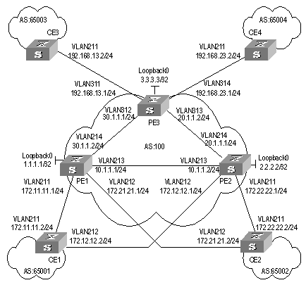
Figure 3-11 Network diagram for CE dual-home
III. Configuration procedure
& Note:
The configuration of CE router is omitted in this case and you can refer to Section 3.4.1 Integrated BGP/MPLS VPN Configuration .
1) Configure PE1
# Configure two VPN-instances 1.1 and 1.2 respectively for CE1 and CE2 on PE1, set different VPN-targets for them.
[PE1] ip vpn-instance vpn-instance1.1
[PE1-vpn-vpn-instance1.1] route-distinguisher 1.1.1.1:1
[PE1-vpn-vpn-instance1.1] vpn-target 1.1.1.1:1
[PE1-vpn-vpn-instance1.1] quit
[PE1] ip vpn-instance vpn-instance1.2
[PE1-vpn-vpn-instance1.2] route-distinguisher 2.2.2.2:2
[PE1-vpn-vpn-instance1.2] vpn-target 2.2.2.2:2
[PE1-vpn-vpn-instance1.2] quit
# Set up EBGP adjacency between PE1 and CE1 in VPN-instance 1, import intra-CE1 VPN routes learned into VPN-instance 1.1.
[PE1] bgp 100
[PE1-bgp] ipv4-family vpn-instance vpn-instance1.1
[PE1-bgp-af-vpn-instance] import-route direct
[PE1-bgp-af-vpn-instance] import-route static
[PE1-bgp-af-vpn-instance] group 17211 external
[PE1-bgp-af-vpn-instance] peer 172.11.11.2 group 17211 as-number 65001
[PE1-bgp-af-vpn-instance] quit
[PE1-bgp] quit
# Set up EBGP adjacency between PE1 and CE2 in VPN-instance 1.2, import intra-CE2 VPN routes learned into VPN-instance 1.2.
[PE1-bgp] ipv4-family vpn-instance vpn-instance1.2
[PE1-bgp-af-vpn-instance] import-route direct
[PE1-bgp-af-vpn-instance] import-route static
[PE1-bgp-af-vpn-instance] group 17221 external
[PE1-bgp-af-vpn-instance] peer 172.21.21.2 group 17221 as-number 65002
[PE1-bgp-af-vpn] quit
[PE1-bgp] quit
# Bind the interface connecting PE1 and CE1 to VPN-instance 1.1 and interface connecting PE1 and CE2 to VPN-instance 1.2.
[PE1] vlan 211
[PE1-vlan211] port gigabitethernet 2/1/1
[PE1-vlan211] quit
[PE1] interface Vlan-interface 211
[PE1-Vlan-interface211] ip binding vpn-instance vpn-instance1.1
[PE1-Vlan-interface211] ip address 172.11.11.1 255.255.255.0
[PE1-Vlan-interface211] quit
[PE1] vlan 212
[PE1-vlan212] port gigabitethernet 2/1/2
[PE1-vlan212] quit
[PE1] interface Vlan-interface 212
[PE1-Vlan-interface212] ip binding vpn-instance vpn-instance1.2
[PE1-Vlan-interface212] ip address 172.21.21.1 255.255.255.0
[PE1-Vlan-interface212] quit
# Configure Loopback interface
[PE1] interface loopback 0
[PE1-LoopBack0] ip address 1.1.1.1 255.255.255.255
[PE1-LoopBack0] quit
# Configure MPLS basic capacity, enable LDP on the interface connecting PE1 and PE2 and the interface connecting PE1 and PE3.
[PE1] mpls lsr-id 1.1.1.1
[PE1] mpls
[PE1-mpls] quit
[PE1] mpls ldp
[PE1] vlan 213
[PE1-vlan213] port gigabitethernet 2/1/3
[PE1-vlan213] quit
[PE1] interface Vlan-interface213
[PE1-Vlan-interface213] mpls
[PE1-Vlan-interface213] mpls ldp enable
[PE1-Vlan-interface213] mpls ldp transport-ip interface
[PE1-Vlan-interface213] ip address 10.1.1.1 255.255.255.0
[PE1-Vlan-interface213] quit
[PE1] vlan 214
[PE1-vlan214] port gigabitethernet 2/1/4
[PE1-vlan214] quit
[PE1] interface Vlan-interface 214
[PE1-Vlan-interface214] mpls
[PE1-Vlan-interface214] mpls ldp enable
[PE1-Vlan-interface214] mpls ldp transport-ip interface
[PE1-Vlan-interface214] ip address 30.1.1.2 255.255.255.0
[PE1-Vlan-interface214] quit
# Enable OSPF on the interface connecting PE1 and PE2 and the interface connecting PE1 and PE3 and the Loopback interface, to achieve inter-PE communication.
[PE1] Router-id 1.1.1.1
[PE1] ospf
[PE1-ospf-1] area 0
[PE1-ospf-1-area-0.0.0.0] network 1.1.1.1 0.0.0.0
[PE1-ospf-1-area-0.0.0.0] network 30.1.1.2 0.0.0.255
[PE1-ospf-1-area-0.0.0.0] network 10.1.1.1 0.0.0.255
[PE1-ospf-1-area-0.0.0.0] quit
[PE1-ospf-1] quit
# Set up MP-IBGP adjacency between PEs to exchange inter-PE VPN routing information and activate MP-IBGP peer in VPNv4 sub-address family view.
[PE1] bgp 100
[PE1-bgp] group 2
[PE1-bgp] peer 2.2.2.2 group 2
[PE1-bgp] peer 2.2.2.2 connect-interface loopback 0
[PE1-bgp] group 3
[PE1-bgp] peer 3.3.3.3 group 3
[PE1-bgp] peer 3.3.3.3 connect-interface loopback 0
[PE1-bgp] ipv4-family vpnv4
[PE1-bgp-af-vpn] peer 2 enable
[PE1-bgp-af-vpn] peer 2.2.2.2 group 2
[PE1-bgp-af-vpn] peer 3 enable
[PE1-bgp-af-vpn] peer 3.3.3.3 group 3
[PE1-bgp-af-vpn] quit
2) Configure PE2
& Note:
The configuration of PE2 is similar to that of PE1, so only VPN-instance configuration is detailed here.
# Create two VPN-instances 2.1 and 2.2 respectively for CE1 and CE2 on PE2, configure different VPN-targets for them.
[PE2] ip vpn-instance vpn-instance2.1
[PE2-vpn-vpn-instance2.1] route-distinguisher 1.1.1.1:1
[PE2-vpn-vpn-instance2.1] vpn-target 1.1.1.1:1
[PE2-vpn-vpn-instance2.1] quit
[PE2] ip vpn-instance vpn-instance2.2
[PE2-vpn-vpn-instance2.2] route-distinguisher 2.2.2.2:2
[PE2-vpn-vpn-instance2.2] vpn-target 2.2.2.2:2
[PE2-vpn-vpn-instance2.2] quit
# Set up EBGP adjacency between PE2 and CE1 in VPN-instance 2.1, import intra-CE1 VPN routes learned into VPN-instance2.1.
[PE2] bgp 100
[PE2-bgp] ipv4-family vpn-instance vpn-instance2.1
[PE2-bgp-af-vpn-instance] import-route direct
[PE2-bgp-af-vpn-instance] import-route static
[PE2-bgp-af-vpn-instance] group 17212 external
[PE2-bgp-af-vpn-instance] peer 172.12.12.2 group 17212 as-number 65001
[PE2-bgp-af-vpn] quit
# Set up EBGP adjacency between PE2 and CE2 in VPN-instance2.2, import intra-CE2 VPN routes learned into VPN-instance2.2.
[PE2-bgp] ipv4-family vpn-instance vpn-instance2.2
[PE2-bgp-af-vpn-instance] import-route direct
[PE2-bgp-af-vpn-instance] import-route static
[PE2-bgp-af-vpn-instance] group 17222 external
[PE2-bgp-af-vpn-instance] peer 172.22.22.2 group 17222 as-number 65002
[PE2-bgp-af-vpn] quit
[PE2-bgp] quit
# Bind the interface connecting PE2 and CE1 to VPN-instance 2.1 and the interface connecting PE2 and CE2 to VPN-instance 2.2.
[PE2] vlan 212
[PE2-vlan212] port gigabitethernet 2/1/2
[PE2-vlan212] quit
[PE2] interface Vlan-interface 212
[PE2-Vlan-interface212] ip binding vpn-instance vpn-instance2.1
[PE2-Vlan-interface212] ip address 172.12.12.1 255.255.255.0
[PE2-Vlan-interface212] quit
[PE2] vlan 211
[PE2-vlan211] port gigabitethernet 2/1/1
[PE2-vlan211] quit
[PE2] interface Vlan-interface 211
[PE2-Vlan-interface211] ip binding vpn-instance vpn-instance2.2
[PE2-Vlan-interface211] ip address 172.22.22.1 255.255.255.0
[PE2-Vlan-interface211] quit
3) Configure PE3
& Note:
Only the VPN-instance configuration of PE3 is detailed here, other configurations are similar to that of the PE1 and PE2, and are omitted here.
# Create two VPN-instances 3.1 and 3.2 respectively for CE3 and CE4 on PE3, configure different VPN-targets for them.
[PE3] ip vpn-instance vpn-instance3.1
[PE3-vpn-vpn-instance3.1] route-distinguisher 1.1.1.1:1
[PE3-vpn-vpn-instance3.1] vpn-target 1.1.1.1:1
[PE3-vpn-vpn-instance3.1] quit
[PE3] ip vpn-instance vpn-instance3.2
[PE3-vpn-instance] route-distinguisher 2.2.2.2:2
[PE3-vpn-instance] vpn-target 2.2.2.2:2
[PE3-vpn-instance] quit
# Set up EBGP adjacency between PE3 and CE3 in VPN-instance3.1, import intra-CE3 VPN routes learned into VPN-instance3.1.
[PE3] bgp 100
[PE3-bgp] ipv4-family vpn-instance vpn-instance3.1
[PE3-bgp-af-vpn-instance] import-route direct
[PE3-bgp-af-vpn-instance] import-route static
[PE3-bgp-af-vpn-instance] group 192 external
[PE3-bgp-af-vpn-instance] peer 192.168.13.2 group 192 as-number 65003
[PE3-bgp-af-vpn-instance] quit
[PE3-bgp] quit
# Set up EBGP adjacency between PE3 and CE4 in VPN-instance3.2, import intra-CE4 VPN routes learned into VPN-instance3.2.
[PE3-bgp] ipv4-family vpn-instance vpn-instance3.2
[PE3-bgp-af-vpn-instance] import-route direct
[PE3-bgp-af-vpn-instance] import-route static
[PE3-bgp-af-vpn-instance] group 232 external
[PE3-bgp-af-vpn-instance] peer 192.168.23.2 group 232 as-number 65004
[PE3-bgp-af-vpn-instance] quit
[PE3-bgp] quit
# Bind the interface connecting PE3 and CE3 to VPN-instance3.1 and the interface connecting PE3 and CE4 to VPN-instance 3.2.
[PE3] vlan 311
[PE3-vlan311] port gigabitethernet 3/1/1
[PE3-vlan311] quit
[PE3] interface Vlan-interface 311
[PE3-Vlan-interface311] ip binding vpn-instance vpn-instance3.1
[PE3-Vlan-interface311] ip address 192.168.13.1 255.255.255.0
[PE3-Vlan-interface311] quit
[PE3] vlan 314
[PE3-vlan314] port gigabitethernet 3/1/4
[PE3-vlan314] quit
[PE3] interface Vlan-interface 314
[PE3-Vlan-interface314] ip binding vpn-instance vpn-instance3.2
[PE3-Vlan-interface314] ip address 192.168.23.1 255.255.255.0
[PE3-Vlan-interface314] quit
3.4.5 Cross-domain BGP/MPLS VPN Configuration Example
I. Network requirements
A VPN subscriber has sites in both city A and B. Because of the geographical reason, site in City A accesses to the MPLS/VPN network of service provider in City A, and gets AS100 as the AS number; site in City B accesses to the MPLS/VPN network of service provider in City B, and gets AS200 as the AS number. The VPN goes through two ASs. CE1 and CE2 belong to VPN-A, while CE3 and CE4 belong to VPN-B.
II. Network diagram
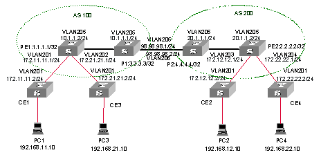
Figure 3-12 Network diagram for ASBR
III. Configuration procedure
1) Configure PE1
# Enable MPLS and LDP.
[PE1] mpls lsr-id 1.1.1.1
[PE1] mpls
[PE1-mpls] quit
[PE1] mpls ldp
# Configure the VLAN interface connecting CE.
[PE1] vlan 201
[PE1-vlan201] port gigabitethernet 2/1/1
[PE1-vlan201] quit
[PE1] vlan 202
[PE1-vlan202] port gigabitethernet 2/1/2
[PE1-vlan202] quit
# Configure Loopback interface.
[PE1] interface loopback 0
[PE1-LoopBack0] ip address 1.1.1.1 255.255.255.255
# Configure VPN-instance.
[PE1] ip vpn-instance vpna
[PE1-vpn-vpna] route-distinguisher 100:1
[PE1-vpn-vpna] vpn-target 100:1 both
[PE1] ip vpn-instance vpnb
[PE1-vpn-vpnb] route-distinguisher 100:2
[PE1-vpn-vpnb] vpn-target 100:2 both
# Configure VLAN interface connecting PE1 and P1.
[PE1] vlan 205
[PE1-vlan205] port gigabitethernet 2/2/1
[PE1-vlan205] quit
[PE1] interface Vlan-interface 205
[PE1-Vlan-interface205] mpls
[PE1-Vlan-interface205] mpls ldp enable
[PE1-Vlan-interface205] ip address 10.1.1.2 255.255.255.0
# Bind the VLAN interface with the VPN-instance.
[PE1] interface Vlan-interface 201
[PE1-Vlan-interface201] ip binding vpn-instance vpna
[PE1-Vlan-interface201] ip address 172.11.11.1 255.255.255.0
[PE1-Vlan-interface201] quit
[PE1] interface Vlan-interface 202
[PE1-Vlan-interface202] ip binding vpn-instance vpnb
[PE1-Vlan-interface202] ip address 172.21.21.1 255.255.255.0
[PE1-Vlan-interface202] quit
# Enable EBGP between PE and CE.
[PE1] bgp 100
[PE1-bgp] ipv4-family vpn-instance vpna
[PE1-bgp-af-vpn-instance] import-route direct
[PE1-bgp-af-vpn-instance] group 172-11 external
[PE1-bgp-af-vpn-instance] peer 172.11.11.2 group 172-11 as-number 65011
[PE1-bgp- af-vpn] quit
[PE1-bgp] ipv4-family vpn-instance vpnb
[PE1-bgp-af-vpn-instance] import-route direct
[PE1-bgp-af-vpn-instance] group 172-21 external
[PE1-bgp-af-vpn-instance] peer 172.21.21.2 group 172-21 as-number 65021
[PE1-bgp-af-vpn-instance] peer 172.21.21.2 next-hop-local
[PE1-bgp-af-vpn-instace] quit
# Enable MP-IBGP between PE-ASBRs.
[PE1-bgp] group 3 internal
[PE1-bgp] peer 3.3.3.3 group 3
[PE1-bgp] peer 3.3.3.3 connect-interface loopback0
[PE1-bgp] ipv4-family vpnv4
[PE1-bgp-af-vpn] peer 3 enable
[PE1-bgp-af-vpn] peer 3.3.3.3 group 3
[PE1-bgp-af-vpn] quit
[PE1-bgp] quit
2) Configure PE2
# Configure MPLS.
[PE2] mpls lsr-id 2.2.2.2
[PE2] mpls
[PE2-mpls] quit
[PE2] mpls ldp
# Configure the VLAN interface connecting CE.
[PE2] vlan 203
[PE2-vlan203] port gigabitethernet 2/1/1
[PE2-vlan203] quit
[PE2] vlan 204
[PE2-vlan204] port gigabitethernet 2/1/2
[PE2-vlan204] quit
# Configure Loopback interface.
[PE2] interface loopback 0
[PE2-LoopBack0] ip address 2.2.2.2 255.255.255.255
# Configure VPN-instance.
[PE2] ip vpn-instance vpna
[PE2-vpn-vpna] route-distinguisher 200:1
[PE2-vpn-vpna] vpn-target 100:1 both
[PE2] ip vpn-instance vpnb
[PE2-vpn-vpnb] route-distinguisher 200:2
[PE2-vpn-vpnb] vpn-target 100:2 both
# Configure the VLAN interface connecting PE2 and P2.
[PE1] vlan 205
[PE1-vlan205] port gigabitethernet 2/2/1
[PE1-vlan205] quit
[PE1] interface Vlan-interface 205
[PE1-Vlan-interface205] mpls
[PE1-Vlan-interface205] mpls ldp enable
[PE1-Vlan-interface205] ip address 20.1.1.2 255.255.255.0
# Bind the VLAN interface with the VPN-instance.
[PE2] interface Vlan-interface 203
[PE2-Vlan-interface203] ip binding vpn-instance vpna
[PE2-Vlan-interface203] ip address 172.12.12.1 255.255.255.0
[PE2-Vlan-interface203] quit
[PE2] interface Vlan-interface 204
[PE2-Vlan-interface204] ip binding vpn-instance vpnb
[PE2-Vlan-interface204] ip address 172.22.22.1 255.255.255.0
[PE2-Vlan-interface204] quit
# Enable EBGP between PE and CE.
[PE2] bgp 200
[PE2-bgp] ipv4-family vpn-instance vpna
[PE2-bgp-af-vpn-instance] import-route direct
[PE2-bgp-af-vpn-instance] group 172-12 external
[PE2-bgp-af-vpn-instance] peer 172.12.12.2 group 172-12 as-number 65012
[PE2-bgp] ipv4-family vpn-instance vpnb
[PE2-bgp-af-vpn-instance] import-route direct
[PE2-bgp-af-vpn-instance] group 172-22 external
[PE2-bgp-af-vpn-instance] peer 172.22.22.2 group 172-22 as-number 65022
[PE2-bgp-af-vpn-instance] quit
[PE2] quit
# Enable MB-IBGP between PE-ASBRs
[PE2-bgp] group 4
[PE2-bgp] peer 4.4.4.4 group 4
[PE2-bgp] peer 4.4.4.4 connect-interface loopback0
[PE2-bgp] ipv4-family vpnv4
[PE2-bgp-af-vpn] peer 4 enable
[PE2-bgp-af-vpn] peer 4.4.4.4 group 4
3) Configure P1 (P2 in similar way)
# Configure MPLS basic capability.
[P1] mpls lsr-id 3.3.3.3
[P1] mpls
[P1-mpls] quit
[P1] mpls ldp
# Configure the interface Loopback 0.
[P1] interface loopback 0
[P1-LoopBack0] ip address 3.3.3.3 255.255.255.255
# Configure VLAN interface connecting PE1.
[P1] vlan 205
[P1-vlan205] port gigabitethernet 2/1/1
[P1-vlan205] quit
[P1] interface Vlan-interface 205
[P1-Vlan-interface205] mpls
[P1-Vlan-interface205] mpls ldp enable
[P1-Vlan-interface205] ip address 10.1.1.1 255.255.255.0
[P1-Vlan-interface205] quit
# Configure VLAN interface connecting PE2.
[P1] vlan 206
[P1-vlan206] port gigabitethernet 2/1/2
[P1-vlan206] quit
[P1] interface Vlan-interface 206
[P1-Vlan-interface206] mpls
[P1-Vlan-interface206] mpls ldp enable
[P1-Vlan-interface206] ip address 98.98.98.1 255.255.255.0
[P1-Vlan-interface206] quit
# Configure IBGP neighbors and EBGP neighbors.
[P1] bgp 100
[P1-bgp] group 1 internal
[P1-bgp] peer 1.1.1.1 group 1
[P1-bgp] peer 1.1.1.1 connect-interface loopback0
[P1-bgp] group 4 external
[P1-bgp] peer 98.98.98.2 group 4 as-number 200
[P1-bgp] ipv4-family vpnv4
[P1-bgp-af-vpn] peer 1 enable
[P1-bgp-af-vpn] peer 1.1.1.1 group 1
[P1-bgp-af-vpn] peer 1 next-hop-local
[P1-bgp-af-vpn] peer 98 enable
[P1-bgp-af-vpn] peer 98.98.98.2 group 98
[P1-bgp-af-vpn] undo policy vpn-target
3.4.6 Cross-Domain BGP/MPLS VPN Configuration Example — Option C
I. Network requirements
CE1 and CE2 belong to the same VPN. CE1 accesses the MPLS network through PE1 in AS100; and CE2 accesses the MPLS network through PE2 in AS200.
The example adopts Option C to implement a cross-domain BGP/MPLS VPN, that is, the VPN routing is managed by the Multi-hop MP-EBGP which advertise label VPN-IPv4 routes between PEs.
II. Network diagram
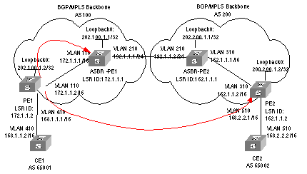
Figure 3-13 Network diagram for Multihop EBGP cross-domain VPN
III. Configuration procedure
l Configuring OSPF on the MPLS backbone network
l Configuring basic MPLS capability on the MPLS backbone network
l Configuring a VPN instance on PEs.
l Configuring MP-BGP
1) Configure OSPF as the IGP protocol on the MPLS backbone network; making OSPFs on PEs can learn routes from each other. Create OSPF neighbor between ASBR-PE and PE in the same AS.
# Configure PE1.
[PE1] interface loopback0
[PE1-LoopBack0] ip address 202.100.1.2 255.255.255.255
[PE1-LoopBack0] quit
[PE1] vlan 110
[PE1-vlan110] interface vlan-interface 110
[PE1-Vlan-interface110] ip address 172.1.1.2 255.255.0.0
[PE1-Vlan-interface110] quit
[PE1] ospf
[PE1-ospf-1] area 0
[PE1-ospf-1-area-0.0.0.0] network 172.1.0.0 0.0.255.255
[PE1-ospf-1-area-0.0.0.0] network 202.100.1.2 0.0.0.0
[PE1-ospf-1-area-0.0.0.0] quit
[PE1-ospf-1] quit
# Configure ASBR-PE1.
[ASBR-PE1] interface loopback0
[ASBR-PE1-LoopBack 0] ip address 202.100.1.1 255.255.255.255
[ASBR-PE1-LoopBack 0] quit
[ASBR-PE1] vlan 110
[ASBR-PE1-vlan110] interface vlan 110
[ASBR-PE1-Vlan-interface110] ip address 172.1.1.1 255.255.0.0
[ASBR-PE1-Vlan-interface110] quit
[ASBR-PE2] vlan 210
[ASBR-PE1-vlan210] interface vlan 210
[ASBR-PE1-Vlan-interface210] ip address 192.1.1.1 255.255.255.0
[ASBR-PE1-Vlan-interface210] quit
[ASBR-PE1] ospf
[ASBR-PE1-ospf-1] area 0
[ASBR-PE1-ospf-1-area-0.0.0.0] network 172.1.0.0 0.0.255.255
[ASBR-PE1-ospf-1-area-0.0.0.0] network 202.100.1.1 0.0.0.0
[ASBR-PE1-ospf-1-area-0.0.0.0] quit
[ASBR-PE1-ospf-1] quit
# Configure PE2.
[PE2] interface loopback0
[PE2-LoopBack0] ip address 202.200.1.2 255.255.255.255
[PE2-LoopBack0] quit
[PE2]vlan 310
[PE2-vlan310] interface vlan 310
[PE2-Vlan-interface310] ip address 162.1.1.2 255.255.0.0
[PE2- Vlan-interface310] quit
[PE2] ospf
[PE2-ospf-1] area 0
[PE2-ospf-1-area-0.0.0.0] network 162.1.0.0 0.0.255.255
[PE2-ospf-1-area-0.0.0.0] network 202.200.1.2 0.0.0.0
[PE2-ospf-1-area-0.0.0.0] quit
[PE2-ospf-1] quit
# Configure ASBR-PE2.
[ASBR-PE2] interface loopback0
[ASBR-PE2-LoopBack0] ip address 202.200.1.1 255.255.255.255
[ASBR-PE2-LoopBack0] quit
[ASBR-PE2] interface vlan 310
[ASBR-PE2-Vlan-interface310] ip address 162.1.1.1 255.255.0.0
[ASBR-PE2-Vlan-interface310] quit
[ASBR-PE2] vlan 210
[ASBR-PE2-vlan210] interface vlan 210
[ASBR-PE2-Vlan-interface210] ip address 192.1.1.2 255.255.255.0
[ASBR-PE2-Vlan-interface210] quit
[ASBR-PE2] ospf
[ASBR-PE2-ospf-1] area 0
[ASBR-PE2-ospf-1-area-0.0.0.0] network 162.1.0.0 0.0.255.255
[ASBR-PE2-ospf-1-area-0.0.0.0] network 202.200.1.1 0.0.0.0
[ASBR-PE2-ospf-1-area-0.0.0.0] quit
[ASBR-PE2-ospf-1] quit
2) Configure basic MPLS capability on the MPLS backbone network to enable the network to forward VPN traffic.
& Note:
MPLS must be enabled between the ASBR-PEs.
# Configure basic MPLS capability on PE1 and enable LDP on the interface connected to ASBR-PE1.
[PE1] mpls lsr-id 172.1.1.2
[PE1-mpls] lsp-trigger all
[PE1-mpls] quit
[PE1] mpls ldp
[PE1-mpls-ldp] quit
[PE1] interface vlan 110
[PE1-Vlan-interface110] mpls
[PE1-Vlan-interface110] mpls ldp
[PE1-Vlan-interface110] quit
# Configure basic MPLS capability on ASBR-PE1, enable LDP on the interface connected to PE1, and enable MPLS on the interface connected to ASBR-PE2.
[ASBR-PE1] mpls lsr-id 172.1.1.1
[ASBR-PE1-mpls] lsp-trigger all
[ASBR-PE1-mpls] quit
[ASBR-PE1] mpls ldp
[ASBR-PE1-mpls-ldp] quit
[ASBR-PE1] interface vlan 110
[ASBR-PE1-Vlan-interface110] mpls
[ASBR-PE1-Vlan-interface110] mpls ldp
[ASBR-PE1-Vlan-interface110] quit
[ASBR-PE1] interface vlan 210
[ASBR-PE1-Vlan-interface210] mpls
[ASBR-PE1-Vlan-interface210] quit
# Configure basic MPLS capability on ASBR-PE2, enable LDP on the interface connected to PE2, and enable MPLS on the interface connected to ASBR-PE1.
[ASBR-PE2] mpls lsr-id 162.1.1.1
[ASBR-PE2-mpls] lsp-trigger all
[ASBR-PE2-mpls] quit
[ASBR-PE2] mpls ldp
[ASBR-PE2-mpls-ldp] quit
[ASBR-PE2] interface vlan 310
[ASBR-PE2-Vlan-interface310] mpls
[ASBR-PE2-Vlan-interface310] mpls ldp
[ASBR-PE2-Vlan-interface310] quit
[ASBR-PE2] interface vlan 210
[ASBR-PE2-Vlan-interface210] mpls
[ASBR-PE2-Vlan-interface310] quit
# Configure basic MPLS capability on PE2 and enable LDP on the interface connected to ASBR-PE2.
[PE2] mpls lsr-id 162.1.1.2
[PE2-mpls] lsp-trigger all
[PE2-mpls] quit
[PE2] mpls ldp
[PE2-mpls-ldp] quit
[PE2] interface vlan 310
[PE2-Vlan-interface310] mpls
[PE2-Vlan-interface310] mpls ldp
[PE2-Vlan-interface310] quit
3) Create a VPN instance on each PE, and bind the instance to the interface connected to the corresponding CE.
# Configure CE1
[CE1] vlan 410
[CE1-vlan410] interface vlan 410
[CE1-Vlan-interface410] ip address 168.1.1.2 255.255.0.0
[CE1-Vlan-interface410] quit
# Create a VPN instance on PE1 and bind it to the interface connected to CE1
[PE1] ip vpn-instance vpna
[PE1-vpn-vpna] route-distinguisher 100:2
[PE1-vpn-vpna] vpn-target 100:1 both
[PE1-vpn-vpna] quit
[PE1]vlan 410
[PE1] interface vlan 410
[PE1-Vlan-interface410] ip binding vpn-instance vpna
[PE1-Vlan-interface410] ip address 168.1.1.1 255.255.0.0
[PE1-Vlan-interface410] quit
# Configure CE2
[CE2] vlan 510
[CE2-vlan510] interface vlan 510
[CE2-Vlan-interface510] ip address 168.2.2.2 255.255.0.0
[CE2-Vlan-interface510] quit
# Create a VPN instance on PE2 and bind it to the interface connected to CE2
[PE2] ip vpn-instance vpna
[PE2-vpn-instance] route-distinguisher 200:2
[PE2-vpn-instance] vpn-target 100:1 both
[PE2-vpn-instance] quit
[PE2] vlan 510
[PE2] interface vlan 510
[PE2-Vlan-interface510] ip binding vpn-instance vpna
[PE2-Vlan-interface510] ip address 168.2.2.1 255.255.0.0
[PE2-Vlan-interface510] quit
4) Configure MP-BGP, set up IBGP peer relation between PEs, and set up EBGP peer relation between PEs and their CEs.
& Note:
l Enable the exchanging of label-carried IPv4 route between the following routers: PE1 and ASBR-PE1, PE2 and ASBR-PE2, ASBR-PE1 and ASBR-PE2.
l Make each ASBR-PE change the next hop to its own when it advertises routes to the PE in the same AS.
l Configure routing policy on each ASBR-PE as follows: make the ASBR-PE assign MPLS label when it advertises a route received from the PE in this AS to the ASBR-PE in the peer AS, and let the ASBR-PE assign a new MPLS label when it advertises a label-carried IPv4 route to the PE in this AS.
# Configure CE1
[CE1] bgp 65001
[CE1-bgp] group 20 external
[CE1-bgp] peer 168.1.1.1 group 20 as-number 100
[CE1-bgp] quit
# Configure PE1: set up EBGP peer relation with CE1, IBGP peer relation with ASBR-PE1, and Multihop MP-EBGP peer relation with PE2.
[PE1] bgp 100
[PE1-bgp] ipv4-family vpn-instance vpna
[PE1-bgp-af-vpn-instance] group 10 external
[PE1-bgp-af-vpn-instance] peer 168.1.1.2 group 10 as-number 65001
[PE1-bgp-af-vpn-instance] import-route direct
[PE1-bgp-af-vpn-instance] quit
[PE1-bgp] group 20
[PE1-bgp] peer 20 label-route-capability
[PE1-bgp] peer 202.100.1.1 group 20
[PE1-bgp] peer 202.100.1.1 connect-interface loopback0
[PE1-bgp] group 30 external
[PE1-bgp] peer 30 ebgp-max-hop
[PE1-bgp] peer 200.200.1.2 group 30 as-number 200
[PE1-bgp] peer 200.200.1.2 connect-interface loopback0
[PE1-bgp] ipv4-family vpnv4
[PE1-bgp-af-vpn] peer 30 enable
[PE1-bgp-af-vpn] peer 200.200.1.2 group 30
[PE1-bgp-af-vpn] quit
[PE1-bgp] quit
# Configure ASBR-PE1: configure the route policy.
[ASBR-PE1] acl number 2001
[ASBR-PE1-acl-basic-2001] rule permit source 202.100.1.2 0
[ASBR-PE1-acl-basic-2001] rule deny source any
[ASBR-PE1-acl-basic-2001] quit
[ASBR-PE1] route-policy rtp-ebgp permit node 1
[ASBR-PE1-route-policy] if-match acl 2001
[ASBR-PE1-route-policy] apply mpls-label
[ASBR-PE1-route-policy] quit
[ASBR-PE1] route-policy rtp-ibgp permit node 10
[ASBR-PE1-route-policy] if-match mpls-label
[ASBR-PE1-route-policy] apply mpls-label
[ASBR-PE1-route-policy] quit
# Configure ASBR-PE1: set up EBGP peer relation with ASBR-PE2, and IBGP peer relation with PE1.
[ASBR-PE1] bgp 100
[ASBR-PE1-bgp] import-route ospf
[ASBR-PE1-bgp] group 10 external
[ASBR-PE1-bgp] peer 10 label-route-capability
[ASBR-PE1-bgp] peer 10 route-policy rtp-ebgp export
[ASBR-PE1-bgp] peer 192.1.1.2 group 10 as-number 200
[ASBR-PE1-bgp] group 20
[ASBR-PE1-bgp] peer 20 label-route-capability
[ASBR-PE1-bgp] peer 20 next-hop-local
[ASBR-PE1-bgp] peer 20 route-policy rtp-ibgp export
[ASBR-PE1-bgp] peer 202.100.1.2 group 20
[ASBR-PE1-bgp] peer 202.100.1.2 connect-interface loopback0
[ASBR-PE1-bgp] quit
# Configure CE2.
[CE2] bgp 65002
[CE2-bgp] group 10 external
[CE2-bgp] peer 168.2.2.1 group 10 as-number 200
[CE2-bgp] quit
# Configure PE2: set up EBGP peer relation with CE2, IBGP peer relation with ASBR-PE2, and Multihop MP-EBGP peer relation with PE1.
[PE2] bgp 200
[PE2-bgp] ipv4-family vpn-instance vpna
[PE2-bgp-af-vpn-instance] group 10 external
[PE2-bgp-af-vpn-instance] peer 168.2.2.2 group 10 as-number 65002
[PE2-bgp-af-vpn-instance] import-route direct
[PE2-bgp-af-vpn-instance] quit
[PE2-bgp] group 20
[PE2-bgp] peer 20 label-route-capability
[PE2-bgp] peer 202.200.1.1 group 20
[PE2-bgp] peer 202.200.1.1 connect-interface loopback0
[PE2-bgp] group 30 external
[PE2-bgp] peer 30 ebgp-max-hop
[PE2-bgp] peer 202.100.1.2 group 30 as-number 100
[PE2-bgp] peer 202.100.1.2 connect-interface loopback0
[PE2-bgp] ipv4-family vpnv4
[PE2-bgp-af-vpn] peer 30 enable
[PE2-bgp-af-vpn] peer 202.100.1.2 group 30
[PE2-bgp-af-vpn] quit
[PE2-bgp] quit
# Configure ASBR-PE2: configure the route policy.
[ASBR-PE2] acl number 2001
[ASBR-PE2-acl-basic-2001] rule permit source 200.200.1.2 0
[ASBR-PE2-acl-basic-2001] rule deny source any
[ASBR-PE2-acl-basic-2001] quit
[ASBR-PE2] route-policy rtp-ebgp permit node 1
[ASBR-PE2-route-policy] if-match acl 2001
[ASBR-PE2-route-policy] apply mpls-label
[ASBR-PE2-route-policy] quit
[ASBR-PE2] route-policy rtp-ibgp permit node 10
[ASBR-PE2-route-policy] if-match mpls-label
[ASBR-PE2-route-policy] apply mpls-label
[ASBR-PE2-route-policy] quit
# Configure ASBR-PE2: set up EBGP peer relation with ASBR-PE1, and IBGP peer relation with PE2.
[ASBR-PE2] bgp 200
[ASBR-PE2-bgp] import-route ospf
[ASBR-PE2-bgp] group 10 external
[ASBR-PE2-bgp] peer 10 label-route-capability
[ASBR-PE2-bgp] peer 10 route-policy rtp-ebgp export
[ASBR-PE2-bgp] peer 192.1.1.1 group 10 as-number 100
[ASBR-PE2-bgp] group 20
[ASBR-PE2-bgp] peer 20 label-route-capability
[ASBR-PE2-bgp] peer 20 next-hop-local
[ASBR-PE2-bgp] peer 20 route-policy rtp-ibgp export
[ASBR-PE2-bgp] peer 202.200.1.2 group 20
[ASBR-PE2-bgp] peer 202.200.1.2 connect-interface loopback0
3.4.7 Hierarchical BGP/MPLS VPN Configuration Example
I. Network requirements
For those VPNs that have distinct hierarchy, an MPLS VPN covering a province and its cities, for example, incorporating the backbone network at the province level and the networks at the city level into a single MPLS VPN will impose a high requirement in performance on the equipment on the entire network, in the event that the network topology size is large. However, the requirement in equipment performance can become lower if this MPLS VPN is separated into two VPNs, the network at the province level and the network at the city level, for example.
SPE acts as a PE on the network at the province level, and is connected with a downstream MPLS VPN at the city level. UPE acts as a PE on the network at the city level and provide access service for the VPN clients which are normally low-end routers.
II. Network diagram
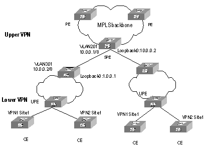
Figure 3-14 Network diagram for hierarchical BGP/MPLS VPN
III. Configuration procedure
& Note:
This case only illustrates the configurations concerned with PEs in a hierarchical BGP/MPLS VPN.
1) Configure SPE
# Configure the basic MPLS capability.
[SPE] mpls lsr-id 1.0.0.2
[SPE] mpls
[SPE-mpls] quit
[SPE] mpls ldp
# Configure VPN-instance
[SPE] ip vpn-instance vpn1
[SPE-vpn-vpn1] route-distinguisher 100:1
[SPE-vpn-vpn1] vpn-target 100:1 both
# Configure interfaces (So far as a PE router concerned, its Loopback 0 interface must be assigned with a host address of 32-bit mask.
[SPE] vlan 201
[SPE-vlan201] port gigabitethernet 2/1/1
[SPE-vlan201] quit
[SPE] interface Vlan-interface 201
[SPE-Vlan-interface201] ip address 10.0.0.1 255.0.0.0
[SPE-Vlan-interface201] mpls
[SPE-Vlan-interface201] mpls ldp enable
[SPE-Vlan-interface201] quit
[SPE] interface loopback0
[SPE-LoopBack 0] ip address 1.0.0.2 255.255.255.255
[SPE-LoopBack 0] quit
# Configure BGP
[SPE] bgp 100
[SPE] import direct
[SPE-bgp] group 1 internal
[SPE-bgp] peer 1.0.0.1 group 1
[SPE-bgp] peer 1 connect-interface LoopBack0
[SPE-bgp] ipv4-family vpn-instance vpn1
[SPE--bgp-af-vpn-instance] import direct
[SPE--bgp-af-vpn-instance] quit
[SPE-bgp] ipv4-family vpnv4
[SPE-bgp-af-vpn] peer 1 enable
[SPE-bgp-af-vpn] peer 1.0.0.1 group 1
[SPE-bgp-af-vpn] peer 1.0.0.1 upe
[SPE-bgp-af-vpn] peer 1.0.0.1 default-route-advertise vpn-instance vpn1
[SPE-bgp-af-vpn] quit
[SPE-bgp] quit
# Configure OSPF
[SPE] ospf
[SPE] import-route direct
[SPE-ospf-1] area 0
[SPE-ospf-1-area-0.0.0.0] network 1.0.0.2 0.0.0.0
[SPE-ospf-1-area-0.0.0.0] network 10.0.0.0 0.255.255.255
2) Configure UPE
# Configure the basic MPLS capability.
[UPE] mpls lsr-id 1.0.0.1
[UPE] mpls
[UPE-mpls] quit
[UPE] mpls ldp
# Configure VPN-instance
[UPE] ip vpn-instance vpn1
[UPE-vpn-vpn1] route-distinguisher 100:1
[UPE-vpn-vpn1] vpn-target 100:1 both
# Configure interfaces
[UPE] vlan 301
[UPE-vlan301] port gigabitethernet 2/2/1
[UPE-vlan301] quit
[UPE] interface Vlan-interface 301
[UPE-Vlan-interface301] mpls
[UPE-Vlan-interface301] mpls ldp enable
[UE1-Vlan-interface301] mpls ldp transport-ip interface
[UPE-Vlan-interface301] ip address 10.0.0.2 255.0.0.0
[UPE-Vlan-interface301] quit
[UPE] interface loopback0
[UPE-LoopBack 0] ip address 1.0.0.1 255.255.255.255
# Configure BGP
[UPE] bgp 100
[UPE-bgp] group 1 internal
[UPE-bgp] peer 1.0.0.2 group 1
[UPE-bgp] ipv4-family vpn-instance vpn1
[UPE--bgp-af-vpn-instance] import direct
[UPE-bgp] ipv4-family vpnv4
[UPE-bgp-af-vpn] peer 1 enable
[UPE-bgp-af-vpn] peer 1.0.0.2 group 1
# Configure OSPF
[UPE] ospf
[UPE-ospf-1] import-route direct
[UPE-ospf-1] area 0
[UPE-ospf-1-area-0.0.0.0] network 1.0.0.1 0.0.0.0
[UPE-ospf-1-area-0.0.0.0] network 10.0.0.2 0.255.255.255
[UPE-ospf-1-area-0.0.0.0] quit
3.4.8 OSPF Multi-instance Sham-link Configuration Example
I. Network requirements
As shown in the following picture, a company connects to a WAN through OSPF multi-instance function of H3C router. OSPF is bind to VPN1.MPLS VPN backbone runs between PEs and OSPF runs between PE and CE. Configure a Sham-link between PE1 and PE2 to ensure the traffic between CE1 and CE2 does not pass the Backdoor link that directly connects CE1 and CE2.
II. Network diagram
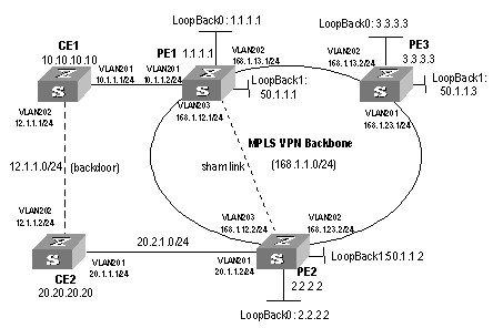
Figure 3-15 Network diagram for OSPF multi-instance
III. Configuration procedure
1) Configure PE1
# Enable MPLS and LDP.
[PE1] mpls lsr-id 50.1.1.1
[PE1] mpls
[PE1-mpls] quit
[PE1] mpls ldp
# Configure VPN-instance.
[PE1] ip vpn-instance vpn1
[PE1-vpn-vpn1] route-distinguisher 2:1
[PE1-vpn-vpn1] vpn-target 100:1 export-extcommunity
[PE1-vpn-vpn1] vpn-target 100:1 import-extcommunity
# Configure VLAN interface.
[PE1] vlan 203
[PE1-vlan203] port gigabitethernet 2/1/3
[PE1-vlan203] quit
[PE1] interface Vlan-interface 203
[PE1-Vlan-interface203] ip address 168.1.12.1 255.255.255.0
[PE1-Vlan-interface203] mpls
[PE1-Vlan-interface203] mpls ldp enable
[PE1-Vlan-interface203] quit
[PE1] vlan 201
[PE1-vlan201] port gigabitethernet 2/1/1
[PE1-vlan201] quit
[PE1] interface Vlan-interface 201
[PE1-Vlan-interface201] ip binding vpn-instance vpn1
[PE1-Vlan-interface201] ip address 10.1.1.2 255.255.255.0
[PE1-Vlan-interface201] ospf cost 1
[PE1-Vlan-interface201] quit
[PE1] vlan 202
[PE1-vlan202] port gigabitethernet 2/1/2
[PE1-vlan202] quit
[PE1] interface Vlan-interface 202
[PE1-Vlan-interface202] ip address 168.1.13.1 255.255.255.0
[PE1-Vlan-interface202] ospf cost 1
[PE1-Vlan-interface202] mpls
[PE1-Vlan-interface202] mpls ldp enable
[PE1-Vlan-interface202] mpls ldp transport-ip interface
[PE1-Vlan-interface202] quit
[PE1] interface loopback0
[PE1-LoopBack0] ip binding vpn-instance vpn1
[PE1-LoopBack0] ip address 1.1.1.1 255.255.255.255
[PE1-LoopBack0] quit
[PE1] interface loopback1
[PE1-LoopBack1] ip address 50.1.1.1 255.255.255.255
# Configure BGP Peer.
[PE1] bgp 100
[PE1-bgp] undo synchronization
[PE1-bgp] group fc internal
[PE1-bgp] peer 50.1.1.2 group fc
[PE1-bgp] peer 50.1.1.2 connect-interface LoopBack1
[PE1-bgp] peer 50.1.1.3 group fc
# Configure BGP and import OSPF routing and direct-connect route.
[PE1-bgp] ipv4-family vpn-instance vpn1
[PE1-bgp-af-vpn-instance] import-route ospf 100
[PE1-bgp-af-vpn-instance] import-route ospf-ase 100
[PE1-bgp-af-vpn-instance] import-route ospf-nssa 100
[PE1-bgp-af-vpn-instance] import-route direct
[PE1-bgp-af-vpn-instance] undo synchronization
# Create and activate Peer in MBGP.
[PE1-bgp-af-vpn] ipv4-family vpnv4
[PE1-bgp-af-vpn] peer fc enable
[PE1-bgp-af-vpn] peer fc advertise-community
[PE1-bgp-af-vpn] peer 50.1.1.2 group fc
# Bind OSPF process to VPN-instance.
[PE1] ospf 100 router-id 1.1.1.1 vpn-instance vpn1
[PE1-ospf-100] import-route bgp
[PE1-ospf-100] area 0.0.0.0
[PE1-ospf-100-area-0.0.0.0] network 10.1.1.0 0.0.0.255
# Configuring Sham-link
[PE1-ospf-100-area-0.0.0.1] sham-link 1.1.1.1 2.2.2.2
# Configure the routes distributed to PE2 and PE3.
[PE1] ospf 1000
[PE1-ospf-1000] area 0
[H3C-ospf-1000-area-0.0.0.0] network 168.12.1.0 0.0.0.255
[H3C-ospf-1000-area-0.0.0.0] network 50.1.1.1 0.0.0.0
2) Configure PE2
# Enable MPLS and LDP.
[PE2] mpls lsr-id 50.1.1.2
[PE2] mpls
[PE2-mpls] quit
[PE2] mpls ldp
# Configure VPN-instance VPN1.
[PE2] ip vpn-instance vpn1
[PE2-vpn-vpn1] route-distinguisher 2:1
[PE2-vpn-vpn1] vpn-target 100:1 export-extcommunity
[PE2-vpn-vpn1] vpn-target 100:1 import-extcommunity
# Configure VLAN interface.
[PE2] vlan 203
[PE2-vlan203] port gigabitethernet 2/1/3
[PE2-vlan203] quit
[PE2] interface Vlan-interface 203
[PE2-Vlan-interface203] ip address 168.1.12.2 255.255.255.0
[PE2-Vlan-interface203] mpls
[PE2-Vlan-interface203] mpls ldp enable
[PE2-Vlan-interface203] quit
[PE2] vlan 201
[PE2-vlan201] port gigabitethernet 2/1/1
[PE2-vlan201] quit
[PE2] interface Vlan-interface 201
[PE2-Vlan-interface201] ip binding vpn-instance vpn1
[PE2-Vlan-interface201] ip address 20.1.1.2 255.255.255.0
[PE2-Vlan-interface201] ospf cost 1
[PE2-Vlan-interface201] quit
[PE2] vlan 202
[PE2-vlan202] port gigabitethernet 2/1/2
[PE2-vlan202] quit
[PE2] interface Vlan-interface 202
[PE2-Vlan-interface202] ip address 168.1.23.2 255.255.255.0
[PE2-Vlan-interface202] ospf cost 1
[PE2-Vlan-interface202] mpls
[PE2-Vlan-interface202] mpls ldp enable
[PE2-Vlan-interface202] quit
[PE2] interface LoopBack0
[PE2-LoopBack0] ip binding vpn-instance vpn1
[PE2-LoopBack0] ip address 2.2.2.2 255.255.255.255
[PE2-LoopBack0] quit
[PE2] interface LoopBack1
[PE2-LoopBack1] ip address 50.1.1.2 255.255.255.255
# Configure BGP.
[PE2] bgp 100
[PE2-bgp] undo synchronization
[PE2-bgp] group fc internal
[PE2-bgp] peer 50.1.1.1 group fc
[PE2-bgp] peer 50.1.1.1 connect-interface LoopBack1
[PE2-bgp] peer 50.1.1.3 group fc
# Configure VPN-instance and import OSPF and direct-connect route.
[PE2-bgp] ipv4-family vpn-instance vpn1
[PE2-bgp-af-vpn-instance] import-route direct
[PE2-bgp-af-vpn-instance] import-route ospf-nssa 100
[PE2-bgp-af-vpn-instance] import-route ospf-ase 100
[PE2-bgp-af-vpn-instance] import-route ospf 100
[PE2-bgp-af-vpn-instance] undo synchronization
# Configure MBGP and enable Peer.
[PE2-bgp-af-vpn] ipv4-family vpnv4
[PE2-bgp-af-vpn] peer fc enable
[PE2-bgp-af-vpn] peer fc advertise-community
[PE2-bgp-af-vpn] peer 50.1.1.1 group fc
# Configure OSPF and import BGP and direct-connect route.
[PE2] ospf 100 router-id 2.2.2.2 vpn-instance vpn1
[PE2-ospf-100] import-route bgp
[PE2-ospf-100] import-route static
[PE2-ospf-100] area 0.0.0.0
[PE2-ospf-100-area-0.0.0.0] network 20.1.1.0 0.0.0.255
# Configuring Sham-link
[PE2-ospf-100-area-0.0.0.0] sham-link 2.2.2.2 1.1.1.1
# Configure static route to PE1 and PE3.
[PE2] ip route-static 50.1.1.1 255.255.255.255 168.1.12.1
[PE2] ip route-static 50.1.1.3 255.255.255.255 168.1.23.3
# Configure the routes distributed to PE1 and PE3.
[PE1] ospf 1000
[PE1-ospf-1000]area 0
[H3C-ospf-1000-area-0.0.0.0] network 168.12.1.0 0.0.0.255
[H3C-ospf-1000-area-0.0.0.0] network 50.1.1.1 0.0.0.0
3) Configure CE1.
# Configure interfaces
[CE1] vlan 202
[CE1-vlan202] port gigabitethernet 2/1/2
[CE1-vlan202] quit
[CE1] interface Vlan-interface 202
[CE1-Vlan-interface202] ip address 12.1.1.1 255.255.255.0
[CE1-Vlan-interface202] ospf cost 100
[CE1-Vlan-interface202] quit
[CE1] vlan 201
[CE1-vlan201] port gigabitethernet 2/1/1
[CE1-vlan201] quit
[CE1] interface Vlan-interface 201
[CE1-Vlan-interface201] ip address 10.1.1.1 255.255.255.0
[CE1-Vlan-interface201] ospf cost 1
# Configure OSPF.
[CE1] ospf 100 router-id 10.10.10.129
[CE1-ospf-100] import-route direct
[CE1-ospf-100] area 0.0.0.0
[CE1-ospf-100-area-0.0.0.0] network 10.1.1.0 0.0.0.255
[CE1-ospf-100-area-0.0.0.0] network 12.1.1.0 0.0.0.255
4) Configure CE2
# Configure interface.
[CE2] vlan 202
[CE2-vlan202] port gigabitethernet 2/1/2
[CE2-vlan202] quit
[CE2] interface Vlan-interface 202
[CE2-Vlan-interface202] ip address 12.1.1.2 255.255.255.0
[CE2-Vlan-interface202] ospf cost 100
[CE2-Vlan-interface202] quit
[CE2] vlan 201
[CE2-vlan201] port gigabitethernet 2/1/1
[CE2-vlan201] quit
[CE2] interface Vlan-interface 201
[CE2-Vlan-interface201] ip address 20.1.1.1 255.255.255.0
[CE2-Vlan-interface201] ospf cost 1
# Configure OSPF.
[CE2] ospf 100 router-id 20.20.20.20
[CE2-ospf-100] area 0.0.0.0
[CE2-ospf-100-area-0.0.0.0] network 12.1.1.0 0.0.0.255
[CE2-ospf-100-area-0.0.0.0] network 20.1.1.0 0.0.0.255
3.4.9 Nested BGP/MPLS VPN Configuration Example
I. Network requirements
A VPN user has multiple nodes to access the service provider's BGP/MPLS backbone network. And this VPN is divided into three sub-VPNs: VPN1, VPN2 and VPN3.
Some of the nodes of these sub-VPNs directly access a PE in the network, and some access a PE through the father VPN. That is, the adopted network structure is unsymmetrical.
This example mainly describes the configuration of VPN1; the configuration of other sub-VPNs is similar.
II. Network diagram

Figure 3-16 Network diagram for nested VPN
III. Configuration procedure
& Note:
This procedure omits part of the configuration for CE router.
1) Configure IGP on the service provider's backbone network.
# Configure prov_pe1.
<H3C> system-view
[H3C] sysname prov_pe1
[prov_pe1] interface LoopBack0
[prov_pe1-LoopBack0] ip address 5.5.5.5 255.255.255.255
[prov_pe1-LoopBack0] quit
[prov_pe1] vlan 110
[prov_pe1-vlan110] interface vlan 110
[prov_pe1-Vlan-interface110] ip address 10.1.1.1 255.0.0.0
[prov_pe1-Vlan-interface110] quit
[prov_pe1] ospf
[prov_pe1-ospf] area 0
[prov_pe1-ospf-area-0.0.0.0] network 5.5.5.5 0.0.0.0
[prov_pe1-ospf-area-0.0.0.0] network 10.0.0.0 0.255.255.255
# Configure prov_pe2.
<H3C> system-view
[H3C] sysname prov_pe2
[prov_pe2] interface LoopBack0
[prov_pe2-LoopBack0] ip address 4.4.4.4 255.255.255.255
[prov_pe2-LoopBack0] quit
[prov_pe1] vlan 110
[prov_pe1-vlan110] interface vlan-interface 110
[prov_pe1-Vlan-interface110] ip address 10.1.1.2 255.0.0.0
[prov_pe1-Vlan-interface110] quit
[prov_pe2] ospf
[prov_pe2-ospf] area 0
[prov_pe2-ospf-area-0.0.0.0] network 4.4.4.4 0.0.0.0
[prov_pe2-ospf-area-0.0.0.0] network 10.0.0.0 0.255.255.255
Configure basic MPLS capability and MPLS LDP on the backbone network.
# Configure prov_pe1.
[prov_pe1] mpls lsr-id 5.5.5.5
[prov_pe1] mpls ldp
[prov_pe1] interface vlan 110
[prov_pe1- Vlan-interface110] mpls
[prov_pe1- Vlan-interface110] mpls ldp
[prov_pe1- Vlan-interface110] quit
# Configure prov_pe2.
[prov_pe2] mpls lsr-id 4.4.4.4
[prov_pe2] mpls ldp
[prov_pe2] interface vlan 110
[prov_pe2- Vlan-interface110] mpls
[prov_pe2- Vlan-interface110] mpls ldp
[prov_pe2- Vlan-interface110] quit
Configure IBGP between provider PEs.
# Configure prov_pe1.
[prov_pe1] bgp 100
[prov_pe1-bgp] group ibgp internal
[prov_pe1-bgp] peer 4.4.4.4 group ibgp
[prov_pe1-bgp] peer 4.4.4.4 connect-interface LoopBack0
[prov_pe1-bgp] ipv4-family vpnv4
[prov_pe1-bgp-af-vpn] peer ibgp enable
[prov_pe1-bgp-af-vpn] peer ibgp next-hop-local
[prov_pe1-bgp-af-vpn] peer 4.4.4.4 group ibgp
[prov_pe1-bgp-af-vpn] quit
[prov_pe1-bgp] quit
# Configure prov_pe2.
[prov_pe2] bgp 100
[prov_pe2-bgp] group ibgp internal
[prov_pe2-bgp] peer 5.5.5.5 group ibgp
[prov_pe2-bgp] peer 5.5.5.5 connect-interface LoopBack0
[prov_pe2-bgp] ipv4-family vpnv4
[prov_pe2-bgp-af-vpn] peer ibgp enable
[prov_pe2-bgp-af-vpn] peer ibgp next-hop-local
[prov_pe2-bgp-af-vpn] peer 5.5.5.5 group ibgp
[prov_pe2-bgp-af-vpn] quit
[prov_pe2-bgp] quit
2) Create a VPN instance on provider PEs to access customer PEs and directly connected user CEs.
# Configure prov_pe1.
[prov_pe1] ip vpn-instance customer_vpn
[prov_pe1-vpn-instance] route-distinguisher 3:3
[prov_pe1-vpn-instance] vpn-target 3:3 export-community
[prov_pe1-vpn-instance] quit
[prov_pe1] ip vpn-instance vpn1
[prov_pe1-vpn-instance] route-distinguisher 1:1
[prov_pe1-vpn-instance] vpn-target 1:1
[prov_pe1-vpn-instance] vpn-target 3:3
[prov_pe1-vpn-instance] quit
[prov_pe1] vlan 310
[prov_pe1] interface vlan 310
[prov_pe1-Vlan-interface310] ip binding vpn-instance customer_vpn
[prov_pe1-Vlan-interface310] ip address 1.1.1.2 255.0.0.0
[prov_pe1- Vlan-interface310] mpls
[prov_pe1- Vlan-interface310] quit
[prov_pe1] interface vlan 210
[prov_pe1-Vlan-interface210] ip binding vpn-instance vpn1
[prov_pe1- Vlan-interface210] ip address 18.1.1.1 255.0.0.0
[prov_pe1- Vlan-interface210] quit
# Configure prov_pe2.
[prov_pe2] ip vpn-instance customer_vpn
[prov_pe2-vpn-instance] route-distinguisher 3:3
[prov_pe2-vpn-instance] vpn-target 3:3
[prov_pe2-vpn-instance] quit
[prov_pe2] interface vlan 410
[prov_pe2-Vlan-interface410] ip binding vpn-instance customer_vpn
[prov_pe2- Vlan-interface410] ip address 2.1.1.2 255.0.0.0
[prov_pe2- Vlan-interface410] mpls
[prov_pe2- Vlan-interface410] quit
# Configure cust_pe1.
<H3C> system-view
[H3C] sysname cust_pe1
[cust_pe1] interface LoopBack0
[cust_pe1-LoopBack0] ip address 6.6.6.6 255.255.255.255
[cust_pe1-LoopBack0] quit
[cust_pe1] mpls lsr-id 6.6.6.6
[cust_pe1] interface vlan 310
[cust_pe1-Vlan-interface310] ip address 1.1.1.1 255.0.0.0
[cust_pe1- Vlan-interface310] mpls
[cust_pe1- Vlan-interface310] quit
# Configure cust_pe2.
<H3C> system-view
[H3C] sysname cust_pe2
[cust_pe2] interface LoopBack0
[cust_pe2-LoopBack0] ip address 7.7.7.7 255.255.255.255
[cust_pe2-LoopBack0] quit
[cust_pe2] mpls lsr-id 7.7.7.7
[cust_pe2] interface vlan 410
[cust_pe2-Vlan-interface410] ip address 2.1.1.1 255.0.0.0
[cust_pe2-Vlan-interface410] mpls
[cust_pe2-Vlan-interface410] quit
3) Configure EBGP between provider PE and customer PE.
# Configure prov_pe1 to access the corresponding Customer PE.
[prov_pe1] route-policy comm permit node 10
[prov_pe1-route-policy-comm-10] if-match vpn-target 1:1
[prov_pe1-route-policy-comm-10] quit
[prov_pe1] bgp 100
[prov_pe1-bgp] ipv4-family vpn-instance customer_vpn
[prov_pe1-bgp-af-vpn-instance] group ebgp external
[prov_pe1-bgp-af-vpn-instance] undo peer ebgp enable
[prov_pe1-bgp-af-vpn-instance] peer 1.1.1.1 group ebgp as-number 600
[prov_pe1-bgp] ipv4-family vpnv4
[prov_pe1-bgp-af-vpn] nesting-vpn
[prov_pe1-bgp-af-vpn] peer ebgp vpn-instance customer_vpn enable
[prov_pe1-bgp-af-vpn] peer 1.1.1.1 vpn-instance customer_vpn group ebgp
[prov_pe1-bgp-af-vpn] peer 1.1.1.1 vpn-instance customer_vpn route-policy comm import
[prov_pe1-bgp-af-vpn] quit
# Configure prov_pe1 to access CE5
[prov_pe1-bgp] ipv4-family vpn-instance vpn1
[prov_pe1-bgp-af-vpn-instance] group ebgp external
[prov_pe1-bgp-af-vpn-instance] peer 18.1.1.2 group ebgp as-number 50003
# Configure prov_pe2 to access the corresponding Customer PE.
[prov_pe2] route-policy com2 permit node 10
[prov_pe2-route-policy-com2-10] if-match vpn-target 1:1
[prov_pe2-route-policy-com2-10] quit
[prov_pe2] bgp 100
[prov_pe2-bgp] ipv4-family vpn-instance customer_vpn
[prov_pe2-bgp-af-vpn-instance] group ebgp external
[prov_pe2-bgp-af-vpn-instance] undo peer ebgp enable
[prov_pe2-bgp-af-vpn-instance] peer 2.1.1.1 group ebgp as-number 500
[prov_pe2-bgp] ipv4-family vpnv4
[prov_pe2-bgp-af-vpn] nesting-vpn
[prov_pe2-bgp-af-vpn] peer ebgp vpn-instance customer_vpn enable
[prov_pe2-bgp-af-vpn] peer 2.1.1.1 vpn-instance customer_vpn group ebgp
[prov_pe2-bgp-af-vpn] peer 2.1.1.1 vpn-instance customer_vpn route-policy com2 import
# Configure cust_pe1
[cust_pe1] bgp 600
[cust_pe1-bgp] group ebgp external
[cust_pe1-bgp] undo peer ebgp enable
[cust_pe1-bgp] peer 1.1.1.2 group ebgp as-number 100
[cust_pe1-bgp] ipv4-family vpnv4
[cust_pe1-bgp-af-vpn] peer ebgp enable
[cust_pe1-bgp-af-vpn] peer 1.1.1.2 group ebgp
# Configure cust_pe2
[cust_pe2] bgp 500
[cust_pe2-bgp] group ebgp external
[cust_pe2-bgp] undo peer ebgp enable
[cust_pe2-bgp] peer 2.1.1.2 group ebgp as-number 100
[cust_pe2-bgp] ipv4-family vpnv4
[cust_pe2-bgp-af-vpn] peer ebgp enable
[cust_pe2-bgp-af-vpn] peer 2.1.1.2 group ebgp
4) On each Customer PE, configure the sub-VPN that accesses the network through the Customer PE.
# Configure cust_pe1.
[cust_pe1] ip vpn-instance vpn1
[cust_pe1-vpn-instance] route-distinguisher 1:1
[cust_pe1-vpn-instance] vpn-target 1:1
[cust_pe1-vpn-instance] quit
[cust_pe1] interface vlan 510
[cust_pe1-Vlan-interface510] ip binding vpn-instance vpn1
[cust_pe1- Vlan-interface510] ip address 15.1.1.2 255.0.0.0
[cust_pe1-Vlan-interface510] quit
[cust_pe1] bgp 600
[cust_pe1-bgp] undo peer ebgp enable
[cust_pe1-bgp] ipv4-family vpn-instance vpn1
[cust_pe1-bgp-af-vpn-instance] group cegroup external
[cust_pe1-bgp-af-vpn-instance] peer 15.1.1.1 group cegroup as-number 50001
[cust_pe1-bgp-af-vpn-instance] quit
[cust_pe1-bgp] quit
# Configure cust_pe2
[cust_pe2] ip vpn-instance vpn1
[cust_pe2-vpn-instance] route-distinguisher 1:1
[cust_pe2-vpn-instance] vpn-target 1:1
[cust_pe2] interface vlan 610
[cust_pe2-Vlan-interface610] ip binding vpn-instance vpn1
[cust_pe2-Vlan-interface610] ip address 16.1.1.2 255.0.0.0
[cust_pe2-Vlan-interface510] quit
[cust_pe2] bgp 500
[cust_pe2-bgp] undo peer ebgp enable
[cust_pe2-bgp] ipv4-family vpn-instance vpn1
[cust_pe2-bgp-af-vpn-instance] group cegroup external
[cust_pe2-bgp-af-vpn-instance] peer 16.1.1.1 group cegroup as-number 50002
[cust_pe2-bgp-af-vpn-instance] quit
[cust_pe2-bgp] quit
3.4.10 OSPF Multi-instance CE Configuration Example
I. Network requirements
CE router in a VPN achieves service isolation by configuring multiple VPN instances.
II. Network diagram

Figure 3-17 Network diagram for OSPF multi-instance CE configuration
III. Configuration procedure
1) Configuring CE router
# Configure instance VPN1
[CE] ip vpn-instance vpn1
[CE-vpn-vpn1] route-distinguisher 100:1
[CE-vpn-vpn1] vpn-target 100:1 export-extcommunity
[CE-vpn-vpn1] vpn-target 100:1 import-extcommunity
# Configure instance VPN2
[CE] ip vpn-instance vpn2
[CE-vpn-vpn2] route-distinguisher 200:1
[CE-vpn-vpn2] vpn-target 200:1 export-extcommunity
[CE-vpn-vpn2] vpn-target 200:1 import-extcommunity
# Configure VLAN201.
[CE] vlan 201
[CE-vlan201] port gigabitethernet 2/1/1
[CE-vlan201] quit
[CE] interface Vlan-interface 201
[CE-Vlan-interface201] ip binding vpn-instance vpn1
[CE-Vlan-interface201] ip address 10.1.1.2 255.255.255.0
# Configure VLAN202.
[CE] vlan 202
[CE-vlan202] port gigabitethernet 2/1/2
[CE-vlan202] quit
[CE] interface Vlan-interface 202
[CE-Vlan-interface202] ip binding vpn-instance vpn1
[CE-Vlan-interface202] ip address 10.2.1.2 255.255.255.0
[CE-Vlan-interface202] ospf cost 100
# Configure VLAN203.
[CE] vlan 203
[CE-vlan203] port gigabitethernet 2/1/3
[CE-vlan203] quit
[CE] interface Vlan-interface 203
[CE-Vlan-interface203] ip binding vpn-instance vpn2
[CE-Vlan-interface203] ip address 20.1.1.2 255.255.255.0
# Configure VLAN204.
[CE] vlan 204
[CE-vlan204] port gigabitethernet 2/1/4
[CE-vlan204] quit
[CE] interface Vlan-interface 204
[CE-Vlan-interface204] ip binding vpn-instance vpn2
[CE-Vlan-interface204] ip address 20.2.1.2 255.255.255.0
# Configure ospf 100.
[CE] ospf 100 vpn-instance vpn1
[CE-ospf-100] vpn-instance-capability simple
[CE-ospf-100] area 0.0.0.0
[CE-ospf-100-area-0.0.0.0] network 10.1.1.0 0.0.0.255
[CE-ospf-100-area-0.0.0.0] network 10.2.1.0 0.0.0.255
# Configure OSPF 300.
[CE] ospf 300 vpn-instance vpn2
[CE-ospf-300] vpn-instance-capability simple
[CE-ospf-300] area 0.0.0.1
[CE-ospf-300-area-0.0.0.1] network 20.1.1.0 0.0.0.255
[CE-ospf-300-area-0.0.0.1] network 20.2.1.0 0.0.0.255
3.4.11 Multi-Role Host Configuration Example
I. Network requirements
CE1 and CE3 belong to VPN1, and CE2 belong to VPN2.
The host PC2 with the IP address of 172.16.0.1 accesses the network through CE2. As a multi-role host, it can access both VPN1 and VPN2.
II. Network diagram
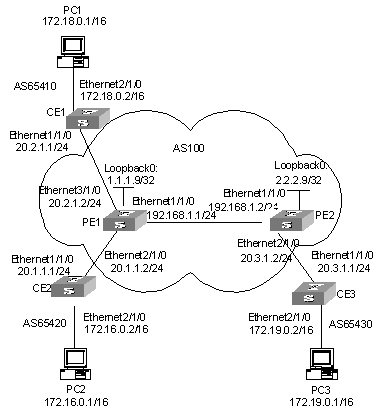
Figure 3-18 Network diagram for multi-role host application
III. Configuration procedure
1) Configure OSPF as the IGP protocol on the MPLS backbone network.
# Configure OSPF on PE1:
[PE1] interface loopback 0
[PE1-LoopBack0] ip address 1.1.1.9 32
[PE1-LoopBack0] quit
[PE1] vlan 110
[PE1-vlan110] interface vlan-interface 110
[PE1-Vlan-interface110] ip address 192.168.1.1 24
[PE1-Vlan-interface110] quit
[PE1] ospf
[PE1-ospf-1] area 0
[PE1-ospf-1-area-0.0.0.0] network 192.168.1.0 0.0.0.255
[PE1-ospf-1-area-0.0.0.0] network 1.1.1.9 0.0.0.0
[PE1-ospf-1-area-0.0.0.0] quit
[PE1-ospf-1] quit
# Configure OSPF on PE2:
[PE2] interface loopback 0
[PE2-LoopBack0] ip address 2.2.2.9 32
[PE2-LoopBack0] quit
[PE2] vlan 110
[PE2-vlan110] interface vlan-interface 110
[PE1-Vlan-interface110] ip address 192.168.1.2 24
[PE2-Vlan-interface110] quit
[PE2] ospf
[PE2-ospf-1] area 0
[PE2-ospf-1-area-0.0.0.0] network 192.168.1.0 0.0.0.255
[PE2-ospf-1-area-0.0.0.0] network 2.2.2.9 0.0.0.0
[PE2-ospf-1-area-0.0.0.0] quit
[PE2-ospf-1] quit
2) Configure basic MPLS capability and create VPN instances.
# Configure basic MPLS capability on PE1:
[PE1] mpls lsr-id 1.1.1.9
[PE1-mpls] lsp-trigger all
[PE1-mpls] quit
[PE1] mpls ldp
[PE1-mpls-ldp] quit
[PE1] vlan 110
[PE1-vlan110] interface vlan-interface 110
[PE1-Vlan-interface110] mpls
[PE1-Vlan-interface110] mpls ldp
[PE1-Vlan-interface110] quit
# Create VPN instances for VPN1 and VPN2 on PE1, bind the address of the interface of VLAN310 to VPN1 and VPN2.
[PE1] ip vpn-instance vpn1
[PE1-vpn-vpn1] route-distinguisher 100:1
[PE1-vpn-vpn1] vpn-target 100:1 both
[PE1-vpn-vpn1] quit
[PE1] ip vpn-instance vpn2
[PE1-vpn-vpn2] route-distinguisher 100:2
[PE1-vpn-vpn2] vpn-target 100:2 both
[PE1-vpn-vpn2] quit
[PE1] vlan 310
[PE1-vlan310] interface vlan-interface 310
[PE1-Vlan-interface310] ip binding vpn-instance vpn1
[PE1-Vlan-interface310] ip address 20.2.1.2 24
[PE1-Vlan-interface310] quit
[PE1] vlan 210
[PE1-vlan210] interface vlan-interface 210
[PE1-Vlan-interface210] ip binding vpn-instance vpn2
[PE1-Vlan-interface210] ip address 20.1.1.2 24
[PE1-Vlan-interface210] quit
# Configure basic MPLS capability on PE2.
[PE2] mpls lsr-id 2.2.2.9
[PE2-mpls] lsp-trigger all
[PE2-mpls] quit
[PE2] mpls ldp
[PE2-mpls-ldp] quit
[PE2] vlan 110
[PE2-vlan110] interface vlan-interface 110
[PE2-Vlan-interface110] mpls
[PE2-Vlan-interface110] mpls ldp
[PE2-Vlan-interface110] quit
# Create a VPN instance for VPN1 on PE2, and bind the address of the interface of VLAN210 to VPN1.
[PE2] ip vpn-instance vpn1
[PE2-vpn-vpn1] route-distinguisher 300:1
[PE2-vpn-vpn1] vpn-target 100:1 both
[PE2-vpn-vpn1] quit
[PE2] vlan 210
[PE2-vlan210] interface vlan-interface 210
[PE2-Vlan-interface210] ip binding vpn-instance vpn1
[PE2-Vlan-interface210] ip address 20.3.1.2 24
[PE2-Vlan-interface210] quit
Configure BGP.
# Configure CE1:
[CE1] vlan 310
[CE1-vlan310] interface vlan-interface 310
[CE1-Vlan-interface310] ip address 20.2.1.1 24
[CE1-Vlan-interface310] quit
[CE1] bgp 65410
[CE1-bgp] import-route direct
[CE1-bgp] group 10 external
[CE1-bgp] peer 20.2.1.2 group 10 as-number 100
[CE1-bgp] quit
# Configure CE2:
[CE2] vlan 210
[CE2-vlan210] interface vlan-interface 210
[CE2-Vlan-interface210] ip address 20.1.1.1 24
[CE2-Vlan-interface210] quit
# Configure CE3:
[CE3] vlan 210
[CE3-vlan210] interface vlan-interface 210
[CE3-Vlan-interface210] ip address 20.3.1.1 24
[CE3-Vlan-interface210] quit
[CE3] bgp 65430
[CE3-bgp] import-route direct
[CE3-bgp] group 10 external
[CE3-bgp] peer 20.3.1.2 group 10 as-number 100
[CE3-bgp] quit
# Configure PE1: Configure PE1 to be the IBGP peer of PE2 in BGP-VPNv4 sub-address family view. Configure PE1 to be the EBGP peer of CE1 in the BGP VPN1 instance view. Configure a static route between CE2 and PE1 to enable them to communicate with each other. Import a static route in BGP VPN2 instance view to advertise it to the remote PE.
[PE1] bgp 100
[PE1-bgp] group 10
[PE1-bgp] peer 2.2.2.9 group 10
[PE1-bgp] peer 2.2.2.9 connect-interface loopback 0
[PE1-bgp] ipv4-family vpnv4
[PE1-bgp-af-vpn] peer 10 enable
[PE1-bgp-af-vpn] peer 2.2.2.9 group 10
[PE1-bgp-af-vpn] quit
[PE1-bgp] ipv4-family vpn-instance vpn1
[PE1-bgp-af-vpn-instance] import-route direct
[PE1-bgp-af-vpn-instance] group 20 external
[PE1-bgp-af-vpn-instance] peer 20.2.1.1 group 20 as-number 65410
[PE1-bgp-af-vpn-instance] quit
[PE1-bgp] ipv4-family vpn-instance vpn2
[PE1-bgp-af-vpn-instance] import-route direct
[PE1-bgp-af-vpn-instance] import-route static
# Configure PE2: set up IBGP peer relation with PE1 in BGP-VPNv4 sub-address family view; set up EBGP peer relation with CE3 in BGP-VPN instance view.
[PE2] bgp 100
[PE2-bgp] group 10
[PE2-bgp] peer 1.1.1.9 group 10
[PE2-bgp] peer 1.1.1.9 connect-interface loopback 0
[PE2-bgp] ipv4-family vpnv4
[PE2-bgp-af-vpn] peer 10 enable
[PE2-bgp-af-vpn] peer 1.1.1.9 group 10
[PE2-bgp-af-vpn] quit
[PE2-bgp] ipv4-family vpn-instance vpn1
[PE2-bgp-af-vpn-instance] import-route direct
[PE2-bgp-af-vpn-instance] group 20 external
[PE2-bgp-af-vpn-instance] peer 20.3.1.1 group 20 as-number 65430
[PE2-bgp-af-vpn-instance] quit
[PE2-bgp] quit
Configure multi-role host feature: If a routing protocol is employed between CE2 and PE1, configure PE1 not to advertise any route information to CE2 to avoid route loops. Following depicts a way to achieve this. You can also avoid route loops in other ways. Directly configure a static route to PC2 on PE1 if no routing protocol is employed between PE1 and CE2.
# Configure a default route pointing to PE1 on CE2.
[CE2] ip route-static 0.0.0.0 0.0.0.0 20.1.1.2
# Configure a multiple-role host route on PE1.
[PE1] ip route-static vpn-instance vpn1 172.16.0.0 16 vpn2 20.1.1.1
# Import the route of VPN1 to VPN2 using the RT attribute.
[PE1] ip vpn-instance vpn2
[PE1-vpn-vpn2] vpn-target 100:1 import-extcommunity
3.5 Troubleshooting
I. Symptom 1
In central server topology networking mode, the local end switch (spoke PE) cannot learn the routing information of the peer end switch (spoke PE).
Solution:
l Check whether the BGP adjacent of spoke PE and hub PE is created correctly.
l Check whether the routing attributes import/export relation of each VPN-instance is correct.
l Check from the hub PE that whether the routing information between two VPN instances can be learnt by each other. if not, perform the following operation: check if the EBGP protocol runs between hub PE and hub CE, check whether the peer peer-address allow-as-loop command is configured between PE and CE.
II. Symptom 2
PE at the local end can learn private network route of the PE at peer end, but two PEs cannot intercommunicate with each other.
Solution:
l Check whether the loopback interface configured on the PE has the address with 32-bit mask.
l Check whether the tag of private network route is correct.
l Check whether the LDP session is established using the display mpls ldp session command.
l Check whether the LSP tunnel is established using the display mpls lsp command.
III. Symptom 3
In Hub&Spoke networking mode, spoke PE cannot learn the private networking route of Hub PE.
Solution:
l Check whether the LSP tunnel is established using the display mpls lsp command.
l Check whether the BGP adjacent is established correctly.
l Check whether the routing import/export relation of the VPN-instance is correct.
l Check whether allow-as-loop is configured between spoke PE and hub PE.
IV. Symptom 4
Fall to specify the Loopback interface at the peer end as the BGP neighbor.
Solution:
l Check whether the local routing table has learnt the Loopback interface routing information of the peer end using the display ip routing-table command.
l Check whether the address of the Loopback interface at the peer end can be pinged using the ping command.
l Check whether the configuration information is correct using the display current-configuration bgp command; confirm that you have specified the local loopback interface as the interface to create adjacent interface with the peer end by using the peer peer-address connect-interface command; confirm that you have activate the neighbor in VPNv4 sub-address family view.
l Check whether the BGP information is correct on the PE at the peer end; check whether specified the local Loopback interface as the interface to create adjacent with the peer end; and check whether you have configured VPN capacity.
V. Symptom 5
During ASBR configuration, VPN route interior label does not switch on the ASBR.
Solution:
l Check whether the VPN neighbor is created correctly using the display bgp vpnv4 all peer command.
l Check whether ASBR is configured with the undo policy vpn-target command. If not, configure this command.
Chapter 4 MPLS L2VPN
& Note:
L2VPN mentioned in the following section refers to the L2VPN implemented through virtual leased line (VLL).
4.1 MPLS L2VP Overview
4.1.1 Introduction to MPLS L2VP
MPLS L2VPN provides MPLS network-based Layer 2 VPN services. For users, an MPLS L2VPN is a Layer 2 switched network, through which Layer 2 connections can be established between network nodes.
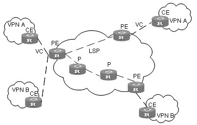
MPLS L2VPN has the following advantages:
l Multiple network layer protocols supported, such as IP, IPv6, IPX, and SNA.
l Powerfulextensibility. MPLS L2VPN only establishes Layer 2 connections, rather than imports and manages the routing information. This eases work load of PE (provider edge) devices and the entire SP (service provider) network remarkably and thus enables SPs to provide more VPNs and accommodate more users.
l Reliability and privacy of user routes. As no user routing information is imported, there is no need for MPLS L2VPN to obtain and process the information, ensuring the privacy of user routes.
Figure 4-2 illustrates the structure of an MPLS L2VPN packet.
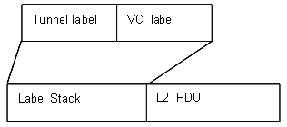
Figure 4-2 Structure of an MPLS L2VPN packet
The fields in an MPLS L2VPN packet are described as follows:
Tunnel label (the outer label) is an MPLS label or a GRE label. It is used to transmit a packet from one PE to anther.
VC label (the inner label) is a lower layer label used to identify the links between PEs and CEs. Packets of MPLS L2VPNs implemented through circuit cross connect (CCC) do not contain this label.
Data in MPLS L2VPN can be encapsulated as Ethernet or VLAN packets at the data link layer. At present, data of different nodes in a VPN must be encapsulated as the same type of packets.
4.1.2 Packet Forwarding
In an MPLS L2VPN, CE, PE, and P operate in the same way as those in a BGP/MPLS VPN. That is, they also forward packets in an MPLS network transparently by using label stacks. To forward packets in an MPLS L2VPN, tunnels must be established first between PEs (this can be achieved by either manual configuration or signaling protocols). When the interfaces connecting PEs and CEs are up, PEs insert VC labels for packets sent by CE, and then mark them with tunnel labels. On receiving these packets, the remote PEs strip off the tunnel labels and send the packets to the corresponding CEs according to their VC labels.
Table 4-3 illustrates changes of the label stack of a packet during the forwarding.
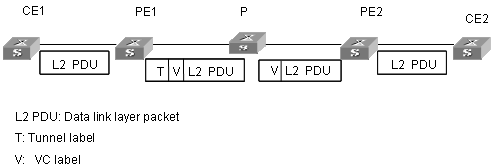
Figure 4-3 Label stack processing of MPLS L2VPN
4.1.3 Implementation
At present, the official standard for MPLS L2VPN has not been established yet. However, the PPVPN (Provider-provisioned Virtual Private Network) group of IETF (Internet Engineering Task Force) defines multiple framework drafts, two of which are commonly used. They are known as Martini draft and Kompella draft. Till May, 2005, they are depicted in the following documents respectively:
draft-martini-l2circuit-trans-mpls-09.txt
draft-kompella-ppvpn-l2vpn-02.txt
Martini draft defines the way to implement MPLS L2VPN by establishing point-to-point links. Here, LDP (Label Distribution Protocol) is used as the signaling protocol to exchange VC labels. This kind of MPLS L2VPNs is known as Martini MPLS L2VPNs.
Kompella draft defines how to establish MPLS L2VPNs in MPLS networks through end-to-end (CE-to-CE) connections. At present, BGP (border gateway protocol) is used as the signaling protocol to propagate the information about Layer 2 reachability and VC labels. This kind of MPLS L2VPNs is known as Kompella MPLS L2VPN.
Also, you can establish MPLS L2VPNs without signaling protocols. In this case, MPLS L2VPN services are provided through statically configured VC labels. An example of this is CCC, which implement MPLS L2VPNs through static configuration.
Table 4-1 describes the features and implementation ways of the above three types of MPLS L2VPNs.
Table 4-1 Features and implementation ways of the three types of MPLS L2VPNs
|
VPN type |
Implementation |
Feature |
|
CCC |
Configures static LSPs to implement MPLS L2VPN. You must manually configure two LSPs (for sending and receiving packets respectively) for each CCC connection node by node (including PEs and Ps). The configured LSPs can only be used to transmit packets of the corresponding CCC connections. |
Data is transmitted through packets with single-layer labels. LSPs are used exclusively. No signaling is needed to transmit the Layer 2 VPN information. Only MPLS forwarding is required. In this way, CEs of different SPs can be interconnected easily. |
|
Martini |
Uses extended LDP as the signaling to transmit the VC information. Uses VC-TYPE and VC-ID to identify VCs. VC-TYPE indicates the encapsulation type of data link layer, and VC-ID uniquely identifies a VC. PEs connecting CEs exchange VC labels through LDPs. They bind the corresponding CEs through VC-IDs. |
Local switching like CCC is not available. An LSP can be shared by multiple VCs. |
|
Kompella |
Similar to Layer 3 BGP/MPLS VPN defined in RFC2547. PEs discover Layer 2 VPN nodes automatically through IBGP sessions established between them. They also propagate the VPN information. Labels are distributed in the form of label blocks, which enables multiple connections being assigned tags simultaneously. The size of a tag block is determined by CE Range (user-configurable). VPN-target is used to differentiate VPNs. |
Users can assign extra labels to VPNs for future use. This eases the configuration work loads of VPN deployment and capacity expansion. VPN-target is used to identify VPNs. This brings great flexibility for VPN networking. Connections between CEs are not concerned. This type of MPLS L2VPN is implemented by dividing the entrie SP network into different VPNs and numbering these CEs in the VPNs. To establish a connection between two CEs, you need to set the local CE ID and the remote CE ID on the PE, and specify the Circuit ID assigned for the connection by the local CE. |
& Note:
You also can configure LSPs without P devices.
4.2 CCC MPLS L2VPN Configuration
4.2.1 Configuring CCC MPLS L2VPN
Table 4-2 Configure CCC MPLS L2VPN
|
Configuration step |
Command |
Description |
|
Enter system view |
system-view |
- |
|
Configure LASR ID |
mpls lsr-id X.X.X.X |
Required |
|
Enable MPLS |
mpls |
Required |
|
Create the egress for the static LSP |
static-lsp egress lsp-name l2vpn incoming-interface vlan-interface vlan-id in-label in-label |
Required. Before configuring a CCC connection, you need to configure two static LSPs between the two PEs and all P routers in between for bidirectional packets. Refer to corresponding sections in the command manual for more information about these commands and corresponding undo commands. |
|
Create the ingress for the static LSP |
static-lsp ingress lsp-name l2vpn nexthop next-hop-addr out-label out-label |
|
|
Create the transit for the static LSP |
static-lsp transit lsp-name l2vpn incoming-interface vlan-interface vlan-id in-label in-label { nexthop next-hop-addr | outgoing-interface vlan-interface vlan-id } out-label out-label |
|
|
Quit MPLS view and enter system view |
quit |
- |
|
Enable MPLS L2VPN |
mpls l2vpn |
Required |
|
Establish local CCC connection |
ccc ccc-connection-name interface vlan-interface vlan-id out-interface |
Required. Two types of CCC connections exist: local CCC connection and remote CCC connection. A local CCC connection is established between two local CEs. It can be switched directly by the PE without being configured a static LSP. A remote CCC connection is established between the local CE and a remote CE. The two CEs are attached to different PEs. In this case, you need to configure two static LSPs for bidirectional packets transmitted between the two PEs. |
|
Establish remote CCC connection |
ccc ccc-connection-name interface vlan-interface vlan-id transmit-lsp transmit-lsp-name receive-lsp receive-lsp-name |
![]() Caution:
Caution:
l In L2VPN, you can configure only one virtual circuit for each VLAN interface.
l L2VPN supports VLAN interfaces only. When you configure an L2VPN on a VLAN interface, data is encapsulated as Ethernet packets by default.
l You must use cards with the suffix CA (such as LSB2FT48CA) for the access sides of CCC public/private network.
l You can configure only one VLAN on the access side of each VPN private network. Each VLAN can have only one interface, and all the VLANs connecting to the interface must have IGMP disabled.
l You must configure two static LSPs for each remote CCC connection. Two CCC connections cannot share one static LSP.
l A static LSP used by a remote CCC connection cannot be used for other purposes (such as carrying IP packets and BGP/MPLS VPN packets). When you configure a static LSP for a CCC connection, the next hop must be the IP address from which the ARP packets are learnt.
4.2.2 CCC MPLS L2VPN Configuration Example
I. Network requirements
CEs and the corresponding PEs shown in Figure 4-4 are interconnected through their GigabitEthernet ports. Data is encapsulated as Ethernet packets at the data link layer. A local connection is required between CE-A and CE-B, and a remote connection between CE-A and CE-C.
II. Network diagram
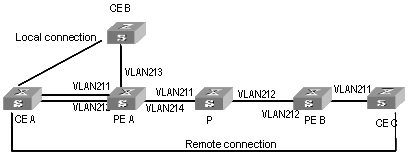
Figure 4-4 Network diagram for CCC MPLS L2VPN
III. Configuration procedure
1) Configure PE-A.
# Enable MPLS globally.
[H3C] mpls lsr-id 1.1.1.1
[H3C] mpls
# Enable MPLS L2VPN globally.
[H3C] mpls l2vpn
# Configure VLAN 211.
[H3C] vlan 211
[H3C-vlan211] port gigabitethernet 2/1/1
[H3C-Vlan211] interface vlan-interface 211
[H3C-Vlan-interface211] quit
# Configure VLAN 212.
[H3C] vlan 212
[H3C-vlan212] port gigabitethernet 2/1/2
[H3C-vlan212] interface vlan-interface 212
[H3C-Vlan-interface212] quit
# Configure VLAN 213.
[H3C] vlan 213
[H3C-vlan213] port gigabitethernet 2/1/3
[H3C-vlan213] interface vlan-interface 213
[H3C-Vlan-interface213] quit
# Enable MPLS on the interface of VLAN 214.
[H3C] vlan 214
[H3C-vlan214] port gigabitethernet 2/1/4
[H3C-vlan214] quit
[H3C] interface vlan-interface 214
[H3C-Vlan-interface214] ip address 5.5.5.1 24
[H3C-Vlan-interface214] mpls
[H3C-Vlan-interface214] quit
# Configure the local connection.
[H3C] ccc local-conn interface vlan-interface 211 outgoing-interface vlan-interface 213
# Configure a static LSP, with the out-label of 100 and the egress interface being the interface of VLAN 214.
[H3C] mpls
[H3C-mpls] static-lsp ingress PEA-PEB l2vpn nexthop 5.5.5.2 out-label 100
# Configure a static LSP, with the in-label of 211 and the ingress interface being the interface of VLAN 214.
[H3C-mpls] static-lsp egress PEB-PEA l2vpn incoming-interface vlan-interface 214 in-label 211
# Configure the remote connection.
[H3C] ccc remote-connection interface vlan-interface 212 transmit-lsp PEA-PEB receive-lsp PEB-PEA
2) Configure PE-B.
# Enable MPLS globally.
[H3C] mpls lsr-id 10.0.0.1
[H3C] mpls
# Enable MPLS L2VPN globally.
[H3C] mpls l2vpn
# Configure VLAN 211.
[H3C] vlan 211
[H3C-vlan211] port gigabitethernet 2/1/1
[H3C] interface vlan-interface 211
[H3C-Vlan-interface211] quit
# Enable MPLS on the interface of VLAN 212.
[H3C] vlan 212
[H3C-vlan212] port gigabitethernet 2/1/2
[H3C-vlan212] quit
[H3C] interface Vlan-interface 212
[H3C-Vlan-interface212] ip address 6.6.6.1 24
[H3C-Vlan-interface212] mpls
# Configure a static LSP, with the out-label of 200 and the egress interface being the interface of VLAN 212.
[H3C-mpls] static-lsp ingress nexthop 6.6.6.2 out-label 200
# Configure a static LSP, with the in-label of 101 and the ingress interface being the interface of VLAN 212.
[H3C-mpls] static-lsp egress PEA-PEB l2vpn incoming-interface vlan-interface 212 in-label 101
# Configure the remote connection.
[H3C] ccc remote-connection interface vlan-interface 211 transmit-lsp PEB-PEA receive-lsp PEA-PEB
3) Configure P.
[H3C] mpls lsr-id 10.0.0.2
[H3C] mpls
[H3C] vlan 211
[H3C-vlan211] port gigabitethernet 2/1/1
[H3C-vlan211] quit
[H3C] interface Vlan-interface 211
[H3C-Vlan-interface211] ip address 5.5.5.2 24
[H3C-Vlan-interface211] mpls
[H3C] vlan 212
[H3C-vlan212] port gigabitethernet 2/1/2
[H3C-vlan212] quit
[H3C] interface Vlan-interface 212
[H3C-Vlan-interface212] ip address 6.6.6.2 24
[H3C-Vlan-interface212] mpls
# Configure a static LSP, with the in-label of 100, the ingress interface being the interface of VLAN 211, the out-label of 101, and the egress interface being the interface of VLAN 212.
[H3C-mpls] static-lsp transit PEA-PEB l2vpn incoming-interface vlan-interface 211 in-label 100 nexthop 6.6.6.1 vlan-interface 212 out-label 101
# Configure a static LSP, with the in-label of 200, the ingress interface being the interface of VLAN 212, the out-label of 211, and the egress interface being the interface of VLAN 211.
[H3C-mpls] static-lsp transit PEB-PEA l2vpn incoming-interface vlan-interface 212 in-label 200 nexthop 5.5.5.1 out-label 211
![]() Caution:
Caution:
Following must be met to make a local CCC connection to go up:
l The interfaces of the two CE are physically up.
l The encapsulation types of the interfaces of the two CEs are the same and are supported by the MPLS L2VPN.
For Layer 2 connections with the MPLS L2VPN being VLAN encapsulation, the VLAN IDs of the interfaces of the two CEs can either be the same or different. However, if a trunk is configured between the CEs and the PEs on both sides, the VLAN IDs of the interfaces of the two CEs must be the same.
4.3 Martini MPLS L2VPN Configuration
4.3.1 Configuring Martini MPLS L2VPN
Table 4-3 Configure Martini MPLS L2VPN
|
Configuration step |
Command |
Description |
|
Enter system view |
system-view |
- |
|
Configure the LSR ID |
mpls lsr-id X.X.X.X |
Required |
|
Enable MPLS |
mpls |
Required |
|
Quit to system view |
quit |
- |
|
Configure the LDP remote peer |
mpls ldp remote-peer index |
Required. Before configuring the connection, you need to enable LDP on each router and each port of the public network along the connection and configure the LDP remote peer on the peer PE. Refer to LDP Configuration in MPLS module for the configuration related to LDP . |
|
Quit to system view |
quit |
- |
|
Enter VLAN interface view |
interface vlan-interface vlan id |
- |
|
Enable MPLS L2VPN |
mpls l2vpn |
Required |
|
Create a Martini MPLS L2VPN virtual connection in VLAN interface view |
mpls l2vc ip-address vc-id |
Required. To configure a Martini MPLS L2VPN on a PE, you need to provide the IP address (Lsr-id) of the peer PE and specify the VC ID. The combination of the VC ID and the encapsulation type must be unique on the PE. |
|
Quit to system view |
quit |
- |
l You must use cards with the suffix CA (such as LSB2FT48CA) on the public/private network access sides when configuring Martini MPLS L2VPN.
l You can configure only one VLAN on the access side of each VPN private network. Each VLAN can have only one interface. And all the VLANs connecting to the interface must have IGMP disabled.
l L2VPN supports VLAN interfaces only. When you configure an L2VPN on a VLAN interface, data is encapsulated as Ethernet packets by default.
4.3.2 Martini MPLS L2VPN Configuration Example
I. Network requirements
CEs shown in Figure 4-5 are in the same VLAN as the corresponding PEs resides in. A remote connection is required between CE-A and CE-B.
II. Network diagram
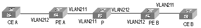
Figure 4-5 Network diagram for Martini MPLS L2VPN
III. Configuration procedure
1) Configure PE-A.
# Configure the LSR ID. Enable MPLS, LDP, and MPLS L2VPN.
[H3C-A] mpls lsr-id 192.1.1.1
[H3C-A] mpls
[H3C-A-mpls] quit
[H3C-A] mpls ldp
[H3C-A] mpls l2vpn
# Configure VLAN 212.
[H3C-A] vlan 212
[H3C-A-vlan212] port gigabitethernet 2/1/2
[H3C-A-vlan212]interface vlan-interface 212
[H3C-Vlan-interface212] quit
# Configure the VLAN interface.
[H3C-A] vlan 211
[H3C-A-vlan211] port gigabitethernet 2/1/1
[H3C-A-vlan211] quit
[H3C-A] interface Vlan-interface 211
[H3C-A-Vlan-interface211] ip address 168.1.1.1 255.255.0.0
[H3C-A-Vlan-interface211] mpls
[H3C-A-Vlan-interface211] mpls ldp enable
# Configure an IP address for the Loopback interface, which is used as the Router ID.
[H3C-A] interface loopback 0
[H3C-A-LoopBack0] ip address 192.1.1.1 255.255.255.255
# Enable OSPF.
[H3C-A] ospf 1
[H3C-A-ospf-1] area 0.0.0.0
[H3C-A-ospf-1-area-0.0.0.0] network 192.1.1.1 0.0.0.0
[H3C-A-ospf-1-area-0.0.0.0] network 168.1.1.1 0.0.255.255
# Create an LSP tunnel.
[H3C-A] mpls ldp
# Configure the LDP Remote Peer.
[H3C-A] mpls ldp remote-peer 1
[H3C-A-remote-peer-1] remote-ip 192.1.1.2
# Configure a Martini MPLS L2VPN connection.
[H3C-A] interface vlan-interface 212
[H3C-A-Vlan-interface212] mpls l2vc 192.1.1.2 20
2) Configure PE-B.
# Configure the LSR ID. Enable MPLS, LDP, and MPLS L2VPN.
[H3C-B] mpls lsr-id 192.1.1.2
[H3C-B] mpls
[H3C-B-mpls] quit
[H3C-B] mpls ldp
[H3C-B] mpls l2vpn
# Configure VLAN 211.
[H3C-B] vlan 211
[H3C-B-vlan211] port gigabitethernet 2/1/1
[H3C-B-vlan211] interface Vlan-interface 211
[H3C-Vlan-interface 211] quit
# Configure the VLAN interface.
[H3C-B] vlan 212
[H3C-B-vlan212] port gigabitethernet 2/1/2
[H3C-B-vlan212] quit
[H3C-B] interface Vlan-interface 212
[H3C-B-Vlan-interface212] ip address 169.1.1.1 255.255.0.0
[H3C-B-Vlan-interface212] mpls
[H3C-B-Vlan-interface212] mpls ldp enable
# Configure an IP address for the Loopback interface, which is used as the LSR ID.
[H3C-B] interface loopback 0
[H3C-B-LoopBack0] ip address 192.1.1.2 255.255.255.255
# Enable OSPF.
[H3C-B] ospf 1
[H3C-B-ospf-1] area 0.0.0.0
[H3C-B-ospf-1-area-0.0.0.0] network 192.1.1.2 0.0.0.0
[H3C-B-ospf-1-area-0.0.0.0] network 169.1.0.0 0.0.255.255
[H3C-B-ospf-1-area-0.0.0.0] network 192.2.0.0 0.0.0.255
# Create an LSP tunnel.
[H3C-B] mpls
[H3C-B-mpls] mpls ldp
# Configure the LDP Remote Peer.
[H3C-B] mpls ldp remote-peer 1
[H3C-B-mpls-remote1] remote-ip 192.1.1.1
# Configure a Martini MPLS L2VPN connection.
[H3C-B] interface vlan-interface 211
[H3C-B-Vlan-interface211] mpls l2vc 192.1.1.1 20
3) Configure P.
# Configure the LSR ID. Enable MPLS, LDP, and MPLS L2VPN.
[H3C-P] mpls lsr-id 192.1.1.3
[H3C-P] mpls
[H3C-P-mpls] quit
[H3C-P] mpls ldp
[H3C-P] mpls l2vpn
# Configure an IP address for the Loopback interface, which is used as the LSR ID.
[H3C-P] interface loopback 0
[H3C-P-LoopBack0] ip address 192.1.1.3 255.255.255.255
[H3C-P-LoopBack0] quit
# Configure the VLAN interface.
[H3C-P] vlan 211
[H3C-P-vlan211] port gigabitethernet 2/1/1
[H3C-P-vlan211] quit
[H3C-P] interface Vlan-interface 211
[H3C-P-Vlan-interface211] mpls
[H3C-P-Vlan-interface211] mpls ldp enable
[H3C-P-Vlan-interface211] ip address 168.1.1.2 255.255.0.0
[H3C-P-Vlan-interface211] quit
[H3C-P] vlan 212
[H3C-P-vlan212 port gigabitethernet 2/1/2
[H3C-P-vlan212] quit
[H3C-P] interface Vlan-interface 212
[H3C-P-Vlan-interface212] mpls
[H3C-P-Vlan-interface212] mpls ldp enable
[H3C-P-Vlan-interface212] ip address 169.1.1.2 255.255.0.0
# Enable OSPF.
[H3C-P] ospf 1
[H3C-P-ospf-1] area 0.0.0.0
[H3C-P-ospf-1-area-0.0.0.0] network 168.1.0.0 0.0.255.255
[H3C-P-ospf-1-area-0.0.0.0] network 169.1.0.0 0.0.255.255
[H3C-P-ospf-1-area-0.0.0.0] network 192.1.1.3 0.0.0.0
![]() Caution:
Caution:
Following must be met to make an LDP Layer 2 VPN to go up:
l The interfaces of the two CE are physically up.
l Two LSP tunnels, which are opposite in direction, exist between two PEs.
l The encapsulation types of interfaces of the two CEs are the same and are supported by the MPLS L2VPN.
l LDP remote sessions exist between PEs and are in Operational state.
To establish a tunnel, routes to the peer PE are necessary. So you need to configure IGP (interior gateway protocol) on each router along the path, such as OSPF.
4.4 Kompella MPLS L2VPN Configuration
4.4.1 Configuring Kompella MPLS L2VPN
Table 4-4 Configure Kompella MPLS L2VPN
|
Configuration step |
Command |
Description |
|
Enter system view |
system-view |
- |
|
Configure the LSR ID |
mpls lsr-id X.X.X.X |
Required |
|
Enable MPLS |
mpls |
Required |
|
Perform BGP (border gateway protocol) related configuration. Make sure BGP operates properly and routers can discover routes to other routers. |
Refer to BGP Configuration in Routing Protocol module. |
Required. In a Kompella MPLS L2VPN, the extended BGP is used as the signaling protocol to distribute VC labels. So, you also need to configure BGP parameters on PEs. As for the MPLS L2VPN itself, it has no special requirements on the BGP configuration. |
|
Enter L2VPN address family view. |
l2vpn-family |
Required |
|
Activate the peer or peergroup. |
peer { group-name | peer-address } enable |
Required. By default, only the peers of BGP IPv4 unicast address families are active. The peer groups of other types are deactivated and thus cannot exchange the routing information. |
|
Quit to system view |
quit |
- |
|
Create a VPN and specify the encapsulation type. |
mpls l2vpn vpn-name [ encapsulation { ethernet | vlan } ] |
Required. The default encapsulation type is Ethernet. In the Kompella mode, the encapsulation type of the access side of the private network can be Ethernet access and VLAN access. Ethernet access is the default type. If you configure the encapsulation type as Ethernet access, the port link type in a private network VLAN is Access type; if you configure the encapsulation type as VLAN access, the port link type in a private network VLAN is Trunk type. It is not recommended to use Hybrid type as the port link type in a private network VLAN. The user access modes of the instance in all the peer PEs must be consistent. |
|
Configure the RD (route distinguisher) of the MPLS L2VPN |
route-distinguisher route-distinguisher |
Required. For an MPLS L2VPN, you must configure the RD before performing other configurations. An RD cannot be modified once it is configured. The only way to modify a configured RD is to remove the corresponding MPLS L2VPN and create another one. As for L2VPN, it is recommended that you assign a unique RD for each VPN. |
|
Configure the VPN-target of the MPLS L2VPN |
vpn-target vpn-target-ext-community [ import-extcommunity| export-extcommunity | both ] |
Required |
|
Configure the Layer 2 MTU (maximum transmission unit) of the VPN |
mtu mtu |
Optional. The same MTU value must be configured for all PEs in the same VPN. |
|
Create a CE or modify the CE Range of an existing CE |
ce name id id [ range range ] [ default-offset offset ] |
Required. Each CE created on a PE needs to uniquely correspond to one actual CE device connected to the PE. You need to specify a unique ID for these CEs. You can also specify the CE Range. It is desired that the CE ID begins with 1 and increases in step of 1. |
|
Enter an existing CE |
ce name |
|
|
Create connections between CEs |
connection [ ce-offset offset ] { interface vlan-interface vlan-id } |
Required. When planning a VPN, you can specify CE IDs for CEs beginning with 1 and increasing in step of 1, and then establish connections by CE IDs. You can establish connections with CE Offset not provided for simplifying the configuration. In this case, the default CE Offset is used. |
![]() Caution:
Caution:
l You can only change the CE range to a number larger than the existing one. For example, you can change a CE range from 10 to 20, rather than from 10 to 5. The only way to change a CE range to a smaller number is to remove the CE and create a new one.
l You must use cards with suffix CA (such as LSB2FT48CA) on the public/private network access side when configuring Kompella MPLS L2VPN.
l You can configure only one VLAN on the access side of each VPN private network. Each VLAN can have only one interface. And all the VLANs connecting to the interface must have IGMP disabled.
l In Kompella MPLS L2VPN, the encapsulation type on the access side of each private network can be Ethernet access and VLAN access. Ethernet access is the default type. If you configure the encapsulation type as Ethernet access, the port link type in a private network VLAN is Access type; if you configure the encapsulation type as VLAN access, the port link type in a private network VLAN is Trunk type. It is not recommended to use Hybrid type as the port link type in a private network VLAN. The user access modes of the instance in all the peer PEs must be consistent.
4.4.2 Kompella MPLS L2VPN Configuration Example
I. Network requirements
CEs shown in Figure 4-6 are in the same VLAN as the corresponding PEs resides in. A remote connection is required between CE-A and CE-B.
II. Network diagram
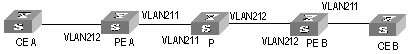
Figure 4-6 Network diagram for Kompella MPLS L2VPN
III. Configuration procedure
1) Configure PE-A.
# Enable MPLS globally.
[H3C] mpls lsr-id 1.1.1.1
[H3C] mpls
# Configure an IP address for the Loopback interface.
[H3C] interface loopback 0
[H3C-LoopBack0] ip address 1.1.1.1 32
# Enable MPLS L2VPN globally.
[H3C] mpls l2vpn
# Configure VLAN 211.
[H3C] vlan 211
[H3C-vlan211] port gigabitethernet 2/1/1
[H3C-Vlan211] interface vlan-interface 211
[H3C-Vlan-interface211] quit
# Configure VLAN 212.
[H3C] vlan 212
[H3C-vlan212] port gigabitethernet 2/1/2
[H3C-vlan212] interface vlan-interface 212
[H3C-Vlan-interface212] quit
# Configure VLAN 213.
[H3C] vlan 213
[H3C-vlan213] port gigabitethernet 2/1/3
[H3C-vlan213] interface vlan-interface 213
[H3C-Vlan-interface 213] quit
# Enable MPLS on the interface of VLAN 214.
[H3C] vlan 214
[H3C-vlan214] port gigabitethernet 2/1/4
[H3C-vlan214] quit
[H3C] interface vlan-interface 214
[H3C-Vlan-interface214] ip address 5.5.5.1 24
[H3C-Vlan-interface214] mpls
[H3C-Vlan-interface214] mpls ldp enable
[H3C-Vlan-interface214] mpls ldp transport-ip interface
[H3C-Vlan-interface214] quit
# Configure BGP.
[H3C] bgp 100
[H3C-bgp] group 100 internal
[H3C-bgp] peer 100 connect-interface loopback0
[H3C-bgp] peer 3.3.3.3 group 100
[H3C-bgp] l2vpn-family
[H3C-bgp-af-l2vpn] peer 100 enable
# Create and configure the VPN.
[H3C] mpls l2vpn vpn1 encapsulation ethernet
[H3C-mpls-l2vpn-vpn1] route-distinguisher 100:1
[H3C-mpls-l2vpn-vpn1] vpn-target 100:1
# Create CE1 and configure the corresponding connection.
[H3C-mpls-l2vpn-vpn1] ce ce1 id 1 range 200
[H3C-mpls-l2vpn-vpn1-ce1] connection ce-offset 2 interface vlan-interface 212
[H3C-mpls-l2vpn-vpn1-ce1] connection ce-offset 3 interface vlan-interface 213
[H3C-mpls-l2vpn-vpn1-ce1] quit
# Enable OSPF.
[H3C] ospf 1 router-id 1.1.1.1
[H3C-ospf-1] area 0.0.0.0
[H3C-ospf-1-area-0.0.0.0] network 1.1.1.1 0.0.0.0
[H3C-ospf-1-area-0.0.0.0] network 5.5.5.0 0.0.0.255
2) Configure PE-B.
# Enable MPLS globally.
[H3C] mpls lsr-id 3.3.3.3
[H3C] mpls
# Configure an IP address for the Loopback interface.
[H3C] interface loopback 0
[H3C-LoopBack0] ip address 3.3.3.3 32
# Enable MPLS L2VPN globally.
[H3C] mpls l2vpn
# Configure VLAN 211.
[H3C] vlan 211
[H3C-vlan211] port gigabitethernet 2/1/1
[H3C-vlan211] quit
# Configure VLAN 212.
[H3C] vlan 212
[H3C-vlan212] port gigabitethernet 2/1/2
[H3C-vlan212] interface vlan-interface 212
[H3C-Vlan-interface 212] quit
# Configure VLAN 213.
[H3C] vlan 213
[H3C-vlan213] port gigabitethernet 2/1/3
[H3C-vlan212] interface vlan-interface 213
[H3C-Vlan-interface 213] quit
# Enable MPLS on the interface of VLAN 214.
[H3C] vlan 214
[H3C-vlan214] port gigabitethernet 2/1/4
[H3C-vlan214] quit
[H3C] interface vlan-interface 214
[H3C-Vlan-interface214] ip address 6.6.6.1 24
[H3C-Vlan-interface214] mpls
[H3C-Vlan-interface214] mpls ldp enable
[H3C-Vlan-interface214] mpls ldp transport-ip interface
[H3C-Vlan-interface214] quit
# Configure BGP.
[H3C] bgp 100
[H3C-bgp] group 100 internal
[H3C-bgp] peer 100 connect-interface loopback0
[H3C-bgp] peer 1.1.1.1 group 100
[H3C-bgp] l2vpn-family
[H3C-bgp-af-l2vpn] peer 100 enable
# Create and configure VPN1.
[H3C] mpls l2vpn vpn1 encapsulation ethernet
[H3C-mpls-l2vpn-vpn1] route-distinguisher 100 :1
[H3C-mpls-l2vpn-vpn1] vpn-target 100 :1
# Create CE2 and configure the corresponding connection.
[H3C-mpls-l2vpn-vpn1] ce ce2 id 2 range 200
[H3C-mpls-l2vpn-vpn1-ce2] connection ce-offset 1 interface vlan-interface 212
[H3C-mpls-l2vpn-vpn1-ce2] quit
[H3C-mpls-l2vpn-vpn1] ce ce3 id 3 range 200
[H3C-mpls-l2vpn-vpn1-ce3] connection ce-offset 1 interface vlan-interface 213
[H3C-mpls-l2vpn-vpn1-ce3] quit
# Enable OSPF.
[H3C] ospf 1 router-id 3.3.3.3
[H3C -ospf-1] area 0.0.0.0
[H3C -ospf-1-area-0.0.0.0] network 3.3.3.3 0.0.0.0
[H3C -ospf-1-area-0.0.0.0] network 6.6.6.0 0.0.0.255
3) Configure the P device.
4.5 Displaying and Debugging MPLS L2VPN
After the above configuration, you can verify your configuration concerning MPLS L2VPN by executing the display command in any view and checking the output information.
You can execute the debugging command in user view to debug MPLS L2VPN.
Table 4-5 Display and debug L2VPN
|
Configuration step |
Command |
Description |
|
Display information about a CCC MPLS L2VPN connection |
display ccc [ ccc-name | type [ local | remote ] ] |
You can execute the display command in any view. |
|
Display information about a Martini MPLS L2VPN connection |
display mpls l2vc [ interface vlan-interface vlan-id | verbose ] |
|
|
Display information about a Kompella MPLS L2VPN connection |
display mpls l2vpn [ vsi-name [ local-ce | remote-ce ] | connection [ vsi-name [ down | remote-ce | up | verbose ] | brief | interface Vlan-interface vlan-id ] | forwarding-info { vc-label | interface interface-type } ] |
|
|
Display information about the system or about Kompella MPLS L2VPNs |
display bgp l2vpn all |
|
|
Enable debugging for MPLS L2VPN |
debugging mpls l2vpn { all | advertisement | error | event | connections [ interface vlan-interface vlan-id ] } |
Execute this command in user view. |
4.6 Troubleshooting MPLS L2VPN
Symptom 1: Fail to configure Layer 2 VPN on the VLAN interface.
Solution:
l Check to see if MPLS/BGP VPN, multicast, or VLL is enabled on the VLAN interface. Because you cannot perform Layer 2 VPN configuration on a VLAN interface if MPLS/BGP VPN, multicasting, or VLL is enabled on it.
l Check to see if the VLAN is a Super-Vlan or a Sub-Vlan. You can perform the Layer 2 VPN configuration only on common VLAN interfaces.
Symptom 2: Fail to ping the peer from one end of a Martini MPLS L2VPN connection. The VC is down and the Remote value is invalid.
Solution:
l VC state being down indicates the encapsulation types or VC IDs of the two ends are not the same. Make sure the interface types (Access or Trunk) of the two PE interfaces and the VC IDs of the two ends are consistent.
l As for the invalid Remote value, make sure you have configured the Remote parameters and the peer addresses correctly.
Symptom 3: Fail to ping the peer of a Kompella MPLS L2VPN connection. The Connection is down and the VPN value is null.
Solution:
l VPN value being null indicates the VPN is configured incorrectly. Make sure the VPN configurations (such as RD) of the both ends are consistent, and the connection configurations of the two CEs on both ends are correct.
l Connection being down indicates configurations concerning encapsulation of the two ends are not the same. Make sure the encapsulation types and MTUs configured for the local and remote PE devices are consistent. A connection fails if the encapsulation types configured on the two ends are not the same.
Symptom 4: Fail to ping the peer end of a CCC MPLS L2VPN connection. The sending and receiving channels are up, so does the linkconnection.
Solution:
l Make sure the in-label and out-label configured on the both ends correspond to each other. If a P device exists, make sure its forwarding connection configuration is correct, and the next hop configured statically is configured.
Chapter 5 Card Intermixing for MPLS Support
5.1 Overview
5.1.1 Introduction to Card Intermixing
For S9500 series routing switches, only the interface cards with suffixes C, CA and CB and VPLS service processor cards support MPLS function. If you want to enable MPLS VPN function of S9500 switches, you need MPLS-supporting interface cards or VPLS service processor cards. The intermixing feature is used to enable deployment of MPLS VPN services on cards that do not support MPLS. S9500 routing switches support various modes of MPLS VPN function and provide abundant and differentiated MPLS VPN service to meet the differentiated needs of different users in the performance, reliability, port utilization of MPLS VPN functions.
& Note:
l Unless otherwise specified, MPLS VPN services are processed by the MPLS-supporting interface cards. In this manual, an interface card that supports MPLS function is called MPLS card for short, and an interface card that does not support MPLS function is called non-MPLS card for short.
l The purpose of card intermixing is to enable the non-MPLS cards to support MPLS function through the MPLS cards. Refer to the “NAT-URPF-VPLS” section in this manual for the information on the processing of MPLS VPN through VPLS service processor cards.
5.1.2 Card Intermixing Mechanism
The implementation mechanism for card intermixing is as follows:
l The MPLS card and the non-MPLS card co-exist in the same switch;
l Use the port of the non-MPLS card for the access to the service private network side of the MPLS VPN ;
l Redirect the port of the non-MPLS card through QACL, to redirect the received packets to the specified MPLS card for processing;
l The port of MPLS card is set as Loopback port automatically and the port type is Trunk;
l The access port of the non-MPLS card and the Loopback port of the MPLS card belong to the same VLAN.
The port on the MPLS card can also be used for the access to the service private network side of the MPLS VPN. In this case, you do not need to configure card intermixing, and you must use the port of the MPLS card for the connection with the MPLS public network side.
& Note:
Because the destination port in intermixing configuration is to be looped back and therefore is locked automatically, you cannot enter the port view. Therefore, you cannot perform other configurations on the destination port.
5.2 Restrictions in Intermixing Networking
5.2.1 Rules of Intermixing Configuration
l A non-MPLS card can be used for access to the private network side, and an MPLS card must be used for access to the public network side;
l You cannot perform other configurations on the destination port in intermixed networking, that is to say, the port view is unavailable. In addition, the destination port in intermixing networking cannot be deleted from the VLAN in the normal way, and the destination port is an inloop port;
l The configured connection status of the source port in intermixing networking is protected. For example, the port type cannot be changed form Trunk to Access or from Access to Trunk, and the source port cannot be deleted from VLAN in the normal way;
l The configuration of the service ports in intermixing networking cannot be changed, and the service ports can be reconfigured only after the intermixing configuration is removed;
l In a VLAN, multiple ports of the non-MPLS card can be redirected to one port of the MPLS card. The destination port of the MPLS card is Looped back automatically (becomes a Loopback port) after it is configured for redirection, and you cannot perform other configurations on the port. Therefore, make sure that the destination port is not in manual Shutdown state before configuring redirection. Only one Loopback port is allowed in the redirected VLAN that the destination port belongs to, but other MPLS card ports are allowed to join in;
l On the Trunk port of a non-MPLS card, you can redirect the MPLS VPNs of multiple VLANs to one destination port to meet the need when the access CE is a Layer 2 switch;
l In non-intermixing networking, VLL application requires that VLANs with only one port be used at the private network side; In intermixing networking, VLL supports only VLANs with two ports: one is the source port (port of the non-MPLS card) and the other is the destination port (port of the MPLS card);
l When the source port (Trunk port) in intermixing networking belongs to multiple VLANs, VPN binding must be implemented on the VLAN interfaces after the redirection configuration;
l If VRRP is configured on the VLAN interface to which the redirected source port of the MPLS VPN belongs, the plugging/unplugging of the MPLS card will cause VRRP group state switching on the VLAN interface.
5.2.2 Restrictions in Card Intermixing
l Source port aggregation and destination port aggregation are not supported;
l Nested VPN is not supported;
l Super VLAN is not supported;
l It is not allowed to change the attributes of the redirected source port;
l It is not allowed to make the redirected source port or destination port to leave redirected VLAN in the normal way;
l It is not allowed to configure protocol VLANs on the redirected source port or destination port;
l It is not allowed to delete the redirected VLAN or VLAN interface;
l It is not allowed to configure/add Loopback ports in the redirected VLAN;
l It is not allowed to use STP edge port as the redirected destination port;
l It is not allowed to change the VLANs and the default VLAN ID which the redirected destination port is permitted to pass;
l If normal ports are used, 4,094 VLL VPNs are supported; if the Trunk port of the card of a fast Ethernet card is used, a maximum of 1024 VLL VPNs are supported;
l Only cards with suffix CA can be used at the public network side for VLL configuration;
l Redirection configuration for MPLS VPN intermixing is not supported on the POS and RPR ports, and the POS port cannot be used as the destination port for MPLS VPN redirection;
A Trunk-type 100M Ethernet port can use only 1024 VLANs for VPN access or MPLS forwarding, but you can specify the start VLAN ID of the 100M Ethernet Trunk port. Assume the start VLAN ID is VLAN ID, the range of VLAN IDs of the VLANs that pass a certain 100M Ethernet port is from VLAN ID to VLAN ID + 1023.
5.3 Introduction to intermixing configuration task
Table 5-1 Introduction to intermixing configuration task
|
Configuration task |
Description |
Detailed configuration |
|
Configuring public network routing protocols |
Required |
Refer to related sections in Routing Protocol Operation |
|
Configure the basic capability of MPLS |
Required |
Refer to Chapter 2 in MPLS Operation |
|
Configuring MPLS VPN |
Required |
Refer to Chapter 3 and Chapter 4 in MPLS Operation |
|
Configuring flow template and ACL rules |
Required |
Refer to 5.3.5 |
|
Applying flow template on the port and configuring redirection |
Required |
Refer to 5.3.5. |
5.3.1 Configuring Routing Protocols
The Switch should be configured with some basic routing configurations so that it can exchange public network routing information with other P devices and PE devices. The routing protocols available currently include: static routing, RIP, OSPF, BGP and so on. Refer to the “Routing Protocols” part of the H3C S9500 Routing Switches Operation Manual I for detailed configuration information.
5.3.2 Configuring Basic Capability of MPLS
Configure MPLS basic capability to enable MPLS and LDP globally and on the public network interface, to establish an LSP tunnel for the public network. Refer to Chapter 2 MPLS Basic Capability Configuration for detailed configuration information.
5.3.3 Configuring MPLS VPN
Configure BGP/MPLS VPN (L3VPN) or L2VPN. Refer to Chapter 3 BGP/MPLS VPN Configuration and Chapter 4 MPLS L2VPN for detailed configuration information.
5.3.4 Configuring flow template and ACL rules
The packets to be redirected are identified through the flow template and ACL configurations.
I. For L2VPN
Table 5-2 Configure the flow template and ACL of L2VPN
|
Operation |
Command |
Description |
|
Enter system view |
system-view |
- |
|
Enter corresponding ACL view |
acl { number acl-number | name acl-name link ] } [ match-order { config | auto } ] |
Required |
|
Configure rules of ACL |
rule [ rule-id ] permit ingress vlan-id |
Required. L2VPN can use either the default flow template or a custom flow template. It is recommended to redirect the packets in the specified VLAN through matching them with a Layer 2 rule so that the specified VLAN packets can pass. |
II. For L3VPN
Table 5-3 Configure flow template and ACL rules of L3VPN
|
Operation |
Command |
Description |
|
Enter system view |
system-view |
- |
|
Set self-defined flow template |
flow-template user-defined slot slotid dmac wildcard sip wildcard vlanid |
Require. When a custom flow template is specified, at least two items IP and DMAC are required. You can use the IP + VLAN + DMAC method to define the flow template so that different kinds of packets are processed in different ways. |
|
Enter corresponding ACL view |
acl { number acl-number | name acl-name [ advanced | basic ] } [ match-order { config | auto } ] |
Required |
|
Configure IP ACL |
rule [ rule-id ] permit source { source-addr wildcard | any } |
Required. You can use the parameter permit any or specify an IP address. |
|
Configure Layer 2 ACL |
rule [ rule-id ] permit ingress vlan-id egress dest-mac-addr dest-mac-wildcard |
Required. Use a Layer 2 rule to configure VLAN+DMAC. DMAC refers to the virtual MAC of the switch. You can get it through the display interface vlan vlanid command. |
You can define the flow template by means of the IP + VLAN + DMAC method to make sure that different kinds of packets are processed in different ways:
l If ARP packets do not match IP rules in redirection, they will be processed on the non-MPLS card;
l If Layer 2 traffic does not match DMAC in redirection, it will be L2-forwarded on the non-MPLS card;
l If Layer 3 packets (including unicast protocol packets) match the rule, they will be redirected to the MPLS card.
Refer to section “QACL” and the following networking example in the manual for detailed information on configuring flow template and ACL rules.
5.3.5 Applying Flow Template and Redirection in Port Mode
Table 5-4 Applying Flow Template and Redirect in Port Mode
|
Operation |
Command |
Description |
|
Enter system view |
system-view |
- |
|
Enter port view |
interface interface-type interface-number |
- |
|
Apply flow template in port mode |
flow-template user-defined |
Required |
|
Configure the traffic-redirect command |
traffic-redirect inbound ip-group { acl-number | acl-name } [ rule rule] link-group [ rule rule ] interface interface-type interface-number destination-vlan { l2-vpn | l3-vpn } slot slotid vlanid [Join-vlan ] } |
Required l3-vpn | l2-vpn means the command is applicable to L2VPN or L3VPN of MPLS. slot slotid vlanid: the slot id of the service card which the VPLS packets are redirected to and the ID of the VLAN to join in. |
The traffic-redirect command is used to enable ACL flow classification and redirect the packets (only applicable to the rules whose action is permit in the ACL). There are two kinds of redirection commands:
l Redirect packets to a port: You can redirect packets received by the source port of the non-MPLS card to the specified destination port of the MPLS card.
l Redirect packets to a service processor card: You can redirect packets received by the source port of the non-MPLS card or MPLS card to the VPLS card.
There are two kinds of redirection services:
l VPLS-related redirection services: The key word join-vlan must be specified, and the system will add the current port into destination-vlan after the redirection enabled; when redirection is disabled, the system will log the current port out of the VLAN if what is deleted is a join-vlan enabled redirection in the VLAN.
l MPLS-independent redirection services: Such redirection services include NAT, URPT, reflexive ACL, BT traffic control and so on. join-vlan cannot be enabled in such a service. The port will not be added into VLAN when redirection is configured, and the port will not be removed from the VLAN when redirection is deleted.
& Note:
l The source port joins in the corresponding VLAN automatically after the configuration of intermixing redirection, and the source port leaves the corresponding VLAN automatically after the intermixing redirection is deleted.
l When using the VPLS intermixing redirection command, you have to enable join-vlan explicitly.
l When using the VLL VPN intermixing redirection command, you must not enable the QinQ function on the source port and destination port.
5.3.6 Typical Networking Example
I. Network requirements
l CE1 and CE3 constitute VPN A, and CE2 and CE4 constitute VPN B. In PE1, a port of an interface card with suffix C is shared, and in PE2, a Layer 2 switch is shared to connect with the host directly.
l The PE devices (PE1 and PE2) are S9500 series switches, and the PE devices need to support the MPLS function. CE1 and CE2 are common mid-range and low-end routers. CE3 and CE4 are Layer 2 switches connected with users directly.
l The configurations of the interface cards of the two PE devices are the same. On slot3 is a non-MPLS card with 100M Ethernet ports, and on Slot 2 is an MPLS card with Gigabit Ethernet ports.
II. Networking diagram
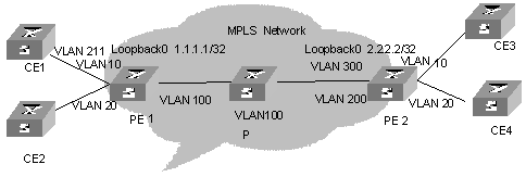
Figure 5-1 Network diagram for BGP/MPLS VPN intermixing
III. Configuration procedure
1) Configure CE1
# Configure CE1 and CE2 as EBGP neighbors and import direct routes and static routes So that the VPN user routes of CE1 are imported into BGP routes and then advertised to PE1.
<CE1>system-view
[CE1] vlan 211
[CE1] interface vlan-interface 211
[CE1-vlan-interface211] ip address 10.10.10.10 255.255.255.0
[CE1-vlan-interface211] quit
[CE1] bgp 65410
[CE1-bgp] group vpna external
[CE1-bgp] peer 10.10.10.1 group vpna as-number 100
[CE1-bgp] import-route direct
[CE1-bgp] import-route static
& Note:
The configuration on CE2 is similar to that on CE1, so the configuration procedure is omitted.
2) Configure PE1
# Configure global MPLS.
[PE1] mpls lsr-id 1.1.1.1
[PE1] mpls
[PE1] mpls ldp
# Configure public network interface and enable MPLS on the interface.
[PE1] interface loopback0
[PE1-LoopBack0] ip address 1.1.1.1 32
[PE1-LoopBack0] quit
[PE1] vlan 100
[PE1-vlan100] port GigabitEthernet 2/2/1
[PE1-vlan100] interface vlan-interface 100
[PE1-vlan-interface100] ip address 196.168.1.1 255.255.255.0
[PE1-vlan-interface100] mpls
[PE1-vlan-interface100] mpls ldp enable
[PE1-vlan-interface100] quit
# Enable OSPF on the interface connecting PE1 and P router and the Loopback interface.
[PE1] ospf 1 route-id 1.1.1.1
[PE1-ospf-1] area 0
[PE1-ospf-1-area-0.0.0.0] network 196.168.1.0 0.0.0.255
[PE1-ospf-1-area-0.0.0.0] network 1.1.1.1 0.0.0.0
[PE1-ospf-1-area-0.0.0.0] quit
# Configure VPN-instance. The configuration of VPN B is similar to that of VPN A, so followed is only the configuration of VPN A.
<PE1> system-view
[PE1] ip vpn-instance vpna
[PE1-vpn-vpna] route-distinguisher 100:1
[PE1-vpn-vpna] vpn-target 100:1 both
[PE1-vpn-vpna] quit
# Configure ACL and redirection, and configure a basic IP ACL to permit all the IP packets in CE devices to be redirected.
[PE1] flow-template user-defined slot 3 dmac 0000-0000-0000 sip 0.0.0.0 vlan-id
[PE1] acl number 2000
[PE1-acl-basic-2000] rule 0 permit source any
[PE1-acl-basic-2000] quit
[PE1] acl number 4000
[PE1-acl-link-4000]rule 0 permit ingress 10 egress 00e0-fc99-6738 0000-0000-0000
[PE1-acl-link-4000] quit
![]() Caution:
Caution:
If the VRRP protocol is enabled on the VLAN port to which the source port of MPLS VPN redirection belongs, you must configure another ACL rule to redirect the packets whose destination address is the virtual MAC address of VRRP, so that ICMP packets whose destination address is the virtual MAC address of VRRP can be processed normally.
# Configure VLAN interface.
[PE1] vlan 10
[PE1-vlan10] interface vlan-interface 10
[PE1-vlan-interface10] quit
# Configure redirection on ports.
[PE1] interface Ethernet 3/1/1
[PE1-Ethernet3/1/1] flow-template user-defined
[PE1-Ethernet3/1/1] traffic-redirect inbound ip-group 2000 rule 0 link-group 4000 rule 0 interface GigabitEthernet 2/1/1 10 l3-vpn
[PE1-Ethernet3/1/1] quit
# Bind VPN A to the VLAN port connecting PE1 and CE1.
[PE1] interface vlan-interface 10
[PE1-vlan-interface10] ip binding vpn-instance vpna
[PE1-vlan-interface10] ip address 10.10.10.1 255.255.255.0
[PE1-vlan-interface10] quit
# Establish EBGP neighbor relationship between PE1 and CE1 and import the interface routes of VPN-instance.
[PE1] bgp 100
[PE1-bgp] ipv4-family vpn-instance vpna
[PE1-bgp-af-vpn-instance] group vpna external
[PE1-bgp-af-vpn-instance] peer 10.10.10.10 group vpna as-number 65410
[PE1-bgp-af-vpn-instance] import-route direct
[PE1-bgp-af-vpn-instance] quit
[PE1-bgp] quit
# Establish MBGP neighbor relationship between PE and PE to exchange the VPN routing information between the PEs and activate IBGP peers in VPNv4 address family view.
[PE1] bgp 100
[PE1-bgp] group 100
[PE1-bgp] peer 2.2.2.2 group 100
[PE1-bgp] peer 2.2.2.2 connect-interface loopback0
[PE1-bgp] ipv4-family vpnv4
[PE1-bgp-af-vpn] peer 100 enable
[PE1-bgp-af-vpn] peer 2.2.2.2 group 100
3) Configure P
# Configure global MPLS.
[P] mpls lsr-id 3.3.3.3
[P] mpls
[P] mpls ldp
# Configure an interface and enable MPLS on the interface.
[P] interface loopback0
[P-LoopBack0] ip address 3.3.3.3 32
[P-LoopBack0] quit
[P] vlan 100
[P-vlan100] port GigabitEthernet 2/1/1
[P-vlan100] interface vlan-interface 100
[P-vlan-interface100] ip address 196.168.1.2 255.255.255.0
[P-vlan-interface100] mpls
[P-vlan-interface100] mpls ldp enable
[P-vlan-interface100] quit
[P] vlan 200
[P-vlan200] port GigabitEthernet 2/1/2
[P-vlan200] interface vlan-interface 200
[P-vlan-interface200] ip address 196.168.2.2 255.255.255.0
[P-vlan-interface200] mpls
[P-vlan-interface200] mpls ldp enable
[P-vlan-interface200] quit
# Configure OSPF.
[P] ospf 1 route-id 3.3.3.3
[P-ospf-1] area 0
[P-ospf-1-area-0.0.0.0] network 196.168.1.0 0.0.0.255
[P-ospf-1-area-0.0.0.0] network 196.168.2.0 0.0.0.255
[P-ospf-1-area-0.0.0.0] network 3.3.3.3 0.0.0.0
4) Configure PE2
# Configure global MPLS.
[PE2] mpls lsr-id 2.2.2.2
[PE2] mpls
[PE2] mpls ldp
# Configure a public network interface and enable MPLS on the interface.
[PE2] interface loopback0
[PE2-LoopBack0] ip address 2.2.2.2 32
[PE2-LoopBack0] quit
[PE2] vlan 300
[PE2-vlan300] port GigabitEthernet 2/2/1
[PE2-vlan300] interface vlan-interface 300
[PE2-vlan-interface300] ip address 196.168.2.1 255.255.255.0
[PE2-vlan-interface300] mpls
[PE2-vlan-interface300] mpls ldp enable
[PE2-vlan-interface300] quit
# Enable OSPF on the interface connecting PE2 with P router and the Loopback interface.
[PE2] ospf 1 route-id 2.2.2.2
[PE2-ospf-1] area 0
[PE2-ospf-1-area-0.0.0.0] network 196.168.1.0 0.0.0.255
[PE2-ospf-1-area-0.0.0.0] network 2.2.2.2 0.0.0.0
[PE1-ospf-1-area-0.0.0.0] quit
# Configure VPN-instance. The configuration of VPN B is similar to that of VPN A, so followed is only the configuration of VPN A.
[PE2] ip vpn-instance vpna
[PE2-vpn-vpna] route-distinguisher 100:1
[PE2-vpn-vpna] vpn-target 100:1 both
[PE2-vpn-vpna] quit
# Configure ACL, redirection and Layer 2 ACL (Custom flow template should be configured before this step).
[PE2] acl number 2000
[PE2-acl-basic-2000] rule 0 permit source any
[PE2-acl-basic-2000] quit
[PE2] flow-template user-defined slot 3 dmac 0000-0000-0000 sip 0.0.0.0 vlan-id
[PE2] acl number 4000
[PE2-acl-link-4000] rule 0 permit ingress 10 egress 00e0-fc99-6738 0000-0000-0000
[PE2-acl-link-4000] quit
# Configure VLAN interface.
[PE2] vlan 10
[PE2-vlan10] interface vlan-interface 10
[PE2-vlan-interface10] quit
# Configure redirection on the port.
[PE2] interface Ethernet 3/1/1
[PE2-Ethernet3/1/1] port link-type trunk
[PE2-Ethernet3/1/1] flow-template user-defined
[PE2-Ethernet3/1/1] traffic-redirect inbound ip-group 2000 rule 0 link-group 4000 rule 0 interface GigabitEthernet 2/1/1 10 l3-vpn
# Bind VPN A on the VLAN interface between PE2 and CE3.
[PE2] interface vlan-interface 10
[PE2-vlan-interface10] ip binding vpn-instance vpna
[PE2-vlan-interface10] ip address 20.2.1.2 255.255.255.0
[PE2-vlan-interface10] quit
# Import the interface routes of private network between PE2 and CE 3 for VPNA.
[PE2] bgp 100
[PE2-bgp] ipv4-family vpn-instance vpna
[PE2-bgp-af-vpn-instance] import-route direct
[PE2-bgp-af-vpn-instance] quit
[PE2-bgp] quit
# Establish MBGP neighbor relationship between PE and PE to exchange VPN routing information between PEs and activate IBGP peers in VPNv4 address family view.
[PE2] bgp 100
[PE2-bgp] group 100
[PE2-bgp] peer 1.1.1.1 group 100
[PE2-bgp] peer 1.1.1.1 connect-interface loopback0
[PE2-bgp] ipv4-family vpnv4
[PE2-bgp-af-vpn] peer 100 enable
[PE2-bgp-af-vpn] peer 1.1.1.1 group 100
& Note:
The configuration of L2 VPN VLL intermixing is similar to that of L3VPN intermixing, so the description of configuration process is omitted. The configuration of L2 VPN VLL intermixing is also implemented through the traffic-redirect command. You do not need to customize the flow template needed for VLL redirection and you can use the default flow template. In addition, the flow template only needs to match Layer 2 ACL of 4000 series and only the VLAN ID needs to be specified in ACL rules.
5.4 Restrictions in Networking of Various MPLS Cards
& Note:
MPLS cards with suffix CA support VLL and BGP/MPLS VPN, and common MPLS cards (with suffix C0) do not support VLL.
5.4.1 Exclusively non-MPLS Cards
I. Introduction to networking
Non-MPLS cards do not support related MPLS functions.
II. Configuration restrictions
If related MPLS service is configured, the service cannot work normally.
5.4.2 Exclusively MPLS Cards
I. Introduction to networking
MPLS cards support MPLS VPN (VLL and BGP/MPLS VPN), and VLL and BGP/MPLS VPN can be configured on MPLS cards at the same time.
II. Configuration restrictions
l Not supporting VPLS;
l VLL and BGP/MPLS VPN cannot be configured on a VLAN interface at the same time.
5.4.3 Exclusively VPLS Service Cards
I. Introduction to networking
This networking mode does not exist. Other service cards are needed to forward data.
II. Configuration restrictions
None.
5.4.4 Combination of One MPLS Card and Multiple non-MPLS Cards
I. Introduction to networking
The deployment of MPLS VPN (VLL and BGP/MPLS VPN) services can be implemented on non-MPLS cards through card intermixing configuration.
II. Configuration restrictions
l VLL and BGP/MPLS VPN are mutually exclusive, so it is not allowed to configure the two types of services on the same VLAN interface;
l In card intermixing networking, non-MPLS cards can only be used for access at the private network side, and MPLS card must be used for access at the public network side.
l MPLS card has influence on the forwarding performance of a switch.
5.4.5 Combination of Multiple MPLS cards and Multiple non-MPLS Cards
I. Introduction to networking
The combination of multiple MPLS cards and multiple non-MPLS cards is similar to “Combination of one MPLS card and multiple non-MPLS cards” in Section 5.4.4; however, MPLS VPN services can be processed on the MPLS cards directly, without the need of card intermixing configuration.
II. Configuration restrictions
It is not allowed to bind VLL and BGP/MPLS VPN to the same VLAN.
5.4.6 Combination of One VPLS Card and Multiple non-MPLS Cards
I. Introduction to networking
A VPLS card supports VPLS. However, a VPLS card does not have egress interfaces, so another interface card must be used data forwarding.
5.4.7 Combination of One VPLS card and Multiple MPLS Cards
I. Introduction to networking
VPLS cards can work with any type of interface cards to support VPLS.
5.4.8 Combination of One VPLS card, One MPLS Card and Multiple non-MPLS Cards
I. Introduction to networking
Assume only non-MPLS cards were used at the beginning, and then one MPLS card was added to support MPLS VPN services (VLL and BGP/MPLS VPN) through card intermixing configuration. Then one VPLS card was added to process VPLS services.
II. Configuration restrictions
The MPLS card is used to process MPLS VPN services. It is recommended to use non-MPLS cards for the access of MPLS services at the private network side.