- Table of Contents
-
- H3C S9500 Series Routing Switches Operation Manual-(V1.01)
- 00-1Cover
- 01-Getting Started Operation
- 02-Port Operation
- 03-VLAN-QinQ Operation
- 04-Network Protocol Operation
- 05-Routing Protocol Operation
- 06-Multicast Protocol Operation
- 07-QACL Operation
- 08-MPLS Operation
- 09-STP Operation
- 10-Security Operation
- 11-Reliability Operation
- 12-System Management Operation
- 13-PoE Operation
- 14-NAT-URPF-VPLS Operation
- 15-Integrated Management Operation
- 16-Appendix
- Related Documents
-
| Title | Size | Download |
|---|---|---|
| 01-Getting Started Operation | 393 KB |
Table of Contents
Chapter 2 Logging in to Switch
2.1 Setting Up Configuration Environment through the Console Port
2.2 Setting up Configuration Environment through Telnet
2.2.1 Connecting a PC to the Switch through Telnet
2.2.2 Accessing a Switch through another Switch via Telnet
2.3 Setting Up Configuration Environment through Modem Dial-up
Chapter 3 Command Line Interface
3.3 Features and Functions of Command Line
3.3.1 Online Help of Command Line
3.3.2 Displaying Characteristics of Command Line
3.3.3 History Command of Command Line
3.3.4 Common Command Line Error Messages
3.3.5 Editing Characteristics of Command Line
Chapter 4 User Interface Configuration
4.2 User Interface Configuration
4.2.1 Entering User Interface View
4.2.3 Configuring Asynchronous Port Attributes
4.2.4 Configuring Terminal Attributes
4.2.6 Configuring Modem Attributes
4.3 Displaying and Debugging User Interface
Chapter 5 Management Interface Configuration
5.1 Management Interface Overview
5.2 Management Interface Configuration
Chapter 6 Password Control Configuration
6.1 Introduction to Password Control Configuration
6.2 Password Control Configuration
6.2.1 Configuration Prerequisites
6.2.4 Password Control Configuration Example
Chapter 1 Product Overview
1.1 Product Overview
The H3C S9500 Series Routing Switches (hereinafter referred to as S9500 series) are a series of large capacity, modularized L2/L3 switches. They are mainly designed for broadband MAN, backbone, switching core and convergence center of large-sized enterprise network and campus network. They provide diverse services and can be used in constructing stable and high-performance IP network. The series include the following main models:
l S9505 routing switch
l S9508 routing switch
l S9512 routing switch
S9500 series use integrated chassis, which can be subdivided into power supply area, board area, backplane and fan area.
For S9505, in the board area, there are seven slots: the top two (slot0, slot1) accommodate SRPU boards, which are in 1+1 redundancy; the remaining five accommodate LPU boards, which can be hybrid.
For S9508, in the board area, there are 10 slots: the two (slot4, slot5) in the middle accommodate SRPU boards, which are in 1+1 redundancy; the remaining 8 accommodate LPU boards, which can be hybrid.
For S9512, in the board area, there are 14 slots: the two (slot6, slot7) in the middle accommodate SRPU boards, which are in 1+1 redundancy; the remaining 12 accommodate LPU boards, which can be hybrid. For specific configurations of the hybrid boards, refer to the “BGP/MPLS VPN Configuration” section of the MPLS module.
S9500 series support the following services:
l Internet broadband access
l MAN, enterprise/campus networking
l Providing multicast service and multicast routing and supporting multicast audio and video services.
1.2 Function Features
|
Features |
Implementation |
|
VLAN |
Supports VLAN compliant with IEEE 802.1Q Standard Supports port-based VLAN Supports GARP VLAN Registration Protocol (GVRP) Supports super VLAN Supports guest VLAN |
|
STP protocol |
Supports Spanning Tree Protocol (STP) / Multiple Spanning Tree Protocol (MSTP), compliant with IEEE 802.1D/IEEE 802.1s Standard |
|
Flow control |
Supports IEEE 802.3x flow control (full-duplex) Supports back-pressure based flow control (half-duplex) |
|
Broadcast Suppression |
Supports Broadcast Suppression |
|
Multicast |
Supports Internet Group Management Protocol Snooping (IGMP Snooping) Supports Internet Group Management Protocol (IGMP) Supports Protocol-Independent Multicast-Dense Mode (PIM-DM) Supports Protocol-Independent Multicast-Sparse Mode (PIM-SM) Supports Multicast Source Discovery Protocol (MSDP) Supports Multiprotocol BGP (MBGP) |
|
IP routing |
Supports static routing Supports Routing Information Protocol (RIP) v1/v2 Supports Open Shortest Path First (OSPF) Supports Border Gateway Protocol (BGP) Supports Intermediate System-to-Intermediate System intra-domain routing information exchange protocol (IS-IS) Supports equivalent routes Supports policy routing Supports IP routing policy |
|
DHCP |
Supports dynamic host configuration protocol (DHCP) relay Supports DHCP server |
|
Link aggregation |
Supports link aggregation, including manual aggregation and dynamic LACP (link aggregation control protocols) aggregation and static LACP aggregation. |
|
Mirroring |
Supports the port-based mirroring Supports flow mirroring of copying messages to CPU |
|
Quality of Service (QoS) |
Supports traffic classification Supports bandwidth control Supports congestion control Supports traffic shaping and traffic supervision Supports queues of different priority on the port Queue scheduling: supports Strict Priority Queuing (SP), Weighted Round Robin (WRR), and SP+WRR |
|
Security features |
Supports Multi-level user management and password protect Supports 802.1X authentication Supports Packet filtering Supports AAA/RADIUS/HWTACACS Supports IDS linkage |
|
MPLS |
Supports Multiprotocol Label Switching (MPLS) basic function Supports MPLS L3 VPN Supports VLL, including Martini, Kompella and CCC modes Supports VPLS |
|
Dedicated service processing |
Supports NAT Supports URPF |
|
Management and Maintenance |
Supports command line interface configuration Supports local configuration via Console port and AUX port Supports local and remote configuration through Telnet on Ethernet port Supports remote configuration through modem dialup via the AUX port. Supports SNMP management (Supports RMON (remote monitoring) MIB Groups 1, 2, 3 and 9) Supports system logging Supports level alarms Supports output of the debugging information Supports Ping and Tracert Supports remote maintenance via Telnet and Modem dialup Supports SSH (secure shell) 2.0 |
|
Loading and updating |
Supports to load and upgrade software via XModem protocol Supports to load and upgrade software via File Transfer Protocol (FTP) and Trivial File Transfer Protocol (TFTP) |
Chapter 2 Logging in to Switch
2.1 Setting Up Configuration Environment through the Console Port
Step 1: As shown in the figure below, to set up the local configuration environment, connect the serial port of a PC (or a terminal) to the Console port of the switch with the Console cable.
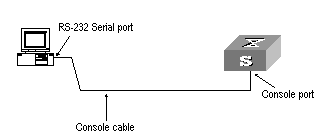
Figure 2-1 Set up the local configuration environment through the Console port
Step 2: Run a terminal emulator (such as Terminal of Windows 3X or HyperTerminal of Windows 9X) on the computer. Set the terminal communication parameters as follows: Set “Bits per second” to “9600”, “Data bits” to “8”, “Parity” to “none”, “Stop bits” to “1”, and “Flow control” to “none”, and select the “VT100” as the terminal type..
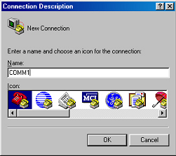
Figure 2-2 Set up new connection
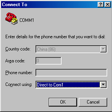
Figure 2-3 Configure the port for connection
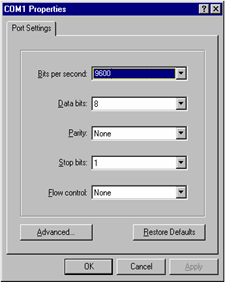
Figure 2-4 Set communication parameters
Step 3: The switch is powered on. Display self-test information of the switch and prompt you to press Enter to show the command line prompt such as <H3C>.
Step 4: Input a command to configure the switch or view the operation state. Input a “?” for help. For details of specific commands, refer to the following chapters.
2.2 Setting up Configuration Environment through Telnet
2.2.1 Connecting a PC to the Switch through Telnet
After you have correctly configured IP address of a VLAN interface for a switch via Console port (using ip address command in VLAN interface view), and added the port (that connects to a terminal) to this VLAN (using port command in VLAN view), you can telnet this switch and configure it.
Step 1: Before logging into the switch through telnet, you need to configure the Telnet user name and password on the switch through the console port.
& Note:
By default, the password is required for authenticating the Telnet user to log in to the switch. If a user logs in via the Telnet without password, he will see the prompt “Login password has not been set !”.
<H3C> system-view
Enter system view , return user view with Ctrl+Z.
[H3C] user-interface vty 0
[H3C-ui-vty0] set authentication password simple xxxx (xxxx is the login password of Telnet user)
Step 2: To set up the configuration environment, connect the Ethernet port of the PC to that of the switch via the LAN, as shown in Figure 2-5.
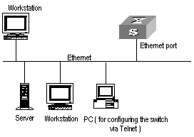
Figure 2-5 Set up configuration environment through telnet
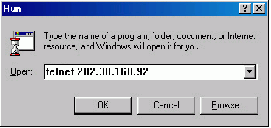
Step 3: Run Telnet on the PC and input the IP address of the VLAN connected to the PC port, as shown in Figure 2-6.
Step 4: The terminal displays “Login authentication!” and prompts the user to input the logon password. After you input the correct password, it displays the command line prompt (such as <H3C>). If the prompt “All user interfaces are used, please try later! The connection was closed by the remote host!” appears, it indicates that the maximum number of Telnet users that can be accessed to the switch is reached at this moment. In this case, please reconnect later. At most 5 Telnet users are allowed to log on to the H3C series switches simultaneously.
Step 5: Use the corresponding commands to configure the switch or to monitor the running state. Enter “?” to get the immediate help. For details of specific commands, refer to the following chapters.
& Note:
l When configuring the switch via Telnet, do not modify the IP address of it unless necessary, for the modification might cut the Telnet connection.
l By default, when a Telnet user passes the password authentication to log on to the switch, he can access the commands at Level 0.
2.2.2 Accessing a Switch through another Switch via Telnet
After a user has logged in to a switch, he or she can configure another switch through the switch via Telnet. The local switch serves as Telnet client and the peer switch serves as Telnet server. If the ports connecting these two switches are in a same local network, their IP addresses must be configured in the same network segment. Otherwise, the two switches must establish a route that can reach each other.
As shown in the figure below, after you telnet to a switch, you can run telnet command to log in and configure another switch.
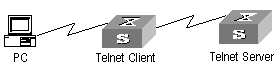
Figure 2-7 Provide Telnet Client service
Step 1: Configure the Telnet user name and password on the Telnet Server through the console port.
& Note:
By default, the password is required for authenticating the Telnet user to log in to the switch. If a user logs in via the Telnet without password, he will see the prompt “Login password has not been set !.”.
<H3C> system-view
System View: return to User View with Ctrl+Z
[H3C] user-interface vty 0
[H3C-ui-vty0] set authentication password simple xxxx (xxxx is the login password of Telnet user)
Step 2: The user logs in the Telnet Client (switch). For the login process, refer to the section describing “Connecting a PC to the Switch through Telnet”.
Step 3: Perform the following operations on the Telnet Client:
<H3C> telnet xxxx (xxxx can be the hostname or IP address of the Telnet Server. If it is the hostname, you need to use the ip host command to specify.)
Step 4: Enter the preset login password and you will see the prompt such <H3C>. If the prompt “All user interfaces are used, please try later! The connection was closed by the remote host!” appears, it indicates that the maximum number of Telnet users that can be accessed to the switch is reached at this moment. In this case, please connect later.
Step 5: Use the corresponding commands to configure the switch or view it running state. Enter “?” to get the immediate help. For details of specific commands, refer to the following chapters.
2.3 Setting Up Configuration Environment through Modem Dial-up
Step 1: The modem user is authenticated via the Console port of the switch before he or she logs in to the switch through a dial-up Modem.
& Note:
By default, the password is required for authenticating the Modem user to log in to the switch. If a user logs in via the Modem without password, he or she will see the prompt “Login password has not been set !.”.
<H3C> system-view
System View: return to User View with Ctrl+Z..
[H3C] user-interface aux 0
[H3C-ui-aux0] set authentication password simple xxxx (xxxx is the login password of the Modem user.)
Step 2: As shown in the figure below, to set up the remote configuration environment, connect the Modems to a PC (or a terminal) serial port and the switch AUX port respectively.
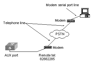
Figure 2-8 Set up remote configuration environment
Step 3: Dial for connection to the switch, using the terminal emulator and Modem on the remote end. The number dialed shall be the telephone number of the Modem connected to the switch. See the two figures below.
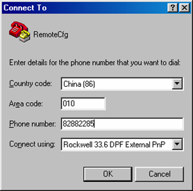
Figure 2-9 Set the dialed number
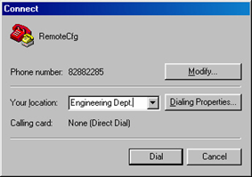
Figure 2-10 Dial on the remote PC
Step 4: Enter the preset login password on the remote terminal emulator and wait for the prompt such as <H3C>. Then you can configure and manage the switch. Enter “?” to get the immediate help. For details of specific commands, refer to the following chapters.
& Note:
By default, when a Modem user logs in, he can access the commands at Level 0.
Chapter 3 Command Line Interface
3.1 Command Line Interface
H3C series switches provide a series of configuration commands and command line interfaces for configuring and managing the switch. The command line interface has the following characteristics:
l Local configuration via the Console port and AUX port.
l Local or remote configuration via Telnet.
l Remote configuration through dialing with modem via the AUX port.
l Hierarchy command protection to avoid the unauthorized users accessing switch.
l Enter a “?” to get immediate online help.
l Provide network testing commands, such as Tracert and Ping, to fast troubleshoot the network.
l Provide various detailed debugging information to help with network troubleshooting.
l Log in and manage other switch directly, using the Telnet command.
l Provide FTP service for the users to upload and download files.
l Provide the function similar to Doskey to execute a history command.
l The command line interpreter searches for target not fully matching the keywords. It is ok for you to key in the whole keyword or part of it, as long as it is unique and not ambiguous.
3.2 Command Line View
H3C series switches provide hierarchy protection for the command lines to avoid unauthorized user accessing illegally.
Commands are classified into four levels, namely visit level, monitoring level, configuration level and management level. They are introduced as follows:
l Visit level: Commands of this level involve command of network diagnosis tool (such as ping and tracert), command of switch between different language environments of user interface (language-mode) and telnet command etc. The operation of saving configuration file is not allowed on this level of commands.
l Monitoring level: Commands of this level, including the display command and the debugging command, are used to system maintenance, service fault diagnosis, etc. The operation of saving configuration file is not allowed on this level of commands.
l Configuration level: Service configuration commands, including routing command and commands on each network layer, are used to provide direct network service to the user.
l Management level: They are commands that influence basis operation of the system and system support module, which plays a support role on service. Commands of this level involve file system commands, FTP commands, TFTP commands, XModem downloading commands, user management commands, and level setting commands.
At the same time, login users are classified into four levels that correspond to the four command levels respectively. After users of different levels log in, they can only use commands at the levels that are equal to or lower than its own level.
In order to prevent unauthorized users from illegal intrusion, user will be identified when switching from a lower level to a higher level with super [ level ] command. User ID authentication is performed when users at lower level switch to users at higher level. In other words, user password of the higher level is needed (Suppose the user has set the super password [ level level ] { simple | cipher } password.) For the sake of confidentiality, on the screen the user cannot see the password that he entered. Only when correct password is input for three times, can the user switch to the higher level. Otherwise, the original user level will remain unchanged.
Different command views are implemented according to different requirements. They are related to one another. For example, after logging in the switch, you will enter user view, in which you can only use some basic functions such as displaying the running state and statistics information. In user view, key in system-view to enter system view, in which you can key in different configuration commands and enter the corresponding views.
The command line provides the following views:
l User view
l System view
l Port view
l VLAN view
l VLAN interface view
l Local-user view
l User interface view
l FTP Client command view
l SFTP Client view
l MST region view
l PIM view
l MSDP view
l IPv4 multicast sub-address family view
l RIP view
l OSPF view
l OSPF area view
l BGP view
l IS-IS view
l Route policy view
l Basic ACL view
l Advanced ACL view
l Layer-2 ACL view
l Conform-level view
l WRED index view
l RADIUS server group view
l ISP domain view
l MPLS view
l VPNv4 sub-address family view
l VPN-instance sub-address family view
l BGP-VPNv4 sub-address family view
l MPLS L2VPN view
l L2VPN address family view
l Route-Policy view
l vpn-instance view
l OSPF protocol view
l Remote-peer view
l VSI-LDP view
l VSI view
l HWTACACS view
l Port group view
l Lanswitch view
l HGMP view
The following table describes the function features of different views and the ways to enter or quit.
Table 3-1 Function feature of command view
|
Command view |
Function |
Prompt |
Command to enter |
Command to exit |
|
User view |
Show the basic information about operation and statistics |
<H3C> |
Enter right after connecting the switch |
Use quit to end the disconnection with the switch |
|
System view |
Configure system parameters |
[H3C] |
Key in system-view in user view |
Use quit or return to return to user view |
|
Port view |
Ethernet port view: Configure Ethernet port parameters |
100M Ethernet port view Key in interface ethernet 2/1/1 in system view |
Use quit to return to system view Use return to return to user view |
|
|
[H3C-GigabitEthernet2/1/1] |
GigabitEthernet port view Key in interface gigabitethernet 2/1/1 in system view |
|||
|
[H3C-GigabitEthernet2/1/1] |
10G Ethernet port view Key in interface gigabitethernet 2/1/1 in system view |
|||
|
POS port view: Configure POS port parameters |
[H3C-Pos2/1/1] |
Key in interface pos 2/1/1 in system view |
||
|
RPR logical port view: Configure RPR port parameters |
[H3C-rpr2/1/1] |
Key in interface rpr2/1/1 in system view |
||
|
RPR POS physical port view: Configure physical parameters for RPR ports |
[H3C-rpr2/1/1.1] |
Key in interface rpr2/1/1.1 in system view |
||
|
VLAN view |
Configure VLAN parameters |
[H3C-Vlan1] |
Key in vlan 1 in system view |
Use quit to return to system view Use return to return to user view |
|
VLAN interface view |
Configure IP interface parameters for a VLAN or a VLAN aggregation |
[H3C-Vlan-interface1] |
Key in interface vlan-interface 1 in system view |
Use quit to return to system view Use return to return to user view |
|
Local-user view |
Configure local user parameters |
[H3C-luser-user1] |
Key in local-user user1 in system view |
Use quit to return to system view Use return to return to user view |
|
User interface view |
Configure user interface parameters |
[H3C-ui0] |
Key in user-interface 0 in system view |
Use quit to return to system view Use return to return to user view |
|
FTP client command view |
Configure FTP Client parameters |
[ftp] |
Key in ftp in user view |
Use quit to return to system view |
|
SFTP Client view |
Configure SFTP Client parameters |
<sftp-client> |
Key in sftp ip-address in system view |
Use quit to return to system view Use return to return to user view |
|
MST region view |
Configure MST region parameters |
[H3C-mst-region] |
Key in stp region-configuration in system view |
Use quit to return to system view Use return to return to user view |
|
PIM view |
Configure PIM parameters |
[H3C-PIM] |
Key in pim in system view |
Use quit to return to system view Use return to return to user view |
|
MSDP view |
Configure MSDP parameters |
[H3C-msdp] |
Key in msdp in system view |
Use quit to return to system view Use return to return to user view |
|
IPv4 multicast sub-address family view |
Enter the IPv4 multicast sub-address family view to configure MBGP multicast extension parameters |
[H3C-bgp-af-mul] |
Key in ipv4-family multicast in BGP view |
Use quit to return to BGP view Use return to return to user view |
|
RIP view |
Configure RIP parameters |
[H3C-rip] |
Key in rip in system view |
Use quit to return to system view Use return to return to user view |
|
OSPF view |
Configure OSPF parameters |
[H3C-ospf] |
Key in ospf in system view |
Use quit to return to system view Use return to return to user view |
|
OSPF area view |
Configure OSPF area parameters |
[H3C-ospf-0.0.0.1] |
Key in area 1 in OSPF view |
Use quit to return to OSPF view Use return to return to user view |
|
BGP view |
Configure BGP parameters |
[H3C-bgp] |
Key in bgp 100 in system view |
Use quit to return to system view Use return to return to user view |
|
IS-IS view |
Configure IS-IS parameters |
[H3C-isis] |
Key in isis in system view |
Use quit to return to system view Use return to return to user view |
|
Route policy view |
Configure route policy parameters |
[H3C-route-policy] |
Key in route-policy policy1 permit node 10 in system view |
Use quit to return to system view Use return to return to user view |
|
Basic ACL view |
Define the rule of basic ACL |
[H3C-acl-basic-2000] |
Key in acl number 2000 in system view |
Use quit to return to system view Use return to return to user view |
|
Advanced ACL view |
Define the rule of advanced ACL |
[H3C-acl-adv-3000] |
Key in acl number 3000 in system view |
Use quit to return to system view Use return to return to user view |
|
Layer-2 ACL view |
Define the rule of layer-2 ACL |
[H3C-acl-link-4000] |
Key in acl number 4000 in system view |
Use quit to return to system view Use return to return to user view |
|
Conform-level view |
Configure the "DSCP + Conform-level Service group" mapping table and”EXP + Conform-level- >service parameters”mapping table and "Local-precedence + Conform-level 802.1p priority" mapping table |
[H3C-conform-level-0] |
Key in qos conform-level 0 in system view |
Use quit to return to system view Use return to return to user view |
|
WRED index view |
Configure WRED parameters |
[H3C-wred-0] |
Key in wred 0 in system view |
Use quit to return to system view Use return to return to user view |
|
RADIUS server group view |
Configure radius parameters |
[H3C-radius-1] |
Key in radius scheme 1 in system view |
Use quit to return to system view Use return to return to user view |
|
ISP domain view |
Configure ISP domain parameters |
[H3C-isp-H3C163.net] |
Key in domain H3C163.net in system view |
Use to return to system view Use return to return to user view |
|
MPLS view |
Configure MPLS parameters |
[H3C-mpls] |
Key in mpls in system view |
Use quit to return to system view Use return to return to user view |
|
VPNv4 sub-address family view |
Configure VPNv4 address family parameters |
[H3C-bgp-af-vpn] |
Key in ipv4-family vpnv4 in BGP view |
Use quit to return to system view Use return to return to user view |
|
VPN-instance sub-address family view |
Configure VPN instance sub-address family parameters |
[H3C-bgp-af-vpn-instance] |
Key in ipv4-family vpn-instance vpna in BGP/RIP view |
Use quit to return to system view Use return to return to user view |
|
BGP-VPNv4 sub-address family view |
Configure BGP-VPNv4 sub-address family parameters |
[H3C-bgp-af-vpn] |
Key in ipv4-family vpn-instance in BGP/RIP view |
Use quit to return to system view Use return to return to user view |
|
MPLS L2VPN view |
Configure MPLS L2VPN service parameters |
[H3C-mpls-l2vpn-vpna] |
Key in mpls l2vpn vpna encapsulation Ethernet in system view |
Use quit to return to system view Use return to return to user view |
|
L2VPN address family view |
Configure L2VPN service parameters |
[H3C-bgp-af-l2vpn] |
Key in l2vpn-family in BGP view |
Use quit to return to system view Use return to return to user view |
|
Route-Policy view |
Configure Route-Policy service parameters |
[H3C-route-policy] |
Key in route-policy route-policy-name { permit | deny } node node-number in system view |
Use quit to return to system view Use return to return to user view |
|
vpn-instance view |
Configure vpn-instance parameters |
[H3C-vpn-vpn-instance_blue] |
Key in ip vpn-instance vpn-instance_ vpna in system view |
Use quit to return to system view Use return to return to user view |
|
OSPF protocol view |
Configure OSPF protocol parameters |
[H3C-ospf-100] |
Key in ospf process-id [ router-id router-id-number ] [ vpn-instance vpn-instance-name ] in system view |
Use quit to return to system view Use return to return to user view |
|
Remote-peer view |
Configure MPLS peer group parameters |
[H3C-mpls-remote1] |
Key in mpls remote1 |
Use quit to return to system view Use return to return to user view |
|
VSI-LDP view |
Configure some VPLS features |
[9500-vsi-H3C-ldp] |
Key in vsi H3C in system view Key in pwsignal ldp in vsi view |
Use quit to return to vsi view Use return to return to user view |
|
VSI view |
Specify VPLS mode |
[9500-vsi-H3C] |
Key in vsi H3C in system view |
Use quit to return to system view Use return to return to user view |
|
HWTACACS view |
Configure HWTACACS protocol parameters |
[9500-hwtacacs-H3C] |
Key in hwtacacs scheme H3C in system view |
Use quit to return to system view Use return to return to user view |
|
Port group view |
Combine the ports with the same configuration, omitting repeated configuration procedure |
[9500-port-group X] |
Key in port-group X in system view |
Use quit to return to system view Use return to return to user view |
|
HGMP view |
Configure some HGMP features |
[H3C-hgmp] |
Key in hgmpserver enable in system view |
Use quit to return to system view Use return to return to user view |
|
Lanswitch view |
Enter lanswitch view. After entering the specified lanswitch view, you can use the specified Ethernet switch. |
[H3C-lanswitchX/X/X-/] |
Key in lanswitch X/X/X-/ in HGMP view |
Use quit to return to HGMP view Use return to return to user view |
3.3 Features and Functions of Command Line
3.3.1 Online Help of Command Line
The command line interface provides the following online help modes.
l Full help
l Partial help
You can get the help information through these online help commands, which are described as follows.
1) Input “?” in any view to get all the commands in it and corresponding descriptions.
<H3C> ?
User view commands:
language-mode Specify the language environment
ping Ping function
quit Exit from current command view
super Privilege current user a specified priority level
telnet Establish one TELNET connection
tracert Trace route function
2) Input a command with a “?” separated by a space. If this position is for keywords, all the keywords and the corresponding brief descriptions will be listed.
<H3C> language-mode ?
chinese Chinese environment
english English environment
3) Input a command with a “?” separated by a space. If this position is for parameters, all the parameters and their brief descriptions will be listed.
[H3C] garp timer leaveall ?
INTEGER<65-32765> Value of timer in centiseconds
(LeaveAllTime > (LeaveTime [On all ports]))
Time must be multiple of 5 centiseconds
[H3C] garp timer leaveall 300 ?
<cr>
<cr> indicates no parameter in this position. The next command line repeats the command, you can press <Enter> to execute it directly.
4) Input a character string with a “?”, then all the commands with this character string as their initials will be listed.
<H3C> p?
ping pwd
5) Input a command with a character string and “?”, then all the key words with this character string as their initials in the command will be listed.
<H3C> display ver?
version
6) Input the first letters of a keyword of a command and press <Tab> key. If no other keywords are headed by this letters, then this unique keyword will be displayed automatically.
7) To switch to the Chinese display for the above information, perform the language-mode command.
3.3.2 Displaying Characteristics of Command Line
Command line interface provides the following display characteristics:
l For users’ convenience, the instruction and help information can be displayed in both English and Chinese.
l For the information to be displayed exceeding one screen, pausing function is provided. In this case, users can have three choices, as shown in the table below.
Table 3-2 Functions of displaying
|
Key or Command |
Function |
|
Press <Ctrl+C> when the display pauses |
Stop displaying and executing command. |
|
Enter a space when the display pauses |
Continue to display the next screen of information. |
|
Press <Enter> when the display pauses |
Continue to display the next line of information. |
3.3.3 History Command of Command Line
Command line interface provides the function similar to that of DosKey. The commands entered by users can be automatically saved by the command line interface and you can invoke and execute them at any time later. History command buffer is defaulted as 10. The operations are shown in the table below.
Table 3-3 Retrieve history command
|
Operation |
Key |
Result |
|
Display history command |
display history-command |
Display history command by user inputting |
|
Retrieve the previous history command |
Up cursor key <↑> or <Ctrl+P> |
Retrieve the previous history command, if there is any. |
|
Retrieve the next history command |
Down cursor key <↓> or <Ctrl+N> |
Retrieve the next history command, if there is any. |
& Note:
Cursor keys can be used to retrieve the history commands in Windows 3.X Terminal and Telnet. However, in Windows 9X HyperTerminal, the cursor keys ↑ and ↓ do not work, because Windows 9X HyperTerminal defines the two keys differently. In this case, use the combination keys <Ctrl+P> and <Ctrl+N> instead for the same purpose.
3.3.4 Common Command Line Error Messages
All the input commands by users can be correctly executed, if they have passed the grammar check. Otherwise, error messages will be reported to users. The common error messages are listed in the following table.
Table 3-4 Common command line error messages
|
Error messages |
Causes |
|
Unrecognized command |
Cannot find the command. |
|
Cannot find the keyword. |
|
|
Wrong parameter type. |
|
|
The value of the parameter exceeds the range. |
|
|
Incomplete command |
The input command is incomplete. |
|
Too many parameters |
Enter too many parameters. |
|
Ambiguous command |
The parameters entered are not specific. |
3.3.5 Editing Characteristics of Command Line
Command line interface provides the basic command editing function and supports to edit multiple lines. A command cannot longer than 256 characters. See the table below.
|
Key |
Function |
|
Common keys |
Insert from the cursor position and the cursor moves to the right, if the edition buffer still has free space. |
|
Backspace |
Delete the character preceding the cursor and the cursor moves backward. |
|
Leftwards cursor key <←> or <Ctrl+B> |
Move the cursor a character backward |
|
Rightwards cursor key <→> or <Ctrl+F> |
Move the cursor a character forward |
|
Up cursor key <↑> or <Ctrl+P> Down cursor key <↓> or <Ctrl+N> |
Retrieve the history command. |
|
<Tab> |
Press <Tab> after typing the incomplete key word and the system will execute the partial help: If the key word matching the typed one is unique, the system will replace the typed one with the complete key word and display it in a new line; if there is not a matched key word or the matched key word is not unique, the system will do no modification but display the originally typed word in a new line. |
Chapter 4 User Interface Configuration
4.1 User Interface Overview
To facilitate system management, the switches support user interface based configuration for the configuration and management of port attributes. Presently, the S9500 series switches support the following user interface based configuration methods:
l Local configuration via the Console port and AUX port
l Local and remote configuration through Telnet on Ethernet port
l Remote configuration through dialing with modem via the AUX port.
According to the above-mentioned configuration methods, there are three types of user interfaces:
l Console user interface
Console user interface is used to log in to the switch via the Console port. A switch can only have one Console user interface.
l AUX user interface
AUX user interface is used to log in to the switch locally or remotely with a modem via the AUX port. A switch can only have one AUX user interface. The local configuration for it is similar to that for the Console user interface.
l VTY user interface
VTY user interface is used to telnet the switch. A switch can have up to five VTY user interface.
User interface is numbered in the following two ways: absolute number and relative number.
I. Absolute number
The user interfaces of the S9500 routing switch include three types, which are sequenced as follows: console interface (CON), auxiliary interface (AUX) and virtual interface (VTY). A switch has one CON, one AUX and multiple VTYs. The first absolute number is designated as 0; the second one is designated as 1; and so on. This method can specify a unique user interface or a group of interfaces.
It follows the rules below.
l Console user interface is numbered as the first interface designated as user interface 0.
l AUX user interface is numbered as the second interface designated as user interface 1.
l VTY is numbered after AUX user interface. The absolute number of the first VTY is incremented by 1 than the AUX user interface number.
II. Relative number
The relative number is in the format of “user interface type” + “number”. The “number” refers to the internal number for each user interface type. This method can only specify one interface or one group of interfaces for a user interface type instead of different user interface types.
It follows the rules below:
l Number of Console user interface: console 0.
l Number of AUX user interface: AUX 0.
l Number of VTY: The first VTY interface is designated as VTY 0; the second one is designated as VTY 1, and so on.
4.2 User Interface Configuration
The following sections describe the user interface configuration tasks.
l Entering User Interface View
l Configuring Asynchronous Port Attributes
l Configuring Terminal Attributes
l Configuring Modem Attributes
4.2.1 Entering User Interface View
The following command is used for entering a user interface view. You can enter a single user interface view or multi user interface view to configure one or more user interfaces respectively.
Perform the following configuration in system view.
Table 4-1 Enter user interface view
|
Operation |
Command |
|
Enter a single user interface view or multi user interface views |
user-interface [ type ] first-number [ last-number ] |
4.2.2 Define the Login Header
The following command is used for configuring the displayed header when user login.
When the users log in to the switch, if a connection is activated, the login header will be displayed. After the user successfully logs in the switch, the shell header will be displayed.
Perform the following configuration in system view.
Table 4-2 Configure the login header.
|
Operation |
Command |
|
Configure the login header |
header [ shell | incoming | login ] text |
|
Remove the login header configured |
undo header [ shell | incoming | login ] |
Note that if you press <Enter> after typing any of the three keywords shell, login and incoming in the command, then what you type after the word header is the contents of the login information, instead of identifying header type.
4.2.3 Configuring Asynchronous Port Attributes
The following commands can be used for configuring the attributes of the asynchronous port in asynchronous interactive mode, including speed, flow control, parity, stop bit and data bit.
Perform the following configurations in user interface (Console and AUX user interface only) view.
I. Configuring the transmission speed
Table 4-3 Configure the transmission speed
|
Operation |
Command |
|
Configure the transmission speed |
speed speed-value |
|
Restore the default transmission speed |
undo speed |
By default, the transmission speed on an asynchronous port is 9600bps.
II. Configuring flow control
Table 4-4 Configure flow control
|
Operation |
Command |
|
Configure the flow control |
flow-control { hardware | none | software } |
|
Restore the default flow control mode |
undo flow-control |
By default, the flow control on an asynchronous port is none, that is, no flow control will be performed.
III. Configuring parity
|
Operation |
Command |
|
Configure parity mode |
parity { even | mark | none | odd | space } |
|
Restore the default parity mode |
undo parity |
By default, the parity on an asynchronous port is none, that is, no parity bit.
IV. Configuring the stop bit
Table 4-6 Configure the stop bit
|
Operation |
Command |
|
Configure the stop bit |
stopbits { 1 | 1.5 | 2 } |
|
Restore the default stop bit |
undo stopbits |
By default, an asynchronous port supports 1 stop bit.
Note that setting 1.5 stop bits is not available on S9500 series at present.
V. Configuring the data bit
Table 4-7 Configure the data bit
|
Operation |
Command |
|
Configure the data bit |
databits { 7 | 8 } |
|
Restore the default data bit |
undo databits |
By default, an asynchronous port supports 8 data bits.
4.2.4 Configuring Terminal Attributes
The following commands can be used for configuring the terminal attributes, including enabling/disabling terminal service, disconnection upon timeout, lockable user interface, configuring terminal screen length and history command buffer size.
Perform the following configuration in user interface view. Perform lock command in user view.
I. Enabling/disabling terminal service
After the terminal service is disabled on a user interface, you cannot log in to the switch through the user interface. However, the user logged in through the user interface before disabling the terminal service can continue his operation. After such user logs out, he cannot log in again. In this case, a user can log in to the switch through the user interface only when the terminal service is enabled again.
Table 4-8 Enable/disable terminal service
|
Operation |
Command |
|
Enable terminal service |
shell |
|
Disable terminal service |
undo shell |
By default, terminal service is enabled on all the user interfaces.
Note the following points:
l For the sake of security, the undo shell command can only be used on the user interfaces other than Console user interface.
l You cannot use this command on the user interface via which you log in.
l You will be asked to confirm before using undo shell on any legal user interface.
II. Configuring idle-timeout
Table 4-9 Configure idle-timeout
|
Operation |
Command |
|
Configure idle-timeout |
idle-timeout minutes [ seconds ] |
|
Restore the default idle-timeout |
undo idle-timeout |
By default, idle-timeout is enabled and set to 10 minutes on all the user interfaces. That is, the user interface will be disconnected automatically after 10 minutes without any operation.
idle-timeout 0 means disabling idle-timeout.
III. Locking user interface
This configuration is to lock the current user interface and prompt the user to enter the password. This makes it impossible for others to operate in the interface after the user leaves.
Table 4-10 Lock user interface
|
Operation |
Command |
|
Lock user interface |
lock |
IV. Setting the screen length
If a command displays more than one screen of information, you can use the following command to set how many lines to be displayed in a screen, so that the information can be separated in different screens and you can view it more conveniently.
Table 4-11 Set the screen length
|
Operation |
Command |
|
Set the screen length |
screen-length screen-length |
|
Restore the default screen length |
undo screen-length |
Note that the number of lines that can be displayed in each screen remains the same when screen-length is set to 1 or 2.
By default, 24 lines (including the multi-screen identifier lines) are displayed in one screen when the multi-screen display function is enabled .
Use screen-length 0 to disable the multi-screen display function.
V. Setting the history command buffer size
Table 4-12 Set the history command buffer size
|
Operation |
Command |
|
Set the history command buffer size |
history-command max-size value |
|
Restore the default history command buffer size |
undo history-command max-size |
By default, the size of the history command buffer is 10, that is, 10 history commands can be saved.
4.2.5 Managing Users
The management of users includes the setting of user logon authentication method, level of command which a user can use after logging on, level of command which a user can use after logging on from the specifically user interface, and command level.
I. Configuring the authentication method
The following command is used for configuring the user login authentication method to deny the access of an unauthorized user.
Perform the following configuration in user interface view.
Table 4-13 Configure the authentication method
|
Operation |
Command |
|
Configure the authentication method |
authentication-mode { password | scheme | none } |
By default, terminal authentication is not required for local users log in via the Console port. However, password authentication is required for local users and remote Modem users to log in via the AUX port, and for Telnet users and the VTY users to log in through Ethernet port.
Note: If the Console port is configured for local password authentication, the user can directly log in to the system even without a password configured; if other user interfaces, such as the AUX port and VTY interface, are configured for local password authentication, users cannot log in to the system without a password.
1) Perform local password authentication to the user interface
Using authentication-mode password command, you can perform local password authentication. That is, you need use the command below to configure a login password in order to login successfully.
Perform the following configuration in user interface view.
Table 4-14 Configure the local authentication password
|
Operation |
Command |
|
Configure the local authentication password |
set authentication password { cipher | simple }password |
|
Remove the local authentication password |
undo set authentication password |
# Configure for password authentication when a user logs in through a VTY 0 user interface and set the password to H3C.
[H3C] user-interface vty 0
[H3C-ui-vty0] authentication-mode password
[H3C-ui-vty0] set authentication password simple H3C
2) Perform local or remote authentication of username and password to the user interface
Using authentication-mode scheme command, you can perform local or remote authentication of username and password. The type of the authentication depends on your configuration. For detailed information, see “Security” section.
In the following example, local username and password authentication are configured.
# Perform username and password authentication when a user logs in through VTY 0 user interface and set the username and password to zbr and H3C respectively.
[H3C-ui-vty0] authentication-mode scheme
[H3C-ui-vty0] quit
[H3C] local-user zbr
[H3C-luser-zbr] password simple H3C
[H3C-luser-zbr] service-type telnet
3) No authentication
[H3C-ui-vty0] authentication-mode none
& Note:
By default, password is required to be set for authenticating local users and remote Modem users log in via the AUX port, and Telnet users log in through Ethernet port. If no password has been set, the following prompt will be displayed “Login password has not been set !.”
If the authentication-mode none command is used, the local and Modem users via the AUX port and Telnet users will not be required to input password.
II. Setting the command level used after a user logging in
The following command is used for setting the command level used after a user logging in.
Perform the following configuration in local-user view.
Table 4-15 Set the command level used after a user logging in
|
Operation |
Command |
|
Set command level used after a user logging in |
service-type telnet [ level level ] |
|
Restore the default command level used after a user logging in |
undo service-type telnet |
By default, the specified logon user can access the commands at Level 2.
III. Setting the command level used after a user logs in from a user interface
You can use the following command to set the command level after a user logs in from a specific user interface, so that a user is able to execute the commands at such command level.
Perform the following configuration in user interface view.
Table 4-16 Set the command level used after a user logging in from a user interface
|
Operation |
Command |
|
Set command level used after a user logging in from a user interface |
user privilege level level |
|
Restore the default command level used after a user logging in from a user interface |
undo user privilege level |
By default, you can access the commands at Level 3 after logging in through the Console user interface, and the commands at Level 0 after logging in through the AUX or VTY user interface.
& Note:
When a user logs in the switch, the command level that it can access depends on two points. One is the command level that the user itself can access, the other is the set command level of this user interface. If the two levels are different, the former will be taken. For example, the command level of VTY 0 user interface is 1, however, you have the right to access commands of level 3; if you log in from VTY 0 user interface, you can access commands of level 3 and lower.
IV. Setting the command priority
The following command is used for setting the priority of a specified command in a certain view. The command levels include visit, monitoring, configuration, and management, which are identified with 0 through 3 respectively. An administrator assigns authorities as per user requirements.
Perform the following configuration in system view.
Table 4-17 Set the command priority
|
Operation |
Command |
|
Set the command priority in a specified view. |
command-privilege level level view view command |
|
Restore the default command level in a specified view. |
Undo command-privilege view view command |
V. Setting input protocol for a user terminal
You can use the following command to set input protocol for a user terminal. The input protocol type can be TELNET, SSH or all.
Perform the following configuration in user interface view.
Table 4-18 Set input protocol for a user terminal
|
Operation |
Command |
|
Set input protocol for a user terminal |
protocol inbound { all | telnet | ssh } |
By default, the input protocol type for a user terminal is all.
4.2.6 Configuring Modem Attributes
When logging in the switch via the Modem, you can use the following commands to configure these parameters.
Perform the following configuration in AUX user interface view.
Table 4-19 Configure Modem attributes
|
Operation |
Command |
|
Set the interval since the system receives the RING until CD_UP |
modem timer answer seconds |
|
Restore the default interval since the system receives the RING until CD_UP |
undo modem timer answer |
|
Configure auto answer |
modem auto-answer |
|
Configure manual answer |
undo modem auto-answer |
|
Configure to allow call-in |
modem call-in |
|
Configure to bar call-in |
undo modem call-in |
|
Configure to permit call-in and call-out. |
modem both |
|
Configure to disable call-in and call-out |
undo modem both |
4.2.7 Configuring Redirection
I. Send command
The following command can be used for sending messages between user interfaces.
Perform the following configuration in user view.
Table 4-20 Configure to send messages between different user interfaces.
|
Operation |
Command |
|
Configure to send messages between different user interfaces. |
send { all | number | type number } |
II. Auto-execute command
The following command is used to automatically run a command after you log in. After a command is configured to be run automatically, it will be automatically executed when you log in again.
This command is usually used to automatically execute telnet command on the terminal, which will connect the user to a designated device automatically.
Perform the following configuration in user interface view.
Table 4-21 Configure to automatically run the command
|
Operation |
Command |
|
Configure to automatically run the command |
auto-execute command text |
|
Configure not to automatically run the command |
undo auto-execute command |
Note the following points:
l After executing this command, the user interface can no longer be used to carry out the routine configurations for the local system. Use this command with caution.
l Make sure that you will be able to log in to the system in some other way and cancel the configuration, before you use the auto-execute command command and save the configuration.
# Telnet 10.110.100.1 after the user logs in through VTY0 automatically.
[H3C-ui-vty0] auto-execute command telnet 10.110.100.1
When a user logs on via VTY 0, the system will run telnet 10.110.100.1 automatically.
4.3 Displaying and Debugging User Interface
After the above configuration, execute display command in any view to display the running of the user interface configuration, and to verify the effect of the configuration.
Execute free command in user view to release the user interface connection.
Table 4-22 Display and debug user interface
|
Operation |
Command |
|
Release a specified user interface connection |
free user-interface [ type ] number |
|
Display the user application information of the user interface |
display users [ all ] |
|
Display the physical attributes and some configurations of the user interface |
display user-interface [ type number | number ] [ summary ] |
|
Query history commands selectively |
display history-command { Command-Number } { | { begin | include | exclude } Match-string } |
Chapter 5 Management Interface Configuration
5.1 Management Interface Overview
S9500 series provide a 10/100Base-TX management interface on their SRPU board. The management interface can connect a background PC for software loading and system debugging, or a remote network management station for remote system management.
5.2 Management Interface Configuration
The following sections describe management interface configuration tasks.
l Configuring interface IP address
l Enabling/disabling the interface
l Setting interface description
l Displaying current system information
l Test network connectivity (ping,tracert)
See the Port and System Management parts of this manual for details.
![]() Caution:
Caution:
Only the management interface configured with an IP address can run normally.
Chapter 6 Password Control Configuration
6.1 Introduction to Password Control Configuration
The Ethernet switch provides the password control function. Before a user can log in to the Ethernet switch, a system login password must be configured. After a password is configured, the user must enter the password each time he or she wants to log in to the switch. The user and can successfully log in to the switch and proceed with operations only if he or she passes the authentication. If the password authentication fails, the user will not be able to log in to the switch.
The user can either use the default password configuration, or perform his or her own password control configuration. When conducting password control, the user must follow the steps below:
1) Configuring system login password
If password authentication is required for a user to log in to the system, the system will protect the password, instead of displaying the input password in the command line. The password must not be displayed in plain text either in the system configuration file or on the terminal: the password must be encrypted be being stored.
When a user inputs the password, “******”, rather than the plain text of the user’s password, will appear on the terminal. When configuring a password, the user needs to input the password twice for confirmation. During password configuration, the password appears as “******” in the command line, and it appears in the form of encrypted text in the configuration file.
2) Enabling password control
After password configuration, the user can conduct password control, which includes the following aspects:
l Enabling password aging
l Enabling limitation of minimum password length
l Enabling history password recording
When a login password expires, the system will require the user to input a new password and will save the old password automatically. By recording the history passwords, the system can prevent the user from using a single password or repeated passwords when modifying a password, thus to enhance the security.
The system stores the history password records in a private file in the flash memory. This file is not accessible to any user. In addition, the system automatically backs up the history password records and blacklist records, specifically as follows:
l When adding or deleting a history password record, the system requests the standby card to perform backup.
l When purging all history records or the history records of a certain user, the system requests the standby card to perform backup.
l When adding a user to or deleting a user from the blacklist, the system requests the standby card to perform backup.
l The flash memory on the active card and that on the standby keeps the same copies of history password records and blacklist records.
3) Configuring system password parameters
After password confirmation, the administrator can modify the password at the next login. Password parameters include:
l Password aging time
l Alert time before the password expires
l Minimum password length
l Maximum the number of attempts of entering a password and the processing mode for failed login attempts
l Maximum number of history password records
l Timeout time for user authentication
4) Configuring super password parameters
User levels are configured by the administrator during user configuration. The command super is used to change user levels. For example, a user of level 3 is allowed to log in to the system. After logging in, if the user wants to change his or her user level, the user needs to use the command super and pass the super password authentication. Password control, namely password aging and minimum password length limitation, must be enabled for this password.
5) Deleting history password records
After the history password record of a user is deleted, the configuration of a new password will not be restricted by the previously configured history password records. The system allows the deletion of the history password records of all users or a specific user.
6.2 Password Control Configuration
6.2.1 Configuration Prerequisites
A PC is connected with an S9500 switch, and both devices work normally.
6.2.2 Configuration Tasks
The basic configuration tasks of password control are as follows:
l Configuring system login password
l Enabling password control
l Configuring system password parameters
l Configuring super password parameters
l Deleting history password records
After the configuration, you can carry out display password-control in any view to view the password control information for all users, including the enabled/disabled state of password aging, the aging time, the enabled/disabled state of the minimum password length limitation and the configured minimum password length, the enabled/disabled state of history password recording, the alert time before password expiration, the timeout time for password authentication, the maximum number of password input attempts, the maximum number of history password records, the processing mode after failed password input attempts, the time when the password history was last cleared, and so on.
If a user fails to provide the correct password after the allowed number of attempts, the system adds the user to the blacklist. To view the names and the IP addresses of such users, carry out display password-control blacklist in any view.
Table 6-1 Basic configuration tasks of password control
|
Operation |
Command |
Description |
|
Enter system view |
system-view |
- |
|
Enter local user view |
local-user username |
- |
|
Configure system login password |
password |
Input the password twice as prompted by the system, ensuring the same password is inputted at both time |
|
Enable password control |
password-control { aging | length | history } enable |
By default, password control is enabled |
|
Configure system password parameters |
password-control { aging aging-time | length length | login-attempt login-times | history max-record-num | alert-before-expire alert-time | authentication-timeout authentication-timeout | exceed { lock | unlock | locktime time } } |
Refer to the detailed description in the following paragraphs about the configuration of system password parameters The commands password-control aging aging-time and password-control length length can also be used in the local user mode |
|
Configure super password parameters |
password-control super { aging aging-time | length length } |
By default, the aging time of the super password is 90 days, and the minimum length of the super password is 10 characters. |
|
Delete history password records of one or all users |
reset password-control history-record [ username username ] |
- |
|
Delete history records of super password |
reset password-control history-record super [ level level-value ] |
- |
|
Display password control information for all users |
display password-control |
Display can be carried out in any view |
|
Display super password control information |
display password-control super |
display can be carried out in any view |
To cancel an operation, use the undo form of the corresponding command.
![]() Caution:
Caution:
l If the history password recording function is not enabled, the password clearing command reset password-control history-record can also clear the history password records of a specific user or all users.
l If the password control function is not enabled, the password aging parameters can be configured, but will not take effect.
The following paragraphs will describe the configuration of password parameters;
I. Configuring the aging time of system password
After the password aging function is enabled, when a user goes through authentication to log in, the system reads the creation time of the user’s password and compares the password creation time with the password aging time of the user. There can be the following three cases:
1) If the password has not expired but is within the alert time range, the system will remind the user of the remaining days before the password will expire, and ask the user whether he or she wants to change the password. The prompt message is as follows:
Your password will expire in 2 days ,Will you change it ? [Y/N]
l If the user chooses to change the password, after the password is successfully changed, the system will record the new password and record the time when the new password is set, and will allow the user to log in.
l If the user chooses not to change the password or fails to change the password, the user can still log in normally before the password expires.
2) If the user password has expired, the system will notify the user about the expiration of the password, as follows:
your password has expired ,please enter a new password :
password: **********
confirm :**********
Namely, the user must enter a new password. After entering a new password, the user needs to confirm it by entering it again. If the password is not appropriate, or if the second input is different from the first input, the system will ask the user to enter a password again; otherwise the user cannot log in successfully.
3) If the user’s password has not expired and the gap between the aging time and the expiration time is not in the range of alert time, the user can normally log in.
After the user successfully changes his or her password, the current password is saved into the file in the flash memory.
The password for super commands is processed in a similar way. However, no pre-expiration alert is given when the super password is to expire; the user is only notified whether the password has expired or not.
For an FTP user, no pre-expiration alert is given either when the password is to expire. The user is only notified about password errors but cannot change the password. Only the administrator can change the password.
Table 6-2 Configuring system password aging time
|
Operation |
Command |
Description |
|
Enter system view |
system-view |
- |
|
Configure password aging time |
password-control aging aging-time |
The value range of password aging time is 1 to 365 days. By default, the password aging time is 90 days. This command can also be carried out in user view |
The configuration command for password aging time can be used either in the system view or in the user view. In the system view, this command is used to configure global parameters; in the user view, this command is used to configure the parameters for the user. When user parameters conflict with system parameters, the parameters configured in the user view will prevail.
II. Configuring alert time before password expires
Within the set period of time before the user password expires, the system will automatically give the following reminder information: Your password will expire in 2 days ,Will you change it ? [Y/N], to remind the user of the remaining number of days in which the password will expire, and ask the user whether to change the password.
Table 6-3 Configuring alert time before password expiration
|
Operation |
Command |
Description |
|
Enter system view |
system-view |
- |
|
Configure alert time before password expires |
password-control alert-before-expire alert-time |
The range of pre-expiration alert time is 1 to 30 days. By default, the alert time is 7 days. |
III. Configuring minimum length of password
There is a limitation for the minimum length of user-configured passwords. When a user configures a password, the system checks the password length. If the length of the password entered by the user is impropriate, the system will give a prompt message to the user and ask the user to enter a new password.
If the password entered by the user is shorter than the set minimum length, the system will refuse this password, and will give the following prompt message: Password is too short. Please enter minimum length password.
The password for super commands is processed in the same way.
Table 6-4 Configuring minimum password length
|
Operation |
Command |
Description |
|
Enter system view |
system-view |
- |
|
Configure the minimum password length |
password-control length length |
The value range of the minimum password length is 4 to 32 characters. The default value is 10 characters. This command can also be carried out in user view |
The configuration of minimum password length involves two situations: the global configuration command can be used in the system view to configure the minimum length of all user passwords, and the minimum password length can be configure for a certain user in the user view. Similar to the password aging time configuration, when the two types of parameters conflict, the parameters configured in the user view will prevail.
IV. Configuring the maximum number of attempts of entering a password and the processing mode for failed login attempts
There is a limitation of the number of entering a password. When the number of attempts exceeds the configured maximum number of attempts, the system will have three options:
l The system will add the user to the blacklist and lock the user for a period of time by putting the user name + IP address and the lock time into the blacklist. Each time when the user logs in, the system will search in the blacklist. If the user name and IP address appear in the blacklist, the system will directly prohibit the user from going into password authentication. After a preset period of time, the system will remove the user from the backlist and re-activate the user. The lock time is specified by the system administrator. The value range is 3 to 360 minutes, and the default value is 120 minutes.
l The system will permanently lock the user. In this case, the user can log in again only if he or she is removed from the blacklist and unlocked by the administrator manually. The blacklist can contain a maximum of 1024 entries.
l The system will allow the user to log in again instead of locking him or her.
Once the system administrator manually removes locked users from the blacklist, these user are unlocked and can log in to the switch again.
Table 6-5 Configuring the maximum number of attempts and the processing mode for failed login attempts
|
Operation |
Command |
Description |
|
Enter system view |
system-view |
- |
|
Configure the maximum number of attempts of entering a password |
password-control login-attempt login-times |
The value range of the maximum attempts of entering a password is 2 to 10; the default value is 3 |
|
Configure the processing mode for failed login attempts |
password-control login-attempt attempt-time exceed { lock | unlock | locktime time } |
By default, the system will lock the user and allow him/her to log in again a period of time later |
|
View information of users added to the blacklist |
display password-control blacklist |
display can be carried out in any view |
|
Remove a user or users from the blacklist |
reset password-control blacklist [ username username ] |
If the command is carried out without username, all users will be removed from the blacklist If the command is carried out with username, the specified user will be removed from the blacklist |
V. Configuring the maximum number of history password records
When a password used to log in to the system expires, the system will ask the user to enter a new password and will automatically save the password. You can configure the maximum number of history records allowable for each user. The purpose is to prevent users from using a single password or repeated passwords, thus enhancing the security.
Table 6-6 Configuring the maximum number of history password records
|
Operation |
Command |
Description |
|
Enter system view |
system-view |
- |
|
Configure the maximum number of history password records |
password-control history max-record-num |
The value range of maximum number of history password records is 2 to 10, and the default value is 4 |
![]() Caution:
Caution:
l When a new password is added but the number of the recorded history passwords has reached the configured maximum number, the system replaces the oldest record with the new one.
l When you configure the maximum number of history password records, if the number of history password records is larger than the configured value, the system will give a prompt and allow you to make configuration for the user.
l When changing a password, do not use any recorded history password; otherwise, the system will give the following prompt: The system failed to assign password. It has been used previously. In this case, the change to the password will not take effect, and you need to configure another password.
VI. Configuring the timeout time for password authentication
An authentication process for a user starts when the server obtains the user name and ends when the password authentication is completed for the user.
If the password authentication is not completed before the authentication times out, the authentication fails, and the system will terminate the user connection and record the log information; if the password authentication is completed before the authentication times out, the user will log in to the switch normally.
Table 6-7 Configuring the timeout time for password authentication
|
Operation |
Command |
Description |
|
Enter system view |
system-view |
- |
|
Configure password timeout time |
password-control authentication-timeout authentication-timeout |
The value range of password authentication timeout time is 30 to 120 seconds, and the default value is 60 seconds |
6.2.3 System Logging Function
The system can automatically log related information in case of the following events:
l When a user logs in successfully, the system will log the user name, IP address, and VTY number
l When a user is prohibited by the ACL rule, the system will log the user’s IP address
l When a user fails in authentication, the system will log the user name, IP address, VTY number, and failure cause
l When a user changes his or her password that has expired, the system will log the password change event
The administrator can query the login information of users based on these log records.
6.2.4 Password Control Configuration Example
I. Network requirements
A PC is connected with an S9500 switch. You can either use the default configuration or configure the password control parameters as required.
II. Network diagram
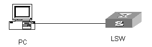
Figure 6-1 Network diagram for password control configuration
III. Configuration procedure
# Configure the system login password:
<H3C> system-view
System View: return to User View with Ctrl+Z.
[H3C] local-user test
[H3C-luser-test] password
Password:**********
confirm:**********
# Change the system login password to 0123456789:
[H3C-luser-test] password
Password:**********
Confirm :**********
Updating password-file ,please waiting ...
# Enable password aging:
[H3C] password-control aging enable
Password aging enabled for all users. Default: 90 days.
# Enable limitation of the minimum password length:
[H3C] password-control length enable
Password minimum length enabled for all users. Default: 10 characters.
# Enable history password recording:
[H3C] password-control history enable
Password history enabled for all users.
# Set the aging time of super passwords to 10 days:
[H3C] password-control super aging 10
# Display the password control information of all users:
[H3C] display password-control
Global password settings for all users:
Password aging: Enabled(90 days)
Password length: Enabled(10 Characters)
Password history: Enabled(Max history records:4)
Password alert-before-expire : 7 days
Password authentication-timeout : 60 seconds
Password attempt times : 3 times
Password attempt-failed action : Lock for 120 minutes
# Display the user names and the corresponding IP addresses added to the blacklist because of password attempt failure:
[H3C] display password-control blacklist
USERNAME IP
The number of users in blacklist is :0
# Delete the history password records of all users:
<H3C> reset password-control history-record
Are you sure to delete all the history record?[Y/N]
If you type "Y", the system will delete the history records of all users and gives the following prompt:
Updating the password file, please wait...
All historical passwords have been cleared.