- Table of Contents
-
- H3C S9500 Series Routing Switches Operation Manual-(V1.01)
- 00-1Cover
- 01-Getting Started Operation
- 02-Port Operation
- 03-VLAN-QinQ Operation
- 04-Network Protocol Operation
- 05-Routing Protocol Operation
- 06-Multicast Protocol Operation
- 07-QACL Operation
- 08-MPLS Operation
- 09-STP Operation
- 10-Security Operation
- 11-Reliability Operation
- 12-System Management Operation
- 13-PoE Operation
- 14-NAT-URPF-VPLS Operation
- 15-Integrated Management Operation
- 16-Appendix
- Related Documents
-
| Title | Size | Download |
|---|---|---|
| 09-STP Operation | 350 KB |
Table of Contents
Chapter 1 MSTP Region-configuration
1.1.3 MSTP Implementation on the Switch
1.2.1 Configuring the MST Region for a Switch
1.2.2 Specifying the Switch as a Primary or a Secondary Root bridge
1.2.3 Configuring the MSTP Running Mode
1.2.4 Configuring the Bridge Priority for a Switch.
1.2.5 Configuring the Max Hops in an MST Region.
1.2.6 Configuring the Switching Network Diameter
1.2.7 Configuring the Time Parameters of a Switch
1.2.8 Setting the Timeout Factor of a Specific Bridge
1.2.9 Configuring the Max Transmission Speed on a Port
1.2.10 Configuring a Port as an Edge Port or Non-edge Port
1.2.11 Configuring the Path Cost of a Port
1.2.12 Three Standards for Calculating STP Path Cost on an STP Port
1.2.13 Configuring the Priority of a Port
1.2.14 Configuring the Port (Not) to Connect with the Point-to-Point Link
1.2.15 Configuring the mCheck Variable of a Port
1.2.16 Configuring the Switch Protection Function
1.2.17 Enabling/Disabling MSTP on the Device
1.2.18 Enabling/Disabling MSTP on a Port
1.2.19 Disabling BPDU Packets from Flooding in the Default VLANs
1.3 Displaying and Debugging MSTP
1.4 Typical MSTP Configuration Example.
Chapter 2 Digest Snooping Configuration
2.1 Introduction to Digest Snooping
2.2 Digest Snooping Configuration
2.2.3 Digest Snooping Configuration Example.
Chapter 3 BPDU Tunnel Configuration
3.2.1 Enabling/disabling BPDU Tunnel
3.2.2 Enabling/disabling VLAN VPN on Ethernet port
3.3 BPDU Tunnel Configuration Example.
Chapter 1 MSTP Region-configuration
1.1 Introduction to MSTP
MSTP stands for Multiple Spanning Tree Protocol, which is compatible with Spanning Tree Protocol (STP) and Rapid Spanning Tree Protocol (RSTP).
STP is not fast in state transition. Even on a point-to-point link or an edge port, it has to take an interval twice as long as forward delay before the port transits to the forwarding state.
RSTP converges fast, but has the following drawback like STP: all the network bridges in a LAN share one spanning tree and the redundant links cannot be blocked based on VLANs. Packets of all VLANs are forwarded along one spanning tree.
MSTP makes up for the drawback of STP and RSTP. It not only converges fast, but also allows the traffic of different VLANs to be distributed along their respective paths, which provides a better load-balance mechanism for the redundant links.
MSTP keeps a VLAN mapping table to associate VLANs with their spanning trees. Using MSTP, you can divide one switching network into multiple regions, each of which can have multiple spanning trees with each one independent of others. MSTP prunes the ring network into a loopfree tree to avoid the generation of loops and infinite circulations. It also provides multiple redundant paths for data forwarding to implement the load-balance mechanism of the VLAN data.
1.1.1 MSTP Concepts
There are 4 MST regions in Figure 1-1. Each region consists of four switches, all of which run MSTP. The following introduces the concept of MSTP with the help of this figure.
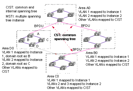
Figure 1-1 Basic MSTP concepts
I. MST region
Multiple Spanning Tree Regions: A multiple spanning tree region contains several switches and the network segments between them. These MSTP switches share the same region name, VLAN-spanning tree mapping configuration, and MSTP revision level configuration, and are connected directly. There can be several MST regions on a switching network. You can group several switches into a MST region, using MSTP configuration commands. For example, in Figure 1-1, the four switches in MST region A0 are configured with the same region name, the same VLAN mapping table (VLAN1 is mapped to instance 1, VLAN 2 is mapped to instance 2, other VLANs is mapped to instance CIST), and the same revision level (not indicated in Figure 1-1).
II. VLAN mapping table
The VLAN mapping table is an attribute of MST region. It is used for describing the mapping relationship of VLANs and spanning tree instances (STIs). For example, in the VLAN mapping table of MST region A0 in Figure 1-1, VLAN1 is mapped to instance 1, VLAN 2 is mapped to instance 2, other VLANs is mapped to CIST.
In the same region, the mapping relationship of VLANs and STIs must be consistent on all the switches in this region. Otherwise, VLAN and STI are not in the same region.
III. IST
Internal Spanning Tree (IST): a spanning tree in a MSTP region. The IST and the Common Spanning Tree (CST), together make up a Common and Internal Spanning Tree (CIST) for the entire switching network. The IST in a MST region is a fragment of the CIST. For example, every MST region in Figure 1-1 has an IST, which is a fragment of CIST.
IV. CST
Common Spanning Tree (CST): a LAN has only one CST. CST connects the spanning trees of all MST regions. Regard every MST region as a “switch”, and the CST is generated by the computing of “switches” through STP/RSTP. For example, the red line in Figure 1-1 indicates the CST.
V. CIST
Common and Internal Spanning Tree (CIST): A single spanning tree made up of ISTs and CST. It connects all switches in a switching network. CIST of Figure 1-1 is composed of ISTs in all MST regions and the CST.
VI. MSTI
Multiple Spanning Tree Instance (MSTI): multiple spanning trees can be generated with MSTP in an MST region and independent of one another. Such a spanning tree is called an MSTI. As shown is Figure 1-1, every MST region have many STIs. Each STI corresponds to a VLAN and is called a MSTI.
VII. Region root
The region root refers to the root of the IST and MSTI of the MST region. The spanning trees in an MST region have different topology and their region roots may also be different. For example, the region root of the STI 1 is the switch B and that of the STI 2 is the switch C, as shown in Figure 1-1.
VIII. Common Root Bridge
The Common Root Bridge refers to the root bridge of CIST. For example, the common root bridge is a certain switch in A0, as shown in Figure 1-1.
IX. Edge port
The edge port refers to the port located at the MST region edge, connecting different MST regions, MST region and STP region, or MST region and RSTP region. For MSTP calculation, the edge port shall take the same role on MSTI and CIST instance. For example, as shown in Figure 1-1, if a switch in region A0 connects to the first port on a switch in region D0, and the common root bridge of the whole switching network is in A0, then this first port is an edge port of region D0.
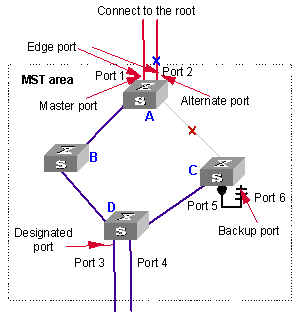
X. Port role
In the process of MSTP calculation, a port can serve as a designated port, root port, master port, alternate port, or backup port.
l The root port is the one through which the data are forwarded to the root.
l The designated port is the one through which the data are forwarded to the downstream network segment or switch.
l Master port is the port connecting the entire region to the Common Root Bridge and located on the shortest path between them.
l An alternate port is a backup of the mater port, and also a backup port of a root port in the region. As a backup of the mater port, an alternate port will become a new master port after a master port is blocked.
l If two ports of a switch are connected, there must be a loop. In this case, the switch blocks one of them. The blocked one is called a backup port.
A port can play different roles in different spanning tree instances.
The following figure illustrates the earlier-mentioned concepts for your better understanding. In this figure, the switch A, B, C, and D make up a MST region. Port 1 and 2 on switch A connects to the common root bridge; port 5 and 6 on switch C forms a loop; port 3 and 4 on switch D connects to other MST regions in the downstream direction.
XI. TC packet
Topology change (TC) means the structure of the MSTP spanning tree changes due to some bridge change or some port change on the network. In versatile routing platform (Comware) implementation, when a port state changes from discarding to forwarding, it means TC occurs.
The following section describes two kinds of STP packets:
1) MSTP BPDU packet
MSTP modules communicate with each other among bridges by MSTP BPDU packets. The following figure shows the MSTP BPDU packet format:
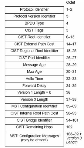
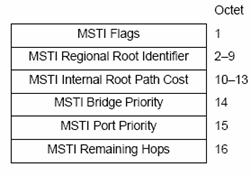
Figure 1-4 MSTI information format of the last part in BPDU packets
Besides field root bridge priority, root path cost, local bridge priority and port priority, the field flags which takes one byte in an instance is also used for role selection. The following figure describes the meaning of its eight bits:
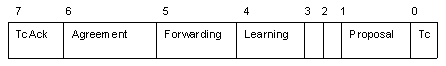
Figure 1-5 Meaning of 1-byte Flags in BPDU packets
The second and third bits together indicate MSTP port role.
2) TC packet
A TC packet is also an MSTP BPDU packet, but the lowest bit of its flags field is set to 1, which endows the TC packet with special meaning. So the TC packet has its special meaning. After receiving or detecting TC packets, a port will broadcast TC packets to tell the whole network the changed topology information at the fastest speed.
1.1.2 MSTP Principles
MSTP divides the entire Layer 2 network into several MST regions and calculates and generates CST for them. Multiple spanning trees are generated in a region and each of them is called an MSTI. The instance 0 is called IST, and others are called MSTI. Similar to RSTP, MSTP also use configuration messages to calculate and generate spanning trees, the difference is that it is the MSTP configuration information on the switches that is carried in the configuration messages.
I. CIST calculation
The CIST root is the highest-priority switch elected from the switches on the entire network through comparing their configuration BPDUs. MSTP calculates and generates IST in each MST region; at the same time it regards each MST region as a single "switch" and then calculates and generates the CST between the regions. The CST and ISTs together make up the CIST which connects all the switches in the whole switching network.
II. MSTI calculation
Inside an MST region, MSTP generates different MSTIs for different VLANs according to the association between VLAN and the spanning tree. The calculation process of MSTI is like that of RSTP.
The following introduces the calculation process of one MSTI.
The fundamental of STP is that the switches exchange a special kind of protocol packet (which is called configuration Bridge Protocol Data Units, or BPDU, in IEEE 802.1D) to decide the topology of the network. The configuration BPDU contains the information enough to ensure the switches to compute the spanning tree.
Figure 1-6 shows the Designated bridge and designated port.
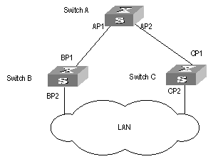
Figure 1-6 Designated bridge and designated port
For a switch, the designated bridge is a switch in charge of forwarding BPDU to the local switch via a port called the designated port accordingly. For a LAN, the designated bridge is a switch that is in charge of forwarding BPDU to the network segment via a port called the designated port accordingly. As illustrated in the Figure 1-6, Switch A forwards data to Switch B via the port AP1. To Switch B, the designated bridge is Switch A and the designated port is AP1. In the figure, Switch B and Switch C are connected to the LAN and Switch B forwards BPDU to LAN. So the designated bridge of LAN is Switch B and the designated port is BP2.
l The specific calculation process of STP algorithm.
The following example illustrates the calculation process of STP.
Figure 1-7 illustrates the practical network.
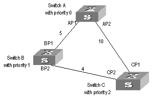
Figure 1-7 Ethernet switch networking
To facilitate the descriptions, only the first four parts of the configuration BPDU are described in the example. They are root ID (expressed as Ethernet switch priority), path cost to the root, designated bridge ID (expressed as Ethernet switch priority) and the designated port ID (expressed as the port number). As illustrated Figure 1-7, the priorities of Switch A, B and C are 0, 1 and 2 and the path costs of their links are 5, 10 and 4 respectively.
1) Initial state
When initialized, each port of the switches generates the configuration BPDU taking itself as the root with a root path cost as 0, designated bridge IDs as their own switch IDs and the designated ports as their ports.
Switch A:
Configuration BPDU of AP1: {0, 0, 0, AP1}
Configuration BPDU of AP2: {0, 0, 0, AP2}
Switch B:
Configuration BPDU of BP1: {1, 0, 1, BP1}
Configuration BPDU of BP2: {1, 0, 1, BP2}
Switch C:
Configuration BPDU of CP2: {2, 0, 2, CP2}
Configuration BPDU of CP1: {2, 0, 2, CP1}
2) Select the optimum configuration BPDU
Every switch transmits its configuration BPDU to others. When a port receives a configuration BPDU with a lower priority than that of its own, the switch discards the message and keep the local BPDU unchanged. When the port receives a higher-priority configuration BPDU, the switch uses the content in the received configuration BPDU to change the content of the local BPDU of this port. Then the switch compare the configuration BPDU of this port to those of other ports on it to elect the optimum configuration BPDU.
The comparison rules are:
l The configuration BPDU with a smaller root ID has a higher priority.
l If the root IDs are the same, perform the comparison based on root path costs. The cost comparison is as follows: the path cost to the root recorded in the configuration BPDU plus the corresponding path cost of the local port is set as S, the configuration BPDU with a smaller S has a higher priority.
l If the costs of path to the root are also the same, compare in sequence the designated bridge ID, designated port ID and the ID of the port via which the configuration BPDU was received.
For the convenience of expression, this example supposes that the optimum configuration BPDU can be elected just by the comparison of root IDs.
3) Determine the root and designated ports, and update the configuration BPDU of designated ports.
The port receiving the optimum configuration BPDU is designated to be the root port, whose configuration BPDU remains unchanged. Switch calculates a designated port BPDU for every port: substituting the root ID with the root ID in the configuration BPDU of the root port, the cost of path to root with the value made by the root path cost plus the path cost corresponding to the root port, the designated bridge ID with the local switch ID and the designated port ID with the local port ID.
Switch compares the calculated BPDU with the BPDU of corresponding port. If the BPDU of corresponding port is better, the port is blocked, and the BPDU of the port remains unchanged. The port will not forward data and only receive but not send BPDU. If the calculated BPDU is better, the port will be the designated port, and the port BPDU will be modified by the calculated BPDU and sent out regularly.
The comparison process of each switch is as follows.
Switch A:
AP1 receives the configuration BPDU from Switch B and finds out that the local configuration BPDU priority is higher than that of the received one, so it discards the received configuration BPDU. The configuration BPDU is processed on the AP2 in a similar way. Thus Switch A finds itself the root and designated bridge in the configuration BPDU of every port. It regards itself as the root, retains the configuration BPDU of each port and transmits configuration BPDU to others regularly thereafter. By now, the configuration BPDUs of the two ports are as follows:
Configuration BPDU of AP1: {0, 0, 0, AP1}.
Configuration BPDU of AP2: {0, 0, 0, AP2}.
Switch B:
BP1 receives the configuration BPDU from Switch A and finds that the received BPDU has a higher priority than the local one, so it updates its configuration BPDU.
BP2 receives the configuration BPDU from Switch C and finds that the local BPDU priority is higher than that of the received one, so it discards the received BPDU.
By now, the configuration BPDUs of each port are as follows: Configuration BPDU of BP1: {0, 0, 0, AP1}, Configuration BPDU of BP2: {1, 0, 1, BP2}.
Switch B compares the configuration BPDUs of the ports and selects the BP1 BPDU as the optimum one because the current configuration BPDU {0, 5, 0, AP1} of BP1 has a higher priority than the configuration BPDU {1, 0, 1, BP2} of BP2. Thus BP1 is elected as the root port and the configuration BPDUs of Switch B ports are updated as follows.
The configuration BPDU of the root port BP1 retains as {0, 5, 0, AP1}. BP2 updates root ID with that in the optimum configuration BPDU, the path cost to root with 5, sets the designated bridge as the local switch ID and the designated port ID as the local port ID. Thus, the configuration BPDU becomes {0, 5, 1, BP2}.
Then, all the designated ports of Switch B transmit the configuration BPDUs regularly.
Switch C:
CP2 receives from the BP2 of Switch B the configuration BPDU {1, 0, 1, BP2} that has not been updated and then the updating process is launched. The configuration BPDU is updated as {1, 0, 1, BP2}.
CP1 receives the configuration BPDU {0, 0, 0, AP2} from Switch A and Switch C launches the updating. The configuration BPDU is updated as {0, 0, 0, AP2}.
Now, the configuration BPDU of CP1 is {0, 10, 0, AP2}, which has a higher priority than that of CP2.By comparison, CP1 configuration BPDU is elected as the optimum one. The CP1 is thus specified as the root port without modifying its configuration BPDU. However, CP2 will be blocked and its BPDU also remains unchanged, but it will not receive the data (excluding the STP packets) forwarded from Switch B until spanning tree calculation is launched again by some new events. For example, the link from Switch B to Switch C is down or the port receives any better configuration BPDU.
CP2 will receive the updated configuration BPDU, {0, 5, 1, BP2}, from Switch B. Since this configuration BPDU is better then the old one, the old BPDU will be updated to {0, 5, 1, BP2}.
Meanwhile, CP1 receives the configuration BPDU from Switch A but its configuration BPDU is not updated and retain {0, 10, 0, AP2}.
By comparison, {0, 9, 1, BP2}, the configuration BPDU of CP2, is elected as the optimum one. Thus, CP2 is elected as the root port, whose BPDU will not change, while CP1 is blocked, its BPDU is retained, and will not receive the data forwarded from Switch A until spanning tree calculation is triggered again by some changes. For example, the link from Switch B to Switch C is down or the port receives any better configuration BPDU
Thus, the spanning tree is stabilized. The tree with the root bridge A is illustrated in the Figure 1-8.
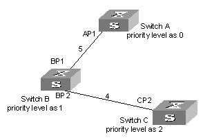
Figure 1-8 The final stabilized spanning tree
To facilitate the descriptions, the description of the example is simplified. For example, the root ID and the Designated bridge ID in actual calculation should comprise both switch priority and switch MAC address. Designated port ID should comprise port priority and port ID. In the updating process of a configuration BPDU, other configuration BPDUs besides the first four items will make modifications according to certain rules. The basic calculation process is described below:
In addition, with identical priority, the path cost of an aggregation port is smaller than that of a non-aggregation port. Therefore, under identical root ID, path cost value and designated switch ID, the switch will generally select the aggregation port as the root port.
l Configuration BPDU forwarding mechanism in STP:
Upon the initiation of the network, all the switches regard themselves as the roots. The designated ports send the configuration BPDUs of local ports at a regular interval of HelloTime. If it is the root port that receives the configuration BPDU, the switch will enable a timer to time the configuration BPDU as well as increase MessageAge carried in the configuration BPDU by certain rules. If a path goes wrong, the root port on this path will not receive configuration BPDUs any more and the old configuration BPDUs will be discarded due to timeout. Hence, recalculation of the spanning tree will be initiated to generate a new path to replace the failed one and thus restore the network connectivity.
However, the new configuration BPDU as now recalculated will not be propagated throughout the network right away, so the old root ports and designated ports that have not detected the topology change will still forward the data through the old path. If the new root port and designated port begin to forward data immediately after they are elected, an occasional loop may still occur. In STP, a transitional state mechanism is thus adopted to ensure the new configuration BPDU has been propagated throughout the network before the root port and designated port begin to send data again. That is, the root port and designated port should undergo a transitional state for a period of Forward Delay before they enter the forwarding state.
And thus, the packets of a VLAN will be forwarded along the following path: in the MST region, the packets will be forwarded along the corresponding MSTI; among the regions, the packets will be forwarded along the CST.
1.1.3 MSTP Implementation on the Switch
MSTP is compatible with STP and RSTP. The MSTP switch can recognize both the STP and RSTP packets and calculate the spanning tree with them. Besides the basic MSTP functions, H3C Ethernet Switch Series also provide some features easy to manage from users’ point of view. These features include root bridge hold, secondary root bridge, ROOT protection, BPDU protection, loop protection, hot swapping of the interface boards, master/slave switchover, and so on. Note that the spanning tree needs to be calculated again when a master/slave switchover occurs.
1.2 Configuring MSTP
MSTP configuration includes:
l Configuring the MST Region for a Switch
l Specifying the Switch as a Primary or a Secondary Root bridge
l Configuring the MSTP Running Mode
l Configuring the Bridge Priority for a Switch
l Configuring the Max Hops in an MST Region
l Configuring the Switching Network Diameter
l Configuring the Time Parameters of a Switch
l Setting the Timeout Factor of a Specific Bridge
l Configuring the Max Transmission Speed on a Port
l Configuring a Port as an Edge Port or Non-edge Port
l Configuring the Path Cost of a Port
l Three Standards for Calculating STP Path Cost on an STP Port
l Configuring the Priority of a Port
l Configuring the Port (Not) to Connect with the Point-to-Point Link
l Configuring the mCheck Variable of a Port
l Configuring the Switch Protection Function
l Enabling/Disabling MSTP on the Device
l Enabling/Disabling MSTP on a Port
l Disabling BPDU Packets from Flooding in the Default VLANs.
Only after MSTP is enabled on the device will other configurations take effect. Before enabling MSTP, you can configure the related parameters of the device and Ethernet ports, which will take effect upon enabling MSTP and stay effective even after resetting MSTP. The check region-configuration command can display the region parameters that have not yet taken effect. The display current-configuration command shows the parameters configured before MSTP is enabled. For those configured after MSTP is enabled, you can use the related display commands. For detailed information, refer to the “Display and Debug MSTP” section.
& Note:
When GVRP and MSTP start on the switch simultaneously, GVRP packets will propagate along CIST which is a spanning tree instance. In this case, if you want to issue a certain VLAN through GVRP on the network, you should make sure that the VLAN is mapped to CIST when configuring the VLAN mapping table of MSTP.
CIST is spanning tree instance 0.
1.2.1 Configuring the MST Region for a Switch
Which MST region a switch belongs to is determined with the configurations of the region name, VLAN mapping table, and MSTP revision level. You can perform the following configurations to put a switch into an MST region.
I. Entering MST region view
Perform the following configuration in system view.
Table 1-1 Enter MST region view
|
Operation |
Command |
|
Enter MST region view (from system view) |
stp region-configuration |
|
Restore the default settings of MST region |
undo stp region-configuration |
II. Configuring parameters for the MST region
Perform the following configuration in MST region view.
Table 1-2 Configure the MST region for a switch
|
Operation |
Command |
|
Configure the MST region name |
region-name name |
|
Restore the default MST region name |
undo region-name |
|
Configure VLAN mapping table |
instance instance-id vlan vlan-list |
|
Restore the default VLAN mapping table |
undo instance instance-id [ vlan vlan-list ] |
|
Configure the MSTP revision level of MST region |
revision-level level |
|
Restore the MSTP revision level of MST region |
undo revision-level |
An MST region can contain up to 49 spanning tree instances, among which the Instance 0 is IST and the Instances 1 through 48 are MSTIs. Upon the completion of the above configurations, the current switch is put into a specified MST region. Note that two switches belong to the same MST region only if they have been configured with the same MST region name, STI-VLAN mapping tables of an MST region, and the same MST region revision level.
Configuring the related parameters, especially the VLAN mapping table, of the MST region, will lead to the recalculation of spanning tree and network topology flapping. To bate such flapping, MSTP triggers to recalculate the spanning tree according to the configurations only if one of the following conditions is met:
l A user manually activates the configured parameters related to the MST region, using the active region-configuration command.
l A user enables MSTP using the stp enable command.
By default, the MST region name is the switch MAC address, all the VLANs in the MST region are mapped to the STI 0, and the MSTP region revision level is 0. You can restore the default settings of MST region, using the undo stp region-configuration command in system view.
III. Configuring the mapping relationship between a VLAN list and a Spanning Tree Instance
MSTP describes the mapping relationship between VLAN and Spanning Tree instances through the VLAN mapping table. You can use this command to configure the VLAN mapping table: each VLAN can be allocated to different Spanning Tree instances according to your configuration.
You cannot map one VLAN to different instances. When you map a mapped VLAN to a different MSTI, the previous mapping relationship will be automatically cancelled.
The vlan-mapping modulo modulo command can specify a VLAN to each Spanning Tree instance quickly. This command maps a VLAN to the Spanning Tree instance whose ID is (VLAN ID-1) %modulo+1. (Note: (VLAN ID-1) %modulo is the modulo operation for (VLAN ID-1). If the modulo operation is based on 16, VLAN 1 is mapped to MSTI 1, VLAN 2 is mapped to MSTI 2...VLAN 16 is mapped to MSTI 16, VLAN 17 is mapped to VLAN 17, and so on.)
Perform the following configurations in MST region view.
Table 1-3 Map all the VLAN lists to the specific Spanning Tree instances
|
Operation |
Command |
|
Map all the VLAN lists to the specific Spanning Tree instances uniformly through the modulo operation. |
vlan-mapping modulo modulo |
|
Restore the default mapping relationship between VLAN lists and Spanning Tree instances. |
undo vlan-mapping modulo |
By default, all the VLAN lists are mapped to CIST, namely, Instance 0.
IV. Activating the MST region configuration, and exit the MST region view
Perform the following configuration in MST region view.
Table 1-4 Activate the MST region configuration and exit the MST region view
|
Operation |
Command |
|
Show the configuration information of the MST region under revision |
check region-configuration |
|
Manually activate the MST region configuration |
active region-configuration |
|
Exit MST region view |
quit |
1.2.2 Specifying the Switch as a Primary or a Secondary Root bridge
MSTP can determine the spanning tree root through calculation. You can also specify the current switch as the root, using the command provided by the switch.
You can use the following commands to specify the current switch as the primary or secondary root of the spanning tree.
Perform the following configuration in system view.
Table 1-5 Specify the switch as a primary or a secondary root bridge
|
Operation |
Command |
|
Specify the current switch as the primary root bridge of the specified spanning tree |
stp [ instance instance-id ] root primary [ bridge-diameter bridgenum ] [ hello-time centi-senconds ] |
|
Specify the current switch as the secondary root bridge of the specified spanning tree |
stp [ instance instance-id ] root secondary [ bridge-diameter bridgenum ] [ hello-time centi-senconds ] |
|
Specify current switch not to be the primary or secondary root |
undo stp [ instance instance-id ] root |
After a switch is configured as the primary root bridge or the secondary root bridge, users cannot modify the bridge priority of the switch.
You can configure the current switch as the primary or secondary root bridge of the STI (specified by the instance instance-id parameter). If the instance-id takes 0, the current switch is specified as the primary or secondary root bridge of the CIST.
The root types of a switch in different STIs are independent of one another. The switch can be a primary or secondary root of any STI. However, it cannot serve as both the primary and secondary roots of one STI.
If the primary root is down or powered off, the secondary root will take its place, unless you configure a new primary root. Of two or more configured secondary root bridges, MSTP selects the one with the smallest MAC address to take the place of the failed primary root.
When configuring the primary and secondary switches, you can also configure the network diameter and hello time of the specified switching network. For detailed information, refer to the configuration tasks “Configure switching network diameter” and “Configure the Hello Time of the switch”.
& Note:
You can configure the current switch as the root of several STIs. However, it is not necessary to specify two or more roots for an STI. In other words, do not specify the root for an STI on two or more switches.
You can configure more than one secondary root for a spanning tree through specifying the secondary STI root on two or more switches.
Generally, you are recommended to designate one primary root and more than one secondary root for a spanning tree.
By default, a switch is neither the primary root nor the secondary root of the spanning tree.
1.2.3 Configuring the MSTP Running Mode
MSTP and RSTP are compatible and they can recognize the packets of each other. However, STP cannot recognize MSTP packets. To implement the compatibility, MSTP provides two operation modes, STP-compatible mode and MSTP mode. In STP-compatible mode, the switch sends STP packets via every port. In MSTP mode, the switch ports send MSTP or STP packets (when connected to the STP switch) and the switch provides multiple spanning tree function.
You can use the following command to configure MSTP running mode. MSTP can intercommunicate with STP. If there is a STP switch in the switching network, you may use the command to configure the current MSTP to run in STP-compatible mode. Otherwise, configure it to run in MSTP mode.
Perform the following configuration in system view.
Table 1-6 Configure the MSTP running mode
|
Operation |
Command |
|
Configure MSTP to run in STP-compatible mode |
stp mode stp |
|
Configure MSTP to run in MSTP mode |
stp mode mstp |
|
Restore the default MSTP running mode |
undo stp mode |
Generally, if there is a STP switch on the switching network, the port connected to it will automatically transit from MSTP mode to STP-compatible mode. But the port cannot automatically transit back to MSTP mode after the STP switch is removed. In this case, you can execute the stp mcheck command to restore the MSTP mode.
By default, the switch runs in MSTP mode.
1.2.4 Configuring the Bridge Priority for a Switch
Whether a switch can be elected as the spanning tree root depends on its Bridge priority. The switch configured with a smaller Bridge priority is more likely to become the root. An MSTP switch may have different priorities in different STIs.
You can use the following command to configure the Bridge priorities of the Designated bridge in different STIs.
Perform the following configuration in system view.
Table 1-7 Configure the Bridge priority for a switch
|
Operation |
Command |
|
Configure the Bridge priority of the Designated bridge |
stp [ instance instance-id ] priority priority |
|
Restore the default Bridge priority of the Designated bridge |
undo stp [ instance instance-id ] priority |
When configuring the switch priority with the instance instance-id parameter as 0, you are configuring the CIST priority of the switch.
![]() Caution:
Caution:
In the process of spanning tree root election, of two or more switches with the same Bridge priorities, the one has a smaller MAC address is elected as the root.
By default, the switch Bridge priority is 32768.
1.2.5 Configuring the Max Hops in an MST Region
The scale of MST region is limited by the max hops in an MST region, which is configured on the region root. As the BPDU travels from the spanning tree root, each time when it is forwarded by a switch, the max hops is reduced by 1. The switch discards the configuration BPDU with 0 hops left. This makes it impossible for the switch beyond the max hops to take part in the spanning tree calculation, thereby limiting the scale of the MST region.
You can use the following command to configure the max hops in an MST region.
Perform the following configuration in system view.
Table 1-8 Configure the max hops in an MST region
|
Operation |
Command |
|
Configure the max hops in an MST region |
stp max-hops hop |
|
Restore the default max hops in an MST region |
undo stp max-hops |
The more the hops in an MST region, the larger the scale of the region. Only the max hops configured on the region root can limit the scale of MST region. Other switches in the MST region also apply the configurations on the region root, even if they have been configured with max hops.
By default, the max hop of an MST is 20.
1.2.6 Configuring the Switching Network Diameter
Any two hosts on the switching network are connected with a specific path carried by a series of switches. Among these paths, the one passing more switches than all others is the network diameter, expressed as the number of passed switches.
You can use the following command to configure the diameter of the switching network.
Perform the following configuration in system view.
Table 1-9 Configure the switching network diameter
|
Operation |
Command |
|
Configure the switching network diameter |
stp bridge-diameter bridgenum |
|
Restore the default switching network diameter |
undo stp bridge-diameter |
The network diameter is the parameter specifying the network scale. The larger the diameter is, the lager the scale of the network is.
When a user configures the network diameter on a switch, MSTP automatically calculates and sets the Hello Time, Forward-Delay and Max Age time of the switch to the desirable values.
Setting the network diameter takes effect on CIST only, but has no effect on MSTI.
By default, the network diameter is 7 and the three corresponding timers take the default values.
& Note:
The stp bridge-diameter command configures the switching network diameter and determines the three MSTP time parameters (Hello Time, Forward Delay, and Max Age) accordingly.
1.2.7 Configuring the Time Parameters of a Switch
The switch has three time parameters, Forward Delay, Hello Time, and Max Age.
Forward Delay is the switch state transition mechanism. The spanning tree will be recalculated upon link faults and its structure will change accordingly. However, the configuration BPDU recalculated cannot be immediately propagated throughout the network. The temporary loops may occur if the new root port and designated port forward data right after being elected. Therefore the protocol adopts a state transition mechanism. It takes a Forward Delay interval for the root port and designated port to transit from the learning state to forwarding state. The Forward Delay guarantees a period of time during which the new configuration BPDU can be propagated throughout the network.
The switch sends Hello packet periodically at an interval specified by Hello Time to check if there is any link fault.
Max Age specifies when the configuration BPDU will expire. The switch will discard the expired configuration BPDU.
You can use the following command to configure the time parameters for the switch.
Perform the following configuration in system view.
Table 1-10 Configure the time parameters of a switch
|
Operation |
Command |
|
Configure Forward Delay on the switch |
stp timer forward-delay centi-seconds |
|
Restore the default Forward Delay of the switch |
undo stp timer forward-delay |
|
Configure Hello Time on the switch |
stp timer hello centi-seconds |
|
Restore the default Hello Time on the switch |
undo stp timer hello |
|
Configure Max Age on the switch |
stp timer max-age centi-seconds |
|
Restore the default Max Age on the switch |
undo stp timer max-age |
Every switch on the switching network adopts the values of the time parameters configured on the root bridge of the CIST.
![]() Caution:
Caution:
The Forward Delay configured on a switch depends on the switching network diameter. Generally, the Forward Delay is supposed to be longer when the network diameter is longer. Note that too short a Forward Delay may redistribute some redundant routes temporarily, while too long a Forward Delay may prolong the network connection resuming. The default value is recommended.
A suitable Hello Time ensures the switch to detect the link fault on the network but occupy moderate network resources. The default value is recommended. If you set too long a Hello Time, when there is packet dropped over a link, the switch may consider it as a link fault and the network device will recalculate the spanning tree accordingly. However, for too short a Hello Time, the switch frequently sends configuration BPDU, which adds its burden and wastes the network resources.
Too short a Max Age may cause the network device frequently calculate the spanning tree and mistake the congestion as a link fault. However, if the Max Age is too long, the network device may not be able to discover the link fault and recalculate the spanning tree in time, which will weaken the auto-adaptation capacity of the network. The default value is recommended.
To avoid frequent network flapping, the values of Hello Time, Forward Delay and Max Age should guarantee the following formulas.
2 x (Forward-Delay – 1 second) >= Max Age
Max Age >= 2 x (Hello Time + 1 second)
You are recommended to use the stp bridge-diameter command to specify the network diameter and Hello Time of the switching network, and then MSTP will automatically calculate and give the rather desirable values.
By default, Forward Delay is 15 seconds, Hello Time is 2 seconds, and Max Age is 20 seconds.
1.2.8 Setting the Timeout Factor of a Specific Bridge
A switch transmits hello packet regularly to the adjacent bridges to check if there is link failure. Generally, if the switch does not receive the STP packets from the upstream switch for 3 times of hello time, the switch will decide the upstream switch is dead and will recalculate the topology of the network. Then, in a steady network, the recalculation may be caused when the upstream is busy. In this case, user can redefine the timeout interval to a longer time to avoid this kind of meaningless recalculation.
You can use the following command to set the multiple value of hello time of a specified bridge.
Perform the following configurations in system view.
Table 1-11 Setting the timeout factor of a specific switch
|
Operation |
Command |
|
Set the timeout factor of a specified switch |
stp timer-factor number |
|
Restore the default timeout factor |
undo stp timer-factor |
It is recommended to set 5, 6 or 7 as the timeout factor in the steady network.
By default, the timeout factor of the switch is 3.
1.2.9 Configuring the Max Transmission Speed on a Port
The max transmission speed on a port specifies how many MSTP packets will be transmitted via the port every Hello Time.
The max transmission speed on a port is limited by the physical state of the port and the network structure. You can configure it according to the network conditions.
You can configure the max transmission speed on a port in the following ways.
I. Configuration in system view
Perform the following configuration in system view.
Table 1-12 Configure the max transmission speed on a port
|
Operation |
Command |
|
Configure the max transmission speed on a port |
stp interface interface-list transmit-limit packetnum |
|
Restore the default max transmission speed on a port |
undo stp interface interface-list transmit-limit |
II. Configuration in Ethernet port view
Perform the following configuration in Ethernet port view.
Table 1-13 Configure the max transmission speed on a port
|
Operation |
Command |
|
Configure the max transmission speed on a port |
stp transmit-limit packetnum |
|
Restore the default max transmission speed on a port |
undo stp transmit-limit |
You can configure the max transmission speed on a port with either of the earlier-mentioned measures. For more about the commands, refer to the Command Manual.
This parameter only takes a relative value without units. If it is set too large, too many packets will be transmitted during every Hello Time and too many network resources will be occupied. The default value is recommended.
By default, the max transmission speed on every Ethernet port of the switch is 3.
1.2.10 Configuring a Port as an Edge Port or Non-edge Port
An edge port refers to the port not directly connected to any switch or indirectly connected to a switch over the connected network.
You can configure a port as an edge port or non-edge port in the following ways.
I. Configuration in system view
Perform the following configuration in system view.
Table 1-14 Configure a port as an edge port or a non-edge port
|
Operation |
Command |
|
Configure a port as an edge port. |
stp interface interface-list edged-port enable |
|
Configure a port as a non-edge port. |
stp interface interface-list edged-port disable |
|
Restore the default setting of the port as a non-edge port. |
undo stp interface interface-list edged-port |
II. Configuration in Ethernet port view
Perform the following configuration in Ethernet port view.
Table 1-15 Configure a port as an edge port or a non-edge port
|
Operation |
Command |
|
Configure a port as an edge port. |
stp edged-port enable |
|
Configure a port as a non-edge port. |
stp edged-port disable |
|
Restore the default setting of the port as a non-edge port. |
undo stp edged-port |
You can configure a port as an edge port or a non-edge port with either of the earlier-mentioned measures.
After configured as an edge port, the port can fast transit from blocking state to forwarding state without any delay. You can only set the port connecting with the terminal as an edge port. The configuration of this parameter takes effect on all the STIs. In other words, if a port is configured as an edge port or non-edge port, it is configured the same on all the STIs.
If BPDU protection is enabled on the switch, the edged port is disabled when it receives BPDU packets from the user. Only the network administrators can enable the port.
By default, all the Ethernet ports of the switch have been configured as non-edge ports.
& Note:
It is better to configure the port directly connected with the terminal as an edge port, and enable the BPDU function on the port. That is, to realize fast state-transition and prevent the switch from being attacked.
![]() Caution:
Caution:
If STP has been enabled on the equipment connected to the switch, do not configure the edged ports on the equipment. Otherwise the system will fail to delete MAC address entries and ARP address entries on the port.
1.2.11 Configuring the Path Cost of a Port
Path Cost is related to the speed of the link connected to the port. On the MSTP switch, a port can be configured with different path costs for different STIs. Thus the traffic from different VLANs can run over different physical links, thereby implementing the VLAN-based load-balancing.
You can configure the path cost of a port in the following ways.
I. Configuration in system view
Perform the following configuration in system view.
Table 1-16 Configure the path cost of a port
|
Operation |
Command |
|
Configure the path cost of a port. |
stp interface interface-list [ instance instance-id ] cost cost |
|
Restore the default path cost of a port. |
undo stp interface interface-list [ instance instance-id ] cost |
II. Configuration in Ethernet port view
Perform the following configuration in Ethernet port view.
Table 1-17 Configure the path cost of a port
|
Operation |
Command |
|
Configure the path cost of a port |
stp [ instance instance-id ] cost cost |
|
Restore the default path cost of a port. |
undo stp [ instance instance-id ] cost |
You can configure the path cost of a port with either of the earlier-mentioned measures. Upon the change of path cost of a port, MSTP will recalculate the port role and transit the state. When instance-id takes 0, it indicates to set the path cost on the CIST.
By default, MSTP is responsible for calculating the path cost of a port.
1.2.12 Three Standards for Calculating STP Path Cost on an STP Port
The H3C S9500 Series Routing Switches support DOT1T calculation , DOT1D-1998 calculation and legacy path cost calculation. By default, legacy standard is applied for S9500 series.
The port rate must be obtained first before calculating the path cost of a port as the path cost is associated with the port rate. The three standards use their own way to work out the port rate, based on which each standard calculates the path cost of the by certain algorithm.
I. DOT1T calculation standard
1) Calculating the rate
l Aggregation port
The rate of either a primary or a secondary port in an aggregation port group is the sum of the port rates in the group. If a port is down, the rate is 0.
l Non-aggregation port
The actual rate counts.
2) Calculating the path cost
l Full-duplex and non-aggregation port at a rate less than 1 GE
Path cost = [200,000,000 / (rate ´ 10)] – 1
l Other ports
Path cost = 200,000,000 / (rate ´ 10)
II. DOT1D-1998 calculation standard
1) Calculating the rate
l Aggregation port
If the port is up, the actual rate counts. If the port is down, the rate is determined by that of the port which goes up first in the aggregation group. If all the ports in the aggregation group are down, the rate of the aggregation port is 0.
l Non-aggregation port
The actual rate counts.
2) Calculating the path cost
Table 1-18 details the correspondence between the rate range and the path cost values of the ports.
Table 1-18 Correspondence between the rate range and the PATH cost values
|
Rate range |
PATH cost value |
|
[0, 10] |
99 (for full-duplex port) 95 (for aggregation port) 100 (default) |
|
(10, 100] |
18 (for full-duplex port) 15 (for aggregation port) 19 (default) |
|
(100,1000] |
3 (for aggregation port) 4 (default) |
|
(1000,10000] |
2 (for aggregation port) 1 (default) |
|
> 10000 |
1 |
III. Legacy calculation standard
1) Calculating the rate
l Aggregation port
The rate of the primary port in an aggregation group is determined by the sum of the port rates in this group. No calculation is performed for secondary port.
l Non-aggregation port
The actual rate counts, but the rate is 0 if the port is down.
2) Calculating the path cost
Table 1-19 details the correspondence between the rate range and the value range of the path cost of the ports.
Table 1-19 Correspondence between the rate range and PATH cost range
|
Rate range |
PATH cost range |
|
[0, 100] |
2200 to (20 ´ rate) |
|
(100,1000] |
220 to the integer of [(0.2 ´ rate)] |
|
(1000,10000] |
22 to the integer of [(0.002 ´ rate)] |
|
> 10000 |
1 |
You can specify the intended standard by using the following commands.
Perform the following configuration in system view.
Table 1-20 Specifying the standard to be followed in path cost calculation
|
Operation |
Command |
|
Specify the standard to be adopted when the switch calculates the default path cost for the connected link |
stp pathcost-standard { dot1d-1998 | dot1t legacy} |
|
Restore the default standard to be used |
undo stp pathcost-standard |
By default, the switch calculates the default path cost of a port by the legacy standard.
1.2.13 Configuring the Priority of a Port
For spanning tree calculation, the port priority is an importance factor to determine if a port can be elected as the root port. With other things being equal, the port with the highest priority will be elected as the root port. On the MSTP switch, a port can have different priorities in different STIs and plays different roles respectively. Thus the traffic from different VLANs can run over different physical links, thereby implementing the VLAN-based load-balancing.
You can configure the port priority in the following ways.
I. Configuration in system view
Perform the following configuration in system view.
Table 1-21 Configure the port priority
|
Operation |
Command |
|
Configure the port priority. |
stp interface interface-list instance instance-id port priority priority |
|
Restore the default port priority. |
undo stp interface interface-list instance instance-id port priority |
II. Configuration in Ethernet port view
Perform the following configuration in Ethernet port view.
Table 1-22 Configure the port priority
|
Operation |
Command |
|
Configure the port priority. |
stp [ instance instance-id ] port priority priority |
|
Restore the default port priority. |
undo stp [ instance instance-id ] port priority |
You can configure the port priority with either of the earlier-mentioned measures. Upon the change of port priority, MSTP will recalculate the port role and transit the state. Generally, a smaller value represents a higher priority. If all the Ethernet ports of a switch are configured with the same priority value, the priorities of the ports will be differentiated by the index number. The change of Ethernet port priority will lead to spanning tree recalculation. You can configure the port priority according to actual networking requirements.
By default, the priority of all the Ethernet ports is 128.
1.2.14 Configuring the Port (Not) to Connect with the Point-to-Point Link
The point-to-point link directly connects two switches.
You can configure the port (not) to connect with the point-to-point link in the following ways.
I. Configuration in system view
Perform the following configuration in system view.
Table 1-23 Configure the port (not) to connect with the point-to-point link
|
Operation |
Command |
|
Configure the port to connect with the point-to-point link. |
stp interface interface-list point-to-point force-true |
|
Configure the port not to connect with the point-to-point link. |
stp interface interface-list point-to-point force-false |
|
Configure MSTP to automatically detect if the port is directly connected with the point-to-point link. |
stp interface interface-list point-to-point auto |
|
Configure MSTP to automatically detect if the port is directly connected with the point-to-point link, as defaulted. |
undo stp interface interface-list point-to-point |
II. Configuration in Ethernet port view
Perform the following configuration in Ethernet port view.
Table 1-24 Configure the port (not) to connect with the point-to-point link
|
Operation |
Command |
|
Configure the port to connect with the point-to-point link. |
stp point-to-point force-true |
|
Configure the port not to connect with the point-to-point link. |
stp point-to-point force-false |
|
Configure MSTP to automatically detect if the port is directly connected with the point-to-point link. |
stp point-to-point auto |
|
Configure MSTP to automatically detect if the port is directly connected with the point-to-point link, as defaulted. |
undo stp point-to-point |
You can configure the port (not) to connect with the point-to-point link with either of the earlier-mentioned measures. For the ports connected with the point-to-point link, upon some port role conditions met, they can transit to forwarding state fast through transmitting synchronization packet, thereby reducing the unnecessary forwarding delay. If the parameter is configured as auto mode, MSTP will automatically detect if the current Ethernet port is connected with the point-to-point link.
& Note:
For a link aggregation, only the master port can be configured to connect with the point-to-point link. If a port in auto-negotiation mode operates in full-duplex mode upon negotiation, it can be configured to connect with the point-to-point link.
This configuration takes effect on the CIST and all the MSTIs. The settings of a port whether to connect the point-to-point link will be applied to all the STIs to which the port belongs. Note that a temporary loop may be redistributed if you configure a port that is not physically connected with the point-to-point link as connected to such a link by force.
By default, the parameter is configured as auto.
1.2.15 Configuring the mCheck Variable of a Port
The port of an MSTP switch operates in either STP-compatible or MSTP mode.
Suppose a port of an MSTP switch on a switching network is connected to an STP switch, the port will automatically transit to operate in STP-compatible mode. However, the port stays in STP-compatible mode and cannot automatically transit back to MSTP mode when the STP switch is removed. In this case, you can perform mCheck operation to transit the port to MSTP mode by force.
You can use the following measure to perform mCheck operation on a port.
I. Configuration in system view
Perform the following configuration in system view.
Table 1-25 Configure the mCheck variable of a port
|
Operation |
Command |
|
Perform mCheck operation on a port. |
stp interface interface-list mcheck |
& Note:
By default, MSTP runs in MSTP mode, which is compatible with RSTP and STP (This mode can recognize MSTP BPDU, STP config BPDU and RSTP config BPDU). However, the STP switch can only recognize config BPDU (STP BPDU) sent by the STP and RSTP bridges. After the switch running STP-compatible mode switches back to MSTP mode, it will not send MSTP BPDU if you do not execute the stp mcheck command. Therefore, the connected device still sends config BPDU (STP BPDU) to it, causing the same configuration exists in different regions and other problems. Remember to perform stp interface mcheck after modifying stp mode.
II. Configuration in Ethernet port view
Perform the following configuration in Ethernet port view.
Table 1-26 Configure the mCheck variable of a port
|
Operation |
Command |
|
Perform mCheck operation on a port. |
stp mcheck |
You can configure mCheck variable on a port with either of the earlier-mentioned measures. Note that the command can be used only if the switch runs MSTP. The command does not make any sense when the switch runs in STP-compatible mode.
1.2.16 Configuring the Switch Protection Function
An MSTP switch provides BPDU protection, Root protection functions, loop protection and TC-protection.
I. BPDU protection
For an access device, the access port is generally directly connected to the user terminal (for example, PC) or a file server, and the access port is set to an edge port to implement fast transition. When such a port receives BPDU packet, the system will automatically set it as a non-edge port and recalculate the spanning tree, which causes the network topology flapping. In normal cases, these ports will not receive STP BPDU. If someone forges BPDU to attack the switch, the network will flap. BPDU protection function is used against such network attacks.
II. Root protection
The primary and secondary root bridges of the spanning tree, especially those of ICST, shall be located in the same region. It is because the primary and secondary roots of CIST are generally placed in the core region with a high bandwidth in network design. In case of configuration error or malicious attack, the legal primary root may receive the BPDU with a higher priority and then loose its place, which causes network topology change errors. Due to the illegal change, the traffic supposed to travel over the high-speed link may be pulled to the low-speed link and congestion will occur on the network. Root protection function is used against such problems.
III. Loop protection
The root port and other blocked ports maintain their states according to the BPDUs send by uplink switch. Once the link is blocked or has trouble, then the ports cannot receive BPDUs and the switch will select root port again. In this case, the downstream switch selects the port role again. The downstream bridge port that cannot receive BGPUs becomes specific port and the blocked port is transferred to the forwarding state. As a result, a link loop is generated. The loop protection function can prohibit such loop.
& Note:
For the loop protection-enabled port, when the loop protection takes effect because the port cannot receive the BPDU sent by the upstream switches, if the port participates in STP calculation, all the instances of the port will be always set to be in discarding state regardless of the port role.
IV. TC-protection
As a general rule, the switch deletes the corresponding entries in the MAC address table and ARP table upon receiving TC-BPDU packets. Under malicious attacks of TC-BPDU packets, the switch shall receive a great number of TC-BPDU packets in a very short period. Too frequent delete operations shall consume huge switch resources and bring great risk to network stability.
When the protection from TC-BPDU packet attack is enabled, the switch just perform one delete operation in a specified period (generally, 15 seconds) after receiving TC-BPDU packets, as well as monitoring whether it receives TC-BPDU packets during this period. Even if it detects a TC-BPDU packet is received in a period shorter than the specified interval, the switch shall not run the delete operation till the specified interval is reached. This can avoid frequent delete operations on the MAC address table and ARP table.
You can use the following command to configure the protection functions of the switch.
Perform the following configuration in corresponding configuration modes.
Table 1-27 Configure the switch protection function
|
Operation |
Command |
|
Configure BPDU protection of the switch (from system view) |
stp bpdu-protection |
|
Restore the disabled BPDU protection state as defaulted (from system view) |
undo stp bpdu-protection |
|
Configure Root protection of the switch (from system view) |
stp interface interface-list root-protection |
|
Restore the disabled Root protection state as defaulted (from system view) |
undo stp interface interface-list root-protection |
|
Configure Root protection of the switch (from Ethernet port view) |
stp root-protection |
|
Restore the disabled Root protection state as defaulted (from Ethernet port view) |
undo stp root-protection |
|
Configure loop protection function of the switch (from Ethernet port view) |
stp loop-protection |
|
Restore the disabled loop protection state, as defaulted (from Ethernet port view) |
stp loop-protection |
|
Enable the loop protection function of the switch (from system view) |
stp interface interface-list loop-protection |
|
Restore the disabled loop protection state, as defaulted (from system view) |
undo stp interface interface-list loop-protection |
|
Configure TC protection of the switch (from system view) |
stp tc-protection enable |
|
Disable TC protection (from system view) |
stp tc-protection disable |
![]() Caution:
Caution:
If the equipment connected to the port of the switch cannot send STP packets to the switch, do not configure the loop-protection command. Otherwise, the port may be congested for a long time.
By default, only the protection from TC-BPDU packet attack is enabled on the switch. BPDU protection, Root protection and loop protection are disabled.
After configured with BPDU protection, the switch will disable the edge port through MSTP which receives a BPDU, and notify the network manager at same time. These ports can be resumed by the network manager only.
The port configured with Root protection only plays a role of designated port on every instance. Whenever such port receives a higher-priority BPDU, that is, it is about to turn into non-designated port, it will be set to listening state and not forward packets any more (as if the link to the port is disconnected). If the port has not received any higher-priority BPDU for a certain period of time thereafter, it will resume the normal state.
For one port, only one configuration can be effective among loop protection, Root protection and Edge port configuration at the same moment.
& Note:
The port configured with loop protection can only turn into discarding state on every instance. That such a port receives no configuration message for a long time indicates that it is about to change its state and role. Only the port role changes but the port discarding state remains unchanged, and no packets are forwarded. In this way, if the peer end cannot send BPDU packets due to error operation, and the port enters forwarding state directly for not receiving configuration message for a long time, no loop will be generated by enabling the loop protection.
By default, the switch does not enable BPDU protection or Root protection.
1.2.17 Enabling/Disabling MSTP on the Device
You can use the following command to enable MSTP on the device.
Perform the following configuration in system view.
Table 1-28 Enable/Disable MSTP on a device
|
Operation |
Command |
|
Enable MSTP on a device. |
stp enable |
|
Disable MSTP on a device. |
stp disable |
|
Restore the disable state of MSTP, as defaulted. |
undo stp |
Only if MSTP has been enabled on the device will other MSTP configurations take effect. If MSTP is disabled on the device, MSTP cannot be enabled on a port.
By default, MSTP is disabled.
1.2.18 Enabling/Disabling MSTP on a Port
You can use the following command to enable/disable MSTP on a port. You may disable MSTP on some Ethernet ports of a switch to spare them from spanning tree calculation. This is a measure to flexibly control MSTP operation and save the CPU resources of the switch.
MSTP can be enabled/disabled on a port through the following ways.
I. Configuration in system view
Perform the following configuration in system view.
Table 1-29 Enable/Disable MSTP on a port
|
Operation |
Command |
|
Enable MSTP on a port. |
stp interface interface-list enable |
|
Disable MSTP on a port. |
stp interface interface-list disable |
II. Configuration in Ethernet port view
Perform the following configuration in Ethernet port view.
Table 1-30 Enable/Disable MSTP on a port
|
Operation |
Command |
|
Enable MSTP on a port. |
stp enable |
|
Disable MSTP on a port. |
stp disable |
You can enable/disable MSTP on a port with either of the earlier-mentioned measures. Note that redundant route may be generated after MSTP is disabled.
By default, MSTP is enabled on all the ports after it is enabled on the device.
1.2.19 Disabling BPDU Packets from Flooding in the Default VLANs
If STP (spanning tree protocol) is not enabled, or if STP is disabled on a port though it is enabled globally, the BPDU packets through the STP-disabled port will be broadcast in the default VLAN, and these BPDU packets will affect the STP operation on other ports. The stp non-flooding command can discard the BPDU packets entering the STP-disabled port of the interface card, and thus prohibiting the BPDU packets from being broadcast in the VLAN.
Table 1-31 Disable BPDU packets from being broadcast on the default VLANs
|
Operation |
Command |
Description |
|
Enter system view |
system-view |
- |
|
Disable BPDU packets from being broadcast on STP-disabled ports |
stp non-flooding [ slot slotnum ] |
By default, BPDU packets are broadcast on STP-disabled ports. |
![]() Caution:
Caution:
It is recommended that after enabling STP, you disable the broadcasting function of BPDU to prevent the BPDU packets, which are received by ports that did not participate in the generation of spanning trees, from being forwarded to other ports, (which can cause errors during STP generations). Avoid using this function on VPLS-enabled LPUs so that STP packets can be forwarded in the VPLS network transparently
1.3 Displaying and Debugging MSTP
After the above configuration, execute the display command in any view to display the running of the MSTP configuration, and to verify the effect of the configuration. Execute the reset stp [ interface interface-list ] command in user view to clear the statistics of MSTP module. Execute the debugging command in user view to debug the MSTP module
Table 1-32 Display and debug MSTP
|
Operation |
Command |
|
Display the MSTP information about the current switch. |
display stp |
|
Display the configuration information about the current port and the switch. |
display stp [ instance instance-id ] [ interface interface-list | slot slot-num ] [ brief ] |
|
Display the current configurations of the specified service board. |
display stp slot number [ brief ] |
|
Display the configuration information about the region. |
display stp region-configuration |
|
Display TC statistics |
display stp [ instance instanceid ] tc { all | detected | received | sent } |
|
Clear the MSTP statistics information. |
reset stp [ interface interface-list ] |
|
Enable event debugging of MSTP for a specified port. |
debugging stp [ interface interface-list ] { lacp-key | packet | event } |
|
Disable debugging of MSTP for a specified port |
undo debugging stp [ interface interface-list ] { packet | event } |
|
Enable event debugging of MSTP |
debugging stp event |
|
Disable event debugging of MSTP |
undo debugging stp event |
|
Enable packet debugging of MSTP |
debugging stp packet |
|
Disable packet debugging of MSTP |
undo debugging stp packet |
|
Enable global debugging |
debugging stp all |
|
Disable global debugging |
undo debugging stp all |
|
Enable instance debugging of MSTP |
debugging stp instance instance-id |
|
Disable instance debugging of MSTP |
undo debugging stp instance instance-id |
|
Enable STP global error or event debugging |
debugging stp { global-error | global-event } |
|
Disable STP global error or event debugging |
undo debugging stp { global-error | global-event } |
|
Enable MD5 summary debugging of Lacp protocol |
debugging stp lacp-key |
|
Disable MD5 summary debugging of Lacp protocol |
undo debugging stp lacp-key |
|
Enable TC protection debugging |
debugging stp tc-protection |
|
Disable TC protection debugging |
undo debugging stp tc-protection |
1.4 Typical MSTP Configuration Example
I. Network requirements
MSTP provides different forwarding paths for packets of different VLANs. The configurations are as follows: all the switches in the network belong to the same MST region, packets of VLAN 10 travels along instance 1, packets of VLAN 30 travels along instance 3, packets of VLAN 40 travels along instance 4, and that of VLAN 20 travels along instance 0.
In the following network diagram, Switch A and Switch B are devices of the convergence layer, Switch C and Switch D are devices of the access layer. VLAN 10 and 30 function at the distribution and access layers, and VLAN 40 functions at the access layer only. So the root of instance 1 can be configured as Switch A, root of instance 3 can be Switch B, and root of instance 4 can be Switch C.
II. Network diagram
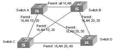
Figure 1-9 Network diagram for MSTP configuration
& Note:
The explanations on the above figure which goes like “permit: XXXX” means that packets of these VLANs are permitted to pass.
III. Configuration procedure
1) Configurations on Switch A
# MST region
<H3C> system-view
[H3C] stp region-configuration
[H3C-mst-region] region-name example
[H3C-mst-region] instance 1 vlan 10
[H3C-mst-region] instance 3 vlan 30
[H3C-mst-region] instance 4 vlan 40
[H3C-mst-region] revision-level 0
# Manually activate MST region configuration.
[H3C-mst-region] active region-configuration
# Specify Switch A as the root of instance 1
[H3C] stp instance 1 root primary
2) Configurations on Switch B
# MST region.
[H3C] stp region-configuration
[H3C-mst-region] region-name example
[H3C-mst-region] instance 1 vlan 10
[H3C-mst-region] instance 3 vlan 30
[H3C-mst-region] instance 4 vlan 40
[H3C-mst-region] revision-level 0
# Manually activate MST region configuration.
[H3C-mst-region] active region-configuration
# Specify Switch B as the root of instance 3
[H3C] stp instance 3 root primary
3) Configurations on Switch C
# MST region.
[H3C] stp region-configuration
[H3C-mst-region] region-name example
[H3C-mst-region] instance 1 vlan 10
[H3C-mst-region] instance 3 vlan 30
[H3C-mst-region] instance 4 vlan 40
[H3C-mst-region] revision-level 0
# Manually activate MST region configuration.
[H3C-mst-region] active region-configuration
# Specify Switch C as the root of instance 4.
[H3C] stp instance 4 root primary
4) Configurations on Switch D
# MST region
[H3C] stp region-configuration
[H3C-mst-region] region-name example
[H3C-mst-region] instance 1 vlan 10
[H3C-mst-region] instance 3 vlan 30
[H3C-mst-region] instance 4 vlan 40
[H3C-mst-region] revision-level 0
# Manually activate MST region configuration.
[H3C-mst-region] active region-configuration
Chapter 2 Digest Snooping Configuration
2.1 Introduction to Digest Snooping
According to IEEE 802.1s, two connected switches can communicate with each other through multiple spanning tree instances (MSTIs) in a multiple spanning tree protocol (MSTP) region only when they are configured with the same region settings. With MSTP employed, interconnected switches determine whether or not they are in the same region by checking the configuration IDs of the bridge protocol data units (BPDUs) between them. (A configuration ID comprises information such as region ID, configuration digest.)
As switches of some manufacturers come with some proprietary protocols concerning spanning trees employed, a switch of this type cannot communicate with other switches in an MSTP region even if it is configured with the same MSTP region settings as other switches in the MSTP region.
This kind of problems can be overcome by implementing digest snooping. Digest snooping enables a switch to track and maintain configuration digests of other switches that are in the same region and come from other manufacturers by examining their BPDUs. It also enables the switch to insert corresponding configuration digests in its BPDUs destined for these switches. In this way, switches of different manufacturers are capable of communicating with each other in an MSTP region.
Note that:
1) When implementing digest snooping in an MSTP region, make sure that the region configurations of the switches of different manufacturers are exactly the same to prevent possible broadcast storm caused by otherwise inconsistent mapping relationships between VLANs and VPN instances of each switch.
2) If you want to change the configuration of a region with one or multiple of its switches being digest snooping-enabled, be sure to disable digest snooping on these switches first to prevent possible broadcast storm caused by otherwise inconsistent mapping relationships between VLANs and VPN instances of each switch.
3) A digest snooping-enabled switch always keeps the latest configuration digests it receives. A configuration digest remains valid even if the corresponding port goes down.
2.2 Digest Snooping Configuration
Configure digest snooping on a switch to enable it to communicate in MSTP regions through MSTI with other switches that are configured with some proprietary protocols to calculate configuration digest.
2.2.1 Prerequisites
Switches of different manufacturers are interconnected in a network and have MSTP employed. The network operates properly.
2.2.2 Configuration Procedure
Table 2-1 Configure digest snooping
|
Configuration step |
Command |
Description |
|
Enter system view |
system-view |
- |
|
Enter Ethernet interface view |
interface interface-type interface-number |
interface-type: Interface type interface-number: Interface number |
|
Enable digest snooping on the port |
stp config-digest-snooping |
Required. Digest snooping is disabled by default on the port. |
|
Quit Ethernet interface view |
quit |
- |
|
Enable digest snooping globally |
stp config-digest-snooping |
Required. Digest snooping is disabled by default. |
|
Display current configuration information |
display current-configuration |
This command can be executed in any view. |
& Note:
l You must enable digest snooping on an port first before enabling it globally.
l Digest snooping is unnecessary if the interconnected switches are from the same manufacturer.
l To enable digest snooping, the interconnected switches must be configured with the same settings.
l To enable digest snooping, all ports in an MSTP region connecting to switches from other manufacturers must have digest snooping enabled.
l Do not enable digest snooping on border ports of an MSTP region.
2.2.3 Digest Snooping Configuration Example
I. Network requirements
All switches in Figure 2-1 are MSTP-enabled and have the same region configuration. All the switches except that A are of Hangzhou H3C Technologies Co., Ltd.
II. Network diagram
Figure 2-1 Network diagram for digest snooping configuration
III. Configuration procedure
# H3C B is directly connected to A through GE 1/1 and GE 1/2 ports. Enable digest snooping on these two ports by executing the following command:
<H3C>system-view
System View: return to User View with Ctrl+Z.
[H3CB]interface GigabitEthernet1/1
[H3CB-GigabitEthernet1/1]stp config-digest-snooping
[H3CB-GigabitEthernet1/1] quit
[H3CB]interface GigabitEthernet1/2
[H3CB-GigabitEthernet1/2]stp config-digest-snooping
# Finally, you need to enable digest snooping globally on H3C B.
[H3CB]stp config-digest-snooping
After the above configuration, all the switches in the MSTP region can communicate with each other through MSTI.
Chapter 3 BPDU Tunnel Configuration
3.1 BPDU Tunnel Overview
BPDU Tunnel enables geographically segmented user network to transmit BPDU packets transparently over the specified VLAN VPN on the operator’s network. This allows the user network to participate in a uniform spanning tree calculation while maintaining a separate spanning tree from the operator network.
As shown in Figure 3-1, the operator’s network comprises packet ingress/egress devices, and the user network has networks A and B. On the operator’s network, you can configure to convert the MAC addresses of the arriving BPDU packets to a special format at the ingress, and then reconvert them at the egress. This is how transparent transmission is implemented on the operator’s network.
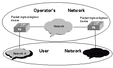
Figure 3-1 BPDU Tunnel implementation
3.2 Configuring BPDU Tunnel
The following table describes the BPDU Tunnel configuration tasks.
Table 3-1 Configure BPDU Tunnel
|
Operation |
Command |
Description |
|
Enter system view |
system-view |
- |
|
Enable BPDU TUNNEL function of the system |
vlan-vpn tunnel |
Configure BPDU TUNNEL function, required |
|
Enter Ethernet port view |
interface interface-type interface-number |
- |
|
Enable VLAN VPN function on the Ethernet port |
vlan-vpn enable |
Enable VLAN VPN function on the Ethernet port, required |
3.2.1 Enabling/disabling BPDU Tunnel
Perform the following configuration in system view.
Table 3-2 Enable/disable BPDU Tunnel in system view
|
Operation |
Command |
|
Enable BPDU Tunnel |
vlan-vpn tunnel |
|
Disable BPDU Tunnel |
undo vlan-vpn tunnel |
By default, BPDU Tunnel is disabled.
3.2.2 Enabling/disabling VLAN VPN on Ethernet port
Perform the following configuration in Ethernet port view.
Table 3-3 Enable/disable VLAN VPN in Ethernet port view
|
Operation |
Command |
|
Enable VLAN VPN |
vlan-vpn enable |
|
Disable VLAN VPN |
undo vlan-vpn |
By default, the VLAN VPN is disabled on all the ports.
& Note:
In Ethernet port view, VLAN VPN and STP are not compatible with each other and cannot function at the same time.
3.3 BPDU Tunnel Configuration Example
I. Network requirements
l The S9500 Series Routing Switches are used as the access devices of the operator’s network, that is, Switch C and Switch D in the following figure.
l The S2000 Series Ethernet Switches are used as the access devices of the user network, that is, Switch A and Switch B in the following figure.
l Switch C and Switch D connect to each other through trunk port, enabling the BPDU Tunnel function in system view, and implementing the transparent transmission between user network and operator’s network. VLAN 20 is assigned to the user network.
II. Network diagram
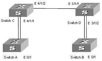
Figure 3-2 Network diagram for BPDU Tunnel configuration
III. Configuration procedure
1) Configure Switch A
# Enable rapid spanning tree protocol (RSTP) on the device.
[H3C] stp enable
# Set the port Ethernet 0/1 as a trunk port and configure it to permit VLAN 10 to pass through.
[H3C] vlan 10
[H3C- Ethernet 0/1] port link-type trunk
[H3C- Ethernet 0/1]port trunk permit vlan 10
2) Configure Switch B
# Enable RSTP on the device.
[H3C] stp enable
# Set the port Ethernet 0/1 as a trunk port and configure it to permit VLAN 10 to pass through.
[H3C] vlan 10
[H3C- Ethernet 0/1] port link-type trunk
[H3C- Ethernet 0/1]port trunk permit vlan 10
3) Configure Switch C
# Enable multiple STP (MSTP) on the device.
[H3C] stp enable
# Enable BPDU Tunnel on the device.
[H3C] vlan-vpn tunnel
# Add the port Ethernet 4/1/1 into VLAN 20.
[H3C] vlan 20
[H3C-Vlan 20] port Ethernet 4/1/1
# First disable STP and then enable VLAN VPN on the port Ethernet 4/1/1.
[H3C] interface Ethernet 4/1/1
[H3C-Ethernet4/1/1] stp disable
[H3C-Ethernet4/1/1] vlan-vpn enable
# Set the port Ethernet 4/1/2 as a trunk port.
[H3C-Ethernet4/1/2] port link-type trunk
# Add the trunk port into all the VLANs.
[H3C-Ethernet4/1/2] port trunk permit vlan all
4) Configure Switch D
# Enable MSTP on the device.
[H3C] stp enable
# Enable BPDU Tunnel on the device.
[H3C] vlan-vpn tunnel
# Add the port Ethernet 3/1/2 into VLAN 20.
[H3C] vlan 20
[H3C- Vlan 20 ]port Ethernet 3/1/2
# First disable the STP protocol and then enable VLAN VPN on the port Ethernet 3/1/2.
[H3C] interface Ethernet 3/1/2
[H3C-Ethernet3/1/2] stp disable
[H3C-Ethernet3/1/2] vlan-vpn enable
# Set the port Ethernet 3/1/1 as a trunk port.
[H3C-Ethernet3/1/1] port link-type trunk
# Add the trunk port into all the VLANs.
[H3C-Ethernet3/1/1] port trunk permit vlan all
[H3C-Ethernet3/1/1] port trunk permit vlan all
# Add Ethernet3/1/3 into VLAN20.
[H3C] vlan 20
[H3C- Vlan 20] port Ethernet 3/1/3
# Disable STP Protocol on Ethernet3/1/3 and enable VLAN-VPN.
[H3C] interface Ethernet3/1/3
[H3C-Ethernet3/1/3] stp disable
[H3C-Ethernet3/1/3] vlan-vpn enable
![]() Caution:
Caution:
l The STP protocol must be enabled on those devices that have enabled BPDU TUNNEL; otherwise after BPDUs of the client network enter the switch, they will not be processed by the CPU, so their MAC addresses cannot be replaced, that is to say, they cannot be transparently transported.
l The port that has enabled VLAN-VPN must be configured as the access port; the intermediate operator network must be configured as trunk link;
l BPTU TUNNEL cannot be configured on ports that have enabled DOT1X, GVRP, GMRP, STP and NTDP protocols.