- Table of Contents
-
- H3C S9500 Series Routing Switches Operation Manual-(V1.01)
- 00-1Cover
- 01-Getting Started Operation
- 02-Port Operation
- 03-VLAN-QinQ Operation
- 04-Network Protocol Operation
- 05-Routing Protocol Operation
- 06-Multicast Protocol Operation
- 07-QACL Operation
- 08-MPLS Operation
- 09-STP Operation
- 10-Security Operation
- 11-Reliability Operation
- 12-System Management Operation
- 13-PoE Operation
- 14-NAT-URPF-VPLS Operation
- 15-Integrated Management Operation
- 16-Appendix
- Related Documents
-
| Title | Size | Download |
|---|---|---|
| 02-Port Operation | 351 KB |
Table of Contents
Chapter 1 Port Configuration Overview
Chapter 2 Ethernet Port Configuration
2.2 Ethernet Port Configuration
2.2.1 Entering Ethernet Port View
2.2.2 Enabling/Disabling an Ethernet Port
2.2.3 Setting Ethernet Port Description
2.2.4 Setting the Duplex Attribute of the Ethernet Port
2.2.5 Setting Speed on the Ethernet Port
2.2.6 Setting the Cable Type for the Ethernet Port
2.2.7 Enabling/Disabling Flow Control for the Ethernet Port
2.2.8 Enabling/Disabling Jumbo Frames’ Passing a Card
2.2.9 Setting Broadcast/Multicast Suppression on Ethernet Port
2.2.10 Setting the Ethernet Port Mode
2.2.11 Setting the Link Type for the Ethernet Port
2.2.12 Adding the Ethernet Port to Specified VLANs
2.2.13 Setting the Default VLAN ID for the Ethernet Port
2.2.14 Setting the VLAN VPN Feature on a Port
2.2.15 Copying Port Configurations to Other Ports
2.2.17 Setting the Ethernet Port in Loopback Mode
2.3 Displaying and Debugging Ethernet Port
2.4 Ethernet Port Configuration Example
2.5 Ethernet Port Troubleshooting
Chapter 3 Link Aggregation Configuration
3.1.1 Introduction to Link Aggregation
3.2 Link Aggregation Configuration
3.2.1 Enabling/Disabling LACP at Port
3.2.2 Creating/Deleting an Aggregation Group
3.2.3 Adding/Deleting an Ethernet Port into/from an Aggregation Group
3.2.4 Configuring/Deleting Aggregation Group Description
3.2.5 Configuring System Priority
3.2.6 Configuring Port Priority
3.3 Displaying and Debugging Link Aggregation
3.4 Link Aggregation Configuration Example
Chapter 4 POS Port Configuration
4.2.2 Adding/Deleting POS Port into/from VLAN
4.2.3 Enabling/Disabling POS Port
4.2.4 Configuring POS Port Description
4.2.5 Setting Frame Format of POS Port
4.2.6 Setting Scrambling Function of POS Port
4.2.7 Setting Alarm Threshold for the POS Port
4.2.8 Setting Clock Mode on POS Port
4.2.9 Setting Polling Interval of the State Timer on POS Port
4.2.10 Setting CRC Check Bit Length of POS Port
4.2.11 Setting Loopback Mode of POS Port
4.2.12 Setting Overhead Byte Type of POS Port
4.2.13 Setting Timeout Time for PPP Negotiation
4.2.14 Setting MTU of POS Port
4.3 Displaying and Debugging POS Port Configuration
4.4 POS Port Configuration Example
4.5 Troubleshooting POS Port Configuration
Chapter 5 RPR Port Configuration
5.2.1 Configuration Preparations
5.2.2 RPR Port Configuration Tasks
5.3 Displaying and Debugging RPR Port Configuration
Chapter 6 IDS Linkage Configuration
6.2 Requirements for Switch (Router)
6.3 Linkage Configuration of IDS with the Switch (Router)
6.3.1 Configuration Description
6.4 IDS Linkage Configuration Example
6.5 Displaying IDS Linkage Configuration
Chapter 7 Port Isolation Configuration
7.2.1 Configuring an Isolated Group
7.2.2 Configuring an Uplink Port in the Isolated Group
7.2.3 Configuring Isolated Ports for an Isolated Group
7.3 Port Isolation Configuration Example
Chapter 8 Packet Statistics Configuration
8.1 Introduction to Egress Packet Statistics
8.1.1 Configuring Egress Packet Statistics Counters
Chapter 1 Port Configuration Overview
The H3C S9500 Series Routing Switches (hereinafter referred to as S9500 series) support these LPU boards:
l XP2
l XP4
l XK1
l GT8P
l F32G
l GP12
l GP24
l GT12
l GT24
l GV48
l FP20
l FT48
l P4G8
l SP4
l UP1
l VP2
The Ethernet ports of S9500 series have the following features:
l XP2 provides two 10GE optical ports and works in 10 Gbps full duplex mode without user intervention.
l XP4 provides four 10GE optical ports and works in 10 Gbps full duplex mode without user intervention.
l XK1 provides one 10GE optical/electrical port and works in 10 Gbps full duplex mode without user intervention.
l GT8P provides four 1000 Mbps SFP optical ports and eight 10/100/1000 Mbps electrical ports. The optical ports in 1000 Mbps full duplex mode without user intervention. The electrical ports support auto-MDI/MDI-X and can work in 1000 Mbps full duplex, 100 Mbps half/full duplex, or 10 Mbps half/full duplex mode.
l F32G provides 32 ´ 10/100 Mbps electrical ports and four 1000 Mbps optical ports. The 10/100 Mbps electrical ports support auto-MDI/MDI-X and can work in half duplex, full duplex or auto-negotiation mode. They can negotiate with other network devices to choose optimum duplex mode and speed. The 1000 Mbps optical ports work in 1000 Mbps full duplex mode without user intervention.
l GP12 provides 12 ´ 1000 Mbps optical ports and works in 1000 Mbps full duplex mode without user intervention.
l GP24 provides 24 ´ 1000 Mbps optical/electrical ports and works in 1000 Mbps full duplex mode without user intervention.
l GT12 provides 12 ´ 10/100/1000 Mbps electrical ports, supports auto-MDI/MDI-X, and can work in 1000 Mbps full duplex, 100 Mbps half/full duplex, or 10 Mbps half/full duplex mode.
l GT24 provides 24 ´ 10/100/1000 Mbps electrical ports, supports auto-MDI/MDI-X, and can work in 1000 Mbps full duplex, 100 Mbps half/full duplex, or 10 Mbps half/full duplex mode.
l GV48 provides 48 ´ 10/100/1000 Mbps electrical ports, which work in 1000 Mbps full duplex mode (the rate and duplex mode are user configurable), and supports POE power supply.
l FP20 provides 20 ´ 100 Mbps optical ports and works in 100 Mbps full duplex mode without user intervention.
l FT48 provides 48 ´ 10/100 Mbps electrical ports, supports auto-MDI/MDI-X, and can work in half duplex, full duplex or auto-negotiation mode. It can negotiate with other network devices to choose optimum duplex mode and speed.
l P4G8 provides four POS ports and eight 1000 Mbps optical ports. The POS ports work at the speed of 155 Mbps; the 1000 Mbps optical ports work in 1000 Mbps full duplex mode without user intervention.
l SP4 provides four 2.5 Gbps POS optical ports. The POS ports work at the speed of 2.5 Gbps without user intervention.
l UP1 provides one 10 Gbps POS optical ports. The POS ports work at the speed of 10 Gbps without user intervention.
l VP2 provides two 10 Gbps RPR ports. The RPR ports work at the speed of 10 Gbps without user intervention.
Chapter 2 Ethernet Port Configuration
2.1 Ethernet Port Overview
S9500 series can provide conventional Ethernet ports, fast Ethernet ports, 1000 Mbps Ethernet ports and 10 Gbps Ethernet ports. The configurations of these Ethernet ports are basically the same, which will be described in the following sections.
2.2 Ethernet Port Configuration
The following sections describe Ethernet port configuration tasks:
l Enabling/Disabling an Ethernet Port
l Setting Ethernet Port Description
l Setting the Duplex Attribute of the Ethernet Port
l Setting Speed on the Ethernet Port
l Setting the Cable Type for the Ethernet Port
l Enabling/Disabling Flow Control for the Ethernet Port
l Enabling/Disabling Jumbo Frames’ Passing a Card
l Setting Broadcast/Multicast Suppression on Ethernet Port
l Setting the Ethernet Port Mode
l Setting the Link Type for the Ethernet Port
l Adding the Ethernet Port to Specified VLANs
l Setting the Default VLAN ID for the Ethernet Port
l Setting the VLAN VPN Feature on a Port
l Copying Port Configurations to Other Ports
l Setting the Ethernet Port in Loopback Mode
2.2.1 Entering Ethernet Port View
Before configuring the Ethernet port, enter Ethernet port view first.
Perform the following configuration in system view.
Table 2-1 Entering Ethernet port view
|
Operation |
Command |
|
Enter Ethernet port view |
interface interface-type interface-number |
2.2.2 Enabling/Disabling an Ethernet Port
After configuring the related parameters and protocol of the port, you can use undo shutdown command to enable the port. If you do not want a port to forward data any more, use shutdown command to disable it.
Perform the following configuration in Ethernet port view.
Table 2-2 Enabling/disabling an Ethernet port
|
Operation |
Command |
|
Disable an Ethernet port |
shutdown |
|
Enable an Ethernet port |
undo shutdown |
By default, the port is enabled.
2.2.3 Setting Ethernet Port Description
To distinguish the Ethernet ports, you can use the following command to make some necessary descriptions.
Perform the following configuration in Ethernet port view.
Table 2-3 Setting Ethernet port description
|
Operation |
Command |
|
Set an Ethernet port description |
description text |
|
Delete the Ethernet port description |
undo description |
By default, an Ethernet port has no description.
2.2.4 Setting the Duplex Attribute of the Ethernet Port
To configure a port to send and receive data packets at the same time, set it to full-duplex. To configure a port to either send or receive data packets at a time, set it to half-duplex. If the port has been set to auto-negotiation mode, the local and peer ports will automatically negotiate about the duplex mode.
Perform the following configuration in Ethernet port view.
Table 2-4 Setting the duplex attribute for the Ethernet port
|
Operation |
Command |
|
Set duplex attribute for Ethernet port |
duplex { auto | full | half } |
|
Restore the default duplex attribute of Ethernet port |
undo duplex |
Note that, 10/100 Mbps electrical Ethernet port can operate in full-duplex, half-duplex or auto-negotiation mode. The10/100/1000 Mbps electrical Ethernet port can operate in full duplex, half duplex or auto-negotiation mode. When the port operates at 1000 Mbps or in auto mode, the duplex mode can be set to full (full duplex) or auto (auto-negotiation). The optical 100/1000 Mbps and 10 Gbps Ethernet ports work in full duplex mode without user intervention.
The port defaults the auto (auto-negotiation) mode.
2.2.5 Setting Speed on the Ethernet Port
You can use the following command to set the speed on the Ethernet port. If the speed is set to auto-negotiation mode, the local and peer ports will automatically negotiate about the port speed.
Perform the following configuration in Ethernet port view.
Table 2-5 Setting speed on the Ethernet port
|
Operation |
Command |
|
Set Ethernet port speed |
speed { 10 | 100 | 1000 | 10000 | auto } |
|
Restore the default speed on Ethernet port |
undo speed |
Note that, the 10/100 Mbps electrical Ethernet port can operate at 10 Mbps, 100 Mbps and in auto mode. You can set it accordingly. The 10/100/1000Mbps electrical Ethernet port can operate at 10 Mbps, 100 Mbps, or 1000 Mbps as per different requirements. However in half duplex mode, the port cannot operate at 1000 Mbps or in auto mode. The 100 Mbps optical Ethernet port supports 100 Mbps; the 1000 Mbps optical Ethernet port supports 1000 Mbps; the 10 Gbps optical Ethernet port supports 10 Gbps without user intervention.
By default, the speed of the port is in auto mode.
2.2.6 Setting the Cable Type for the Ethernet Port
The Ethernet port supports the straight-through and cross-over network cables. The following command can be used for configuring the cable type.
Perform the following configuration in Ethernet port view.
Table 2-6 Setting the type of the cable connected to the Ethernet port
|
Operation |
Command |
|
Set the type of the cable connected to the Ethernet port |
mdi { across | auto | normal } |
|
Restore the default type of the cable connected to the Ethernet port |
undo mdi |
Note that, the settings only take effect on 10/100 Mbps and 10/100/1000 Mbps electrical ports.
By default, the cable type is auto (auto-recognized). That is, the system can automatically recognize the type of cable connecting to the port.
2.2.7 Enabling/Disabling Flow Control for the Ethernet Port
After enabling flow control in both the local and the peer switch, if congestion occurs in the local switch, the switch will inform its peer to pause packet sending. Once the peer switch receives this message, it will pause packet sending, and vice versa. In this way, packet loss is reduced effectively. The flow control function of the Ethernet port can be enabled or disabled through the following command.
Perform the following configuration in Ethernet port view.
Table 2-7 Enabling/disabling flow control for the Ethernet port
|
Operation |
Command |
|
Enable Ethernet port flow control |
flow-control |
|
Disable Ethernet port flow control |
undo flow-control |
By default, Ethernet port flow control is disabled.
2.2.8 Enabling/Disabling Jumbo Frames’ Passing a Card
During large throughput data switching, like file transmission, a card may encounter jumbo frames larger than the standard Ethernet frame length. The following command can be used to enable jumbo frames to pass a card or disable them from passing a card.
Perform the following configuration in system view.
Table 2-8 Enabling/disabling jumbo frames’ passing a card
|
Operation |
Command |
|
Enable Jumbo frames to pass the card on a specified slot, and set the maximum length of Jumbo frames allowed to pass the card |
jumboframe enable [ jumboframe-value ] slot slot-num |
|
Disable Jumbo frames from passing the card on a specified slot |
jumboframe disable slot slot-num |
By default, jumbo frames are allowed to pass cards.
& Note:
The system supports discrete values of Jumbo frame lengths ranging from 1536 to 10240. However, effective Jumbo frame values fall into several sections: the effective Jumbo frame value for the 1536-1552 section is 1552, that for the 1552-9022 section is 9022, that for the 9022-9122 section is 9122, and that for the 9122-10240 section is 10240.
2.2.9 Setting Broadcast/Multicast Suppression on Ethernet Port
To prevent port congestion resulting from broadcast/multicast packet flooding, the switch supports broadcast/multicast suppression. You can enable broadcast/multicast suppression by setting the speed percentage or bandwidth values..
Perform the following configuration in Ethernet port view.
Table 2-9 Setting broadcast/multicast suppression on Ethernet port
|
Operation |
Command |
|
Configure broadcast suppression ration Ethernet port |
broadcast-suppression { ratio | bandwidth bandwidth } |
|
Restore the default setting of broadcast suppression on Ethernet port |
undo broadcast-suppression |
|
Configure multicast suppression ration Ethernet port |
multicast-suppression { ratio | bandwidth bandwidth } |
|
Restore the default setting of multicast suppression on Ethernet port |
undo multicast-suppression |
![]() Caution:
Caution:
l You cannot enable both broadcast suppression and multicast suppression simultaneously on the same card. Namely, once you have enabled broadcast suppression on some ports of a card, you cannot enable multicast suppression on the other ports of the card, and vice versa.
l If multicast suppression is enabled, broadcast packets are also suppressed at the same time, while broadcast suppression does not work on multicast suppression.
l No distinction is made between known multicast and unknown multicast for multicast suppression.
By default, the broadcast suppression ratio is 50%, while the multicast suppression ratio is 100%.
2.2.10 Setting the Ethernet Port Mode
Most ports adopt the LAN mode for general data exchange. The port must work in WAN mode, however, if it needs special frame format for data transfer (such as in fiber transmission). You can configure network mode available on the port using the port-mode command.
Perform the following configuration in Ethernet port view.
Table 2-10 Setting the Ethernet port mode
|
Operation |
Command |
|
Set the Ethernet port mode |
port-mode { wan | lan } |
|
Restore the default Ethernet port mode |
undo port-mode |
By default, Ethernet ports works in LAN mode. 10GE Ethernet ports support WAN mode.
2.2.11 Setting the Link Type for the Ethernet Port
Perform the following configuration in Ethernet port view.
Table 2-11 Setting the link type for the Ethernet port
|
Operation |
Command |
|
Configure the port as access port |
port link-type access |
|
Configure the port as hybrid port |
port link-type hybrid |
|
Configure the port as trunk port |
port link-type trunk |
|
Restore the default link type, that is, the access port |
undo port link-type |
You can configure three types of ports concurrently on the same switch, but you cannot switch between trunk port and hybrid port. You must turn it first into access port and then set it as other type. For example, you cannot configure a trunk port directly as hybrid port, but first set it as access port and then as hybrid port.
By default, the port is access port.
2.2.12 Adding the Ethernet Port to Specified VLANs
The following commands are used for adding an Ethernet port to a specified VLAN. The access port can only be added to one VLAN, while the hybrid and trunk ports can be added to multiple VLANs.
Perform the following configuration in Ethernet port view.
Table 2-12 Adding the Ethernet port to specified VLANs
|
Operation |
Command |
|
Add the current access port to a specified VLAN |
port access vlan vlan-id |
|
Add the current hybrid port to specified VLANs |
port hybrid vlan vlan-id-list { tagged | untagged } |
|
port trunk permit vlan { vlan-id-list | all } |
|
|
Remove the current access port from to a specified VLAN |
undo port access vlan |
|
Remove the current hybrid port from to specified VLANs |
undo port hybrid vlan vlan-id-list |
|
Remove the current trunk port from specified VLANs |
undo port trunk permit vlan { vlan-id-list | all } |
Note that the access port shall be added to an existing VLAN other than VLAN 1. The VLAN to which Hybrid port is added must have been existed.
After adding the Ethernet port to specified VLANs, the local port can forward packets of these VLANs. The hybrid and trunk ports can be added to multiple VLANs, thereby implementing the VLAN intercommunication between peers. For the hybrid port, you can configure to tag some VLAN packets, based on which the packets can be processed differently.
2.2.13 Setting the Default VLAN ID for the Ethernet Port
Since the access port can only be included in one VLAN only, its default VLAN is the one to which it belongs. The hybrid port and the trunk port can be included in several VLANs, it is necessary to configure the default VLAN ID. If the default VLAN ID has been configured, the packets without VLAN Tag will be forwarded to the port that belongs to the default VLAN. When sending the packets with VLAN Tag, if the VLAN ID of the packet is identical to the default VLAN ID of the port, the system will remove VLAN Tag before sending this packet.
Perform the following configuration in Ethernet port view.
Table 2-13 Setting the default VLAN ID for the Ethernet port
|
Operation |
Command |
|
Set the default VLAN ID for the hybrid port |
port hybrid pvid vlan vlan-id |
|
Set the default VLAN ID for the trunk port |
port trunk pvid vlan vlan-id |
|
Restore the default VLAN ID of the hybrid port to the default value |
undo port hybrid pvid |
|
Restore the default VLAN ID of the trunk port to the default value |
undo port trunk pvid |
Note that: to guarantee the proper packet transmission, the default VLAN ID of local hybrid port or Trunk port should be identical with that of the hybrid port or Trunk port on the peer switch.
By default, the VLAN of hybrid port and trunk port is VLAN 1 and that of the access port is the VLAN to which it belongs
2.2.14 Setting the VLAN VPN Feature on a Port
A VLAN Tag consists of only 12 bits (defined by IEEE802.1Q), so Ethernet Switches can support up to 4k VLANs. In networking, especially in MAN (metropolitan area network), a large numbers of VLANs are required to segment users. In this case, 4k VLANs are not enough.
The port VLAN VPN feature of the switch can provide duplex VLAN Tags to a packet, namely, mark the packet with another VLAN Tag besides the original one, thus to provide 4k x 4k VLANs to meet user’s demands for VLANs. At the same time, the port VLAN VPN feature provides the following functions: using the original VLAN Tag to differentiate users and services, and using the new VLAN Tag to load service and VPN users. These make VLAN configuration simple and practicable. Through VLAN VPN configuration, Ethernet Switches can meet the requirement in MAN.
If VLAN VPN is enabled on a port, every packet received on the port (no matter whether the packet carries a VLAN Tag or not) will be given a new Tag that specifies the default VLAN of this port. Thus, if the port receives a packet that already carries a VLAN Tag, the packet will get two Tags; if the part receives an untagged packet, the packet will be given a default VLAN Tag of the port.
Perform the following configuration in Ethernet port view.
Table 2-14 Setting the port VLAN VPN feature
|
Operation |
Command |
|
Enable the port VLAN VPN feature |
vlan-vpn enable |
|
Disable the port VLAN VPN feature |
undo vlan-vpn |
Note that if any of GVRP, STP, and 802.1x has been enabled on a port, the VLAN VPN feature cannot be enabled on the port.
By default, the port VLAN VPN feature is disabled.
2.2.15 Copying Port Configurations to Other Ports
To keep the configurations of other ports consistent with a specified port, you can use copy configuration command to copy the configurations of that specified port to other ports. Such configurations may involve: STP setting, QoS setting, LACP setting, and port setting. The detailed table is as follows:
Table 2-15 Configurations that can be copied
|
Attribute |
Detailed Setting |
|
STP setting |
Enable/disable STP |
|
Port priority |
|
|
Path cost |
|
|
Link attributes(point-to-point or not) |
|
|
Port mCheck |
|
|
Max transmission speed |
|
|
Enable/disable root protection |
|
|
Enable/disable loop protection |
|
|
Edge or non-edge port |
|
|
Reset ARP or not |
|
|
QoS setting |
Define/apply flow template |
|
Traffic reshaping |
|
|
Traffic redirection |
|
|
Packet filtering |
|
|
Priority re-assignment |
|
|
Traffic statistics |
|
|
Traffic mirroring |
|
|
Rate limiting |
|
|
Port setting |
Permitted VLAN ID |
|
Default VLAN ID |
|
|
Add ports to VLAN |
|
|
Default 802.1p priority |
|
|
Port speed, duplex mode |
|
|
Port link type |
|
|
LACP |
Enable/disable LACP on the port |
& Note:
l Using copy configuration command will clear protocol VLAN attributes of the destination port, but it can not copy protocol VLAN attributes of source port to the destination port.
l Using the copy configuration command, you can only copy the configurations of Ethernet ports, Gigabit Ethernet ports and aggregation groups.
Perform the following configuration in system VLAN
Table 2-16 Copying port configurations to other ports
|
Operation |
Command |
|
Copy port configurations to other ports |
copy configuration source { interface-type interface-number | aggregation-group agg-id } destination { interface-list [ aggregation-group agg-id ] | aggregation-group agg-id } |
Note that if the copy source is an aggregation group, the Active port with the smallest number will be taken as the source; if the copy destination is an aggregation group, the configurations of all ports in the group will be updated to the configurations of the source. You cannot specify a dynamic aggregation group as the destination port of the copy command.
2.2.16 Setting Port Hold Time
If the Down/Up operation is implemented on ports too frequently, the switch may fail. Therefore, you can configure port hold time to prohibit frequent change of the port status.
Perform the following configuration in system view.
Table 2-17 Setting the port hold time
|
Operation |
Command |
|
Set the port hold time |
link-status hold hold-time |
|
Restore the default value |
undo link-status hold |
By default, the port hold time is set to 3 seconds.
2.2.17 Setting the Ethernet Port in Loopback Mode
Perform the following configuration in Ethernet port view.
Table 2-18 Setting the Ethernet port in loopback mode
|
Operation |
Command |
|
Set the Ethernet port in loopback mode |
loopback { external | internal } |
|
Remove loopback configuration on the port |
undo loopback |
By default, the Ethernet port is set in loopback mode. At present, the Ethernet ports of the S9500 series switches do not support the external loopback mode.
2.3 Displaying and Debugging Ethernet Port
After the above configuration, execute display command in any view to display the running of the Ethernet port configuration, and to verify the effect of the configuration.
Execute reset command in user view to clear the statistics information of the port.
Table 2-19 Displaying and debugging Ethernet port
|
Operation |
Command |
|
Display all the information of the port |
display interface interface-type | interface-type interface-number [ packets ] |
|
Display hybrid port or trunk port |
display port { hybrid | trunk } |
|
Display the statistics information of the port |
display counters [ rate ] { inbound | outbound } interface [ interface-type ] |
|
Clear the statistics information of the port |
reset counters interface [ interface_type | interface-type interface-number | |
|
View Jumbo frame configuration on all cards |
display jumboframe configuration |
& Note:
l The S9500 series do not support the Loopback External mode.
l When 802.1x is enabled on a port, the statistics information of the port cannot be cleared.
l By default, the display counters command displays the traffic statistic information of all ports in service.
l The supported Jumbo frame length ranges, as well as the default values, may vary from card to card.
2.4 Ethernet Port Configuration Example
I. Network requirements
Switch A is connected to Switch B through Trunk port GigabitEthernet2/1/1. Configure the Trunk port with default VLAN ID, so that: when receiving the packets without VLAN Tag, the port can forward them to the member ports belonging to the default VLAN; when it sending the packets with VLAN Tag and the packet VLAN ID is the default VLAN ID, the Trunk port remove the packet VLAN Tag and forward the packet.
II. Network diagram
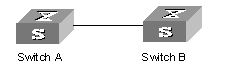
Figure 2-1 Network diagram for Ethernet port configuration
III. Configuration procedure
The following configurations are used for Switch A. Please configure Switch B in the similar way.
# Enter the Ethernet port view of GigabitEthernet2/1/1.
[H3C] interface gigabitethernet2/1/1
# Set the GigabitEthernet2/1/1 as a trunk port and allows VLANs 2, 6 through 50, and 100 to pass.
[H3C-GigabitEthernet2/1/1] port link-type trunk
[H3C-GigabitEthernet2/1/1] port trunk permit vlan 2 6 to 50 100
# Create the VLAN 100.
[H3C] vlan 100
# Configure the default VLAN ID of GigabitEthernet2/1/1 as 100.
[H3C-GigabitEthernet2/1/1] port trunk pvid vlan 100
2.5 Ethernet Port Troubleshooting
Symptom 1: Default VLAN ID configuration fails.
Solution: Take the following steps:
l Execute the display interface or display port command to check if the port is a trunk port or a hybrid port. If it is neither of them, configure it as a trunk or hybrid port.
l Then configure the default VLAN ID.
Symptom 2: The port is in down status.
Solution: Please check
l If the cable connection is correct and if the optical fiver cable is inversely connected.
l If the shutdown command is used on the port.
l If the right optical module is inserted.
Chapter 3 Link Aggregation Configuration
3.1 Overview
3.1.1 Introduction to Link Aggregation
Link aggregation means aggregating several ports together to implement the outgoing/incoming payload balance among the member ports and enhance the connection reliability. Link aggregation may be manual aggregation, dynamic LACP aggregation or static LACP aggregation. For the member ports in an aggregation group, their basic configurations must be the same. That is, if one is a trunk port, others must also be; when it turns into access port, then others must change to access port.
Basic configuration includes STP setting, QoS setting, VLAN setting, and port setting. The STP setting includes STP enabling/disabling, link attribute (point-to-point or not), STP priority, path cost, max transmission speed, loop protection, root protection, edge port or not. The QoS setting includes traffic limiting, priority marking, default 802.1p priority, bandwidth assurance, congestion avoidance, traffic redirection, and traffic statistics. The VLAN setting includes permitted VLAN types, default VLAN ID. The port setting includes port link type.
One S9500 series routing switch can support up to 920 aggregation groups. IDs 1 though 31 indicate manual or static aggregation groups. IDs 32 through 64 are reserved. IDs 65 though 192 are routed trunks; IDs 193 through 920 indicate dynamic aggregation groups. The systems with MPLS VPN cards only support seven load balancing aggregation groups; those without MPLS VPN cards support 31 load balancing aggregation groups. The systems with FE boards using EX chips only supports seven load balancing aggregation groups.
& Note:
At present, S9500 series also support trans-board aggregation. The trans-board aggregation is the same as the intra-board aggregation.
3.1.2 Introduction to LACP
Link aggregation control protocol (LACP) based on the IEEE802.3ad standard can be used in dynamic link aggregation. An LACP-enabled port sends link aggregation control protocol data units (LACPDUs) to tell the peer about its system priority, system MAC address, port priority, port number and operation key. After receiving the information from the sender, the receiver compares it with the locally saved information about other ports, chooses member ports for the aggregation group and reaches agreement about if a port can join or leave a dynamic aggregation group.
During port aggregation, LACP generates a configuration mix according to the port configuration (rate, duplex, basic configuration, management key), which is called an operation key. The management key of an LACP-enabled dynamic aggregation port is 0 by default. The management key of an LACP-enabled static aggregation port is the same as the aggregation group ID. In a dynamic aggregation group, the member ports must have the same operation key. In manual and static aggregation groups, the active ports have the same operation key.
3.1.3 Aggregation Types
Port aggregation can be divided into manual aggregation, dynamic LACP aggregation and static LACP aggregation.
I. Manual aggregation and static LACP aggregation
Both manual aggregation and static LACP aggregation are configured manually, and cannot be added or removed automatically by the system. A manual or static LACP aggregation group must contain a member port at least. In the case of one port in an aggregation group, the unique method for you to remove the port from the aggregation group is to delete the aggregation group. By default, the system disables the LACP for the manual aggregation port. You are prohibited to enable the LACP for the manual aggregation port. By default, the system enables the LACP for the static aggregation port. When a static aggregation group is removed, the member ports will form one or more dynamic LACP aggregation groups with LACP enabled. You are prohibited to disable the LACP for the static aggregation port.
In manual and static aggregation groups, ports can be in active or inactive state. The port in active state can transmit and receive user service packets, but the port in inactive state cannot. The active port with the minimum port number serves as the master port, while others as slave ports.
In a manual aggregation group, the system sets the ports to active or inactive state based on these rules:
l Based on the descending order of priority levels from full duplex/high speed, to full duplex/low-speed, to half duplex/high speed and till half duplex/low speed, the system sets the port with the highest priority to active state, and others to inactive state.
l The system sets to inactive state the ports which cannot aggregate with the master port, due to hardware limit (such as trans-board aggregation is forbidden).
l The system sets to inactive state the ports with basic configurations different from the active port.
In a static aggregation group, the system sets the ports to active or inactive state based on these rules:
l Based on the descending order of priority levels from full duplex/high speed, to full duplex/low-speed, to half duplex/high speed and till half duplex/low speed, the system sets the port with the highest priority to active state, and others to inactive state.
l The system sets to inactive state the active port connecting to the different peer devices, or the port connecting to the same peer device but locating in the different aggregation group.
l The system sets to inactive state the ports which cannot be aggregated with the port, due to hardware limit (for example, trans-board aggregation is forbidden).
l The system sets to inactive state the ports with basic configurations different from the active port.
Since only a defined number of ports can be added in an aggregation group, then if the active ports in an aggregation group exceed the maximum threshold for that group, the system shall set some ports with smaller port numbers (in ascending order) as active ports and others as inactive ports. Both active and inactive ports can transmit and receive LACP protocol, but the inactive ports cannot forward user service packets.
II. Dynamic LACP aggregation
The system can create/delete automatically dynamic LACP aggregations, and you cannot add/delete member ports into/from dynamic LACP aggregation. The system can also aggregate one port, which is called single port aggregation. The dynamic LACP aggregation LACP is in enabled state. The system can only aggregate the ports with the same speed, duplex attribute, device connection, basic configuration.
Since only a defined number of ports can be added in an aggregation group, then if the current member ports in an aggregation group exceed the maximum threshold for that group, the system shall set some ports with smaller device ID (system priority + system MAC address) and smaller port ID (port priority + port number) as active ports, and others as inactive ports. If the maximum threshold is not exceeded, all member ports are active ports. Both active and inactive ports can transmit and receive LACP protocol, but the inactive ports cannot forward user service packets. In an aggregation group, the active port with the minimum port number serves as the master port, while others as slave ports. When comparing device ID, the system compare system priority first, and then system MAC address in the case of the same system priority. The smaller device ID is regarded as higher priority. When comparing port ID, the system compares port priority first, and then port number in the case of the same port priority. The smaller port ID is regarded as higher priority. If the device ID changes to higher priority, the active and inactive state of the member ports in an aggregation group depends on the device port ID. You can also set system and port priority to define active and inactive ports.
3.1.4 Load Sharing
I. Types of Load sharing
In terms of load balancing, link aggregation may be load balancing aggregation and non-load balancing aggregation The 9500 series allocate IP packet load sharing according to destination and source IP addresses. The switches allocate non-IP packet load sharing according to source and destination MAC addresses. You can check protocol types in determining if to use IP or MAC addresses. The packet with 0800 ETYPE Ethernet field is IP packet. In general, the system only provides limited resources. The system will always allocate hardware aggregation resources to the load balancing aggregation groups with higher priority levels. When the load sharing aggregation resources are used up for existing aggregation groups, newly-created aggregation groups will be non-load sharing ones. The priority levels (in descending order) for allocating load sharing aggregation resources are as follows:
l Aggregation groups of special ports with hardware aggregation resources included, such as non-limited-speed 10GE ports
l Aggregation groups that probably reach the maximum potential rate after the resources are allocated to them
l Aggregation groups with the minimum master port numbers if they reach the equal rate with other groups after the resources are allocated to them
l Manual aggregation has a higher priority level than static aggregation, and static aggregation has a higher priority level than dynamic aggregation
l Under the same conditions, an aggregation group that has occupied resources has a higher priority level than an aggregation group waiting for occupied
When aggregation groups of higher priority levels appear, the aggregation groups of lower priority levels release their hardware resources. For single-port aggregation groups, if they can transmit and receive packets normally without occupying hardware resources, they shall not occupy the resources.
II. Port state
In a aggregation group, its ports may be in active or inactive state and only the active ports can transmit and receive user service packets, but not inactive ports. The active port with the minimum port number serves as the master port, while others as slave ports.
In a aggregation group, the system sets the ports to active or inactive state based on these rules:
l Based on the descending order of priority levels from full duplex/high speed, to full duplex/low-speed, to half duplex/high speed and till half duplex/low speed, the system sets the port with the highest priority to active state, and others to inactive state.
l The system sets to inactive state the ports which cannot aggregate with the master port, due to hardware limit.
l The system sets to inactive state the ports with basic configurations different from the master port.
Since only a defined number of ports can be supported in an aggregation group, then if the active ports in an aggregation group exceed the port quantity threshold for that group, the system shall set some ports with smaller port numbers (in ascending order) as active ports and others as inactive ports. The active ports can transmit and receive user service packets, but not inactive ports.
A load sharing aggregation group may contain several active ports, but a non-load sharing aggregation group can only have one active port, while others as inactive ports.
3.2 Link Aggregation Configuration
The following sections describe link aggregation tasks:
l Enabling/Disabling LACP at Port
l Creating/Deleting an Aggregation Group
l Adding/Deleting an Ethernet Port into/from an Aggregation Group
l Configuring/Deleting Aggregation Group Description
& Note:
l When configuring an aggregation group, the status of GVRP feature configured on the master port is reserved, but that on the slave port is disabled.
l When adding a port to an existing aggregation group, the GVRP feature on the port is disabled.
l When the master port leaves an aggregation group, the status of GVRP feature on both the group and port is reserved; when a slave port leaves an aggregation group, the GVRP feature on the port is disabled.
l When configuring GVRP feature on any port in an aggregation group, the configuration is mapped to the master port of the group.
l When querying the GVRP feature configured on any port in an aggregation group, the returned result is about the master port of the group.
For details, refer to the “VLAN-QinQ” part of this manual
3.2.1 Enabling/Disabling LACP at Port
You should first enable LACP at the ports before performing dynamic aggregation, so that both parties can agree on adding/deleting the ports into/from a dynamic LACP aggregation group.
Perform the following configuration in Ethernet port view.
Table 3-1 Enabling/disabling LACP on a port
|
Operation |
Command |
|
Enable LACP on a the port |
lacp enable |
|
Disable LACP on a the port |
undo lacp enable |
By default, LACP is not enabled at the port.
Note that:
l You cannot enable LACP at the mirroring port, the port with static MAC address configured, and the port with static ARP configured, port with 802.1x enabled.
l You are inhibited to enable LACP at the port in a manual aggregation group.
l You can add a port with LACP disabled to a static LACP aggregation group, and then the LACP will be enabled automatically.
3.2.2 Creating/Deleting an Aggregation Group
You can use the following command to create/delete an aggregation group (for manual aggregation and static link aggregation). When you delete an aggregation group, all its member ports are disaggregated.
Perform the following configuration in system view.
Table 3-2 Creating/deleting an aggregation group
|
Operation |
Command |
|
Create an aggregation group |
link-aggregation group agg-id mode { manual | static } |
|
Delete an aggregation group |
undo link-aggregation group agg-id |
During creating an aggregation group, if it already exists in the system but contains no member port, it changes to the new type. When you change a static LACP aggregation group to a manual one, LACP shall be disabled at the member ports automatically.
& Note:
Port aggregation includes manual aggregation, static aggregation and dynamic aggregation.
l In the manual aggregation mode, ports working at different rates can be aggregated. Manual aggregation can be load balancing aggregation if the aggregation resource is available. In this case, if the traffic rate shared by a low-rate port exceeds the maximum rate of the port, packets may be lost.
l In the static aggregation mode, ports working at different rates can also be aggregated. However, the selected/standby state of statically aggregated ports is determined by the transmission rate. Only the ports with the maximum rate and in full-duplex mode can be selected to forward traffic, while other standby ports do not forward traffic.
3.2.3 Adding/Deleting an Ethernet Port into/from an Aggregation Group
You can add/delete ports into/from an aggregation group.
Perform the following configuration in the corresponding view.
Table 3-3 Adding/deleting an Ethernet port into/from an aggregation group
|
Operation |
Command |
|
Add an Ethernet port into the aggregation group (Ethernet port view) |
port link-aggregation group agg-id |
|
Delete an Ethernet port from the aggregation port (Ethernet port view) |
undo port link-aggregation group |
|
Aggregate Ethernet ports (system view) |
link-aggregation interface-name1 to interface-name2 [ both ] |
Note that:
l You cannot add a mirrored port, a port configured with a static MAC address, a port with 802.1x enabled, a POS port, and a VPN port into an aggregation group.
l You must delete the aggregation group, instead of the port, if the aggregation group contains only one port.
l When master port enables VLAN VPN, aggregation is permitted in the system. Because the link type of slave port will always keep same as that of master port. When both master port and slave have VLAN VPN disabled, aggregation is permitted in the system, it is average aggregation. After the port enabling VLAN VPN, aggregation is not permitted in the system, at the same time, the system will tell users that the slave port in the aggregation group conflict with the master port on VLAN VPN.
l When a port is added into an aggregation group, the original ARP information of the port will be lost.
3.2.4 Configuring/Deleting Aggregation Group Description
You can use the following command to create/delete aggregation group description (for manual aggregation and static link aggregation).
Perform the following configuration in system view.
Table 3-4 Configuring/deleting aggregation group description
|
Operation |
Command |
|
Set an aggregation group description |
link-aggregation group agg-id description alname |
|
Delete the aggregation group description |
undo link-aggregation group agg-id description |
By default, an aggregation group has no description.
& Note:
You cannot configure the description for a dynamic aggregation group.
3.2.5 Configuring System Priority
The LACP refers to system IDs in determining if the member ports are active and inactive for a dynamic LACP aggregation group. The system ID consists of two-byte system priority and six-byte system MAC, that is, system ID = system priority + system MAC. In comparing system IDs, the system first compares system priority values; if they are equal, then it compares system MAC addresses. The smaller system ID is considered prior.
Changing system priority may affect the priority levels of member ports, and further their active or inactive state.
Perform the following configuration in system view.
Table 3-5 Configuring system priority
|
Operation |
Command |
|
Configure system priority |
lacp system-priority system-priority-value |
|
Restore the default system priority |
undo lacp system-priority |
By default, system priority is 32,768.
3.2.6 Configuring Port Priority
The LACP compares system IDs first and then port IDs (if system IDs are the same) in determining if the member ports are active or inactive ones for a dynamic LACP aggregation group. If the ports in an aggregation group exceed the port quantity threshold for that group, the system shall set some ports with smaller port IDs as active ports and others as inactive ports. The port ID consists of two-byte port priority and two-byte port number, that is, port ID = port priority + port number. The system first compares port priority values and then port numbers and the small port ID is considered prior.
Perform the following configuration in Ethernet port view.
Table 3-6 Configuring port priority
|
Operation |
Command |
|
Configure port priority |
lacp port-priority port-priority-value |
|
Restore the default port priority |
undo lacp port-priority |
By default, port priority is 32,768.
3.3 Displaying and Debugging Link Aggregation
After the above configuration, execute the display command in any view to display the running of the link aggregation configuration, and to verify the effect of the configuration.
In user view, execute the reset command to clear statistics on the LACP-enabled port, and the debugging command to enable LACP debugging.
Table 3-7 Displaying and debugging link aggregation
|
Operation |
Command |
|
Display summary information of all aggregation groups |
display link-aggregation summary |
|
Display detailed information of a specific aggregation group |
display link-aggregation verbose [ agg-id ] |
|
Display the local device ID |
display lacp system-id |
|
Display detailed link aggregation information at the port |
display link-aggregation interface interface-type interface-number [ to interface-type interface-number ] |
|
Clear LACP statistics on the port |
reset lacp statistics [ interface interface-type interface-number [ to interface-type interface-number ] ] |
|
Disable/enable LACP state debugging |
[ undo ] debugging lacp state [ interface interface-type interface-number [ to interface-type interface-number ] ] { { actor-churn | mux | partner-churn | ptx | rx }* | all } |
|
Disable/enable LACP packet debugging |
[ undo ] debugging lacp packet [ interface interface-type interface-number [ to interface-type interface-number ] ] |
|
Disable/enable link aggregation error debugging |
[ undo ] debugging link-aggregation error |
|
Disable/enable link aggregation event debugging |
[ undo ] debugging link-aggregation event |
3.4 Link Aggregation Configuration Example
I. Network requirements
Switch A connects switch B with three aggregation ports, numbered as Ethernet2/1/1 to Ethernet2/1/3, so that incoming/outgoing load can be balanced among the member ports.
II. Network diagram
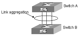
Figure 3-1 Network diagram for link aggregation configuration
III. Configuration procedure
The following only lists the configuration for switch A, and that on switch B is similar.
1) Manual aggregation
# Create aggregation group 1.
[H3C] link-aggregation group 1 mode manual
# Add Ethernet ports Ethernet2/1/1 to Ethernet2/1/3 into aggregation group 1.
[H3C] interface ethernet2/1/1
[H3C-Ethernet2/1/1] port link-aggregation group 1
[H3C-Ethernet2/1/1] interface ethernet2/1/2
[H3C-Ethernet2/1/2] port link-aggregation group 1
[H3C-Ethernet2/1/2] interface ethernet2/1/3
[H3C-Ethernet2/1/3] port link-aggregation group 1
# When the aggregation group numbers are continuous, you can directly aggregate multiple ports into a group. The group number is allocated by the system.
[H3C] link-aggregation ethernet2/1/1 to ethernet2/1/3 both
2) Static LACP aggregation
# Create aggregation group 1.
[H3C] link-aggregation group 1 mode static
# Add Ethernet ports Ethernet2/1/1 to Ethernet2/1/3 into aggregation group 1.
[H3C] interface ethernet2/1/1
[H3C-Ethernet2/1/1] port link-aggregation group 1
[H3C-Ethernet2/1/1] interface ethernet2/1/2
[H3C-Ethernet2/1/2] port link-aggregation group 1
[H3C-Ethernet2/1/2] interface ethernet2/1/3
[H3C-Ethernet2/1/3] port link-aggregation group 1
3) Dynamic LACP aggregation
# Enable LACP on Ethernet ports Ethernet2/1/1 to Ethernet2/1/3.
[H3C] interface ethernet2/1/1
[H3C-Ethernet2/1/1] lacp enable
[H3C-Ethernet2/1/1] interface ethernet2/1/2
[H3C-Ethernet2/1/2] lacp enable
[H3C-Ethernet2/1/2] interface ethernet2/1/3
[H3C-Ethernet2/1/3] lacp enable
You must set basic configuration, rate and duplex attribute consistent at both ends to aggregate successfully the LACP-enabled ports into a dynamic aggregation group and achieve load sharing.
Chapter 4 POS Port Configuration
4.1 POS Port Overview
Packet over SONET/SDH (POS) is a technology used in MAN (metropolitan area network) and WAN (wide area network) for data packet transmission. S9500 series use synchronous digital hierarchy (SDH) and Synchronous Optical Network (SONET) as its physical layer protocol, map data packets of varying length into SDH/SONET synchronous load, and provide a type of high-speed, reliable point-to-point data connections.
The POS ports of S9500 series work at the rates of STM-1/OC-3 (155.52 Mbps), STM-16 (2.5 Gbps) and STM-64 (10 Gbps), use point-to-point protocol (PPP) at the data link layer and internet protocol (IP) at the network layer.
4.2 POS Port Configuration
The following sections describe POS port configuration tasks:
l Adding/Deleting POS Port into/from VLAN
l Configuring POS Port Description
l Setting Frame Format of POS Port
l Setting Scrambling Function of POS Port
l Setting Alarm Threshold for the POS Port
l Setting Clock Mode on POS Port
l Setting Polling Interval of the State Timer on POS Port
l Setting CRC Check Bit Length of POS Port
l Setting Loopback Mode of POS Port
l Setting Overhead Byte Type of POS Port
l Setting Timeout Time for PPP Negotiation
4.2.1 Entering POS Port View
Before configuring the POS port, enter POS port view first.
Perform the following configuration in system view.
Table 4-1 Entering POS port view
|
Operation |
Command |
|
Enter POS port view |
interface pos interface-number |
4.2.2 Adding/Deleting POS Port into/from VLAN
You can add the current POS port into a designated VLAN, so that it can forward the packets of that VLAN. If the VLAN already contain other ports, you cannot add a POS port into it, vice versa.
Perform the following configuration in POS port view.
Table 4-2 Adding/deleting POS port into/from VLAN
|
Operation |
Command |
|
Add a POS port into the VLAN |
pos access vlan vlan-id |
|
Delete a POS port from the VLAN |
undo pos access vlan |
Note that:
l The VLAN added to the POS port must be existent and is configured with the corresponding VLAN interface and IP address. In addition, it cannot be VLAN 1.
l If there are ports of all types in this VLAN, then the POS port cannot be added into this VLAN, and vice versa.
4.2.3 Enabling/Disabling POS Port
When the corresponding parameters and protocols are configured, you can use undo shutdown command to enable the POS port. You also can use undo shutdown to disable it if you want to stop data forwarding at it.
Perform the following configuration in POS port view.
Table 4-3 Enabling/Disabling POS port
|
Operation |
Command |
|
Enable POS port |
shutdown |
|
Disable POS port |
undo shutdown |
By default, POS port is enabled.
4.2.4 Configuring POS Port Description
Perform the following configuration in POS port view.
Table 4-4 Configuring POS port description
|
Operation |
Command |
|
Configure a POS port description |
description text |
|
Delete the POS port description |
undo description |
By default, a POS port has no description.
4.2.5 Setting Frame Format of POS Port
The POS port supports two frame formats: SDH format and SONET format.
Perform the following configuration in POS port view.
Table 4-5 Setting frame format of POS port
|
Operation |
Command |
|
Set frame format of POS port to SDH/SONET |
frame-format { sdh | sonet } |
|
Restore the default frame format |
undo frame-format |
By default, the frame of a POS port is in SDH format.
4.2.6 Setting Scrambling Function of POS Port
The POS port supports scrambling over payload data, to avoid occurrence of too many consecutive 1s or 0s and facilitate receiving and subtracting line clock signals.
Perform the following configuration in POS port view.
Table 4-6 Setting scrambling function of POS port
|
Operation |
Command |
|
Enable scrambling function of POS port |
scramble |
|
Disable scrambling function of POS port |
undo scramble |
By default, scrambling function is enabled on a POS port.
4.2.7 Setting Alarm Threshold for the POS Port
Using the following command, you can set the thresholds of SD (signal degrade) and SF (signal failure) alarms. SD and SF alarms are used to indicate the performance of the current line. Both of them are caused by the B2 error detected by the receiving end, but their thresholds for the bit error rate are different, and the SF threshold for bit error rate is higher than that of the SD, so SF alarm is more serious than the SD alarm. That is to say when there are few error bits, the line gives out the SD alarm; and when the bit error rate reaches a certain extent, which means the line performance is seriously degraded, the line gives out the SF alarm.
Perform the following configuration in POS port view.
Table 4-7 Setting alarm threshold of POS port
|
Operation |
Command |
|
Set the SD and SF thresholds of POS port |
threshold { sd | sf } value |
|
Restore to the defaults |
undo threshold { sd | sf } |
The threshold is expressed in 10e – X. X is an integer ranging from 3 to 9. By default, SD = 10e - 6, and SF = 10e – 3.
Note that SD threshold must be smaller than SF threshold.
4.2.8 Setting Clock Mode on POS Port
The POS port supports two clock modes:
l Master clock mode, using internal clock signals
l Slave clock mode, using line clock signals
When two switches are connected through POS ports, you should set one POS port in master clock mode and the other in slave clock mode. Otherwise, the clocks of the two switches may be asynchronous, and packet loss may occur.
Perform the following configuration in POS port view.
Table 4-8 Setting clock mode on POS port
|
Operation |
Command |
|
Set clock mode of POS port as master |
clock master |
|
Set clock mode of POS port as slave |
clock slave |
|
Restore the default clock mode of the POS port |
undo clock |
By default, a POS port is in slave clock mode.
4.2.9 Setting Polling Interval of the State Timer on POS Port
The protocol running at the POS port (PPP for example) regularly sends ECHO messages in the polling interval of the state polling timer at the port. If it receives no response messages from the peer within the specified time limit, it regards that the peer is anomalous.
Perform the following configuration in POS port view.
Table 4-9 Setting polling interval of the state timer on POS port
|
Operation |
Command |
|
Set polling interval of the state timer of POS port |
timer hold seconds |
|
Restore the default polling interval |
undo timer hold |
By default, the polling interval is 10 seconds. If you set the polling interval as 0, the system does not perform link validity check.
4.2.10 Setting CRC Check Bit Length of POS Port
The POS port supports the CRC check bit of 16 bits and 32 bits.
Perform the following configuration in POS port view.
Table 4-10 Setting CRC check bit length of POS port
|
Operation |
Command |
|
Set CRC check bit length of POS port to 16 bits |
crc 16 |
|
Set CRC check bit length of POS port to 32 bits |
crc 32 |
|
Restore the default length of CRC check bit |
undo crc |
By default, the CRC check bit is of 32 bits.
& Note:
The 10GE POS port does not support the 16-bit CRC check bit.
4.2.11 Setting Loopback Mode of POS Port
Loopback is set for testing some special functions. It is not used when the system works normally.
Perform the following configuration in POS port view.
Table 4-11 Setting loopback mode of POS port
|
Operation |
Command |
|
Set loopback mode of the POS port to internal |
loopback internal |
|
Set loopback mode of the POS port to external |
loopback external |
|
Disable loopback of the POS port |
undo loopback |
By default, internal or external loopback is disabled on a POS port.
![]() Caution:
Caution:
l You cannot set both internal loopback and external echo on a POS port.
l When switching between internal and external loopback modes, you must delete the original loopback setting before setting new loopback.
4.2.12 Setting Overhead Byte Type of POS Port
SDH provides many overhead byte types for monitoring at different levels.
Signal label byte C2 belongs to high-order path overhead byte, and is used to indicate the multiplexing structure and message payload of the VC (virtual container) frame.
Path trace byte J1 also belongs to high-order overhead byte, and is used to check port connectivity at path level.
Perform the following configuration in POS port view.
Table 4-12 Setting overhead byte type of POS port
|
Operation |
Command |
|
Set overhead byte type for POS port |
flag c2 flag-value flag { j0 | j1 } { sdh | sonet } flag-value |
|
Restore the default overhead byte type |
undo flag c2 undo flag { j0 | j1 } { sdh | sonet } |
By default, c2 is 0x16 (hexadecimal); J0 and J1 are default.
C2, J0 and J1 configuration should be consistent at both ends. Otherwise, the system may give alarms. The frame format of overhead bytes J0 and J1 must be consistent at both POS ports. Otherwise, the system cannot read the peer field values correctly.
4.2.13 Setting Timeout Time for PPP Negotiation
During negotiation, PPP shall retransmit the message if it receives no the response message from the peer within the defined time limit. You can customize the timeout time for PPP negotiation.
Perform the following configuration in POS port view.
Table 4-13 Setting timeout time for PPP negotiation
|
Operation |
Command |
|
Set timeout time for PPP negotiation |
ppp timer negotiate seconds |
|
Restore the default value |
undo ppp timer negotiate |
By default, the timeout time for PPP negotiation is 3 seconds.
4.2.14 Setting MTU of POS Port
Perform the following configuration in POS port view.
Table 4-14 Set MTU of POS port
|
Operation |
Command |
|
Set the MTU of the POS port |
mtu mtu-value |
By default, the MTU is 1,500 bytes.
Note that you must disable the port by using the shutdown command first and then use the undo shutdown command to enable it again if the MTU values are different between both ends. In this case, as the result of negotiation between both ports, the smaller value will be used as the MTU.
4.3 Displaying and Debugging POS Port Configuration
After the above configurations are completed, you can use the display command in any view to view the running of POS port and further to check configuration result.
Execute reset command in user view to clear statistics of the POS port.
Table 4-15 Displaying and debugging POS port configuration
|
Operation |
Command |
|
Display all information about the POS port |
display interface pos [ interface-number ] |
|
Clear statistics of the POS port |
reset counters interface pos [ interface_number ] |
|
Enable/disable POS port debugging |
[ undo ] debugging ppp { { ipcp | lcp } { all | error | event | packet | state } | all | core event | ip packet | mpls-multicast packet | mpls-unicast packet | osi-npdu } [ interface { aux | pos } interface-number ] |
4.4 POS Port Configuration Example
I. Networking requirement
Connect the POS ports of Switch A and Switch B with a pair of (Rx and Tx) single mode optical fiber cables; use PPP protocol and enable scrambling function at the port; the clocks of Switch A are provided by Switch B.
II. Network diagram
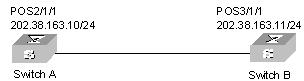
Figure 4-1 Network diagram for POS port configuration
III. Configuration procedure
1) Configure Switch A:
# Configure POS port 2/1/1.
[SwitchA] vlan 2
[SwitchA-vlan2] interface vlan 2
[SwitchA-Vlan-interface2] ip address 202.38.163.10 255.255.255.0
[SwitchA-Vlan-interface2] quit
[SwitchA] interface pos 2/1/1
[SwitchA-Pos2/1/1] pos access vlan 2
2) Configure Switch B:
# Configure POS port 3/1/1.
[SwitchB] vlan 2
[SwitchB-vlan2] interface vlan 2
[SwitchB-Vlan-interface2] ip address 202.38.163.11 255.255.255.0
[SwitchB-Vlan-interface2] quit
[SwitchB] interface pos 3/1/1
[SwitchB-Pos3/1/1] pos access vlan 2
[SwitchB-Pos3/1/1] clock master
4.5 Troubleshooting POS Port Configuration
Symptom 1: The POS port is down at the physical layer.
Solution: Please check
l Whether the optical fiber cables are connected correctly at the POS ports. There should be two optical fiber cables, respectively stand for receive and transmit. They cannot be connected inversely. If the Tx and Rx ends of a optical fiber cable both are connected to the same POS port, then you can see the information “loopback detected” when using the display interface pos command even if loopback function is not enabled yet.
l Whether the right optical module (providing POS ports) is inserted.
Symptom 2: The POS port has been enabled in the physical layer, but the link does not report the Up state.
Solution: Please check
l Whether inconsistent physical parameters, such as POS port clock, scrambling setting, are set at both ends.
l Whether inconsistent link data layer protocols are set at both ends.
l Whether this or the peer end is not configured with an IP address.
l Whether the port CRC settings are consistent at both ends.
l Whether loopback is set on the port.
l Whether the VLAN to which the port belongs has been deliberately disabled using shutdown.
Symptom 3: Serious IP packet loss.
Solution: Possible causes include:
l Incorrect clock configuration at the POS port (which has resulted in a large amount of CRC error)
l Inconsistent MTU (maximum transmission unit) configuration at both ends
Chapter 5 RPR Port Configuration
5.1 RPR Standard Overview
Resilient packet ring (RPR) is a new MAC layer protocol designed for transferring mass data services over MANs. With multiple technology advantages, such as high utilization of ring bandwidth, self-healing ability, and plug and play nodes, it can match the requirements for next-generation MANs. RPR adopts two-fiber bi-directional ring topology.
5.1.1 RPR Port Overview
RPR contains three port views: one logical port and two physical ports. Most command configurations related to Ethernet ports can be inherited to the RPR logical port. You can make physical layer-associated settings in the physical port view, such as SDH overhead configuration. RPR physical ports include POS and 10GE ports. The following section describes both RPR POS and RPR 10GE port views, but presents only RPR POS examples. A physical port serves as the slave interface of the logical port. For example, if the logical port is RPR POS3/1/1, the physical ports are RPR POS3/1/1.1 and RPR POS3/1/1.2.
5.2 Configuring RPR Ports
5.2.1 Configuration Preparations
& Note:
l Many configuration commands for an RPR logical port are the same as configuration commands for an Ethernet port. All the following Ethernet configuration commands can be used for the configuration of RPR ports: broadcast suppression, RPR port description, setting link types for RPR ports, adding access ports to a specified VLAN, adding hybrid ports to a specified VLAN, adding trunk ports to a specified VLAN, setting default VLAN ID for a hybrid RPR port, setting default VLAN ID for a trunk RPR port, traffic control, priority configuration, loopback. You can also refer to Chapter 2 “Ethernet Port Configuration”.
l RPR logical ports support the STP and QoS/ACL functions.
RPR supports plug and play, and can bear services almost without configurations. In general, you do not need to configure RPR. For some special purposes such as debugging, you can also modify the configuration by referring to the related commands.
5.2.2 RPR Port Configuration Tasks
The following table describes RPR port configuration tasks.
Table 5-1 RPR port configuration tasks
|
Configuration steps |
Command |
Description |
|
Enter system view |
system-view |
- |
|
Enter RPR logical port view |
Interface rpr interface-number |
Required. To enter physical port view, you need to add “.1” and “.2” to the end of the logical port name. |
|
Configure station names |
rpr station-name string |
Optional |
|
Configure forced switchover on the port |
rpr admin-request { fs | ms | idle } { ringlet0 | ringlet1 } |
Optional. Note that the receiving and sending sub-rings for port 1 on the panel are Ringlet0 and Ringlet1 respectively. The receiving and sending sub-rings for port 2 on the panel are Ringlet1 and Ringlet0 respectively. Here Ringlet0 and Ringlet1 are both receiving sub-rings. |
|
Test node connectivity |
rpr echo { mac mac-address | station-name namestring } [-c value] [-s value] [-r value ] [-t value ] |
Optional |
|
Configure default RPR ring ID |
rpr default-rs { ringlet0 | ringlet1 } |
Optional. Default selection rings are all sending sub-rings. |
|
Map tag, mpls and ip priority types to RPR priority |
rpr cos-precedence-map { tag | mpls | ip } value value0 value1 value2 value3 value4 value5 value6 value7 |
Optional. By default, for packets with a tag, the mapping will be implemented as per tag; for packets without a tag, if they are MPLS packets, the mapping will be implemented as per MPLS priority; if they are IP packets instead of MPLS packets, the mapping will be implemented as per IP priority; if they are either MPLS packets or IP packet, the priority will be mapped to Class C. |
|
Configure node protection mode |
rpr protect-mode { steer | wrap } |
Optional. By default, the protection mode is Steer mode. |
|
Configure reserved bandwidth |
rpr rate-limit { high | low | medium | reserved } { ringlet0 | ringlet1 } value |
Optional.. |
|
Set protection recovery mode |
rpr reversion-mode { revertive | non-revertive} |
Optional. The default RPR protection recovery mode is revertive. |
|
Set static ring information |
rpr static-rs { mac-address} { ringlet0 | ringlet1 } |
Optional. By default, the static ring information is not configured. You cannot configure the same bridge MAC address for the two nodes on a ring. Ringlet0 and Ringlet1 are both sending sub-rings |
|
Configure node weight |
rpr weight { ringlet0 | ringlet1 } value |
Optional. By default, weight is 0. |
|
Set the values of the timers for sending ATD frames periodically |
rpr timer { atd value | fdd value | holdoff value | stability value | tp-fast value| tp-slow value| tc-fast value| tc-slow value| wtr value} |
Optional. By default, it is 1 second. |
|
Set physical port type |
port-type { 10gpos | 10ge } |
Optional. When the setting changes, the board will restart automatically, and then switch to the new RPR port type. Note that the following commands are to be carried out in the RPR POS physical port view |
|
Configure clock source |
clock-source [ line | internal ] |
Optional. The default is internal. |
|
Configure SONET/SDH overhead bytes |
flag { c2 c2-value | j0 j0-value | j1 j1-value |
Optional. In scrambling mode, c2 is 0x16 by default. In non-scrambling mode, c2 is 0xCF by default. Both j0 and j1 are “NetEngine” by default. The c2, j0 and j1 of the transceiver should be the same at both ends respectively. Otherwise, the system gives alarms. |
|
Configure the framing mode if it is FRAMER at the physical layer |
Frame––format {sdh | sonet } |
Optional. By default, the encryption mode is configured as SDH. |
|
Configure threshold for SD BER and SF BER |
sdh threshold {sd-ber value | sf-ber value } |
Optional. By default, SD BER is 6, and SF BER is 3. |
|
Exit from RPR POS physical port view and enter the user view |
return |
- |
|
Enable RPR debugging |
[ undo ] debugging rpr { all | topology | protection | controlframe | ringselection | tp-frame } |
Optional. By default, RPR debugging is disabled. |
|
Display port configuration |
display interface [ interface-type | interface-type interface-number [ packets ] ] |
Optional. You can use the display command in any view. |
|
Clear port statistics |
reset counters interface [ interface-type ] interface-number |
Optional. You can use the reset counters interface command in user view |
|
Display all RPR defects. |
display rpr defect [ rprpos [ interface-number ] ] |
Optional. The value 1 indicates defects are found. The value 0 indicates there is no defect. |
|
Display configurable RPR fairness parameter values |
display rpr fairness [ rprpos [ interface-number ] |
Optional. |
|
Display protection information |
display rpr protection [ rprpos [ interface-number ] ] |
Optional. If you do not specify a port, the command displays the protection information of all RPR ports. |
|
Display integrated ring selection table information |
display rpr rs-table [overall | static | dynamic | vrrp] [ rprpos [ interface-number ] ] |
Optional. Without any parameter, the command displays the integrated ring selection table of all RPR rings. |
|
Display all configurable RPR timer values |
display rpr timers [ rprpos [ interface-number ] |
Optional. |
|
Display topology information |
display rpr topology { all | ring | local | stations } [verbose] |
Optional. If you do not specify a port, the command displays the topology information about all RPR ports. |
|
Query the traffic statistics information of packets from other nodes on the ring to the local node or from the local node to other nodes |
display rpr statistics { dmac | smac } [mac address] [ rpr [ interface-number ] ] |
Optional |
Note that the bridge MAC addresses of the nodes in the ring cannot be the same.
5.2.3 Configuration Example
I. Network requirements
Use a pair of optic fiber cables to connect the RPR ports of Node A, Node B, Node C and Node D. The physical port 0 connects the physical port 1.
II. Network diagram
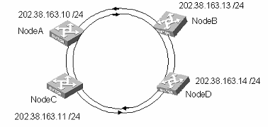
Figure 5-1 Network diagram for RPR port configuration
III. Configuration procedure
The following section takes Node A configuration as an example. Other node configurations are similar.
# Add RPR port 2/1/1 to VLAN 2.
[Node A] vlan 2
[Node A-vlan2] interface vlan-interface 2
[Node A-Vlan-interface2] ip address 202.38.163.10 255.255.255.0
[Node A-Vlan-interface2] quit
[Node A] vlan 2
[Node A-Vlan2] port rpr 2/1/1
& Note:
RPR can bear services almost without configuration.
5.3 Displaying and Debugging RPR Port Configuration
Execute the display command in any view to display the RPR port configuration.
Table 5-2 Displaying and debugging RPR port configuration
|
Configuration |
Command |
Description |
|
Enable RPR debugging |
[ undo ] debugging rpr { all | topology | protection | controlframe | mac | ringselection | tp-frame } |
Optional. By default, RPR debugging is disabled |
|
Display port configuration |
display interface [ interface-type | interface-type interface-number ] |
Optional. You can use the display command in any view |
|
Display all RPR defects |
display rpr defect [ rprpos [ interface-number ] ] |
Optional. The value 1 indicates defects are found. The value 0 indicates there is no defect |
|
Display configurable RPR fairness parameter values |
display rpr fairness |
Optional |
|
Display protection information |
display rpr protection [ rprpos [ interface-number ] ] |
Optional. If you do not specify a port, the command displays the protection state information about all RPR ports |
|
Display integrated ring selection table information |
display rpr rs-table [overall | static | dynamic | vrrp] [ rprpos [ interface-number ] ] |
Optional. Without any parameter, the command displays integrated ring selection table information about all RPR rings by default |
|
Display all configurable RPR timer values |
display rpr timers [ rprpos [ interface-number ] |
Optional |
|
Display topology information |
display rpr topology { all | ring | local | stations } [verbose] [ rprpos [ interface-number ] |
Optional. If you do not specify a port, the command displays the topology information about all RPR ports |
|
Query the traffic statistics information of packets from other nodes on the ring to the local node or from the local node to other nodes |
display rpr statistics { dmac | smac } [mac address] [ rpr [ interface-number ] ] |
Optional |
Chapter 6 IDS Linkage Configuration
6.1 Overview
6.1.1 Necessity
Users always resort to a single type of security products to satisfy a specific security need. For example, they purchase firewalls for purpose of preventing attacks of suspicious data packets, password machines for encrypting transmitted data, and intrusion detection systems (IDSs) for detecting intrusion.
With the increasing application, this expensive purchase method causes many management problems, as well as potential security problems. In most circumstances, security products need to cooperate with other security products and network devices, to ensure the system can detect and prevent corresponding attacks straight from the source. This kind of cooperation is called linkage. The switch supports IDS linkage, namely cooperation between the switch and IDS, to ensure effectively the security of the entire network.
6.1.2 Operations Involved
From the perspective of network security, IDS linkage contains the following operations:
l Filtering: Filters viruses, malicious ActiveX programs and others.
l Invasion detection: Detects suspicious behavior on the network based on protocol signatures, and then notifies firewalls and switches (routers) for processing.
6.2 Requirements for Switch (Router)
The switch (router) should
l Provide at least one monitor port, with the port rate of 100 Mbps or 1000 Mbps.
l Support SNMP v3, as well as proxy address setting.
l Support access control list (ACL) function to filter the IP address, TCP/UDP port and other fields in the packet header. Support setting life time and filtering type for each access list entry.
6.2.1 Requirements for IDS
The IDS supports SNMP v3, and sends access control messages to switches through the SET operation.
6.3 Linkage Configuration of IDS with the Switch (Router)
6.3.1 Configuration Description
& Note:
To guarantee normal operation, you must configure SNMP on both the switch and IDS. For SNMP configuration, refer to the “System Management Operation” part of H3C S9500 Series Routing Switches Operation Manual
The following sections describe the IDS linkage configuration tasks:
l Configuring port mirroring
l Enabling IDS linkage on port
I. Configuring port mirroring
Port mirroring means you can duplicate the data from mirroring ports to the monitor ports, for data analysis and monitoring. The switch supports many-to-one mirroring, that is, you can duplicate packets from multiple ports to one monitor port. You can specify the packets sent by the specified ports to be monitored. You can specify the direction of the monitored packet. For example, you can set to monitor only outgoing packets on the specified ports.
For the S9500 series, you can use the mirroring group to configure port mirroring function. Each mirroring group contains one monitor port and a group of mirroring ports.
II. Enabling IDS linkage on port
After configuring port mirroring, you must enable IDS linkage function on the corresponding port to make IDS linkage take effect.
6.3.2 Configuration Tasks
Table 6-1 IDS linkage configuration tasks
|
Configuration item |
Command |
Description |
|
Enter system view |
system-view |
- |
|
Configure port mirroring |
mirroring-group groupid { inbound | outbound } mirroring-port-list &<1-8> mirrored-to monitor-port |
Required |
|
Enter Ethernet port view |
interface interface-type interface-number |
The prompt character for the Ethernet view depends on the input port. |
|
Enable IDS linkage on the port |
ids-acl enable |
Required |
|
Display port mirroring |
display mirroring-group { integer<1-20> | <cr> } |
Optional. You can use the display command in any view. |
|
Display IDS linkage information |
display ids { all | controlled-interface | name name | source ip-addr | destination ip-addr } |
& Note:
l If the IDS linkage is enabled on the Ethernet port, the system may give alarms when you enable IDS linkage again. However, this does not affect the state of IDS linkage.
l The monitor port configured in a mirroring group connects the IDS monitoring port.
l The IDS linkage is enabled on the mirroring ports in the port monitoring group.
l The system identifies packet filter rules generated by IDS and does not save nodes generated by IDS. The packet filter rules generated by IDS will not Buildrun. You cannot view the packet filter rule by executing the display this command in port view.
6.4 IDS Linkage Configuration Example
I. Network requirements
l As shown in Figure 6-1, the IDS detects the host with IP address 192.168.1.20, which connects to the switch port Ethernet3/1/1.
l Before being controlled by the IDS, the host (192.168.1.20) can ping successfully the host (192.168.1.205, which connects to the switch port Ethernet3/1/3.)
l After being controlled by the IDS, the host (192.168.1.20) fails to ping host (192.168.1.205)
l The IDS device’s IP address is 192.168.1.247. Its management port connects the switch port Ethernet3/1/47; its monitoring port connects the switch port Ethernet3/1/48.
l The management port with the IP address 192.168.1.1 on the switch communicates with the IDS.
& Note:
Controlling means that the IDS monitors traffic data from mirroring ports. When detecting suspicious traffic data, the IDS device sends to a switch (router) or firewall the traffic data protocol header information (IP/TCP/UDP/ICMP) and action information. The switch (router) or firewall blocks the specified traffic or port.
II. Network diagram
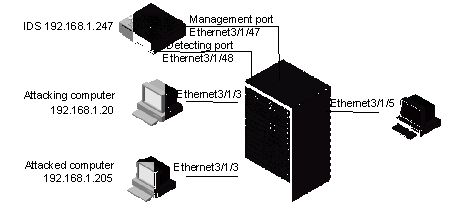
Figure 6-1 Network diagram for IDS linkage configuration
III. Configuration procedure
& Note:
Only the commands related to the switch (router) are listed here.
<H3C> system-view
[H3C] mirroring-group 1 inbound Ethernet 3/1/1 mirrored-to Ethernet 3/1/48
[H3C]vlan 192
[H3C-vlan192]port Ethernet3/1/1 Ethernet3/1/3 Ethernet3/1/5 Ethernet3/1/47
[H3C-vlan192]interface vlan-interface 192
[H3C-Vlan-interface192]ip add 192.168.1.1 255.255.255.0
[H3C] interface Ethernet 3/1/1
[H3C-Ethernet3/1/1] ids-acl enable
[H3C-Ethernet3/1/1] display ids all
6.5 Displaying IDS Linkage Configuration
Execute the display command in any view to display IDS linkage configuration.
Table 6-2 Display IDS linkage configuration
|
Configuration |
Command |
Description |
|
Enable IDS linkage debugging |
debugging ids-acl |
By default, IDS linkage debugging is disabled. |
|
Display IDS linkage configuration information |
display ids { all | controlled-interface | name name | source ip-addr | destination ip-addr } |
You can execute the display ids command in any view. |
Chapter 7 Port Isolation Configuration
7.1 Port Isolation Overview
Using port isolation feature, you can place different user ports into the same VLAN. As these users cannot communicate with each other, the network security is improved, flexible networking scheme is provided, and a lot of VLAN sources are saved.
7.2 Configuration Tasks
|
Configuration tasks |
Description |
Detailed configuration |
|
Configure an isolated group |
Required |
Refer to section 7.2.1 |
|
Required |
Refer to section 7.2.2 |
|
|
Configure isolated ports for an isolated group |
Required |
Refer to section 7.2.3 |
7.2.1 Configuring an Isolated Group
Table 7-2 Configuring an isolated group
|
Operation |
Command |
Description |
|
Enter system view |
system-view |
- |
|
Configure an isolated group |
port-isolate group isolate-group-id |
Required Ports in the isolated group can only communicate with the upstream port. The VLAN where the upstream port of the isolated group is located must contain all the ports in this isolated group |
|
Query isolation information |
display port-isolate group [ isolate-group-id ] [ verbose ] |
You can carry out this command in any view |
7.2.2 Configuring an Uplink Port in the Isolated Group
Table 7-3 Configuring an uplink port in the isolated group
|
Operation |
Command |
Description |
|
Enter system view |
system-view |
- |
|
Enter Ethernet port view or RPR port view |
interface interface-type interface-number |
Required |
|
Configure the upstream port in the isolated group |
port-isolate uplink-port group isolate-group-id |
Required l You can configure the uplink port for the isolated group only after you create the isolated group l The upstream port can only be an Ethernet port or RPR logic port l You can configure only one upstream port for one isolated group. And the uplink port can be an aggregation group, but not a static or dynamic aggregation group |
|
Query isolation information |
display port-isolate group [ isolate-group-id ] [ verbose ] |
You can carry out this command in any view |
7.2.3 Configuring Isolated Ports for an Isolated Group
Table 7-4 Configuring isolated ports for the isolated group
|
Operation |
Command |
Description |
|
Enter system view |
system-view |
- |
|
Enter Ethernet port view or RPR port view |
interface interface-type interface-number |
Required |
|
Configure isolated ports for the isolated group |
port-isolate group isolate-group-id |
Required l You can configure isolated ports for the isolated group only after you create the isolated group. The isolated port can only be configured as an Ethernet port or RPR logic port l One port can join only one isolated port l One port can be either an isolated port or an uplink port, but not both an isolated port and an uplink port in the same isolated group l If the isolated port is a member of an aggregation group, other ports in the aggregation group will also join the isolated group |
|
Query isolation information |
display port-isolate group [ isolate-group-id ] [ verbose ] |
You can carry out this command in any view |
7.3 Port Isolation Configuration Example
I. Network requirements
Users in a community connect to a switch. The switch communicates with the external network through port Ethernt2/1/1. These users are in VLAN 1 and cannot communicate with each other.
II. Network diagram
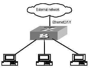
Figure 7-1 Network diagram for port isolation
III. Configuration procedure
# Create isolated group 1.
<H3C>system-view
[H3C] port-isolate group 1
# Configure port Ethernet2/1/2 as an isolated port in isolated group 1.
[H3C] interface Ethernet2/1/2
[H3C-Ethernet2/1/2] port-isolate group 1
# Configure port Ethernet2/1/1 as an upstream port in isolated group 1.
[H3C] interface Ethernet2/1/1
[H3C-Ethernet2/1/1] port-isolate uplink-port group 1
Chapter 8 Packet Statistics Configuration
8.1 Introduction to Egress Packet Statistics
A card provides two sets of counters for monitoring egress packet statistics of the card. The monitored objects include ports, VLANs, ports+VLANs, and cards. In addition to these four types of objects, a traffic class (TC) or a drop precedence (DP) can also be monitored. When monitoring a card, the counters can monitor all TCs and all DPs. Egress packet statistics involves the number of unicast packets, the number of multicast packets, the number of broadcast packets, the number of bridge-filtered packets and the number of dropped packets in congestion. In packet statistic, only the number of packets, rather than the number of bytes, is counted.
& Note:
A card provides only two sets of counters, Counter0 and Counter1, which are independent of each other.
8.1.1 Configuring Egress Packet Statistics Counters
Table 8-1 Configuring egress packet statistics counters
|
Operation |
Command |
Description |
|
Enter system view |
system-view |
- |
|
Configure the monitored objects of the egress packet statistics counters |
set egress { counter0 | counter1 } slot slot-num [ interface interface-type interface-number ] [ vlan vlan-id ] [ tc traffic-class ] [ dp drop-precedence ] |
Required By default, the egress packet statistics counters of a card monitor call ports, all VLANs, all TCs, and all DPs By default, egress packet statistics is disabled for cards |
|
Query counter information |
display egress { counter0 | counter1 } slot slot-num [ clear ] |
The display command can be used in any view |
Note that:
l You cannot configure ports as the objects to be monitored by the egress packet statistics counters on GV48D, GT24D, GP24D, XP4B and XP4CA cards.
l This command does not support egress packet statistics on POS ports not bound to a VLAN.
l After successful configuration, it is necessary to reset the counters to start counting again.
l If the monitored objects are ports, you can use the display current-configuration | include egress command to view the port configuration.