- Table of Contents
-
- H3C Campus Fixed-Port Switches CLI-Based Quick Start Configuration Guide-6W101
- 01-H3C Devices CLI Reference
- 02-Login Management Quick Start Configuration Guide
- 03-Configuration File Management Quick Start Configruation Guide
- 04-Software Upgrade Quick Start Configuration Guide
- 05-Device Management Quick Start Configuration Guide
- 06-NTP Quick Start Configuration Guide
- 07-RBAC Quick Start Configuration Guide
- 08-IRF Quick Start Configuration Guide
- 09-Ethernet Interface Quick Start Configuration Guide
- 10-VLAN Quick Start Configuration Guide
- 11-Port Isolation Quick Start Configuration Guide
- 12-Loop Detection Quick Start Configuration Guide
- 13-QinQ Quick Start Configuration Guide
- 14-MAC Address Table Quick Start Configuration Guide
- 15-Ethernet Link Aggregation Quick Start Configuration Guide
- 16-Spanning Tree Quick Start Configuration Guide
- 17-DHCP Quick Start Configuration Guide
- 18-OSPF Quick Start Configuration Guide
- 19-Static Routing Quick Start Configuration Guide
- 20-Basic RIP Quick Start Configuration Guide
- 21-PBR Quick Start Configuration Guide
- 22-IGMP Snooping Quick Start Configuration Guide
- 23-Packet Filtering Quick Start Configuration Guide
- 24-QoS Quick Start Configuration Guide
- 25-IP Source Guard Quick Start Configuration Guide
- 26-SSH Quick Start Configuration Guide
- 27-Port Security Quick Start Configuration Guide
- 28-VRRP Quick Start Configuration Guide
- 29-PoE Quick Start Configuration Guide
- 30-Mirroring Quick Start Configuration Guide
- 31-Information Center Quick Start Configuration Guide
- 32-SNMP Quick Start Configuration Guide
- 33-LAN Networks Quick Start Configuration Guide
- Related Documents
-
| Title | Size | Download |
|---|---|---|
| 33-LAN Networks Quick Start Configuration Guide | 267.83 KB |
LAN Networks Quick Start Configuration Guide
Copyright © 2022 New H3C Technologies Co., Ltd. All rights reserved.
No part of this manual may be reproduced or transmitted in any form or by any means without prior written consent of New H3C Technologies Co., Ltd.
Except for the trademarks of New H3C Technologies Co., Ltd., any trademarks that may be mentioned in this document are the property of their respective owners.
The information in this document is subject to change without notice.
Contents
Deploying a small-sized campus network
Configuring the access switches
Deploying a small- to medium-sized campus network
Configuring the access switches
Deploying a small-sized campus network
Introduction
The following information uses an example to describe the basic procedure for configuring a small-sized campus network.
Network configuration
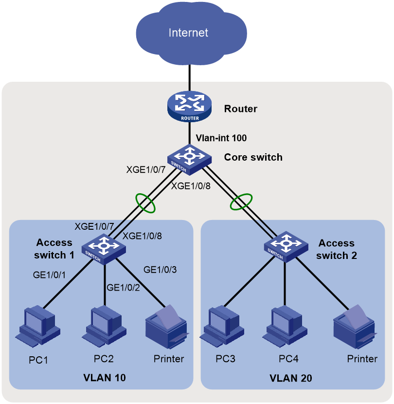
As shown in Figure 1, in a small-sized campus network, the S5130 or S5130S Ethernet switches series are deployed on the access layer. The S5560X or S6520X Ethernet switches series are deployed on the core layer, and an MSR series router is used as the egress router.
Configure the devices to meet the following requirements:
· Configure the spanning tree feature on all the switches to prevent loops.
· Configure link aggregation on the access switches and the core switch to provide high availability.
· Configure VLANs to accommodate services of different departments in the campus and configure VLAN interfaces to provide Layer 3 connectivity for inter-department services.
· Configure the core switch as the DHCP server to dynamically assign IP addresses to campus users.
· Enable DHCP snooping on the access switches to prevent unauthorized DHCP servers from assigning IP addresses to intranet users. Additionally, enable IPSG to prevent intranet users from changing their IP addresses.
Figure 1 Small-sized campus network diagram
Analysis and data preparation
Table 1 shows the procedure of deploying a small-sized campus network.
Table 1 Procedure of deploying a small-sized campus network
|
Step |
Item |
Configuration data |
Remarks |
|
Console login |
Communication parameters (the transmission rate, for example). |
Use a PC to log in to the devices through a terminal emulation program. |
|
|
2. Configure the management IP and Telnet login. |
Management VLAN |
VLAN 5 |
VLAN 1 is the default VLAN. Do not configure VLAN 1 as the management VLAN. This example uses VLAN 5 as the management VLAN. |
|
IP address of the management Ethernet interface or management VLAN interface |
10.10.1.1/24 |
For a switch that has a management Ethernet interface, use the IP address of M-GigabitEthernet 0/0/0 for device login. For a switch that does not have a management Ethernet interface, use the IP address of the management VLAN interface for device login. |
|
|
3. Configure interfaces and VLANs. |
Dynamic aggregation |
· Access switch 1: Uplink aggregate interface Bridge-Aggregation 1 · Access switch 2: Uplink aggregate interface Bridge-Aggregation 1 · Core switch: Downlink aggregate interface Bridge-Aggregation 1 |
Access switches and the core switch are connected through aggregate links. |
|
Port link type |
· Port connected to a PC: Access port · Port connected to a switch: Trunk port |
N/A |
|
|
VLAN IDs |
· Access switch 1: VLAN 10 · Access switch 2: VLAN 20 · Core switch: VLAN 100, VLAN 10, and VLAN 20 |
To isolate Department A and Department B at Layer 2, configure VLAN 10 for Department A and VLAN 20 for Department B. The core switch connects to the egress router through VLAN-interface 100. |
|
|
4. Configure the DHCP server on the core switch. |
DHCP server |
N/A |
N/A |
|
DHCP address pools |
· VLAN 10: DHCP address pool 1 · VLAN 20: DHCP address pool 2 |
PCs in Department A and Department B obtain IP addresses from DHCP address pool 1 and DHCP address pool 2, respectively. |
|
|
5. Configure routes on the core switch. |
IP addresses |
· VLAN-interface 10: 10.10.10.1/24 · VLAN-interface 20: 10.10.20.1/24 · VLAN-interface 100: 10.10.100.1/24 |
The core switch communicates with the egress router through VLAN-interface 100, which is used for the connectivity between the intranet and the egress router. You must configure a default route with the next hop as the egress router. Assign IP addresses to VLAN-interface 10 and VLAN-interface 20 to allow Department A and Department B to visit each other. |
|
6. Configure the egress router. |
IP address of the public network interface |
GE0/2: 202.101.100.2/30 |
GE0/2 on the egress router is the public network interface that connects the router to the Internet. |
|
Public network gateway address |
202.101.100.1/30 |
The egress router communicates with the service provider device through the public network gateway address. To forward intranet packets to the external network, you must configure a default route with the next hop as the public network gateway address. |
|
|
DNS server address |
202.101.100.199 |
The DNS server translates domain names into IP addresses. |
|
|
IP address of the internal network interface |
GE0/1: 10.10.100.2/24 |
GE0/1 on the egress router is the interface connected to the internal network. |
|
|
7. Configure DHCP snooping on the access switches. |
DHCP trusted port |
N/A |
Configure Bridge-Aggregation 1 as a DHCP trusted port. |
|
8. Configure IPSG on the access switches. |
IPSG |
N/A |
Configure IPv4SG to verify source IP address and source MAC address of user packets. |
Procedure
Configuring the access switches
The procedure of configuring access switch 1 is the same as the procedure of configuring access switch 2. This section uses access switch 1 as an example.
1. Log in to the device through the console port (first device access):
# Shut down the PC from which you will log in to the device.
The serial ports on PCs do not support hot swapping. Before connecting a cable to or disconnecting a cable from a serial port on a PC, you must shut down the PC.
# Use the console cable shipped with the device to connect the PC to the console port of the device. Plug the DB-9 connector of the console cable into the 9-pin serial port of the PC, and then plug the RJ-45 connector into the console port of the device.
|
|
TIP: · Identify interfaces correctly to avoid connection errors. · To connect the PC to the device, first plug the DB-9 connector of the console cable into the 9-pin serial port of the PC, and then plug the RJ-45 connector of the console cable into the console port of the device. · To disconnect the PC from the device, first unplug the RJ-45 connector and then the DB-9 connector. |
Figure 2 Connecting a PC to the console port of the device

# Power on the PC, launch a terminal emulation program, and create a connection that uses the console port connected to the device. Set the port properties as follows:
¡ Bits per second—9600 bps.
¡ Data bits—8.
¡ Stop bits—1.
¡ Parity—None.
¡ Flow control—None.
# Power on the device and press Enter as prompted to enter the CLI.
# (Optional.) Configure the authentication mode for console login.
By default, authentication is disabled for console login. You can log in to the device without entering a username or password. To improve security, configure the authentication mode for console login after you log in to the device for the first time. For more information about authentication modes for console login, see login management configuration in Fundamental Configuration Guide.
2. Configure IP addresses and Telnet login:
# Create VLAN 5, and assign Ten-GigabitEthernet 1/0/10 (the port connected to the PC used for device login) to VLAN 5.
<Sysname> system-view
System View: return to User View with Ctrl+Z.
[Sysname] sysname ACCSW1
[ACCSW1] vlan 5
[ACCSW1-vlan5] port ten-gigabitethernet 1/0/10
[ACCSW1-vlan5] quit
# Create VLAN-interface 5, and assign IP address 10.10.1.1/24 to it.
[ACCSW1] interface vlan-interface 5
[ACCSW1-Vlan-interface5] ip address 10.10.1.1 24
[ACCSW1-Vlan-interface5] quit
# Enable the Telnet service.
[ACCSW1] telnet server enable
# Enable scheme authentication for Telnet login.
[ACCSW1] line vty 0 63
[ACCSW1-line-vty0-63] authentication-mode scheme
[ACCSW1-line-vty0-63] quit
# Create local user admin. Set the password to admin, the service type to Telnet, and the user role to network-admin.
[ACCSW1] local-user admin
New local user added.
[ACCSW1-luser-manage-admin] password simple hello12345
[ACCSW1-luser-manage-admin] authorization-attribute user-role network-admin
[ACCSW1-luser-manage-admin] service-type telnet
[ACCSW1-luser-manage-admin] quit
# Telnet to the device from the PC by using the local user account admin.
The output varies by device model and software version. This example uses an S5560X-30C-PWR-EI switch running Release 1118P07.
C:\Users\Administrator> telnet 10.10.1.1
******************************************************************************
* Copyright (c) 2004-2019 New H3C Technologies Co., Ltd. All rights reserved.*
* Without the owner's prior written consent, *
* no decompiling or reverse-engineering shall be allowed. *
******************************************************************************
login: admin
Password:
<ACCSW1>
The output shows that you have Telneted to the device successfully.
3. Configure interfaces and VLANs:
# Create VLAN 10.
[ACCSW1] vlan 10
[ACCSW1-vlan10] quit
# Configure GigabitEthernet 1/0/1 (the port connected to PC 1) as an access port, assign it to VLAN 10, and configure it as an edge port.
[ACCSW1] interface gigabitethernet 1/0/1
[ACCSW1-GigabitEthernet1/0/1] port link-type access
[ACCSW1-GigabitEthernet1/0/1] port access vlan 10
[ACCSW1-GigabitEthernet1/0/1] stp edged-port
[ACCSW1-GigabitEthernet1/0/1] quit
# Configure GigabitEthernet 1/0/2 (the port connected to PC 2) as an access port, assign it to VLAN 10, and configure it as an edge port.
[ACCSW1] interface gigabitethernet 1/0/2
[ACCSW1-GigabitEthernet1/0/2] port link-type access
[ACCSW1-GigabitEthernet1/0/2] port access vlan 10
[ACCSW1-GigabitEthernet1/0/2] stp edged-port
[ACCSW1-GigabitEthernet1/0/2] quit
# Configure GigabitEthernet 1/0/3 (the port connected to the printer) as an access port, assign it to VLAN 10, and configure it as an edge port.
[ACCSW1] interface gigabitethernet 1/0/3
[ACCSW1-GigabitEthernet1/0/3] port link-type access
[ACCSW1-GigabitEthernet1/0/3] port access vlan 10
[ACCSW1-GigabitEthernet1/0/3] stp edged-port
[ACCSW1-GigabitEthernet1/0/3] quit
4. Configure link aggregation:
# Create Layer 2 aggregate interface Bridge-Aggregation 1, and set the link aggregation mode to dynamic.
[ACCSW1] interface bridge-aggregation 1
[ACCSW1-Bridge-Aggregation1] link-aggregation mode dynamic
[ACCSW1-Bridge-Aggregation1] quit
# Assign Ten-GigabitEthernet 1/0/7 and Ten-GigabitEthernet 1/0/8 to aggregation group 1.
[ACCSW1] interface ten-gigabitethernet 1/0/7
[ACCSW1-Ten-GigabitEthernet1/0/7] port link-aggregation group 1
[ACCSW1-Ten-GigabitEthernet1/0/7] quit
[ACCSW1] interface ten-gigabitethernet 1/0/8
[ACCSW1-Ten-GigabitEthernet1/0/8] port link-aggregation group 1
[ACCSW1-Ten-GigabitEthernet1/0/8] quit
# Configure Bridge-Aggregation 1 as a trunk port, and assign it to VLAN 10.
[ACCSW1] interface bridge-aggregation 1
[ACCSW1-Bridge-Aggregation1] port link-type trunk
[ACCSW1-Bridge-Aggregation1] port trunk permit vlan 10
[ACCSW1-Bridge-Aggregation1] quit
# Display detailed information about Bridge-Aggregation 1 to verify the link aggregation configuration.
[ACCSW1] display link-aggregation verbose Bridge-Aggregation 1
Loadsharing Type: Shar -- Loadsharing, NonS -- Non-Loadsharing
Port Status: S -- Selected, U -- Unselected, I -- Individual
Port: A -- Auto port, M -- Management port, R -- Reference port
Flags: A -- LACP_Activity, B -- LACP_Timeout, C -- Aggregation,
D -- Synchronization, E -- Collecting, F -- Distributing,
G -- Defaulted, H -- Expired
Aggregate Interface: Bridge-Aggregation1
Creation Mode: Manual
Aggregation Mode: Dynamic
Loadsharing Type: Shar
Management VLANs: None
System ID: 0x8000, 000f-e267-6c6a
Local:
Port Status Priority Index Oper-Key Flag
XGE1/0/7 S 32768 61 2 {ACDEF}
XGE1/0/8 S 32768 62 2 {ACDEF}
Remote:
Actor Priority Index Oper-Key SystemID Flag
XGE1/0/7(R) 32768 111 2 0x8000, 000f-e267-57ad {ACDEF}
XGE1/0/8 32768 112 2 0x8000, 000f-e267-57ad {ACDEF}
# Display information about VLAN 10 to verify the configuration.
[ACCSW1] display vlan 10
VLAN ID: 10
VLAN type: Static
Route interface: Not configured
Description: VLAN 0010
Name: VLAN 0010
Tagged ports: None
Untagged ports:
Bridge-Aggregation1
GigabitEthernet1/0/1 GigabitEthernet1/0/2
GigabitEthernet1/0/3 Ten-GigabitEthernet1/0/7
Ten-GigabitEthernet1/0/8
5. Enable BPDU guard globally.
[ACCSW1] stp bpdu-protection
6. Configure DHCP snooping:
# Enable DHCP snooping.
[ACCSW1] dhcp snooping enable
# Configure Bridge-Aggregation 1 as a trusted port.
[ACCSW1] interface bridge-aggregation 1
[ACCSW1-Bridge-Aggregation1] dhcp snooping trust
[ACCSW1-Bridge-Aggregation1] quit
7. Configure IPSG:
# Enable IPv4SG on GigabitEthernet 1/0/1 and verify the source IPv4 address and MAC address for dynamic IPSG, and enable recording of client information in DHCP snooping entries on the interface.
[ACCSW1] interface gigabitethernet 1/0/1
[ACCSW1-GigabitEthernet1/0/1] ip verify source ip-address mac-address
[ACCSW1-GigabitEthernet1/0/1] dhcp snooping binding record
[ACCSW1-GigabitEthernet1/0/1] quit
# Enable IPv4SG on GigabitEthernet 1/0/2 and verify the source IPv4 address and MAC address for dynamic IPSG, and enable recording of client information in DHCP snooping entries on the interface.
[ACCSW1] interface gigabitethernet 1/0/2
[ACCSW1-GigabitEthernet1/0/2] ip verify source ip-address mac-address
[ACCSW1-GigabitEthernet1/0/2] dhcp snooping binding record
[ACCSW1-GigabitEthernet1/0/2] quit
8. Save the configuration:
# Save the running configuration on the access switches. This example uses access switch 1.
[ACCSW1] save
The current configuration will be written to the device. Are you sure? [Y/N]:y
Please input the file name(*.cfg)[flash:/startup.cfg]
(To leave the existing filename unchanged, press the enter key):
flash:/startup.cfg exists, overwrite? [Y/N]:y
Validating file. Please wait...
Saved the current configuration to mainboard device successfully.
Configuring the core switch
1. Log in to the device.
For more information about logging in to the device, see "Log in to the device through the console port (first device access):."
2. Configure IP addresses and Telnet login.
For more information about configuring IP addresses and Telnet login, see "Configure IP addresses and Telnet login:."
3. Configure VLANs and VLAN interfaces:
# Create VLAN 10, VLAN 20, and VLAN 100.
<Sysname> system-view
[Sysname] sysname CORESW1
[CORESW1] vlan 10 20
[CORESW1] vlan 100
[CORESW1-vlan100] port gigabitethernet 1/0/1
[CORESW1-vlan100] quit
# Create VLAN-interface 10, and assign IP address 10.10.10.1/24 to it.
[CORESW1] interface vlan-interface 10
[CORESW1-Vlan-interface10]ip address 10.10.10.1 24
[CORESW1-Vlan-interface10] quit
# Create VLAN-interface 20, and assign IP address 10.10.20.1/24 to it.
[CORESW1] interface vlan-interface 20
[CORESW1-Vlan-interface20]ip address 10.10.20.1 24
[CORESW1-Vlan-interface20] quit
# Create VLAN-interface 100, and assign IP address 10.10.100.1/24 to it.
[CORESW1] interface vlan-interface 100
[CORESW1-Vlan-interface100]ip address 10.10.100.1 24
[CORESW1-Vlan-interface100] quit
4. Configure link aggregation:
# Create Layer 2 aggregate interface Bridge-Aggregation 1, and set the link aggregation mode to dynamic.
[CORESW1] interface bridge-aggregation 1
[CORESW1-Bridge-Aggregation1] link-aggregation mode dynamic
[CORESW1-Bridge-Aggregation1] quit
# Assign Ten-GigabitEthernet 1/0/7 and Ten-GigabitEthernet 1/0/8 to aggregation group 1.
[CORESW1] interface ten-gigabitethernet 1/0/7
[CORESW1-Ten-GigabitEthernet1/0/7] port link-aggregation group 1
[CORESW1-Ten-GigabitEthernet1/0/7] quit
[CORESW1] interface ten-gigabitethernet 1/0/8
[CORESW1-Ten-GigabitEthernet1/0/8] port link-aggregation group 1
[CORESW1-Ten-GigabitEthernet1/0/8] quit
# Configure Bridge-Aggregation 1 as a trunk port, and assign it to VLAN 10.
[CORESW1] interface bridge-aggregation 1
[CORESW1-Bridge-Aggregation1] port link-type trunk
[CORESW1-Bridge-Aggregation1] port trunk permit vlan 10
[CORESW1-Bridge-Aggregation1] quit
# Display detailed information about Bridge-Aggregation 1 to verify the link aggregation configuration.
[CORESW1] display link-aggregation verbose Bridge-Aggregation 1
Loadsharing Type: Shar -- Loadsharing, NonS -- Non-Loadsharing
Port Status: S -- Selected, U -- Unselected, I -- Individual
Port: A -- Auto port, M -- Management port, R -- Reference port
Flags: A -- LACP_Activity, B -- LACP_Timeout, C -- Aggregation,
D -- Synchronization, E -- Collecting, F -- Distributing,
G -- Defaulted, H -- Expired
Aggregate Interface: Bridge-Aggregation1
Creation Mode: Manual
Aggregation Mode: Dynamic
Loadsharing Type: Shar
Management VLANs: None
System ID: 0x8000, 000f-e267-6c6a
Local:
Port Status Priority Index Oper-Key Flag
XGE1/0/7(R) S 32768 61 2 {ACDEF}
XGE1/0/8 S 32768 62 2 {ACDEF}
Remote:
Actor Priority Index Oper-Key SystemID Flag
XGE1/0/7 32768 111 2 0x8000, 000f-e267-57ad {ACDEF}
XGE1/0/8 32768 112 2 0x8000, 000f-e267-57ad {ACDEF}
# Display information about VLAN 10 to verify the configuration.
[CORESW1] display vlan 10
VLAN ID: 10
VLAN type: Static
Route interface: Configured
IPv4 address: 10.10.10.1
IPv4 subnet mask: 255.255.255.0
Description: VLAN 0010
Name: VLAN 0010
Tagged ports: None
Untagged ports:
Bridge-Aggregation1
Ten-GigabitEthernet1/0/7 Ten-GigabitEthernet1/0/8
# Display information about VLAN 100 to verify the configuration.
[CORESW1] display vlan 100
VLAN ID: 100
VLAN type: Static
Route interface: Configured
IPv4 address: 10.10.100.1
IPv4 subnet mask: 255.255.255.0
Description: VLAN 0100
Name: VLAN 0100
Tagged ports: None
Untagged ports: None
5. Configure the DHCP server feature:
# Enable DHCP.
[CORESW1] dhcp enable
# Create DHCP address pool 1. In this pool, specify network segment 10.10.10.0/24, gateway address 10.10.10.1, DNS server address 202.101.100.199, set the lease duration to 30 days, and bind IP address 10.10.10.254/24 to the printer.
[CORESW1] dhcp server ip-pool 1
[CORESW1-dhcp-pool-1] network 10.10.10.0 mask 255.255.255.0
[CORESW1-dhcp-pool-1] gateway-list 10.10.10.1
[CORESW1-dhcp-pool-1] dns-list 202.101.100.199
[CORESW1-dhcp-pool-1] expired day 30
[CORESW1-dhcp-pool-1] static-bind ip-address 10.10.10.254 24 client-identifier aabb-cccc-dd
[CORESW1-dhcp-pool-1] quit
# Create DHCP address pool 2. In this pool, specify network segment 10.10.20.0/24, gateway address 10.10.20.1, DNS server address 202.101.100.199, and set the lease duration to 30 days.
[CORESW1] dhcp server ip-pool 2
[CORESW1-dhcp-pool-2] network 10.10.20.0 mask 255.255.255.0
[CORESW1-dhcp-pool-2] gateway-list 10.10.20.1
[CORESW1-dhcp-pool-2] dns-list 202.101.100.199
[CORESW1-dhcp-pool-2] expired day 30
[CORESW1-dhcp-pool-2] quit
# Enable the DHCP server on VLAN-interface 10, and apply DHCP address pool 1 to VLAN-interface 10.
[CORESW1] interface vlan-interface 10
[CORESW1-Vlan-interface10] dhcp select server
[CORESW1-Vlan-interface10] dhcp server apply ip-pool 1
[CORESW1-Vlan-interface10] quit
# Enable the DHCP server on VLAN-interface 20, and apply DHCP address pool 2 to VLAN-interface 20.
[CORESW1 interface vlan-interface 20
[CORESW1-Vlan-interface20] dhcp select server
[CORESW1-Vlan-interface20] dhcp server apply ip-pool 2
[CORESW1-Vlan-interface20] quit
# Display information about DHCP address pools.
[CORESW1] display dhcp server pool
Pool name: 1
Network: 10.10.10.0 mask 255.255.255.0
dns-list 202.101.100.199
expired 30 0 0 0
gateway-list 10.10.10.1
static bindings:
ip-address 10.10.10.254 mask 255.255.255.0
client-identifier aabb-cccc-dd
Pool name: 2
Network: 10.10.20.0 mask 255.255.255.0
dns-list 202.101.100.199
expired 30 0 0 0
gateway-list 10.10.20.1
6. Configure a static route and display routing table information:
# Configure a default static route with next hop 10.10.100.2 (the IP address of the router).
[CORESW1] ip route-static 0.0.0.0 0 10.10.100.2
# Display routing table information.
[CORESW1] display ip routing-table
Destinations : 21 Routes : 21
Destination/Mask Proto Pre Cost NextHop Interface
0.0.0.0/0 Static 60 0 10.10.100.2 Vlan100
0.0.0.0/32 Direct 0 0 127.0.0.1 InLoop0
10.10.10.0/24 Direct 0 0 10.10.10.1 Vlan10
10.10.10.0/32 Direct 0 0 10.10.10.1 Vlan10
10.10.10.1/32 Direct 0 0 127.0.0.1 InLoop0
10.10.10.255/32 Direct 0 0 10.10.10.1 Vlan10
10.10.20.0/24 Direct 0 0 10.10.20.1 Vlan20
10.10.20.0/32 Direct 0 0 10.10.20.1 Vlan20
10.10.20.1/32 Direct 0 0 127.0.0.1 InLoop0
10.10.20.255/32 Direct 0 0 10.10.20.1 Vlan20
10.10.100.0/24 Direct 0 0 10.10.100.1 Vlan100
10.10.100.0/32 Direct 0 0 10.10.100.1 Vlan100
10.10.100.1/32 Direct 0 0 127.0.0.1 InLoop0
10.10.100.255/32 Direct 0 0 10.10.100.1 Vlan100
127.0.0.0/8 Direct 0 0 127.0.0.1 InLoop0
127.0.0.0/32 Direct 0 0 127.0.0.1 InLoop0
127.0.0.1/32 Direct 0 0 127.0.0.1 InLoop0
127.255.255.255/32 Direct 0 0 127.0.0.1 InLoop0
224.0.0.0/4 Direct 0 0 0.0.0.0 NULL0
7. Save the configuration:
# Save the running configuration on the core switch.
[CORESW1] save
The current configuration will be written to the device. Are you sure? [Y/N]:y
Please input the file name(*.cfg)[flash:/startup.cfg]
(To leave the existing filename unchanged, press the enter key):
flash:/startup.cfg exists, overwrite? [Y/N]:y
Validating file. Please wait...
Saved the current configuration to mainboard device successfully.
Configuring the egress router
1. Log in to the router.
For more information about logging in to the router, see "Log in to the device through the console port (first device access):."
2. Configure IP addresses and Telnet login.
For more information about configuring IP addresses and Telnet login, see "Configure IP addresses and Telnet login:."
3. Assign IP addresses to the public network interface and the internal network interface:
# Assign IP address 202.101.100.2/30 to GigabitEthernet 0/2 (the public network interface).
[Router] interface GigabitEthernet 0/2
[Router-GigabitEthernet0/2] ip address 202.101.100.2 30
[Router-GigabitEthernet0/2] quit
# Assign IP address 10.10.100.2/24 to GigabitEthernet 0/1 (the internal network interface).
[Router] interface GigabitEthernet 0/1
[Router-GigabitEthernet0/1] ip address 10.10.100.2 24
[Router-GigabitEthernet0/1] quit
4. Configure packet filtering:
# Configure ACL 2000.
[Router] acl basic 2000
[Router-acl-ipv4-basic-2000] rule permit source 10.10.10.0 0.0.0.255
[Router-acl-ipv4-basic-2000] rule permit source 10.10.20.0 0.0.0.255
[Router-acl-ipv4-basic-2000] rule permit source 10.10.100.0 0.0.0.255
[Router-acl-ipv4-basic-2000] quit
# Apply ACL 2000 to GigabitEthernet 0/1 to filter incoming packets.
[Router] interface gigabitethernet 0/1
[Router-GigabitEthernet0/1] packet-filter 2000 inbound
[Router-GigabitEthernet0/1] quit
# Set the packet filtering default action to deny.
[Router] packet-filter default deny
# Display configuration and match statistics for ACL 2000.
[Router] display acl 2000
Basic IPv4 ACL 2000, 3 rules,
ACL's step is 5, start ID is 0
rule 0 permit source 10.10.10.0 0.0.0.255
rule 5 permit source 10.10.20.0 0.0.0.255
rule 10 permit source 10.10.100.0 0.0.0.255
# Display ACL application information for inbound packet filtering on GigabitEthernet 0/1.
[Router] display packet-filter interface gigabitethernet 0/1 inbound
Interface: GigabitEthernet 0/1
Inbound policy:
IPv4 ACL 2000
5. Configure static routes to the intranet and the public network:
[Router] ip route-static 10.10.10.0 255.255.255.0 10.10.100.1
[Router] ip route-static 10.10.20.0 255.255.255.0 10.10.100.1
[Router] ip route-static 0.0.0.0 0.0.0.0 202.101.100.1
6. Configure DNS:
[Router] dns server 202.101.100.199
[Router] dns proxy enable
7. Save the configuration:
# Save the running configuration on the egress router.
[Router] save
The current configuration will be written to the device. Are you sure? [Y/N]:y
Please input the file name(*.cfg)[flash:/startup.cfg]
(To leave the existing filename unchanged, press the enter key):
flash:/startup.cfg exists, overwrite? [Y/N]:y
Validating file. Please wait...
Saved the current configuration to mainboard device successfully.
Verifying the configuration
1. Verify that two PCs in the same department can ping each other. This example uses PC 1 and PC 2 in Department A.
# Ping PC 2 from PC 1.
<PC1> ping 10.10.10.20
Ping 10.10.10.20 (10.10.10.20): 56 data bytes, press CTRL+C to break
56 bytes from 10.10.10.20: icmp_seq=0 ttl=255 time=1.015 ms
56 bytes from 10.10.10.20: icmp_seq=1 ttl=255 time=2.338 ms
56 bytes from 10.10.10.20: icmp_seq=2 ttl=255 time=1.951 ms
56 bytes from 10.10.10.20: icmp_seq=3 ttl=255 time=1.719 ms
56 bytes from 10.10.10.20: icmp_seq=4 ttl=255 time=1.629 ms
--- Ping statistics for 10.10.10.20 ---
5 packet(s) transmitted, 5 packet(s) received, 0.0% packet loss
round-trip min/avg/max/std-dev = 1.015/1.730/2.338/0.434 ms
The output shows that PC 1 can ping PC 2.
2. Verify that two PCs in different departments can ping each other. This example uses PC 1 in Department A and PC 3 in Department B. Assume that PC3 obtains IP address 10.10.20.10 through DHCP.
# Ping PC 3 from PC 1.
<PC1> ping 10.10.20.10
Ping 10.10.20.10 (10.10.20.10): 56 data bytes, press CTRL+C to break
56 bytes from 10.10.20.10: icmp_seq=0 ttl=254 time=2.709 ms
56 bytes from 10.10.20.10: icmp_seq=1 ttl=254 time=0.877 ms
56 bytes from 10.10.20.10: icmp_seq=2 ttl=254 time=0.850 ms
56 bytes from 10.10.20.10: icmp_seq=3 ttl=254 time=0.805 ms
56 bytes from 10.10.20.10: icmp_seq=4 ttl=254 time=0.814 ms
--- Ping statistics for 10.10.20.10 ---
5 packet(s) transmitted, 5 packet(s) received, 0.0% packet loss
round-trip min/avg/max/std-dev = 0.805/1.211/2.709/0.749 ms
The output shows that PC 1 can ping PC 3.
3. Verify that a PC in each department can ping the external network. This example uses PC 1 in Department A to ping the public network gateway address. (Details not shown.)
Configuration files
Access switch ACCSW1
#
sysname ACCSW1
#
telnet server enable
#
dhcp snooping enable
#
vlan 5
#
vlan 10
#
stp bpdu-protection
#
interface Bridge-Aggregation1
port link-type trunk
port trunk permit vlan 10
link-aggregation mode dynamic
dhcp snooping trust
#
interface Vlan-interface5
ip address 10.10.1.1 255.255.255.0
#
interface GigabitEthernet1/0/1
port link-mode bridge
port access vlan 10
stp edged-port
ip verify source ip-address mac-address
dhcp snooping binding record
#
interface GigabitEthernet1/0/2
port link-mode bridge
port access vlan 10
stp edged-port
ip verify source ip-address mac-address
dhcp snooping binding record
#
interface GigabitEthernet1/0/3
port link-mode bridge
port access vlan 10
stp edged-port
#
interface Ten-GigabitEthernet1/0/7
port link-mode bridge
port link-type trunk
port trunk permit vlan 10
port link-aggregation group 1
#
interface Ten-GigabitEthernet1/0/8
port link-mode bridge
port link-type trunk
port trunk permit vlan 10
port link-aggregation group 1
#
interface Ten-GigabitEthernet1/0/10
port link-mode bridge
port access vlan 5
#
line vty 0 63
authentication-mode scheme
#
local-user admin class manage
password hash $h$6$/up8ijTTulpXAAkL$s9fFDXwWVzNd0j2F8Rq/ZQEiMbA2s8uW31kkcaDoGHoNyvE/zZLV9HoLp+i0+VcV6Jpm48ufEAxbuKvi6qtWmg==
service-type telnet
authorization-attribute user-role network-admin
#
Access switch ACCSW2
The configuration file of ACCSW2 is the same as that of ACCSW1 except the VLAN IDs, management VLAN interface address, and aggregate interface number. (Details not shown.)
Core switch CORESW1
#
sysname CORESW1
#
vlan 10
#
vlan 20
#
vlan 100
#
dhcp server ip-pool 1
gateway-list 10.10.10.1
network 10.10.10.0 mask 255.255.255.0
dns-list 202.101.100.199
expired day 30
static-bind ip-address 10.10.10.254 mask 255.255.255.0 client-identifier aaaa-cccc-dd
#
dhcp server ip-pool 2
gateway-list 10.10.20.1
network 10.10.20.0 mask 255.255.255.0
dns-list 202.101.100.199
expired day 30
#
interface Bridge-Aggregation1
port link-type trunk
port trunk permit vlan 10
link-aggregation mode dynamic
#
interface Vlan-interface10
ip address 10.10.10.1 255.255.255.0
dhcp server apply ip-pool 1
#
interface Vlan-interface20
ip address 10.10.20.1 255.255.255.0
dhcp server apply ip-pool 2
#
interface Vlan-interface100
ip address 10.10.100.1 255.255.255.0
#
interface GigabitEthernet1/0/1
port link-mode bridge
port access vlan 100
#
interface Ten-GigabitEthernet1/0/7
port link-mode bridge
port link-type trunk
port trunk permit vlan 10
port link-aggregation group 1
#
interface Ten-GigabitEthernet1/0/8
port link-mode bridge
port link-type trunk
port trunk permit vlan 10
port link-aggregation group 1
#
ip route-static 0.0.0.0 0 10.10.100.2
#
Egress router
#
sysname Router
#
packet-filter default deny
#
dns proxy enable
dns server 202.101.100.199
#
interface GigabitEthernet0/1
port link-mode route
ip address 10.10.100.2 255.255.255.0
packet-filter 2000 inbound
#
interface GigabitEthernet0/2
port link-mode route
ip address 202.101.100.2 255.255.255.252
#
ip route-static 0.0.0.0 0 202.101.100.1
ip route-static 10.10.10.0 24 10.10.100.1
ip route-static 10.10.20.0 24 10.10.100.1
#
acl basic 2000
rule 0 permit source 10.10.10.0 0.0.0.255
rule 5 permit source 10.10.20.0 0.0.0.255
rule 10 permit source 10.10.100.0 0.0.0.255
#
Related documentation
· Login management configuration in the fundamentals configuration guide for the device.
· Login management commands in the fundamentals command reference for the device.
· VLAN configuration in the Layer 2—LAN switching configuration guide for the device.
· VLAN commands in the Layer 2—LAN switching command reference for the device.
· Ethernet link aggregation configuration in the Layer 2—LAN switching configuration guide for the device.
· Ethernet link aggregation commands in the Layer 2—LAN switching command reference for the device.
· DHCP configuration in the Layer 3—IP services configuration guide for the device.
· DHCP commands in the Layer 3—IP services command reference for the device.
· ACL configuration in the ACL and QoS configuration guide for the device.
· ACL commands in the ACL and QoS command reference for the device.
· IP source guard configuration in the security configuration guide for the device.
· IP source guard commands in the security command reference for the device.
Deploying a small- to medium-sized campus network
Introduction
The following information uses an example to describe the basic procedure for configuring a small- to medium-sized campus network.
Network configuration
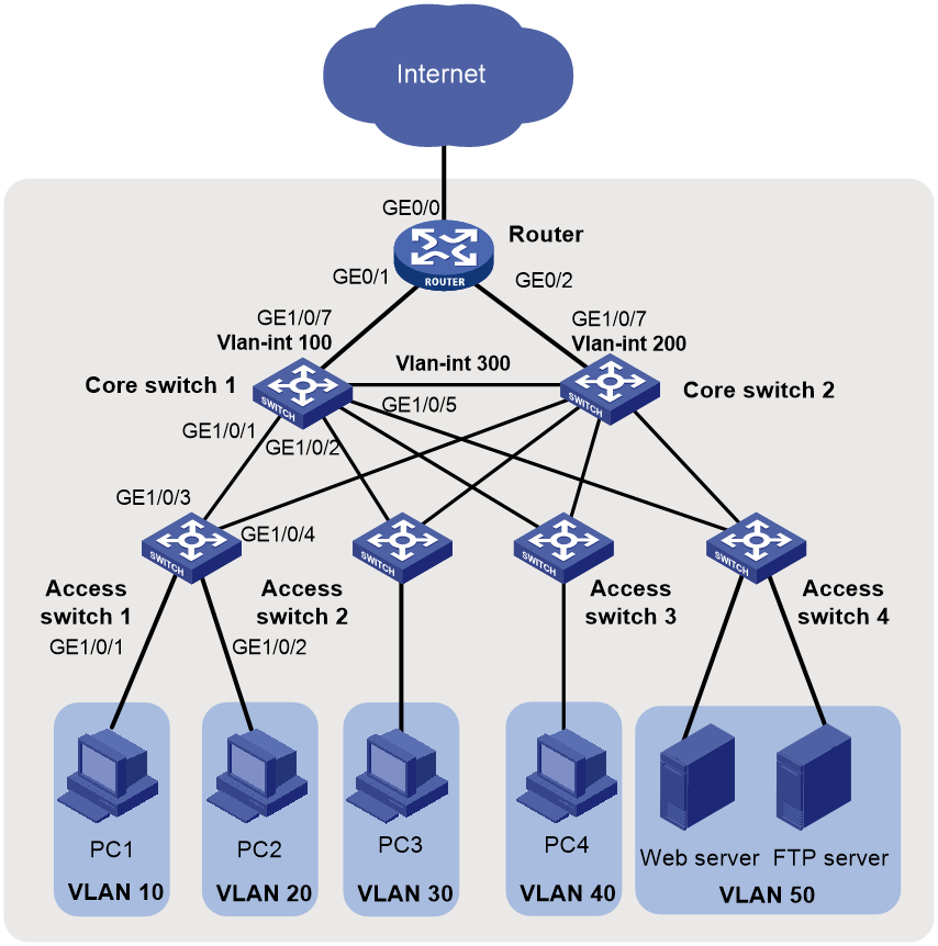
As shown in Figure 1, in a small- to medium-sized campus network, the S5130 or S5130S Ethernet switches series are deployed on the access layer. The S5560X or S6520X Ethernet switches series are deployed on the core layer, and an MSR series router is used as the egress router.
Configure the devices to meet the following requirements:
· Configure VRRP on the core switches to provide high availability.
· Configure VLANs to accommodate services of different departments and configure VLAN interfaces on the core switches to provide Layer 3 connectivity for inter-department services.
· Configure the core switches as the DHCP servers to dynamically assign IP addresses to campus users.
· Enable DHCP snooping on the access switches to prevent unauthorized DHCP servers from assigning IP addresses to intranet users. Additionally, enable IPSG to prevent intranet users from changing their IP addresses.
· Configure per-IP address rate liming on the egress router to limit the rate of incoming and outgoing traffic.
Figure 3 Small- to medium-sized campus network diagram
Analysis and data preparation
Table 2 shows the procedure of deploying a small-l to medium-sized campus network.
Table 2 Procedure of deploying a small- to medium-sized campus network
|
Step |
Item |
Configuration data |
Remarks |
|
1. Log in to the devices. |
Console login |
Communication parameters (the transmission rate, for example). |
Use a PC to log in to the devices through a terminal emulation program. |
|
2. Configure the management IP and Telnet login. |
Management VLAN |
VLAN 5 |
VLAN 1 is the default VLAN. Do not configure VLAN 1 as the management VLAN. This example uses VLAN 5 as the management VLAN. |
|
IP address of the management Ethernet interface or management VLAN interface |
10.10.1.1/24 |
This example uses ACCSW1. For a switch that has a management Ethernet interface, use the IP address of M-GigabitEthernet 0/0/0 for device login. For a switch that does not have a management Ethernet interface, use the IP address of the management VLAN interface for device login. |
|
|
3. Configure interfaces and VLANs. |
Port link type |
· Port connected to a PC: Access or hybrid port · Port connected to a switch: Trunk or hybrid port |
N/A |
|
VLAN IDs |
· Access switch 1: VLANs 10 and 20 · Core switch: VLANs 10, 20, 30, 40, 50, 100, and 300 |
To isolate Department A and Department B at Layer 2, configure VLAN 10 for Department A and VLAN 20 for Department B. The core switch connects to the egress router through VLAN-interface 100. |
|
|
4. Configure the DHCP server on the core switches. |
DHCP server |
Core switch 1 Core switch 2 |
Configure the DHCP server feature on core switch 1 and core switch 2. |
|
DHCP address pools |
· VLAN 10: DHCP address pool 1 · VLAN 20: DHCP address pool 2 |
PCs in Department A and Department B obtain IP addresses from DHCP address pool 1 and DHCP address pool 2, respectively. |
|
|
5. Configure routes on the core switches. |
IP addresses |
Core switch 1: · VLAN-interface 10: 192.168.10.1/24 · VLAN-interface 20: 192.168.20.1/24 · VLAN-interface 100: 172.16.1.1/24 · VLAN-interface 300: 172.16.3.1/24 |
VLAN-interface100 is used for the communication between core switch 1 and the egress router. VLAN-interface 300 is used for the communication between core switch 1 and core switch 2. Assign IP addresses to VLAN-interface 10 and VLAN-interface 20 to allow Department A and Department B to visit each other. |
|
6. Configure the egress router. |
IP address of the public network interface |
GE0/0: 202.101.100.2/30 |
GE0/0 on the egress router is the public network interface that connects the router to the Internet. |
|
Public network gateway address |
202.101.100.1/30 |
The egress router communicates with the service provider device through the public network gateway address. To forward intranet packets to the external network, you must configure a default route with the next hop as the public network gateway address. |
|
|
DNS server address |
202.101.100.199 |
The DNS server translates domain names into IP addresses. |
|
|
IP addresses of the internal network interfaces |
GE0/1: 172.16.1.2/24 GE0/2: 172.16.2.2/24 |
GE0/1 and GE0/2 on the egress router are used for connection between the egress router and the intranet. The egress router connects to the master device and the backup device through GE0/1 and GE0/2, respectively. |
|
|
7. Configure DHCP snooping and IP source guard on the access switches. |
Trusted ports |
GE1/0/1 GE1/0/2 |
A trusted port can forward DHCP messages correctly to ensure that the clients get IP addresses from authorized DHCP servers. |
Procedure
Configuring the access switches
The procedure of configuring access switch 1 is the same as the procedure of configuring access switches 2, 3, and 4. This section uses access switch 1 as an example.
1. Log in to the device through the console port (first device access):
# Shut down the PC from which you will log in to the device.
The serial ports on PCs do not support hot swapping. Before connecting a cable to or disconnecting a cable from a serial port on a PC, you must shut down the PC.
# Use the console cable shipped with the device to connect the PC to the console port of the device. Plug the DB-9 connector of the console cable into the 9-pin serial port of the PC, and then plug the RJ-45 connector into the console port of the device.
|
|
TIP: · Identify interfaces correctly to avoid connection errors. · To connect the PC to the device, first plug the DB-9 connector of the console cable into the 9-pin serial port of the PC, and then plug the RJ-45 connector of the console cable into the console port of the device. · To disconnect the PC from the device, first unplug the RJ-45 connector and then the DB-9 connector. |
Figure 4 Connecting a PC to the console port of the device

# Power on the PC, launch a terminal emulation program, and create a connection that uses the console port connected to the device. Set the port properties as follows:
¡ Bits per second—9600 bps.
¡ Data bits—8.
¡ Stop bits—1.
¡ Parity—None.
¡ Flow control—None.
# Power on the device and press Enter as prompted to enter the CLI.
# (Optional.) Configure the authentication mode for console login.
By default, authentication is disabled for console login. You can log in to the device without entering a username or password. To improve security, configure the authentication mode for console login after you log in to the device for the first time. For more information about authentication modes for console login, see login management configuration in Fundamental Configuration Guide.
2. Configure IP addresses and Telnet login:
# Create VLAN 5, and assign Ten-GigabitEthernet 1/0/10 (the port connected to the PC used for device login) to VLAN 5.
<Sysname> system-view
System View: return to User View with Ctrl+Z.
[Sysname] sysname ACCSW1
[ACCSW1] vlan 5
[ACCSW1-vlan5] port ten-gigabitethernet 1/0/10
[ACCSW1-vlan5] quit
# Create VLAN-interface 5, and assign IP address 10.10.1.1/24 to it.
[ACCSW1] interface vlan-interface 5
[ACCSW1-Vlan-interface5] ip address 10.10.1.1 24
[ACCSW1-Vlan-interface5] quit
# Enable the Telnet service.
[ACCSW1] telnet server enable
# Enable scheme authentication for Telnet login.
[ACCSW1] line vty 0 63
[ACCSW1-line-vty0-63] authentication-mode scheme
[ACCSW1-line-vty0-63] quit
# Create local user admin. Set the password to admin, the service type to Telnet, and the user role to network-admin.
[ACCSW1] local-user admin
New local user added.
[ACCSW1-luser-manage-admin] password simple hello12345
[ACCSW1-luser-manage-admin] authorization-attribute user-role network-admin
[ACCSW1-luser-manage-admin] service-type telnet
[ACCSW1-luser-manage-admin] quit
# Telnet to the device from the PC by using the local user account admin.
The output varies by device model and software version. This example uses an S5560X-30C-PWR-EI switch running Release 1118P07.
C:\Users\Administrator> telnet 10.10.1.1
******************************************************************************
* Copyright (c) 2004-2019 New H3C Technologies Co., Ltd. All rights reserved.*
* Without the owner's prior written consent, *
* no decompiling or reverse-engineering shall be allowed. *
******************************************************************************
login: admin
Password:
<ACCSW1>
The output shows that you have Telneted to the device successfully.
3. Configure interfaces and VLANs:
# Create VLAN 10 and VLAN 20.
[ACCSW1] vlan 10 20
# Configure GigabitEthernet 1/0/1 (the port connected to PC 1) as an access port, assign it to VLAN 10, and configure it as an edge port.
[ACCSW1] interface gigabitethernet 1/0/1
[ACCSW1-GigabitEthernet1/0/1] port link-type access
[ACCSW1-GigabitEthernet1/0/1] port access vlan 10
[ACCSW1-GigabitEthernet1/0/1] stp edged-port
[ACCSW1-GigabitEthernet1/0/1] quit
# Configure GigabitEthernet 1/0/2 (the port connected to PC 2) as an access port, assign it to VLAN 20, and configure it as an edge port.
[ACCSW1] interface gigabitethernet 1/0/2
[ACCSW1-GigabitEthernet1/0/2] port link-type access
[ACCSW1-GigabitEthernet1/0/2] port access vlan 20
[ACCSW1-GigabitEthernet1/0/2] stp edged-port
[ACCSW1-GigabitEthernet1/0/2] quit
# Configure GigabitEthernet 1/0/3 as a trunk port, and assign it to VLAN 10 and VLAN 20.
[ACCSW1] interface gigabitethernet 1/0/3
[ACCSW1-GigabitEthernet1/0/3] port link-type trunk
[ACCSW1-GigabitEthernet1/0/3] port trunk permit vlan 10 20
[ACCSW1-GigabitEthernet1/0/3] quit
# Configure GigabitEthernet 1/0/4 as a trunk port, and assign it to VLAN 10 and VLAN 20.
[ACCSW1] interface gigabitethernet 1/0/4
[ACCSW1-GigabitEthernet1/0/4] port link-type trunk
[ACCSW1-GigabitEthernet1/0/4] port trunk permit vlan 10 20
[ACCSW1-GigabitEthernet1/0/4] quit
# Display information about VLAN 10.
[ACCSW1] display vlan 10
VLAN ID: 10
VLAN type: Static
Route interface: Not configured
Description: VLAN 0010
Name: VLAN 0010
Tagged ports:
GigabitEthernet1/0/3
GigabitEthernet1/0/4
Untagged ports:
GigabitEthernet1/0/1
# Display information about VLAN 20.
[ACCSW1] display vlan 20
VLAN ID: 20
VLAN type: Static
Route interface: Not configured
Description: VLAN 0020
Name: VLAN 0020
Tagged ports:
GigabitEthernet1/0/3
GigabitEthernet1/0/4
Untagged ports:
GigabitEthernet1/0/2
4. Enable BPDU guard globally.
[ACCSW1] stp bpdu-protection
5. Configure DHCP snooping:
# Enable DHCP snooping.
[ACCSW1] dhcp snooping enable
# Configure GigabitEthernet 1/0/3 as a trusted port.
[ACCSW1] interface gigabitethernet 1/0/3
[ACCSW1-GigabitEthernet1/0/3] dhcp snooping trust
[ACCSW1-GigabitEthernet1/0/3] quit
6. Configure IPSG:
# Enable IPv4SG on GigabitEthernet 1/0/1 and verify the source IPv4 address and MAC address for dynamic IPSG, and enable recording of client information in DHCP snooping entries on the interface.
[ACCSW1] interface gigabitethernet 1/0/1
[ACCSW1-GigabitEthernet1/0/1] ip verify source ip-address mac-address
[ACCSW1-GigabitEthernet1/0/1] dhcp snooping binding record
[ACCSW1-GigabitEthernet1/0/1] quit
# Enable IPv4SG on GigabitEthernet 1/0/2 and verify the source IPv4 address and MAC address for dynamic IPSG, and enable recording of client information in DHCP snooping entries on the interface.
[ACCSW1] interface gigabitethernet 1/0/2
[ACCSW1-GigabitEthernet1/0/2] ip verify source ip-address mac-address
[ACCSW1-GigabitEthernet1/0/2] dhcp snooping binding record
[ACCSW1-GigabitEthernet1/0/2] quit
7. Save the configuration:
# Save the running configuration on the access switches. This example uses access switch 1.
[ACCSW1] save
The current configuration will be written to the device. Are you sure? [Y/N]:y
Please input the file name(*.cfg)[flash:/startup.cfg]
(To leave the existing filename unchanged, press the enter key):
flash:/startup.cfg exists, overwrite? [Y/N]:y
Validating file. Please wait...
Saved the current configuration to mainboard device successfully.
Configuring the core switches
The procedure of configuring core switch 1 is similar to the procedure of configuring core switch 2. This section uses core switch 1 as an example. Unless otherwise stated, the configuration of core switch 2 is the same as that of core switch 1.
1. Configure interfaces and VLANs:
# Create VLAN 10, VLAN 20, VLAN 30, VLAN 40, VLAN 50, VLAN 100, and VLAN 300.
<Sysname> system-view
[Sysname] sysname CORESW1
[CORESW1] vlan 10 20 30 40 50 100 300
# Configure GigabitEthernet 1/0/1 as a trunk port, and assign it to VLAN 10 and VLAN 20.
[CORESW1] interface gigabitethernet 1/0/1
[CORESW1-GigabitEthernet1/0/1] port link-type trunk
[CORESW1-GigabitEthernet1/0/1] port trunk permit vlan 10 20
[CORESW1-GigabitEthernet1/0/1] quit
# Configure GigabitEthernet 1/0/5 as a trunk port, and assign it to VLAN 300.
[CORESW1] interface gigabitethernet 1/0/5
[CORESW1-GigabitEthernet1/0/5] port link-type trunk
[CORESW1-GigabitEthernet1/0/5] port trunk permit vlan 300
[CORESW1-GigabitEthernet1/0/5] quit
# Configure the link type and permit VLANs for other interfaces in a similar way. (Details not shown.)
2. Configure VLAN interfaces:
# Create VLAN-interface 10, and assign IP address 192.168.10.1/24 to it.
[CORESW1] interface vlan-interface 10
[CORESW1-Vlan-interface10]ip address 192.168.10.1 24
[CORESW1-Vlan-interface10] quit
# Create VLAN-interface 20, and assign IP address 92.168.20.1/24 to it.
[CORESW1] interface vlan-interface 20
[CORESW1-Vlan-interface20]ip address 192.168.20.1 24
[CORESW1-Vlan-interface20] quit
# Create VLAN-interface 100, and assign IP address 172.16.1.1/24 to it.
[CORESW1] interface vlan-interface 100
[CORESW1-Vlan-interface100]ip address 172.16.1.1 24
[CORESW1-Vlan-interface100] quit
# Create VLAN-interface 300, and assign IP address 172.16.3.1/24 to it.
[CORESW1] interface vlan-interface 300
[CORESW1-Vlan-interface300]ip address 172.16.3.1 24
[CORESW1-Vlan-interface300] quit
# Create other VLAN interfaces and assign IP addresses to them in a similar way. (Details not shown.)
# Display information about VLAN 10.
[CORESW1] display vlan 10
VLAN ID: 10
VLAN type: Static
Route interface: Configured
IPv4 address: 192.168.10.1
IPv4 subnet mask: 255.255.255.0
Description: VLAN 0010
Name: VLAN 0010
Tagged ports:
GigabitEthernet1/0/1
Untagged ports: None
# Display information about VLAN 20.
[CORESW1] display vlan 20
VLAN ID: 20
VLAN type: Static
Route interface: Configured
IPv4 address: 192.168.20.1
IPv4 subnet mask: 255.255.255.0
Description: VLAN 0020
Name: VLAN 0020
Tagged ports:
GigabitEthernet1/0/2
Untagged ports: None
# Display information about VLAN 100.
[CORESW1] display vlan 100
VLAN ID: 100
VLAN type: Static
Route interface: Configured
IPv4 address: 172.16.1.1
IPv4 subnet mask: 255.255.255.0
Description: VLAN 0100
Name: VLAN 0100
Tagged ports: None
Untagged ports: None
# Display information about VLAN 300.
[CORESW1] display vlan 300
VLAN ID: 300
VLAN type: Static
Route interface: Configured
IPv4 address: 172.16.3.1
IPv4 subnet mask: 255.255.255.0
Description: VLAN 0300
Name: VLAN 0300
Tagged ports:
GigabitEthernet1/0/5
Untagged ports: None
3. Configure VRRP:
Use core switch 1 and core switch 2 to form a VRRP group. Core switch 1 operates as the master to process intranet packets. When core switch 1 fails or the upstream link of core switch 1 fails, core switch 2 takes over to process intranet packets.
# On core switch 1, create VRRP group 1 and set its virtual IP address to 172.16.3.10.
[CORESW1] interface vlan-interface 300
[CORESW1-Vlan-interface300] vrrp vrid 1 virtual-ip 172.16.3.10
# Assign core switch 1 a higher priority than core switch 2 in VRRP group 1, so core switch 1 can become the master.
[CORESW1-Vlan-interface300] vrrp vrid 1 priority 120
# Configure core switch 1 to operate in preemptive mode, so it can become the master whenever it operates correctly. Set the preemption delay to 5000 centiseconds to avoid frequent status switchover.
[CORESW1-Vlan-interface300] vrrp vrid 1 preempt-mode delay 5000
[CORESW1-Vlan-interface300] quit
# Create track entry 1 to monitor the upstream link status of GigabitEthernet 1/0/7. When the upstream link fails, the track entry transits to Negative.
[CORESW1] track 1 interface gigabitethernet 1/0/7
[CORESW1-track-1] quit
# Configure the VFs in VRRP group 1 to monitor track entry 1, and decrease their weights by 30 when the track entry transits to Negative.
[CORESW1] interface vlan-interface 300
[CORESW1-Vlan-interface300] vrrp vrid 1 track 1 priority reduced 30
# On core switch 2, create VRRP group 1 and set its virtual IP address to 172.16.3.10.
<Sysname> system-view
[Sysname] sysname CORESW2
[CORESW2] interface vlan-interface 300
[CORESW2-Vlan-interface300] vrrp vrid 1 virtual-ip 172.16.3.10
# Set the priority of core switch 2 to 100 in VRRP group 1.
[CORESW2-Vlan-interface300] vrrp vrid 1 priority 100
# Configure core switch 2 to operate in preemptive mode, and set the preemption delay to 5000 centiseconds.
[CORESW2-Vlan-interface300] vrrp vrid 1 preempt-mode delay 5000
[CORESW2-Vlan-interface300] quit
# Display detailed information about VRRP group 1 on core switch 1.
[CORESW1] display vrrp verbose
IPv4 Virtual Router Information:
Running mode : Standard
Total number of virtual routers : 1
Interface Vlan-interface300
VRID : 1 Adver Timer : 100
Admin Status : Up State : Master
Config Pri : 120 Running Pri : 120
Preempt Mode : Yes Delay Time : 5000
Auth Type : None
Virtual IP : 172.16.3.10
Virtual MAC : 0000-5e00-0101
Master IP : 172.16.3.1
VRRP Track Information:
Track Object : 1 State : Positive Pri Reduced : 30
# Display detailed information about VRRP group 1 on core switch 2.
[CORESW2] display vrrp verbose
IPv4 Virtual Router Information:
Running mode : Standard
Total number of virtual routers : 1
Interface Vlan-interface300
VRID : 1 Adver Timer : 100
Admin Status : Up State : Backup
Config Pri : 100 Running Pri : 100
Preempt Mode : Yes Delay Time : 5000
Become Master : 27810ms left
Auth Type : None
Virtual IP : 172.16.3.10
Virtual MAC : 0000-5e00-0101
Master IP : 172.16.3.1
The output shows that core switch 1 is operating as the master and core switch 2 is operating as the backup in VRRP group 1.
4. Configure the DHCP server feature:
# Enable DHCP.
[CORESW1] dhcp enable
# Create DHCP address pool 1. In this pool, specify network segment 192.168.10.0/24, gateway address 192.168.10.1, DNS server address 202.101.100.199, set the lease duration to 30 days, and bind IP address 192.168.10.254/24 to the printer.
[CORESW1] dhcp server ip-pool 1
[CORESW1-dhcp-pool-1] network 192.168.10.0 mask 255.255.255.0
[CORESW1-dhcp-pool-1] gateway-list 192.168.10.1
[CORESW1-dhcp-pool-1] dns-list 202.101.100.199
[CORESW1-dhcp-pool-1] expired day 30
[CORESW1-dhcp-pool-1] static-bind ip-address 192.168.10.254 24 client-identifier aabb-cccc-dd
[CORESW1-dhcp-pool-1] quit
# Create DHCP address pool 2. In this pool, specify network segment 192.168.20.0/24, gateway address 192.168.20.1, DNS server address 202.101.100.199, and set the lease duration to 30 days.
# Configure DHCP address pool 2 to assign IP addresses and other configuration parameters to clients on subnet 192.168.10.0/24.
[CORESW1] dhcp server ip-pool 2
[CORESW1-dhcp-pool-2] network 192.168.20.0 mask 255.255.255.0
[CORESW1-dhcp-pool-2] gateway-list 192.168.20.1
[CORESW1-dhcp-pool-2] dns-list 202.101.100.199
[CORESW1-dhcp-pool-2] expired day 30
[CORESW1-dhcp-pool-2] quit
# Enable the DHCP server on VLAN-interface 10, and apply DHCP address pool 1 to VLAN-interface 10.
[CORESW1] interface vlan-interface 10
[CORESW1-Vlan-interface10] dhcp select server
[CORESW1-Vlan-interface10] dhcp server apply ip-pool 1
[CORESW1-Vlan-interface10] quit
# Enable the DHCP server on VLAN-interface 20, and apply DHCP address pool 2 to VLAN-interface 10.
[CORESW1 interface vlan-interface 20
[CORESW1-Vlan-interface20] dhcp select server
[CORESW1-Vlan-interface20] dhcp server apply ip-pool 2
[CORESW1-Vlan-interface20] quit
# Display DHCP address pool information.
[CORESW1] display dhcp server pool
Pool name: 1
Network: 192.168.10.0 mask 255.255.255.0
expired 30 0 0 0
gateway-list 192.168.10.1
static bindings:
ip-address 192.168.10.254 mask 255.255.255.0
client-identifier aabb-cccc-dd
Pool name: 2
Network: 192.168.20.0 mask 255.255.255.0
expired 30 0 0 0
gateway-list 192.168.20.1
5. Configure OSPF:
# Configure OSPF on core switch 1.
[CORESW1] ospf 100 router-id 2.2.2.2
[CORESW1-ospf-100] area 0
[CORESW1-ospf-100-area-0.0.0.0] network 172.16.1.0 0.0.0.255
[CORESW1-ospf-100-area-0.0.0.0] network 172.16.3.0 0.0.0.255
[CORESW1-ospf-100-area-0.0.0.0] network 192.168.10.0 0.0.0.255
[CORESW1-ospf-100-area-0.0.0.0] network 192.168.20.0 0.0.0.255
[CORESW1-ospf-100-area-0.0.0.0] quit
[CORESW1-ospf-100] quit
# Configure OSPF on core switch 2.
[CORESW2] ospf 100 router-id 3.3.3.3
[CORESW2-ospf-100] area 0
[CORESW2-ospf-100-area-0.0.0.0] network 172.16.2.0 0.0.0.255
[CORESW2-ospf-100-area-0.0.0.0] network 172.16.3.0 0.0.0.255
[CORESW2-ospf-100-area-0.0.0.0] network 192.168.10.0 0.0.0.255
[CORESW2-ospf-100-area-0.0.0.0] network 192.168.20.0 0.0.0.255
[CORESW2-ospf-100-area-0.0.0.0] quit
[CORESW2-ospf-100] quit
# Display OSPF neighbor information on core switch 1.
[CORESW1] display ospf peer
OSPF Process 100 with Router ID 2.2.2.2
Neighbor Brief Information
Area: 0.0.0.0
Router ID Address Pri Dead-Time State Interface
3.3.3.3 172.16.3.2 1 33 Full/DR Vlan300
# Display OSPF neighbor information on core switch 2.
[CORESW2] display ospf peer
OSPF Process 100 with Router ID 3.3.3.3
Neighbor Brief Information
Area: 0.0.0.0
Router ID Address Pri Dead-Time State Interface
2.2.2.2 172.16.3.1 1 36 Full/BDR Vlan300
6. Save the configuration:
# Save the running configuration on the core switches. This example uses core switch CORESW1.
[CORESW1] save
The current configuration will be written to the device. Are you sure? [Y/N]:y
Please input the file name(*.cfg)[flash:/startup.cfg]
(To leave the existing filename unchanged, press the enter key):
flash:/startup.cfg exists, overwrite? [Y/N]:y
Validating file. Please wait...
Saved the current configuration to mainboard device successfully.
Configuring the egress router
1. Assign IP addresses to the public network interfaces and the internal network interface:
# Assign IP addresses to internet network interfaces.
[Router] interface GigabitEthernet 0/1
[Router-GigabitEthernet0/1] ip address 172.16.1.2 24
[Router-GigabitEthernet0/1] quit
[Router] interface GigabitEthernet 0/2
[Router-GigabitEthernet0/2] ip address 172.16.2.2 24
[Router-GigabitEthernet0/2] quit
# Assign an IP address to the public network interface.
[Router] interface GigabitEthernet 0/0
[Router-GigabitEthernet0/0] ip address 202.101.100.2 30
[Router-GigabitEthernet0/0] quit
2. Configure packet filtering:
# Configure ACL 2000.
[Router] acl basic 2000
[Router-acl-ipv4-basic-2000] rule permit source 192.168.10.0 0.0.0.255
[Router-acl-ipv4-basic-2000] rule permit source 192.168.20.0 0.0.0.255
[Router-acl-ipv4-basic-2000] rule permit source 172.16.1.0 0.0.0.255
[Router-acl-ipv4-basic-2000] rule permit source 172.16.2.0 0.0.0.255
[Router-acl-ipv4-basic-2000] rule permit source 172.16.3.0 0.0.0.255
[Router-acl-ipv4-basic-2000] quit
# Apply ACL 2000 to GigabitEthernet 0/1 and GigabitEthernet 1/0/2 to filter incoming packets.
[Router] interface gigabitethernet 0/1
[Router-GigabitEthernet0/1] packet-filter 2000 inbound
[Router-GigabitEthernet0/1] quit
[Router] interface gigabitethernet 0/2
[Router-GigabitEthernet0/2] packet-filter 2000 inbound
[Router-GigabitEthernet0/2] quit
# Set the packet filtering default action to deny.
[Router] packet-filter default deny
# Display configuration and match statistics for ACL 2000.
[Router] display acl 2000
Basic IPv4 ACL 2000, 5 rules,
ACL's step is 5, start ID is 0
rule 0 permit source 192.168.10.0 0.0.0.255
rule 5 permit source 192.168.20.0 0.0.0.255
rule 10 permit source 172.16.1.0 0.0.0.255
rule 15 permit source 172.16.2.0 0.0.0.255
rule 20 permit source 172.16.3.0 0.0.0.255
# Display ACL application information for inbound packet filtering on GigabitEthernet 0/1.
[Router] display packet-filter interface gigabitethernet 0/1 inbound
Interface: GigabitEthernet0/1
Inbound policy:
IPv4 ACL 2000
# Display ACL application information for inbound packet filtering on GigabitEthernet 0/2.
[Router] display packet-filter interface gigabitethernet 0/2 inbound
Interface: GigabitEthernet0/2
Inbound policy:
IPv4 ACL 2000
3. Configure OSPF:
# Configure a default static route, whose next hop address is 202.101.100.1 (the public network gateway address).
[Router] ip route-static 0.0.0.0 0.0.0.0 202.101.100.1
# Configure OSPF and redistribute a default route into the OSPF routing domain.
[Router] ospf 10 router-id 1.1.1.1
[Router-ospf-10] default-route-advertise always
[Router-ospf-10] area 0
[Router-ospf-10-area-0.0.0.0] network 172.16.1.0 0.0.0.255
[Router-ospf-10-area-0.0.0.0] network 172.16.2.0 0.0.0.255
[Router-ospf-10-area-0.0.0.0] quit
[Router-ospf-10] quit
# Display OSPF neighbor information on the egress router.
[Router] display ospf peer
OSPF Process 100 with Router ID 1.1.1.1
Neighbor Brief Information
Area: 0.0.0.0
Router ID Address Pri Dead-Time State Interface
2.2.2.2 172.16.1.1 1 31 Full/DR GE0/1
3.3.3.3 172.16.2.1 1 39 Full/BDR GE0/2
# Display OSPF neighbor information on core switch 1.
[CORESW1] display ospf routing
OSPF Process 100 with Router ID 2.2.2.2
Routing Table
Topology base (MTID 0)
Routing for network
Destination Cost Type NextHop AdvRouter Area
172.16.1.0/24 1 Transit 0.0.0.0 2.2.2.2 0.0.0.0
172.16.2.0/24 2 Transit 172.16.3.2 1.1.1.1 0.0.0.0
172.16.2.0/24 2 Transit 172.16.1.2 1.1.1.1 0.0.0.0
172.16.3.0/24 1 Transit 0.0.0.0 3.3.3.3 0.0.0.0
Routing for ASEs
Destination Cost Type Tag NextHop AdvRouter
0.0.0.0/0 1 Type2 1 172.16.1.2 1.1.1.1
Total nets: 5
Intra area: 4 Inter area: 0 ASE: 1 NSSA: 0
# Display OSPF neighbor information on core switch 2.
[CORESW2] display ospf routing
OSPF Process 100 with Router ID 3.3.3.3
Routing Table
Topology base (MTID 0)
Routing for network
Destination Cost Type NextHop AdvRouter Area
172.16.1.0/24 2 Transit 172.16.3.1 2.2.2.2 0.0.0.0
172.16.1.0/24 2 Transit 172.16.2.2 2.2.2.2 0.0.0.0
172.16.2.0/24 1 Transit 0.0.0.0 1.1.1.1 0.0.0.0
172.16.3.0/24 1 Transit 0.0.0.0 3.3.3.3 0.0.0.0
Routing for ASEs
Destination Cost Type Tag NextHop AdvRouter
0.0.0.0/0 1 Type2 1 172.16.2.2 1.1.1.1
Total nets: 5
Intra area: 4 Inter area: 0 ASE: 1 NSSA: 0
4. Configure DNS:
# Specify DNS server IPv4 address 202.101.100.199.
[Router] dns server 202.101.100.199
# Enable DNS proxy.
[Router] dns proxy enable
5. Configure per-IP-address rate limiting:
# Configure CAR lists.
[Router] qos carl 1 source-ip-address range 192.168.10.1 to 192.168.10.254 per-address shared-bandwidth
[Router] qos carl 2 source-ip-address range 192.168.20.1 to 192.168.20.254 per-address shared-bandwidth
[Router] qos carl 3 destination-ip-address range 192.168.10.1 to 192.168.10.254 per-address shared-bandwidth
[Router] qos carl 4 destination-ip-address range 192.168.20.1 to 192.168.20.254 per-address shared-bandwidth
# Configure CAR-list-based traffic policing.
[Router] interface gigabitethernet 0/1
[Router-GigabitEthernet0/1] qos car inbound carl 1 cir 512
[Router-GigabitEthernet0/1] qos car inbound carl 2 cir 512
[Router-GigabitEthernet0/1] qos car outbound carl 3 cir 512
[Router-GigabitEthernet0/1] qos car outbound carl 4 cir 512
[Router-GigabitEthernet0/1] quit
[Router] interface gigabitethernet 0/2
[Router-GigabitEthernet0/2] qos car inbound carl 1 cir 512
[Router-GigabitEthernet0/2] qos car inbound carl 2 cir 512
[Router-GigabitEthernet0/2] qos car outbound carl 3 cir 512
[Router-GigabitEthernet0/2] qos car outbound carl 4 cir 512
[Router-GigabitEthernet0/2] quit
# Display CAR list information.
[Router] display qos carl
List Rules
1 source-ip-address range 192.168.10.1 to 192.168.10.254 per-address shared-bandwidth
2 source-ip-address range 192.168.20.1 to 192.168.20.254 per-address shared-bandwidth
3 destination-ip-address range 192.168.10.1 to 192.168.10.254 per-address shared-bandwidth
4 destination-ip-address range 192.168.20.1 to 192.168.20.254 per-address shared-bandwidth
# Display CAR configuration and statistics on GigabitEthernet 0/1.
[Router] display qos car interface gigabitethernet 0/1
Interface: GigabitEthernet0/1
Direction: inbound
Rule: If-match carl 1
CIR 512 (kbps), CBS 32000 (Bytes), EBS 0 (Bytes)
Green action : pass
Yellow action : pass
Red action : discard
Green packets : 0 (Packets), 0 (Bytes)
Yellow packets: 0 (Packets), 0 (Bytes)
Red packets : 0 (Packets), 0 (Bytes)
Rule: If-match carl 2
CIR 512 (kbps), CBS 32000 (Bytes), EBS 0 (Bytes)
Green action : pass
Yellow action : pass
Red action : discard
Green packets : 0 (Packets), 0 (Bytes)
Yellow packets: 0 (Packets), 0 (Bytes)
Red packets : 0 (Packets), 0 (Bytes)
Direction: outbound
Rule: If-match carl 3
CIR 512 (kbps), CBS 32000 (Bytes), EBS 0 (Bytes)
Green action : pass
Yellow action : pass
Red action : discard
Green packets : 0 (Packets), 0 (Bytes)
Yellow packets: 0 (Packets), 0 (Bytes)
Red packets : 0 (Packets), 0 (Bytes)
Rule: If-match carl 4
CIR 512 (kbps), CBS 32000 (Bytes), EBS 0 (Bytes)
Green action : pass
Yellow action : pass
Red action : discard
Green packets : 0 (Packets), 0 (Bytes)
Yellow packets: 0 (Packets), 0 (Bytes)
Red packets : 0 (Packets), 0 (Bytes)
# Display CAR configuration and statistics on GigabitEthernet 0/2.
[Router] display qos car interface gigabitethernet 0/2
Interface: GigabitEthernet0/2
Direction: inbound
Rule: If-match carl 1
CIR 512 (kbps), CBS 32000 (Bytes), EBS 0 (Bytes)
Green action : pass
Yellow action : pass
Red action : discard
Green packets : 0 (Packets), 0 (Bytes)
Yellow packets: 0 (Packets), 0 (Bytes)
Red packets : 0 (Packets), 0 (Bytes)
Rule: If-match carl 2
CIR 512 (kbps), CBS 32000 (Bytes), EBS 0 (Bytes)
Green action : pass
Yellow action : pass
Red action : discard
Green packets : 0 (Packets), 0 (Bytes)
Yellow packets: 0 (Packets), 0 (Bytes)
Red packets : 0 (Packets), 0 (Bytes)
Direction: outbound
Rule: If-match carl 3
CIR 512 (kbps), CBS 32000 (Bytes), EBS 0 (Bytes)
Green action : pass
Yellow action : pass
Red action : discard
Green packets : 0 (Packets), 0 (Bytes)
Yellow packets: 0 (Packets), 0 (Bytes)
Red packets : 0 (Packets), 0 (Bytes)
Rule: If-match carl 4
CIR 512 (kbps), CBS 32000 (Bytes), EBS 0 (Bytes)
Green action : pass
Yellow action : pass
Red action : discard
Green packets : 0 (Packets), 0 (Bytes)
Yellow packets: 0 (Packets), 0 (Bytes)
Red packets : 0 (Packets), 0 (Bytes)
6. Save the configuration:
# Save the running configuration on the egress router.
[Router] save
The current configuration will be written to the device. Are you sure? [Y/N]:y
Please input the file name(*.cfg)[flash:/startup.cfg]
(To leave the existing filename unchanged, press the enter key):
flash:/startup.cfg exists, overwrite? [Y/N]:y
Validating file. Please wait...
Saved the current configuration to mainboard device successfully.
Verifying the configuration
1. Verify that two PCs in the same department can ping each other.
# Use PC 1 in VLAN 10 to ping another PC in this VLAN.
<PC1> ping 192.168.10.83
Ping 192.168.10.83 (192.168.10.83): 56 data bytes, press CTRL+C to break
56 bytes from 192.168.10.83: icmp_seq=0 ttl=255 time=1.328 ms
56 bytes from 192.168.10.83: icmp_seq=1 ttl=255 time=0.808 ms
56 bytes from 192.168.10.83: icmp_seq=2 ttl=255 time=0.832 ms
56 bytes from 192.168.10.83: icmp_seq=3 ttl=255 time=0.904 ms
56 bytes from 192.168.10.83: icmp_seq=4 ttl=255 time=0.787 ms
--- Ping statistics for 192.168.10.83 ---
5 packet(s) transmitted, 5 packet(s) received, 0.0% packet loss
round-trip min/avg/max/std-dev = 0.787/0.932/1.328/0.202 ms
2. Verify that two PCs in different departments can ping each other.
# Use PC 1 in VLAN 10 to ping a PC in a different VLAN.
<PC1> ping 192.168.20.5
Ping 192.168.20.5 (192.168.20.5): 56 data bytes, press CTRL+C to break
56 bytes from 192.168.20.5: icmp_seq=0 ttl=255 time=69.146 ms
56 bytes from 192.168.20.5: icmp_seq=1 ttl=255 time=1.735 ms
56 bytes from 192.168.20.5: icmp_seq=2 ttl=255 time=1.356 ms
56 bytes from 192.168.20.5: icmp_seq=3 ttl=255 time=1.302 ms
56 bytes from 192.168.20.5: icmp_seq=4 ttl=255 time=1.379 ms
--- Ping statistics for 192.168.20.5 ---
5 packet(s) transmitted, 5 packet(s) received, 0.0% packet loss
round-trip min/avg/max/std-dev = 1.302/14.984/69.146/27.082 ms
3. Verify that a PC in each department can ping the external network.
# Use PC 1 in VLAN 10 to ping the public network gateway address. (Details not shown.)
Configuration files
Access switch ACCSW1
#
sysname ACCSW1
#
telnet server enable
#
dhcp snooping enable
#
vlan 5
#
vlan 10
#
vlan 20
#
stp bpdu-protection
#
interface Vlan-interface5
ip address 10.10.1.1 255.255.255.0
#
interface GigabitEthernet1/0/1
port link-mode bridge
port access vlan 10
stp edged-port
ip verify source ip-address mac-address
dhcp snooping binding record
#
interface GigabitEthernet1/0/2
port link-mode bridge
port access vlan 20
stp edged-port
ip verify source ip-address mac-address
dhcp snooping binding record
#
interface GigabitEthernet1/0/3
port link-mode bridge
port link-type trunk
port trunk permit vlan 10 20
dhcp snooping trust
#
interface GigabitEthernet1/0/4
port link-mode bridge
port link-type trunk
port trunk permit vlan 10 20
#
interface Ten-GigabitEthernet1/0/10
port link-mode bridge
port access vlan 5
#
line vty 0 63
authentication-mode scheme
#
local-user admin class manage
password hash $h$6$ZJSf20ub4uEzjy2F$cXW3O3Jt5Ci21ECze7w2MdRpLebMaE4vXBo59frUrIZs+Knxw76oNBu+HiB0zqkTfrnw1Phe0rSRa5d+OSIIbg==
service-type telnet
authorization-attribute user-role network-admin
authorization-attribute user-role network-operator
#
Access switches ACCSW2, ACCSW3, ACCSW4
The configuration files of access switches ACCSW2, ACCSW3, and ACCSW4 are the same as that of ACCSW1 except the VLAN IDs, management VLAN interface address, and interface numbers. (Details not shown.)
Core switch CORESW1
#
sysname CORESW1
#
track 1 interface GigabitEthernet1/0/7
#
ospf 100 router-id 3.3.3.3
area 0.0.0.0
network 172.16.1.0 0.0.0.255
network 172.16.3.0 0.0.0.255
network 192.168.10.0 0.0.0.255
network 192.168.20.0 0.0.0.255
#
dhcp enable
#
vlan 10
#
vlan 20
#
vlan 30
#
vlan 40
#
vlan 50
#
vlan 100
#
vlan 300
#
ftth
#
dhcp server ip-pool 1
gateway-list 192.168.10.1
network 192.168.10.0 mask 255.255.255.0
dns-list 202.101.100.199
expired day 30
static-bind ip-address 192.168.10.254 mask 255.255.255.0 client-identifier aabb-cccc-dd
#
dhcp server ip-pool 2
gateway-list 192.168.20.1
network 192.168.20.0 mask 255.255.255.0
dns-list 202.101.100.199
expired day 30
#
interface Vlan-interface10
ip address 192.168.10.1 255.255.255.0
#
interface Vlan-interface20
ip address 192.168.20.1 255.255.255.0
#
interface Vlan-interface100
ip address 172.16.1.1 255.255.255.0
#
interface Vlan-interface300
ip address 172.16.3.1 255.255.255.0
vrrp vrid 1 virtual-ip 172.16.3.10
vrrp vrid 1 priority 120
vrrp vrid 1 preempt-mode delay 5000
vrrp vrid 1 track 1 priority reduced 30
#
interface GigabitEthernet1/0/1
port link-mode bridge
port link-type trunk
port trunk permit vlan 10
#
interface GigabitEthernet1/0/2
port link-mode bridge
port link-type trunk
port trunk permit vlan 20
#
interface GigabitEthernet1/0/5
port link-mode bridge
port link-type trunk
port trunk permit vlan 300
#
Core switch CORESW2
The configuration file of core switch CORESW2 is the same as that of CORESW1 except the VLAN IDs, interface numbers, OSPF router ID, and VRRP group 1's priority. (Details not shown.)
Egress router
#
sysname Router
#
packet-filter default deny
#
qos carl 1 source-ip-address range 192.168.10.1 to 192.168.10.254 per-address shared-bandwidth
qos carl 2 source-ip-address range 192.168.20.1 to 192.168.20.254 per-address shared-bandwidth
qos carl 3 destination-ip-address range 192.168.10.1 to 192.168.10.254 per-address shared-bandwidth
qos carl 4 destination-ip-address range 192.168.20.1 to 192.168.20.254 per-address shared-bandwidth
#
ospf 10 router-id 1.1.1.1
default-route-advertise always
area 0.0.0.0
network 172.16.1.0 0.0.0.255
network 172.16.2.0 0.0.0.255
#
dns proxy enable
dns server 202.101.100.199
#
interface GigabitEthernet0/1
port link-mode route
ip address 172.16.1.2 255.255.255.0
packet-filter 2000 inbound
qos car inbound carl 1 cir 512 cbs 32000 ebs 0 green pass red discard yellow pass
qos car inbound carl 2 cir 512 cbs 32000 ebs 0 green pass red discard yellow pass
qos car outbound carl 3 cir 512 cbs 32000 ebs 0 green pass red discard yellow pass
qos car outbound carl 4 cir 512 cbs 32000 ebs 0 green pass red discard yellow pass
#
interface GigabitEthernet0/2
port link-mode route
ip address 172.16.2.2 255.255.255.0
packet-filter 2000 inbound
qos car inbound carl 1 cir 512 cbs 32000 ebs 0 green pass red discard yellow pass
qos car inbound carl 2 cir 512 cbs 32000 ebs 0 green pass red discard yellow pass
qos car outbound carl 3 cir 512 cbs 32000 ebs 0 green pass red discard yellow pass
qos car outbound carl 4 cir 512 cbs 32000 ebs 0 green pass red discard yellow pass
#
interface GigabitEthernet0/0
port link-mode route
ip address 202.101.100.2 255.255.255.252
#
ip route-static 0.0.0.0 0 202.101.100.1
#
acl basic 2000
rule 0 permit source 192.168.10.0 0.0.0.255
rule 5 permit source 192.168.20.0 0.0.0.255
rule 10 permit source 172.16.1.0 0.0.0.255
rule 15 permit source 172.16.2.0 0.0.0.255
rule 20 permit source 172.16.3.0 0.0.0.255
#
Related documentation
· Login management configuration in the fundamentals configuration guide for the device.
· Login management commands in the fundamentals command reference for the device.
· VLAN configuration in the Layer 2—LAN switching configuration guide for the device.
· VLAN commands in the Layer 2—LAN switching command reference for the device.
· Ethernet link aggregation configuration in the Layer 2—LAN switching configuration guide for the device.
· Ethernet link aggregation commands in the Layer 2—LAN switching command reference for the device.
· DHCP configuration in the Layer 3—IP services configuration guide for the device.
· DHCP commands in the Layer 3—IP services command reference for the device.
· OSPF configuration in the Layer 3—IP routing configuration guide for the device.
· OSPF commands in the Layer 3—IP routing command reference for the device.
· ACL configuration in the ACL and QoS configuration guide for the device.
· ACL commands in the ACL and QoS command reference for the device.
· QoS configuration in the ACL and QoS configuration guide for the device.
· QoS commands in the ACL and QoS command reference for the device.
· IP source guard configuration in the security configuration guide for the device.
· IP source guard commands in the security command reference for the device.