- Table of Contents
-
- H3C Campus Fixed-Port Switches CLI-Based Quick Start Configuration Guide-6W101
- 01-H3C Devices CLI Reference
- 02-Login Management Quick Start Configuration Guide
- 03-Configuration File Management Quick Start Configruation Guide
- 04-Software Upgrade Quick Start Configuration Guide
- 05-Device Management Quick Start Configuration Guide
- 06-NTP Quick Start Configuration Guide
- 07-RBAC Quick Start Configuration Guide
- 08-IRF Quick Start Configuration Guide
- 09-Ethernet Interface Quick Start Configuration Guide
- 10-VLAN Quick Start Configuration Guide
- 11-Port Isolation Quick Start Configuration Guide
- 12-Loop Detection Quick Start Configuration Guide
- 13-QinQ Quick Start Configuration Guide
- 14-MAC Address Table Quick Start Configuration Guide
- 15-Ethernet Link Aggregation Quick Start Configuration Guide
- 16-Spanning Tree Quick Start Configuration Guide
- 17-DHCP Quick Start Configuration Guide
- 18-OSPF Quick Start Configuration Guide
- 19-Static Routing Quick Start Configuration Guide
- 20-Basic RIP Quick Start Configuration Guide
- 21-PBR Quick Start Configuration Guide
- 22-IGMP Snooping Quick Start Configuration Guide
- 23-Packet Filtering Quick Start Configuration Guide
- 24-QoS Quick Start Configuration Guide
- 25-IP Source Guard Quick Start Configuration Guide
- 26-SSH Quick Start Configuration Guide
- 27-Port Security Quick Start Configuration Guide
- 28-VRRP Quick Start Configuration Guide
- 29-PoE Quick Start Configuration Guide
- 30-Mirroring Quick Start Configuration Guide
- 31-Information Center Quick Start Configuration Guide
- 32-SNMP Quick Start Configuration Guide
- 33-LAN Networks Quick Start Configuration Guide
- Related Documents
-
| Title | Size | Download |
|---|---|---|
| 16-Spanning Tree Quick Start Configuration Guide | 83.58 KB |
Spanning Tree Quick Start Configuration Guide
Copyright © 2022 New H3C Technologies Co., Ltd. All rights reserved.
No part of this manual may be reproduced or transmitted in any form or by any means without prior written consent of New H3C Technologies Co., Ltd.
Except for the trademarks of New H3C Technologies Co., Ltd., any trademarks that may be mentioned in this document are the property of their respective owners.
The information in this document is subject to change without notice.
Contents
Configuring MSTP
Introduction
The following information uses an example to describe the basic procedure for configuring MSTP.
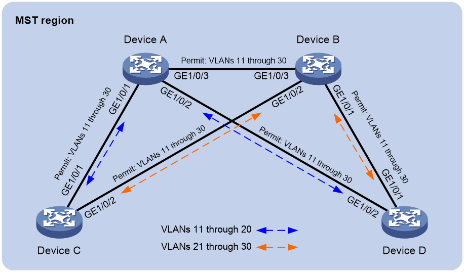
Network configuration
As shown in Figure 1, Device A and Device B operate at the core layer, and Device C and Device D operate at the distribution layer. The ports on the devices have the same path cost, and they all permit VLANs 11 through 30.
Configure MSTP to meet the following requirements:
· Device A, Device B, Device C, and Device D belong to the same MST region.
· MSTIs are used to share the traffic of VLANs 11 through 20 and of VLANs 21 through 30.
Analysis
To assign the devices to the same MST region, make sure the following MST region parameters are the same on the devices:
· Spanning tree mode (the default mode MSTP is used).
· Region name (test in this example).
· Revision level (the default value 0 is used).
· VLAN-to-instance mappings (VLANs 11 through 20 to MSTI 1, and VLANs 21 through 30 to MSTI 2).
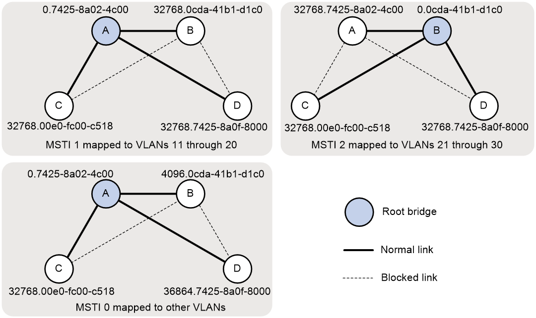
To use redundant links to share the traffic of different VLANs (as shown in Figure 2), perform the following tasks:
· Configure Device A as the root bridge of MSTI 1.
· Configure Device B as the root bridge of MIST 2.
· Assign priorities to Device A, Device B, Device C, and Device D in MSTI 0 in descending order for Device A to be the regional root bridge.
Figure 2 MSTIs mapped to different VLANs
Procedure
Configuring Device A
# Create VLANs 11 through 30.
<DeviceA> system-view
[DeviceA] vlan 11 to 30
# Configure GigabitEthernet 1/0/1, GigabitEthernet 1/0/2, and GigabitEthernet 1/0/3 to trunk VLANs 11 through 30.
[DeviceA] interface range gigabitethernet 1/0/1 to gigabitethernet 1/0/3
[DeviceA-if-range] port link-type trunk
[DeviceA-if-range] port trunk permit vlan 11 to 30
[DeviceA-if-range] quit
# Configure the MST region name as test.
[DeviceA] stp region-configuration
[DeviceA-mst-region] region-name test
# Map VLANs 11 through 20 to MSTI 1, and map VLANs 21 through 30 to MSTI 2.
[DeviceA-mst-region] instance 1 vlan 11 to 20
[DeviceA-mst-region] instance 2 vlan 21 to 30
# Activate the MST region configuration.
[DeviceA-mst-region] active region-configuration
[DeviceA-mst-region] quit
# Configure Device A as the root bridge of MSTI 0 and MSTI 1.
[DeviceA] stp instance 0 to 1 root primary
# Enable the spanning tree feature globally.
[DeviceA] stp global enable
# Save the configuration.
[DeviceA] save force
Configuring Device B
# Create VLANs 11 through 30.
<DeviceB> system-view
[DeviceB] vlan 11 to 30
# Configure GigabitEthernet 1/0/1, GigabitEthernet 1/0/2, and GigabitEthernet 1/0/3 to trunk VLANs 11 through 30.
[DeviceB] interface range gigabitethernet 1/0/1 to gigabitethernet 1/0/3
[DeviceB-if-range] port link-type trunk
[DeviceB-if-range] port trunk permit vlan 11 to 30
[DeviceB-if-range] quit
# Configure the MST region name as test.
[DeviceB] stp region-configuration
[DeviceB-mst-region] region-name test
# Map VLANs 11 through 20 to MSTI 1, and map VLANs 21 through 30 to MSTI 2.
[DeviceB-mst-region] instance 1 vlan 11 to 20
[DeviceB-mst-region] instance 2 vlan 21 to 30
# Activate the MST region configuration.
[DeviceB-mst-region] active region-configuration
[DeviceB-mst-region] quit
# Configure Device B as the root bridge of MSTI 2 and a secondary root bridge of MSTI 0.
[DeviceB] stp instance 2 root primary
[DeviceB] stp instance 0 root secondary
# Enable the spanning tree feature globally.
[DeviceB] stp global enable
# Save the configuration.
[DeviceB] save force
Configuring Device C
# Create VLANs 11 through 30.
<DeviceC> system-view
[DeviceC] vlan 11 to 30
# Configure GigabitEthernet 1/0/1 and GigabitEthernet 1/0/2 to trunk VLANs 11 through 30.
[DeviceC] interface range gigabitethernet 1/0/1 to gigabitethernet 1/0/2
[DeviceC-if-range] port link-type trunk
[DeviceC-if-range] port trunk permit vlan 11 to 30
[DeviceC-if-range] quit
# Configure the MST region name as test.
[DeviceC] stp region-configuration
[DeviceC-mst-region] region-name test
# Map VLANs 11 through 20 through MSTI 1, and map VLANs 21 through 30 to MSTI 2.
[DeviceC-mst-region] instance 1 vlan 11 to 20
[DeviceC-mst-region] instance 2 vlan 21 to 30
# Activate the MST region configuration.
[DeviceC-mst-region] active region-configuration
[DeviceC-mst-region] quit
# Enable the spanning tree feature globally.
[DeviceC] stp global enable
# Save the configuration.
[DeviceC] save force
Configuring Device D
# Create VLANs 11 through 30.
<DeviceD> system-view
[DeviceD] vlan 11 to 30
# Configure GigabitEthernet 1/0/1 and GigabitEthernet 1/0/2 to trunk VLANs 11 through 30.
[DeviceD] interface range gigabitethernet 1/0/1 to gigabitethernet 1/0/2
[DeviceD-if-range] port link-type trunk
[DeviceD-if-range] port trunk permit vlan 11 to 30
[DeviceD-if-range] quit
# Configure the MST region name as test.
[DeviceD] stp region-configuration
[DeviceD-mst-region] region-name test
# Map VLANs 11 through 20 to MSTI 1, and map VLANs 21 through 30 to MSTI 2.
[DeviceD-mst-region] instance 1 vlan 11 to 20
[DeviceD-mst-region] instance 2 vlan 21 to 30
# Activate the MST region configuration.
[DeviceD-mst-region] active region-configuration
[DeviceD-mst-region] quit
# Set the device priority to 36864 in MSTI 0, which is lower than the default priority 32768 of Device C.
[DeviceD] stp instance 0 priority 36864
# Enable the spanning tree feature globally.
[DeviceD] stp global enable
# Save the configuration.
[DeviceD] save force
Verifying the configuration
1. Verify that Layer 2 loops have been eliminated in each MSTI:
# Display brief spanning tree information on Device A.
[DeviceA] display stp brief
MST ID Port Role STP State Protection
0 GigabitEthernet1/0/1 DESI FORWARDING NONE
0 GigabitEthernet1/0/2 DESI FORWARDING NONE
0 GigabitEthernet1/0/3 DESI FORWARDING NONE
1 GigabitEthernet1/0/1 DESI FORWARDING NONE
1 GigabitEthernet1/0/2 DESI FORWARDING NONE
1 GigabitEthernet1/0/3 DESI FORWARDING NONE
2 GigabitEthernet1/0/1 ALTE FORWARDING NONE
2 GigabitEthernet1/0/2 DESI FORWARDING NONE
2 GigabitEthernet1/0/3 ROOT FORWARDING NONE
# Display brief spanning tree information on Device B.
[DeviceB] display stp brief
MST ID Port Role STP State Protection
0 GigabitEthernet1/0/1 DESI FORWARDING NONE
0 GigabitEthernet1/0/2 DESI FORWARDING NONE
0 GigabitEthernet1/0/3 ROOT FORWARDING NONE
1 GigabitEthernet1/0/1 DESI FORWARDING NONE
1 GigabitEthernet1/0/2 ALTE FORWARDING NONE
1 GigabitEthernet1/0/3 ROOT FORWARDING NONE
2 GigabitEthernet1/0/1 DESI FORWARDING NONE
2 GigabitEthernet1/0/2 DESI FORWARDING NONE
2 GigabitEthernet1/0/3 DESI FORWARDING NONE
# Display brief spanning tree information on Device C.
[DeviceC] display stp brief
MST ID Port Role STP State Protection
0 GigabitEthernet1/0/1 ROOT FORWARDING NONE
0 GigabitEthernet1/0/2 ALTE DISCARDING NONE
1 GigabitEthernet1/0/1 ROOT FORWARDING NONE
1 GigabitEthernet1/0/2 DESI DISCARDING NONE
2 GigabitEthernet1/0/1 DESI DISCARDING NONE
2 GigabitEthernet1/0/2 ROOT FORWARDING NONE
# Display brief spanning tree information on Device D.
[DeviceD] display stp brief
MST ID Port Role STP State Protection
0 GigabitEthernet1/0/1 ALTE DISCARDING NONE
0 GigabitEthernet1/0/2 ROOT FORWARDING NONE
1 GigabitEthernet1/0/1 ALTE DISCARDING NONE
1 GigabitEthernet1/0/2 ROOT FORWARDING NONE
2 GigabitEthernet1/0/1 ROOT FORWARDING NONE
2 GigabitEthernet1/0/2 ALTE DISCARDING NONE
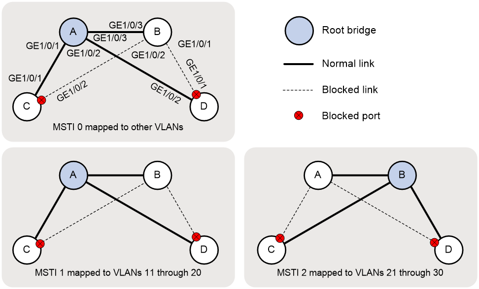
Based on the output, the topology for each MSTI is shown in Figure 3.
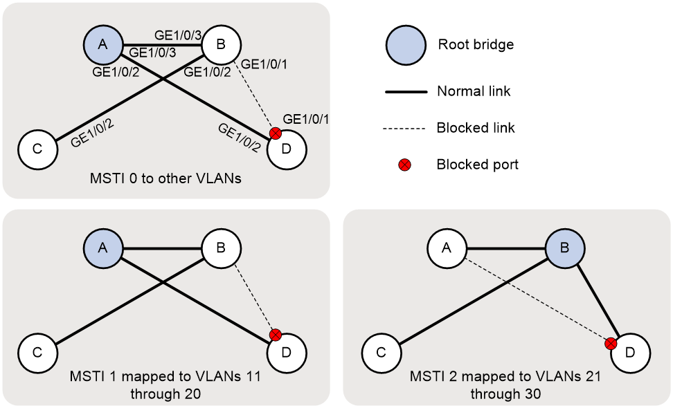
2. Verify that the network can accommodate topology changes:
# Shut down GigabitEthernet 1/0/1 on Device C.
[DeviceC] interface gigabitethernet 1/0/1
[DeviceC-GigabitEthernet1/0/1] shutdown
# Display brief spanning tree information on all devices.
[DeviceA] display stp brief
MST ID Port Role STP State Protection
0 GigabitEthernet1/0/2 DESI FORWARDING NONE
0 GigabitEthernet1/0/3 DESI FORWARDING NONE
1 GigabitEthernet1/0/2 DESI FORWARDING NONE
1 GigabitEthernet1/0/3 DESI FORWARDING NONE
2 GigabitEthernet1/0/2 DESI FORWARDING NONE
2 GigabitEthernet1/0/3 ROOT FORWARDING NONE
[DeviceB] display stp brief
MST ID Port Role STP State Protection
0 GigabitEthernet1/0/1 DESI FORWARDING NONE
0 GigabitEthernet1/0/2 DESI FORWARDING NONE
0 GigabitEthernet1/0/3 ROOT FORWARDING NONE
1 GigabitEthernet1/0/1 DESI FORWARDING NONE
1 GigabitEthernet1/0/2 DESI FORWARDING NONE
1 GigabitEthernet1/0/3 ROOT FORWARDING NONE
2 GigabitEthernet1/0/1 DESI FORWARDING NONE
2 GigabitEthernet1/0/2 DESI FORWARDING NONE
2 GigabitEthernet1/0/3 DESI FORWARDING NONE
[DeviceC] display stp brief
MST ID Port Role STP State Protection
0 GigabitEthernet1/0/2 ROOT FORWARDING NONE
1 GigabitEthernet1/0/2 ROOT FORWARDING NONE
2 GigabitEthernet1/0/2 ROOT FORWARDING NONE
[DeviceD] display stp brief
MST ID Port Role STP State Protection
0 GigabitEthernet1/0/1 ALTE DISCARDING NONE
0 GigabitEthernet1/0/2 ROOT FORWARDING NONE
1 GigabitEthernet1/0/1 ALTE DISCARDING NONE
1 GigabitEthernet1/0/2 ROOT FORWARDING NONE
2 GigabitEthernet1/0/1 ROOT FORWARDING NONE
2 GigabitEthernet1/0/2 ALTE DISCARDING NONE
Based on the output, the topology for each MSTI is shown in Figure 4.
Configuration files
· Device A:
#
vlan 1
#
vlan 11 to 30
#
stp region-configuration
region-name test
instance 1 vlan 11 to 20
instance 2 vlan 21 to 30
active region-configuration
#
stp instance 0 to 1 root primary
stp global enable
#
interface GigabitEthernet1/0/1
port link-mode bridge
port link-type trunk
port trunk permit vlan 1 11 to 30
#
interface GigabitEthernet1/0/2
port link-mode bridge
port link-type trunk
port trunk permit vlan 1 11 to 30
#
interface GigabitEthernet1/0/3
port link-mode bridge
port link-type trunk
port trunk permit vlan 1 11 to 30
· Device B:
#
vlan 1
#
vlan 11 to 30
#
stp region-configuration
region-name test
instance 1 vlan 11 to 20
instance 2 vlan 21 to 30
active region-configuration
#
stp instance 0 root secondary
stp instance 2 root primary
stp global enable
#
interface GigabitEthernet1/0/1
port link-mode bridge
port link-type trunk
port trunk permit vlan 1 11 to 30
#
interface GigabitEthernet1/0/2
port link-mode bridge
port link-type trunk
port trunk permit vlan 1 11 to 30
#
interface GigabitEthernet1/0/3
port link-mode bridge
port link-type trunk
port trunk permit vlan 1 11 to 30
· Device C:
#
vlan 1
#
vlan 11 to 30
#
stp region-configuration
region-name test
instance 1 vlan 11 to 20
instance 2 vlan 21 to 30
active region-configuration
#
stp global enable
#
interface GigabitEthernet1/0/1
port link-mode bridge
port link-type trunk
port trunk permit vlan 1 11 to 30
#
interface GigabitEthernet1/0/2
port link-mode bridge
port link-type trunk
port trunk permit vlan 1 11 to 30
· Device D:
#
vlan 1
#
vlan 11 to 30
#
stp region-configuration
region-name test
instance 1 vlan 11 to 20
instance 2 vlan 21 to 30
active region-configuration
#
stp instance 0 priority 36864
stp global enable
#
interface GigabitEthernet1/0/1
port link-mode bridge
port link-type trunk
port trunk permit vlan 1 11 to 30
#
interface GigabitEthernet1/0/2
port link-mode bridge
port link-type trunk
port trunk permit vlan 1 11 to 30
Related documentation
· Spanning tree configuration in the Layer 2—LAN switching configuration guide for the device.
· Spanning tree commands in the Layer 2—LAN switching command reference for the device.