- Table of Contents
-
- H3C Campus Fixed-Port Switches CLI-Based Quick Start Configuration Guide-6W101
- 01-H3C Devices CLI Reference
- 02-Login Management Quick Start Configuration Guide
- 03-Configuration File Management Quick Start Configruation Guide
- 04-Software Upgrade Quick Start Configuration Guide
- 05-Device Management Quick Start Configuration Guide
- 06-NTP Quick Start Configuration Guide
- 07-RBAC Quick Start Configuration Guide
- 08-IRF Quick Start Configuration Guide
- 09-Ethernet Interface Quick Start Configuration Guide
- 10-VLAN Quick Start Configuration Guide
- 11-Port Isolation Quick Start Configuration Guide
- 12-Loop Detection Quick Start Configuration Guide
- 13-QinQ Quick Start Configuration Guide
- 14-MAC Address Table Quick Start Configuration Guide
- 15-Ethernet Link Aggregation Quick Start Configuration Guide
- 16-Spanning Tree Quick Start Configuration Guide
- 17-DHCP Quick Start Configuration Guide
- 18-OSPF Quick Start Configuration Guide
- 19-Static Routing Quick Start Configuration Guide
- 20-Basic RIP Quick Start Configuration Guide
- 21-PBR Quick Start Configuration Guide
- 22-IGMP Snooping Quick Start Configuration Guide
- 23-Packet Filtering Quick Start Configuration Guide
- 24-QoS Quick Start Configuration Guide
- 25-IP Source Guard Quick Start Configuration Guide
- 26-SSH Quick Start Configuration Guide
- 27-Port Security Quick Start Configuration Guide
- 28-VRRP Quick Start Configuration Guide
- 29-PoE Quick Start Configuration Guide
- 30-Mirroring Quick Start Configuration Guide
- 31-Information Center Quick Start Configuration Guide
- 32-SNMP Quick Start Configuration Guide
- 33-LAN Networks Quick Start Configuration Guide
- Related Documents
-
| Title | Size | Download |
|---|---|---|
| 28-VRRP Quick Start Configuration Guide | 87.06 KB |
VRRP Quick Start Configuration Guide
Copyright © 2022 New H3C Technologies Co., Ltd. All rights reserved.
No part of this manual may be reproduced or transmitted in any form or by any means without prior written consent of New H3C Technologies Co., Ltd.
Except for the trademarks of New H3C Technologies Co., Ltd., any trademarks that may be mentioned in this document are the property of their respective owners.
The information in this document is subject to change without notice.
Configuring a single VRRP group
Introduction
The following information uses an example to describe the basic procedure for configuring a single VRRP group.
Network configuration
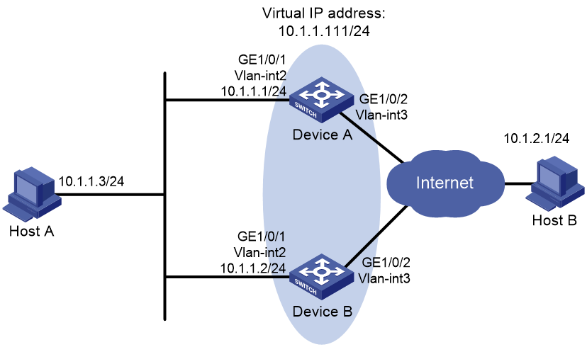
As shown in Figure 1, Host A needs to access Host B on the Internet. Two devices are deployed at the network egress of Host A. Configure a VRRP group on Device A and Device B to act as the default gateway for Host A and implement the following requirements:
· Device A operates as the master to forward packets from Host A to Host B.
· When Device A fails, Device B takes over to forward packets for Host A.
· When Device A recovers, Device A acts as the gateway again.
Restrictions and guidelines
· You cannot specify the virtual IP address as any of the following IP addresses:
¡ All-zero address (0.0.0.0).
¡ Broadcast address (255.255.255.255).
¡ Loopback address.
¡ IP address of other than Class A, Class B, and Class C.
¡ Invalid IP address (for example, 0.0.0.1).
· You can specify the IPv4 VRRP version as VRRPv2 or VRRPv3 (default version). The version of VRRP on all routers in an IPv4 VRRP group must be the same.
· The virtual IP address of an IPv4 VRRP group and the downlink interface IP addresses of the VRRP group members must be in the same subnet. Otherwise, the hosts in the subnet might fail to access external networks.
· Make sure all members in a VRRP group have the same virtual IP address configured.
· Make sure the reduced priority is lower than the priority of any other devices in the VRRP group, so that another device can be elected as master.
Procedure
Configure Device A
# Configure VLAN 2 and add GigabitEthernet 1/0/1 to VLAN 2.
<DeviceA> system-view
[DeviceA] vlan 2
[DeviceA-vlan2] port gigabitethernet 1/0/1
[DeviceA-vlan2] quit
# Create VLAN-interface 2 and set its IP address to 10.1.1.1/24.
[DeviceA] interface vlan-interface 2
[DeviceA-Vlan-interface2] ip address 10.1.1.1 255.255.255.0
# Create VRRP group 1 on VLAN-interface 2 and set its virtual IP address to 10.1.1.111.
[DeviceA-Vlan-interface2] vrrp vrid 1 virtual-ip 10.1.1.111
# Assign Device A a higher priority than Device B in VRRP group 1, so Device A can become the master.
[DeviceA-Vlan-interface2] vrrp vrid 1 priority 110
# Configure Device A to operate in preemptive mode, so it can become the master whenever it operates correctly. Set the preemption delay to 5000 centiseconds to avoid frequent status switchover.
[DeviceA-Vlan-interface2] vrrp vrid 1 preempt-mode delay 5000
[DeviceA-Vlan-interface2] quit
# Create track entry 1 associated with GigabitEthernet 1/0/2.
[DeviceA] track 1 interface gigabitethernet 1/0/2
[DeviceA-track-1] quit
# Create track entry 1. When the track entry transits to Negative state, Device A decreases its priority by 50 in the VRRP group.
[DeviceA] interface vlan-interface 2
[DeviceA-Vlan-interface2] vrrp vrid 1 track 1 priority reduced 50
[DeviceA-Vlan-interface2] quit
Configure Device B
# Configure VLAN 2.
<DeviceB> system-view
[DeviceB] vlan 2
[DeviceB-Vlan2] port gigabitethernet 1/0/1
[DeviceB-vlan2] quit
[DeviceB] interface vlan-interface 2
[DeviceB-Vlan-interface2] ip address 10.1.1.2 255.255.255.0
# Create VRRP group 1 on VLAN-interface 2 and set its virtual IP address to 10.1.1.111.
[DeviceB-Vlan-interface2] vrrp vrid 1 virtual-ip 10.1.1.111
# Set the priority of Device B to 100 in VRRP group 1.
[DeviceB-Vlan-interface2] vrrp vrid 1 priority 100
Verifying the configuration
# Ping Host B from Host A. (Details not shown.)
# Display detailed information about VRRP group 1 on Device A.
[DeviceA-Vlan-interface2] display vrrp verbose
IPv4 Virtual Router Information:
Running mode : Standard
Total number of virtual routers : 1
Interface Vlan-interface2
VRID : 1 Adver Timer : 100
Admin Status : Up State : Master
Config Pri : 110 Running Pri : 110
Preempt Mode : Yes Delay Time : 5000
Auth Type : Not supported
Version : 3
Virtual IP : 10.1.1.111
Virtual MAC : 0000-5e00-0101
Master IP : 10.1.1.1
VRRP Track Information:
Track Object : 1 State : Positive Pri Reduced : 50
# Display detailed information about VRRP group 1 on Device B.
[DeviceB-Vlan-interface2] display vrrp verbose
IPv4 Virtual Router Information:
Running mode : Standard
Total number of virtual routers : 1
Interface Vlan-interface2
VRID : 1 Adver Timer : 100
Admin Status : Up State : Backup
Config Pri : 100 Running Pri : 100
Preempt Mode : Yes Delay Time : 0
Become Master : 401ms left
Auth Type : Not supported
Version : 3
Virtual IP : 10.1.1.111
Master IP : 10.1.1.1
The output shows that Device A is operating as the master in VRRP group 1 to forward packets from Host A to Host B.
# When Device A fails, verify that Host A can still ping Host B. (Details not shown.)
# Display detailed information about VRRP group 1 on Device B.
[DeviceB-Vlan-interface2] display vrrp verbose
IPv4 Virtual Router Information:
Running Mode : Standard
Total number of virtual routers : 1
Interface Vlan-interface2
VRID : 1 Adver Timer : 100
Admin Status : Up State : Master
Config Pri : 100 Running Pri : 100
Preempt Mode : Yes Delay Time : 0
Auth Type : Not supported
Version : 3
Virtual IP : 10.1.1.111
Master IP : 10.1.1.2
The output shows that when Device A fails, Device B takes over to forward packets from Host A to Host B.
# After Device A recovers, display detailed information about VRRP group 1 on Device A.
[DeviceA-Vlan-interface2] display vrrp verbose
IPv4 Virtual Router Information:
Running Mode : Standard
Total number of virtual routers : 1
Interface Vlan-interface2
VRID : 1 Adver Timer : 100
Admin Status : Up State : Master
Config Pri : 110 Running Pri : 110
Preempt Mode : Yes Delay Time : 5000
Auth Type : Not supported
Version : 3
Virtual IP : 10.1.1.111
Virtual MAC : 0000-5e00-0101
Master IP : 10.1.1.1
VRRP Track Information:
Track Object : 1 State : Positive Pri Reduced : 50
The output shows that after Device A resumes normal operation, it becomes the master to forward packets from Host A to Host B.
Configuration files
· Device A:
#
vlan 2
#
interface Vlan-interface2
ip address 10.1.1.1 255.255.255.0
vrrp vrid 1 virtual-ip 10.1.1.111
vrrp vrid 1 priority 110
vrrp vrid 1 preempt-mode delay 5000
vrrp vrid 1 track 1 priority reduced 50
#
interface GigabitEthernet1/0/1
port link-mode bridge
port access vlan 2
#
track 1 interface Ten-GigabitEthernet1/0/2
#
· Device B:
#
vlan 2
#
interface Vlan-interface2
ip address 10.1.1.2 255.255.255.0
vrrp vrid 1 virtual-ip 10.1.1.111
vrrp vrid 1 priority 100
#
interface Ten-GigabitEthernet1/0/1
port link-mode bridge
port access vlan 2
#
Related documentation
· VRRP configuration in the high availability configuration guide for the device.
· VRRP commands in the high availability command reference for the device.