- Table of Contents
-
- H3C Campus Fixed-Port Switches CLI-Based Quick Start Configuration Guide-6W101
- 01-H3C Devices CLI Reference
- 02-Login Management Quick Start Configuration Guide
- 03-Configuration File Management Quick Start Configruation Guide
- 04-Software Upgrade Quick Start Configuration Guide
- 05-Device Management Quick Start Configuration Guide
- 06-NTP Quick Start Configuration Guide
- 07-RBAC Quick Start Configuration Guide
- 08-IRF Quick Start Configuration Guide
- 09-Ethernet Interface Quick Start Configuration Guide
- 10-VLAN Quick Start Configuration Guide
- 11-Port Isolation Quick Start Configuration Guide
- 12-Loop Detection Quick Start Configuration Guide
- 13-QinQ Quick Start Configuration Guide
- 14-MAC Address Table Quick Start Configuration Guide
- 15-Ethernet Link Aggregation Quick Start Configuration Guide
- 16-Spanning Tree Quick Start Configuration Guide
- 17-DHCP Quick Start Configuration Guide
- 18-OSPF Quick Start Configuration Guide
- 19-Static Routing Quick Start Configuration Guide
- 20-Basic RIP Quick Start Configuration Guide
- 21-PBR Quick Start Configuration Guide
- 22-IGMP Snooping Quick Start Configuration Guide
- 23-Packet Filtering Quick Start Configuration Guide
- 24-QoS Quick Start Configuration Guide
- 25-IP Source Guard Quick Start Configuration Guide
- 26-SSH Quick Start Configuration Guide
- 27-Port Security Quick Start Configuration Guide
- 28-VRRP Quick Start Configuration Guide
- 29-PoE Quick Start Configuration Guide
- 30-Mirroring Quick Start Configuration Guide
- 31-Information Center Quick Start Configuration Guide
- 32-SNMP Quick Start Configuration Guide
- 33-LAN Networks Quick Start Configuration Guide
- Related Documents
-
| Title | Size | Download |
|---|---|---|
| 08-IRF Quick Start Configuration Guide | 120.40 KB |
IRF Quick Start Configuration Guide
Copyright © 2022 New H3C Technologies Co., Ltd. All rights reserved.
No part of this manual may be reproduced or transmitted in any form or by any means without prior written consent of New H3C Technologies Co., Ltd.
Except for the trademarks of New H3C Technologies Co., Ltd., any trademarks that may be mentioned in this document are the property of their respective owners.
The information in this document is subject to change without notice.
Setting up a two-member IRF fabric
Introduction
The Intelligent Resilient Framework (IRF) technology enables you to add device nodes for forwarding capacity expansion without changing network topology. The following information uses an example to describe the basic procedure for two-member IRF fabric setup.
Network configuration
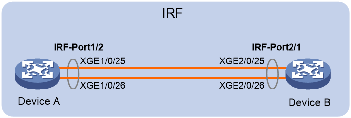
As shown in Figure 1, add Device B to expand Device A at the core layer of a network into a two-member IRF fabric to accommodate growing traffic without changing the network topology.
Analysis and data preparation
The following is the summary procedure for IRF setup:
1. Assign a unique IRF member ID to each device.
If you change the IRF member ID of a device, you must reboot the device for the new member ID to take effect.
2. Assign an IRF member priority to each device for master election.
Assign a higher priority to the device to be used as the master.
3. Bind physical interfaces to IRF ports.
4. Save the configuration.
5. Connect the peer IRF physical interfaces between the IRF member devices.
6. Activate the IRF port settings on each device.
This example uses the configuration data in Table 1 for IRF setup.
|
Device |
IRF member ID |
IRF member priority |
IRF port bindings |
|
Device A |
1 (default) |
32 |
IRF port: irf-port 1/2 IRF physical interfaces: · Ten-GigabitEthernet 1/0/25 · Ten-GigabitEthernet 1/0/26 |
|
Device B |
2 |
1 (default) |
IRF port: irf-port 2/1 IRF physical interfaces: · Ten-GigabitEthernet 2/0/25 · Ten-GigabitEthernet 2/0/26 |
Restrictions and guidelines
IRF ports are numbered in member-id/port-id format, with port-id being 1 or 2. To set up an IRF fabric, make sure the peer IRF ports connected between neighboring member devices have different port IDs. If you use IRF-port member-id/1 on one member device, you must connect it to IRF-port member-id/2 on the other.
For example, Device A has a member ID of 1 and Device B has a member ID of 2. You can use either of the following IRF port connection schemes:
· IRF-port 1/2 (Device A) to IRF-port 2/1 (Device B). This example uses this connection scheme.
· IRF-port 1/1 (Device A) to IRF-port 2/2 (Device B).
Procedures
Configuring Device A
# Assign a member ID to Device A. In this example, this step is skipped for Device A, because it uses the default member ID (1).
# Bind Ten-GigabitEthernet 1/0/25 and Ten-GigabitEthernet 1/0/26 to IRF-port 1/2.
<DeviceA> system-view
[DeviceA] interface ten-gigabitethernet 1/0/25
[DeviceA-Ten-GigabitEthernet1/0/25] shutdown
[DeviceA-Ten-GigabitEthernet1/0/25] quit
[DeviceA] interface ten-gigabitethernet 1/0/26
[DeviceA-Ten-GigabitEthernet1/0/26] shutdown
[DeviceA-Ten-GigabitEthernet1/0/26] quit
[DeviceA] irf-port 1/2
[DeviceA-irf-port1/2] port group interface ten-gigabitethernet1/0/25
[DeviceA-irf-port1/2] port group interface ten-gigabitethernet1/0/26
[DeviceA-irf-port1/2] quit
[DeviceA] interface ten-gigabitethernet 1/0/25
[DeviceA-Ten-GigabitEthernet1/0/25] undo shutdown
[DeviceA-Ten-GigabitEthernet1/0/25] quit
[DeviceA] interface ten-gigabitethernet 1/0/26
[DeviceA-Ten-GigabitEthernet1/0/26] undo shutdown
[DeviceA-Ten-GigabitEthernet1/0/26] quit
# Assign IRF member priority 32 to Device A. This priority is high enough to ensure that Device A can be elected as the master.
[DeviceA] irf member 1 priority 32
# Save the configuration.
[DeviceA] save force
Configuring Device B
# Assign member ID 2 to Device B, and then reboot the device to have the new member ID take effect.
<DeviceB> system-view
[DeviceB] irf member 1 renumber 2
Warning: Renumbering the switch number may result in configuration change or loss. Continue? [Y/N]:y
[DeviceB] quit
<DeviceB> reboot
# Bind Ten-GigabitEthernet 2/0/25 and Ten-GigabitEthernet 2/0/26 to IRF-port 2/1.
[DeviceB] interface ten-gigabitethernet 2/0/25
[DeviceB-Ten-GigabitEthernet2/0/25] shutdown
[DeviceB-Ten-GigabitEthernet2/0/25] quit
[DeviceB] interface ten-gigabitethernet 2/0/26
[DeviceB-Ten-GigabitEthernet2/0/26] shutdown
[DeviceB-Ten-GigabitEthernet2/0/26] quit
[DeviceB] irf-port 2/1
[DeviceB-irf-port2/1] port group interface ten-gigabitethernet2/0/25
[DeviceB-irf-port2/1] port group interface ten-gigabitethernet2/0/26
[DeviceB-irf-port2/1] quit
[DeviceB] interface ten-gigabitethernet 2/0/25
[DeviceB-Ten-GigabitEthernet2/0/25] undo shutdown
[DeviceB-Ten-GigabitEthernet2/0/25] quit
[DeviceB] interface ten-gigabitethernet 2/0/26
[DeviceB-Ten-GigabitEthernet2/0/26] undo shutdown
[DeviceB-Ten-GigabitEthernet2/0/26] quit
# Save the configuration.
[DeviceB] save force
# Connect the IRF physical interfaces on Device B to their peer IRF physical interfaces on Device A, as shown in Figure 1.
Activating the IRF port settings
# Activate the IRF port settings on Device A.
[DeviceA] irf-port-configuration active
# Activate the IRF port settings on Device B.
[DeviceB] irf-port-configuration active
Device B and Device perform master election automatically. With a lower priority than Device A, Device B fails master election and reboots to form an IRF fabric with Device A. The system name of the IRF fabric is Device A.
Verifying the configuration
# Verify that the IRF fabric has been established.
<DeviceA> display irf
MemberID Slot Role Priority CPU-Mac Description
*+1 0 Master 32 0210-fc01-0000 ---
2 0 Standby 1 0210-fc02-0000 ---
--------------------------------------------------
* indicates the device is the master.
+ indicates the device through which the user logs in.
The Bridge MAC of the IRF is: 3822-d60f-2800
Auto upgrade : yes
Mac persistent : always
Domain ID : 0
Auto merge : yes
The output shows that the IRF fabric has been established.
Configuration files
· Device A:
#
irf member 1 renumber 2
#
irf-port 1/2
port group interface ten-gigabitethernet1/0/25
port group interface ten-gigabitethernet1/0/26
#
irf-port-configuration active
#
· Device B:
#
irf-port 2/1
port group interface ten-gigabitethernet2/0/25
port group interface ten-gigabitethernet2/0/26
#
irf-port-configuration active
#
Related documentation
· IRF configuration in the virtual technologies configuration guide for the device.
· IRF commands in the virtual technologies command reference for the device.
Configuring BFD MAD for IRF split detection
Introduction
IRF link failure might cause an IRF fabric to split in two IRF fabrics operating with the same Layer 3 settings, including the same IP address. To avoid IP address collision and other network issues caused by an IRF split, IRF provides multi-active detection (MAD) mechanisms to detect the presence of multiple conflicting active IRF fabrics, handle collisions, and recover from faults. One of the most commonly used MAD mechanisms extends the Bidirectional Forwarding Detection (BFD) protocol to detect multi-active conflicts.
When a two-member IRF fabric splits, BFD MAD places the device with the higher member ID in Recovery state and shuts down all common network interfaces on it except for the interfaces automatically or manually excluded from being shut down by any MAD mechanisms. In this situation, only the device with the lower member ID can continue to forward traffic.
The following information uses an example to describe the basis BFD MAD configuration procedure.
Network configuration
Figure 2 shows an IRF fabric that contains Device A and Device B. Configure BFD MAD on the IRF fabric to detect multi-active conflicts.

Restrictions and guidelines
· Disable the spanning tree feature on all Layer 2 Ethernet ports in the BFD MAD VLAN. BFD MAD is mutually exclusive with the spanning tree feature.
· Do not configure the BFD MAD VLAN interface and its member ports for any purpose other than BFD MAD. If you configure them to provide other services, both BFD MAD and other services might operate incorrectly.
Procedures
Setting up the IRF fabric
Configure Device A and Device B to establish an IRF fabric. For more information about the procedure see "Setting up a two-member IRF fabric."
Configuring BFD MAD on the IRF fabric
# Create VLAN 3 (BFD MAD VLAN) and add port GigabitEthernet 1/0/1 on Device A and port GigabitEthernet 2/0/1 on Device B to the VLAN.
<IRF> system-view
[IRF] vlan 3
[IRF-vlan3] port gigabitethernet 1/0/1 gigabitethernet 2/0/1
[IRF-vlan3] quit
# Create VLAN-interface 3 and assign a MAD IP address to each member device on the interface.
[IRF] interface vlan-interface 3
[IRF-Vlan-interface3] mad bfd enable
[IRF-Vlan-interface3] mad ip address 192.168.2.1 24 member 1
[IRF-Vlan-interface3] mad ip address 192.168.2.2 24 member 2
[IRF-Vlan-interface3] quit
# Disable the spanning tree feature on the ports in the BFD MAD VLAN.
[IRF] interface gigabitethernet 1/0/1
[IRF-gigabitethernet1/0/1] undo stp enable
[IRF-gigabitethernet1/0/1] quit
[IRF] interface gigabitethernet 2/0/1
[IRF-gigabitethernet2/0/1] undo stp enable
Verifying the configuration
After the IRF fabric splits, verify that BFD MAD operates correctly:
# Execute the display mad verbose command on Device A. Verify that the Multi-active recovery state field in the command output is No and Device A can continue to forward traffic.
<DeviceA> display mad
MAD ARP disabled.
MAD ND disabled.
MAD LACP disabled.
MAD BFD enabled.
<DeviceA> display mad verbose
Multi-active recovery state: No
Excluded ports (user-configured):
Excluded ports (system-configured):
Ten-GigabitEthernet1/1/1
MAD ARP disabled.
MAD ND disabled.
MAD LACP disabled.
MAD BFD enabled interface: Vlan-interface3
MAD status : Faulty
Member ID MAD IP address Neighbor MAD status
1 192.168.2.1/24 2 Faulty
# On Device B, execute the display interface brief down command. Verify that all network ports on it have been shut down by MAD except those automatically or manually excluded from the MAD shutdown action.
<DeviceB> display interface brief down
Brief information on interfaces in route mode:
Link: ADM - administratively down; Stby - standby
Interface Link Cause
GE2/0/2 DOWN MAD ShutDown
GE2/0/3 DOWN MAD ShutDown
Configuration files
#
vlan 3
port gigabitethernet 1/0/1 gigabitethernet 2/0/1
#
interface vlan-interface 3
mad bfd enable
mad ip address 192.168.2.1 24 member 1
mad ip address 192.168.2.2 24 member 2
#
interface gigabitethernet 1/0/1
undo stp enable
#
interface gigabitethernet 2/0/1
undo stp enable
#
Related documentation
· IRF configuration in the virtual technologies configuration guide for the device.
· IRF commands in the virtual technologies command reference for the device.