- Table of Contents
-
- H3C Campus Fixed-Port Switches CLI-Based Quick Start Configuration Guide-6W101
- 01-H3C Devices CLI Reference
- 02-Login Management Quick Start Configuration Guide
- 03-Configuration File Management Quick Start Configruation Guide
- 04-Software Upgrade Quick Start Configuration Guide
- 05-Device Management Quick Start Configuration Guide
- 06-NTP Quick Start Configuration Guide
- 07-RBAC Quick Start Configuration Guide
- 08-IRF Quick Start Configuration Guide
- 09-Ethernet Interface Quick Start Configuration Guide
- 10-VLAN Quick Start Configuration Guide
- 11-Port Isolation Quick Start Configuration Guide
- 12-Loop Detection Quick Start Configuration Guide
- 13-QinQ Quick Start Configuration Guide
- 14-MAC Address Table Quick Start Configuration Guide
- 15-Ethernet Link Aggregation Quick Start Configuration Guide
- 16-Spanning Tree Quick Start Configuration Guide
- 17-DHCP Quick Start Configuration Guide
- 18-OSPF Quick Start Configuration Guide
- 19-Static Routing Quick Start Configuration Guide
- 20-Basic RIP Quick Start Configuration Guide
- 21-PBR Quick Start Configuration Guide
- 22-IGMP Snooping Quick Start Configuration Guide
- 23-Packet Filtering Quick Start Configuration Guide
- 24-QoS Quick Start Configuration Guide
- 25-IP Source Guard Quick Start Configuration Guide
- 26-SSH Quick Start Configuration Guide
- 27-Port Security Quick Start Configuration Guide
- 28-VRRP Quick Start Configuration Guide
- 29-PoE Quick Start Configuration Guide
- 30-Mirroring Quick Start Configuration Guide
- 31-Information Center Quick Start Configuration Guide
- 32-SNMP Quick Start Configuration Guide
- 33-LAN Networks Quick Start Configuration Guide
- Related Documents
-
| Title | Size | Download |
|---|---|---|
| 11-Port Isolation Quick Start Configuration Guide | 72.14 KB |
Port Isolation Quick Start Configuration Guide
Copyright © 2022 New H3C Technologies Co., Ltd. All rights reserved.
No part of this manual may be reproduced or transmitted in any form or by any means without prior written consent of New H3C Technologies Co., Ltd.
Except for the trademarks of New H3C Technologies Co., Ltd., any trademarks that may be mentioned in this document are the property of their respective owners.
The information in this document is subject to change without notice.
Contents
Configuring port isolation
Introduction
The following information uses an example to describe the basic port isolation configuration procedure.
Network configuration
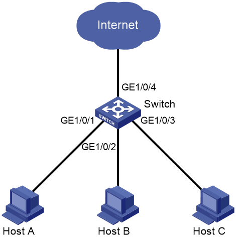
As shown in Figure 1, the community users Host A, Host B, and Host C are connected to GigabitEthernet 1/0/1, GigabitEthernet 1/0/2, and GigabitEthernet 1/0/3 of Switch, respectively. Switch is connected to Internet through GigabitEthernet 1/0/4.
Configure port isolation to isolate Layer 2 packets among Host A, Host B, and Host C, and allow these hosts to communicate with Internet.
Restrictions and guidelines
· To assign a port on a device to an isolation group, first create the isolation group.
· A port can be assigned to only one isolation group.
Procedure
|
|
IMPORTANT: On a device that supports only one isolation group, the system automatically creates isolation group 1. You cannot delete the isolation group or create any other isolation group. On a device that supports multiple isolation groups, you can manually configure isolation groups. |
# Create isolation group 1.
<Switch> system-view
[Switch] port-isolate group 1
# Assign ports GigabitEthernet 1/0/1, GigabitEthernet 1/0/2, and GigabitEthernet 1/0/3 to isolation group 1.
[Switch] interface gigabitethernet 1/0/1
[Switch-GigabitEthernet1/0/1] port-isolate enable group 1
[Switch-GigabitEthernet1/0/1] quit
[Switch] interface gigabitethernet 1/0/2
[Switch-GigabitEthernet1/0/2] port-isolate enable group 1
[Switch-GigabitEthernet1/0/2] quit
[Switch] interface gigabitethernet 1/0/3
[Switch-GigabitEthernet1/0/3] port-isolate enable group 1
[Switch-GigabitEthernet1/0/3] quit
# Save the configuration.
[Switch] save force
Verifying the configuration
# Display information about isolation group 1.
[Switch] display port-isolate group 1
Port isolation group information:
Group ID: 1
Group members:
GigabitEthernet1/0/1
GigabitEthernet1/0/2
GigabitEthernet1/0/3
The command output shows that GigabitEthernet 1/0/1, GigabitEthernet 1/0/2, and GigabitEthernet 1/0/3 on Switch have been assigned to isolation group 1 and isolated from each other at Layer 2. Host A, Host B, and Host C cannot ping each other.
Configuration files
#
port-isolate group 1
#
interface GigabitEthernet1/0/1
port link-mode bridge
port-isolate enable group 1
#
interface GigabitEthernet1/0/2
port link-mode bridge
port-isolate enable group 1
#
interface GigabitEthernet1/0/3
port link-mode bridge
port-isolate enable group 1
#
Related documentation
· Port isolation configuration in the Layer 2—Ethernet switching configuration guide for the device.
· Port isolation commands in the Layer 2—Ethernet switching command reference for the device.
