- Table of Contents
-
- H3C Campus Fixed-Port Switches CLI-Based Quick Start Configuration Guide-6W101
- 01-H3C Devices CLI Reference
- 02-Login Management Quick Start Configuration Guide
- 03-Configuration File Management Quick Start Configruation Guide
- 04-Software Upgrade Quick Start Configuration Guide
- 05-Device Management Quick Start Configuration Guide
- 06-NTP Quick Start Configuration Guide
- 07-RBAC Quick Start Configuration Guide
- 08-IRF Quick Start Configuration Guide
- 09-Ethernet Interface Quick Start Configuration Guide
- 10-VLAN Quick Start Configuration Guide
- 11-Port Isolation Quick Start Configuration Guide
- 12-Loop Detection Quick Start Configuration Guide
- 13-QinQ Quick Start Configuration Guide
- 14-MAC Address Table Quick Start Configuration Guide
- 15-Ethernet Link Aggregation Quick Start Configuration Guide
- 16-Spanning Tree Quick Start Configuration Guide
- 17-DHCP Quick Start Configuration Guide
- 18-OSPF Quick Start Configuration Guide
- 19-Static Routing Quick Start Configuration Guide
- 20-Basic RIP Quick Start Configuration Guide
- 21-PBR Quick Start Configuration Guide
- 22-IGMP Snooping Quick Start Configuration Guide
- 23-Packet Filtering Quick Start Configuration Guide
- 24-QoS Quick Start Configuration Guide
- 25-IP Source Guard Quick Start Configuration Guide
- 26-SSH Quick Start Configuration Guide
- 27-Port Security Quick Start Configuration Guide
- 28-VRRP Quick Start Configuration Guide
- 29-PoE Quick Start Configuration Guide
- 30-Mirroring Quick Start Configuration Guide
- 31-Information Center Quick Start Configuration Guide
- 32-SNMP Quick Start Configuration Guide
- 33-LAN Networks Quick Start Configuration Guide
- Related Documents
-
| Title | Size | Download |
|---|---|---|
| 20-Basic RIP Quick Start Configuration Guide | 65.33 KB |
Basic RIP Quick Start Configuration Guide
Copyright © 2022 New H3C Technologies Co., Ltd. All rights reserved.
No part of this manual may be reproduced or transmitted in any form or by any means without prior written consent of New H3C Technologies Co., Ltd.
Except for the trademarks of New H3C Technologies Co., Ltd., any trademarks that may be mentioned in this document are the property of their respective owners.
The information in this document is subject to change without notice.
Configuring basic RIP settings
Introduction
The following information uses an example to describe the basic procedure for configuring basic RIP settings.
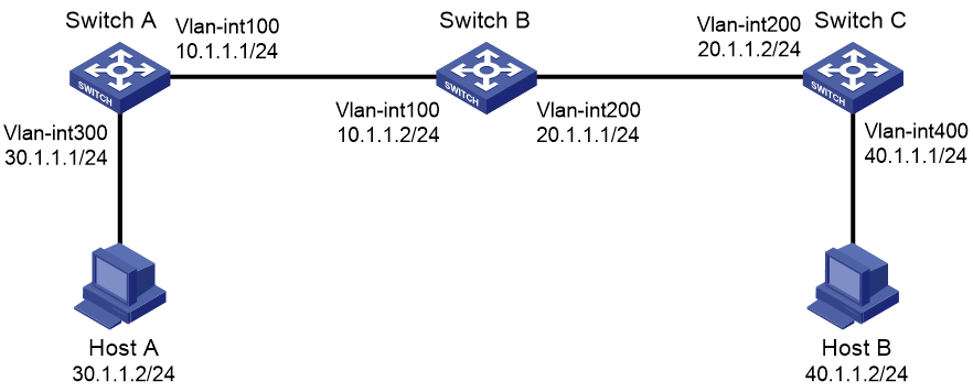
Network configuration
As shown in Figure 1, enable RIPv2 on all switches so that Host A and Host B can communicate with each other.
Procedure
Configuring Host A and Host B
# Configure IP address 30.1.1.2, subnet mask 255.255.255.0, and gateway address 30.1.1.1 for Host A. (Details not shown.)
# Configure IP address 40.1.1.2, subnet mask 255.255.255.0, and gateway address 40.1.1.1 for Host B. (Details not shown.)
Configuring Switch A
# Create VLANs and assign ports to them. Configure the IP address of each VLAN interface.
<SwitchA> system-view
[SwitchA] vlan 100
[SwitchA-vlan100] port gigabitethernet 1/0/1
[SwitchA-vlan100] quit
[SwitchA] vlan 300
[SwitchA-vlan300] port gigabitethernet 1/0/2
[SwitchA-vlan300] quit
[SwitchA] interface vlan-interface 100
[SwitchA-Vlan-interface100] ip address 10.1.1.1 24
[SwitchA-Vlan-interface100] quit
[SwitchA] interface vlan-interface 300
[SwitchA-Vlan-interface300] ip address 30.1.1.1 24
[SwitchA-Vlan-interface300] quit
# Configure RIPv2 settings.
[SwitchA] rip
[SwitchA-rip-1] network 10.1.1.0
[SwitchA-rip-1] network 30.1.1.0
[SwitchA-rip-1] version 2
[SwitchA-rip-1] undo summary
[SwitchA-rip-1] quit
# Save the configuration.
[SwitchA] save force
Configuring Switch B
# Create VLANs and assign ports to them. Configure the IP address of each VLAN interface.
<SwitchB> system-view
[SwitchB] vlan 100
[SwitchB-vlan100] port gigabitethernet 1/0/1
[SwitchB-vlan100] quit
[SwitchB] vlan 200
[SwitchB-vlan200] port gigabitethernet 1/0/2
[SwitchB-vlan200] quit
[SwitchB] interface vlan-interface 100
[SwitchB-Vlan-interface100] ip address 10.1.1.2 24
[SwitchB-Vlan-interface100] quit
[SwitchB] interface vlan-interface 200
[SwitchB-Vlan-interface200] ip address 20.1.1.1 24
[SwitchB-Vlan-interface200] quit
# Configure RIPv2 settings.
[SwitchB] rip
[SwitchB-rip-1] network 10.1.1.0
[SwitchB-rip-1] network 20.1.1.0
[SwitchB-rip-1] version 2
[SwitchB-rip-1] undo summary
[SwitchB-rip-1] quit
# Save the configuration.
[SwitchB] save force
Configuring Switch C
# Create VLANs and assign ports to them. Configure the IP address of each VLAN interface.
<SwitchC> system-view
[SwitchC] vlan 200
[SwitchC-vlan200] port gigabitethernet 1/0/1
[SwitchC-vlan200] quit
[SwitchC] vlan 400
[SwitchC-vlan400] port gigabitethernet 1/0/2
[SwitchC-vlan400] quit
[SwitchC] interface vlan-interface 200
[SwitchC-Vlan-interface200] ip address 20.1.1.2 24
[SwitchC-Vlan-interface200] quit
[SwitchC] interface vlan-interface 400
[SwitchC-Vlan-interface400] ip address 40.1.1.1 24
[SwitchC-Vlan-interface400] quit
# Configure RIPv2 settings.
[SwitchC] rip
[SwitchC-rip-1] network 20.1.1.0
[SwitchC-rip-1] network 40.1.1.0
[SwitchC-rip-1] version 2
[SwitchC-rip-1] undo summary
[SwitchC-rip-1] quit
# Save the configuration.
[SwitchC] save force
Verifying the configuration
# Display the RIP routing table of Switch A.
[SwitchA] display rip 1 route
Route Flags: R - RIP, T - TRIP
P - Permanent, A - Aging, S - Suppressed, G - Garbage-collect
D - Direct, O - Optimal, F - Flush to RIB
----------------------------------------------------------------------------
Peer 10.1.1.2 on Vlan-interface100
Destination/Mask Nexthop Cost Tag Flags Sec
20.1.1.0/24 10.1.1.2 1 0 RAOF 27
40.1.1.0/24 10.1.1.2 2 0 RAOF 27
Local route
Destination/Mask Nexthop Cost Tag Flags Sec
10.1.1.0/24 0.0.0.0 0 0 RDOF -
30.1.1.0/24 0.0.0.0 0 0 RDOF -
# Display the RIP routing table of Switch B.
[SwitchB] display rip 1 route
Route Flags: R - RIP, T - TRIP
P - Permanent, A - Aging, S - Suppressed, G - Garbage-collect
D - Direct, O - Optimal, F - Flush to RIB
----------------------------------------------------------------------------
Peer 10.1.1.1 on Vlan-interface100
Destination/Mask Nexthop Cost Tag Flags Sec
30.1.1.0/24 10.1.1.1 1 0 RAOF 0
Peer 20.1.1.2 on Vlan-interface200
Destination/Mask Nexthop Cost Tag Flags Sec
40.1.1.0/24 20.1.1.2 1 0 RAOF 9
Local route
Destination/Mask Nexthop Cost Tag Flags Sec
20.1.1.0/24 0.0.0.0 0 0 RDOF -
10.1.1.0/24 0.0.0.0 0 0 RDOF -
# Display the RIP routing table of Switch C.
[SwitchC] display rip 1 route
Route Flags: R - RIP, T - TRIP
P - Permanent, A - Aging, S - Suppressed, G - Garbage-collect
D - Direct, O - Optimal, F - Flush to RIB
----------------------------------------------------------------------------
Peer 20.1.1.1 on Vlan-interface200
Destination/Mask Nexthop Cost Tag Flags Sec
10.1.1.0/24 20.1.1.1 1 0 RAOF 32
30.1.1.0/24 20.1.1.1 2 0 RAOF 32
Local route
Destination/Mask Nexthop Cost Tag Flags Sec
20.1.1.0/24 0.0.0.0 0 0 RDOF -
40.1.1.0/24 0.0.0.0 0 0 RDOF -
# Ping Host B on Host A to verify that Host B is reachable (assuming Windows XP is installed on the host).
C:\Documents and Settings\Administrator>ping 40.1.1.2
Pinging 40.1.1.2 with 32 bytes of data:
Reply from 40.1.1.2: bytes=32 time=1ms TTL=126
Reply from 40.1.1.2: bytes=32 time=1ms TTL=126
Reply from 40.1.1.2: bytes=32 time=1ms TTL=126
Reply from 40.1.1.2: bytes=32 time=1ms TTL=126
Ping statistics for 40.1.1.2:
Packets: Sent = 4, Received = 4, Lost = 0 (0% loss),
Approximate round trip times in milli-seconds:
Minimum = 1ms, Maximum = 1ms, Average = 1ms
Configuration files
· Switch A:
#
rip 1
undo summary
version 2
network 10.0.0.0
network 30.0.0.0
#
vlan 100
#
vlan 300
#
interface Vlan-interface100
ip address 10.1.1.1 255.255.255.0
#
interface Vlan-interface300
ip address 30.1.1.1 255.255.255.0
#
interface GigabitEthernet1/0/1
port link-mode bridge
port access vlan 100
#
interface GigabitEthernet1/0/2
port link-mode bridge
port access vlan 300
#
· Switch B:
#
rip 1
undo summary
version 2
network 10.0.0.0
network 20.0.0.0
#
vlan 100
#
vlan 200
#
interface Vlan-interface100
ip address 10.1.1.2 255.255.255.0
#
interface Vlan-interface200
ip address 20.1.1.1 255.255.255.0
#
interface GigabitEthernet1/0/1
port link-mode bridge
port access vlan 100
#
interface GigabitEthernet1/0/2
port link-mode bridge
port access vlan 200
#
· Switch C:
#
rip 1
undo summary
version 2
network 20.0.0.0
network 40.0.0.0
#
vlan 200
#
vlan 400
#
interface Vlan-interface200
ip address 20.1.1.2 255.255.255.0
#
interface Vlan-interface400
ip address 40.1.1.1 255.255.255.0
#
interface GigabitEthernet1/0/1
port link-mode bridge
port access vlan 200
#
interface GigabitEthernet1/0/2
port link-mode bridge
port access vlan 400
#
Related documentation
· RIP configuration in the Layer 3—IP routing configuration guide for the device.
· RIP commands in the Layer 3—IP routing command reference for the device.