- Table of Contents
-
- H3C Campus Fixed-Port Switches CLI-Based Quick Start Configuration Guide-6W101
- 01-H3C Devices CLI Reference
- 02-Login Management Quick Start Configuration Guide
- 03-Configuration File Management Quick Start Configruation Guide
- 04-Software Upgrade Quick Start Configuration Guide
- 05-Device Management Quick Start Configuration Guide
- 06-NTP Quick Start Configuration Guide
- 07-RBAC Quick Start Configuration Guide
- 08-IRF Quick Start Configuration Guide
- 09-Ethernet Interface Quick Start Configuration Guide
- 10-VLAN Quick Start Configuration Guide
- 11-Port Isolation Quick Start Configuration Guide
- 12-Loop Detection Quick Start Configuration Guide
- 13-QinQ Quick Start Configuration Guide
- 14-MAC Address Table Quick Start Configuration Guide
- 15-Ethernet Link Aggregation Quick Start Configuration Guide
- 16-Spanning Tree Quick Start Configuration Guide
- 17-DHCP Quick Start Configuration Guide
- 18-OSPF Quick Start Configuration Guide
- 19-Static Routing Quick Start Configuration Guide
- 20-Basic RIP Quick Start Configuration Guide
- 21-PBR Quick Start Configuration Guide
- 22-IGMP Snooping Quick Start Configuration Guide
- 23-Packet Filtering Quick Start Configuration Guide
- 24-QoS Quick Start Configuration Guide
- 25-IP Source Guard Quick Start Configuration Guide
- 26-SSH Quick Start Configuration Guide
- 27-Port Security Quick Start Configuration Guide
- 28-VRRP Quick Start Configuration Guide
- 29-PoE Quick Start Configuration Guide
- 30-Mirroring Quick Start Configuration Guide
- 31-Information Center Quick Start Configuration Guide
- 32-SNMP Quick Start Configuration Guide
- 33-LAN Networks Quick Start Configuration Guide
- Related Documents
-
| Title | Size | Download |
|---|---|---|
| 10-VLAN Quick Start Configuration Guide | 162.66 KB |
VLAN Quick Start Configuration Guide
Copyright © 2022 New H3C Technologies Co., Ltd. All rights reserved.
No part of this manual may be reproduced or transmitted in any form or by any means without prior written consent of New H3C Technologies Co., Ltd.
Except for the trademarks of New H3C Technologies Co., Ltd., any trademarks that may be mentioned in this document are the property of their respective owners.
The information in this document is subject to change without notice.
Contents
Configuring port-based VLANs
Introduction
The following information uses an example to describe the basic procedure for configuring port-based VLANs.
Network configuration
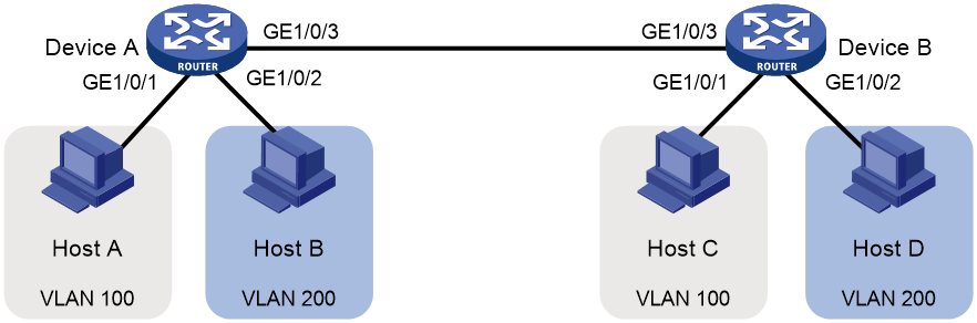
As shown in Figure 1, Host A and Host C belong to department A, but they access the company network through different devices. Host B and Host D belong to department B, but they access the company network through different devices. To ensure communication security and avoid flooding broadcast packets, you can use VLANs to isolate Layer 2 traffic of different departments. Configure department A to use VLAN 100, and configure department B to use VLAN 200. Then, hosts in the same VLAN can communicate. Host A and Host C can communicate. Host B and Host D can communicate.
Procedures
Configuring Device A
# Create VLAN 100. Assign GigabitEthernet 1/0/1 to VLAN 10.
<DeviceA> system-view
[DeviceA] vlan 100
[DeviceA-vlan100] port gigabitethernet 1/0/1
[DeviceA-vlan100] quit
# Create VLAN 200. Assign GigabitEthernet 1/0/2 to VLAN 200.
[DeviceA] vlan 100
[DeviceA-vlan200] port GigabitEthernet 1/0/2
[DeviceA-vlan200] quit
# To forward packets from VLANs 100 and 200 on Device A to Device B, set the link type of GigabitEthernet 1/0/2 to trunk, and assign it to VLANs 100 and 200.
[DeviceA] interface gigabitethernet 1/0/3
[DeviceA-GigabitEthernet1/0/3] port link-type trunk
[DeviceA-GigabitEthernet1/0/3] port trunk permit vlan 100 200
[DeviceA-GigabitEthernet1/0/3] quit
# Save the configuration.
[DeviceA] save force
Configuring Device B
# Create VLAN 100. Assign GigabitEthernet 1/0/1 to VLAN 100.
<DeviceB> system-view
[DeviceB] vlan 100
[DeviceB-vlan100] port gigabitethernet 1/0/1
[DeviceB-vlan100] quit
# Create VLAN 200. Assign GigabitEthernet 1/0/2 to VLAN 200.
[DeviceB] vlan 200
[DeviceB-vlan200] port gigabitethernet 1/0/2
[DeviceB-vlan200] quit
# To forward packets from VLANs 100 and 200 on Device B to Device A, set the link type of GigabitEthernet 1/0/3 to trunk, and assign it to VLANs 100 and 200.
[DeviceB] interface gigabitethernet 1/0/3
[DeviceB-GigabitEthernet1/0/3] port link-type trunk
[DeviceB-GigabitEthernet1/0/3] port trunk permit vlan 100 200
[DeviceB-GigabitEthernet1/0/3] quit
# Save the configuration.
[DeviceB] save force
# Assign Host A and Host C to the same subnet, for example, 192.168.100.0/24. Assign Host B and Host D to the same subnet, for example, 192.168.200.0/24.
Verifying the configuration
# Display information about VLANs on Device A.
<DeviceA> display vlan 100
VLAN ID: 100
VLAN type: Static
Route interface: Not configured
Description: VLAN 0100
Name: VLAN 0100
Tagged ports:
GigabitEthernet1/0/3(D)
Untagged ports:
GigabitEthernet1/0/1(D)
<DeviceA> display vlan 200
VLAN ID: 200
VLAN type: Static
Route interface: Not configured
Description: VLAN 0200
Name: VLAN 0200
Tagged ports:
GigabitEthernet1/0/3(D)
Untagged ports:
GigabitEthernet1/0/2(D)
# Display information about VLANs on Device B.
<DeviceB> display vlan 100
VLAN ID: 100
VLAN type: Static
Route interface: Not configured
Description: VLAN 0100
Name: VLAN 0100
Tagged ports:
GigabitEthernet1/0/3(D)
Untagged ports:
GigabitEthernet1/0/1(D)
<DeviceB> display vlan 200
VLAN ID: 200
VLAN type: Static
Route interface: Not configured
Description: VLAN 0200
Name: VLAN 0200
Tagged ports:
GigabitEthernet1/0/3(D)
Untagged ports:
GigabitEthernet1/0/2(D)
Configuration files
· Device A:
#
vlan 100
#
vlan 200
#
interface GigabitEthernet1/0/1
port link-mode bridge
port access vlan 100
#
interface GigabitEthernet1/0/2
port link-mode bridge
port access vlan 200
#
interface GigabitEthernet1/0/3
port link-mode bridge
port link-type trunk
port trunk permit vlan 1 100 200
· Device B:
vlan 100
#
vlan 200
#
interface GigabitEthernet1/0/1
port link-mode bridge
port access vlan 100
#
interface GigabitEthernet1/0/2
port link-mode bridge
port access vlan 200
#
interface GigabitEthernet1/0/3
port link-mode bridge
port link-type trunk
port trunk permit vlan 1 100 200
Related documentation
· VLAN configuration in the Layer 2—Ethernet switching configuration guide for the device.
· VLAN commands in the Layer 2—Ethernet switching command reference for the device.
Configuring super VLANs
Introduction
The following information uses an example to describe the basic procedure for configuring super VLANs.
Network configuration
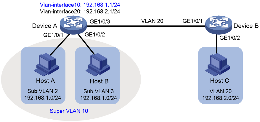
As shown in Figure 2:
· Users in VLAN 2 access the network through GigabitEthernet 1/0/1 on Device A. Users in VLAN 3 access the network through GigabitEthernet 1/0/2 on Device A. There are 30 users in VLAN 2 and 50 users in VLAN 3.
· GigabitEthernet 1/0/3 on Device A and GigabitEthernet 1/0/1 on Device B belong to VLAN 20.
· Endpoint users in VLAN 20 use the 192.168.2.0/24 subnet and use 192.168.2.1 as the gateway address.
Configure a super VLAN to meet the following requirements:
· Endpoint users in VLAN 2 and VLAN 3 use the 192.168.1.0/24 subnet to save IP address resources and use 192.168.1.1 as the gateway address.
· Endpoints users in VLANs 2, 3, and 20 are isolated at Layer 2 and can communicate at Layer 3.
Restrictions and guidelines
A super VLAN cannot contain physical interfaces. If a VLAN already contains physical interfaces, you cannot configure it as a super VLAN.
Procedures
Configuring Device A
# Create VLAN 10, and configure it as a super VLAN.
<DeviceA> system-view
[DeviceA] vlan 100
[DeviceA-vlan10] supervlan
[DeviceA-vlan10] quit
# Create VLAN 2. Assign GigabitEthernet 1/0/1 to VLAN 2.
[DeviceA] vlan 100
[DeviceA-vlan2] port gigabitethernet 1/0/1
[DeviceA-vlan2] quit
# Create VLAN 3. Assign GigabitEthernet 1/0/2 to VLAN 3.
[DeviceA] vlan 100
[DeviceA-vlan3] port gigabitethernet 1/0/2
[DeviceA-vlan3] quit
# Associate super VLAN 20 with sub-VLANs 2 and 3.
[DeviceA] vlan 100
[DeviceA-vlan10] subvlan 2 3
[DeviceA-vlan10] quit
# Assign an IP address to the VLAN interface for super VLAN 10, and enable local proxy on the VLAN interface.
[DeviceA] interface vlan-interface 10
[DeviceA-Vlan-interface10] ip address 192.168.1.1 24
[DeviceA-Vlan-interface10] local-proxy-arp enable
[DeviceA-Vlan-interface10] quit
# Create VLAN 20.
[DeviceA] vlan 100
[DeviceA-vlan20] quit
# Set the link type of GigabitEthernet 1/0/3 to trunk and assign it to VLAN 20. Remove it from VLAN 1.
[DeviceA] interface gigabitethernet 1/0/3
[DeviceA-GigabitEthernet1/0/3] port link-type trunk
[DeviceA-GigabitEthernet1/0/3] undo port trunk permit vlan 1
[DeviceA-GigabitEthernet1/0/3] port trunk permit vlan 20
[DeviceA-GigabitEthernet1/0/3] quit
# Assign an IP address to the VLAN interface for VLAN 20 .
[DeviceA] interface Vlan-interface 20
[DeviceA-Vlan-interface20] ip address 192.168.2.1 24
[DeviceA-Vlan-interface20] quit
# Save the configuration.
[DeviceA] save force
Configuring Device B
# Create VLAN 20.
[DeviceB] vlan 20
[DeviceB-vlan20] quit
# Set the link type of GigabitEthernet 1/0/1 to trunk and assign it to VLAN 20. Remove it from VLAN 1.
[DeviceB] interface gigabitethernet 1/0/1
[DeviceB-GigabitEthernet1/0/1] port link-type trunk
[DeviceB-GigabitEthernet1/0/1] undo port trunk permit vlan 1
[DeviceB-GigabitEthernet1/0/1] port trunk permit vlan 20
[DeviceB-GigabitEthernet1/0/1] quit
# Assign GigabitEthernet 1/0/2 to VLAN 20.
[DeviceB] vlan 20
[DeviceB-vlan20] port gigabitethernet 1/0/2
[DeviceB-vlan20] quit
# Save the configuration.
[DeviceB] save force
Verifying the configuration
# Display information about super VLANs on Device A.
<DeviceA> display supervlan
Super VLAN ID: 10
Sub-VLAN ID: 2-3
VLAN ID: 10
VLAN type: Static
It is a super VLAN.
Route interface: Configured
IPv4 address: 192.168.1.1
IPv4 subnet mask: 255.255.255.0
Description: VLAN 0010
Name: VLAN 0010
Tagged ports: None
Untagged ports: None
VLAN ID: 2
VLAN type: Static
It is a sub-VLAN.
Route interface: Configured
IPv4 address: 192.168.1.1
IPv4 subnet mask: 255.255.255.0
Description: VLAN 0002
Name: VLAN 0002
Tagged ports: None
Untagged ports:
GigabitEthernet1/0/1
VLAN ID: 3
VLAN type: Static
It is a sub-VLAN.
Route interface: Configured
IPv4 address: 192.168.1.1
IPv4 subnet mask: 255.255.255.0
Description: VLAN 0003
Name: VLAN 0003
Tagged ports: None
Untagged ports:
GigabitEthernet1/0/2
# Display information about VLAN 20 on Device A.
<DeviceA> display vlan 20
VLAN ID: 20
VLAN type: Static
Route interface: Configured
IPv4 address: 192.168.2.1
IPv4 subnet mask: 255.255.255.0
Description: VLAN 0020
Name: VLAN 0020
Tagged ports:
GigabitEthernet1/0/3
Untagged ports: None
# Display information about VLAN 20 on Device B.
<DeviceA> display vlan 20
VLAN ID: 20
VLAN type: Static
Route interface: Not configured
Description: VLAN 0020
Name: VLAN 0020
Tagged ports:
GigabitEthernet1/0/1
Untagged ports:
GigabitEthernet1/0/2
Configuration files
· Device A:
#
vlan 2
#
vlan 3
#
vlan 10
supervlan
subvlan 2 3
#
vlan 20
#
interface Vlan-interface10
ip address 192.168.1.1 255.255.255.0
local-proxy-arp enable
#
interface Vlan-interface20
ip address 192.168.2.1 255.255.255.0
#
interface GigabitEthernet1/0/1
port link-mode bridge
port access vlan 2
#
interface GigabitEthernet1/0/2
port link-mode bridge
port access vlan 3
#
interface GigabitEthernet1/0/3
port link-mode bridge
port link-type trunk
undo port trunk permit vlan 1
port trunk permit vlan 20
· Device B:
#
vlan 20
#
interface GigabitEthernet1/0/1
port link-mode bridge
port link-type trunk
undo port trunk permit vlan 1
port trunk permit vlan 20
#
interface GigabitEthernet1/0/2
port link-mode bridge
port access vlan 20
#
Related documentation
· Super VLAN configuration in the Layer 2—Ethernet switching configuration guide for the device.
· Super VLAN commands in the Layer 2—Ethernet switching command reference for the device.
Configuring voice VLANs
Introduction
The following information uses an example to describe the basic procedure for configuring voice VLANs.
Network configuration
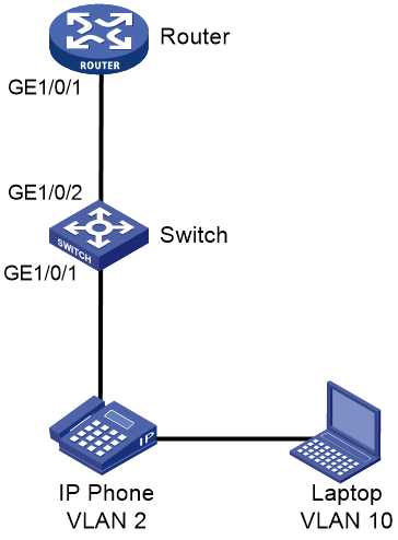
To ensure that voice traffic can be preferentially forwarded, you must separate the addresses of IP phones from those of laptops. Assign the subnet 192.168.2.0 to IP phones and assign the IP phones to VLAN 2. Assign the subnet 192.168.10.0 to laptops and assign the laptops to VLAN 10. Router acts as a DHCP server to allocate IP addresses to IP phones and laptops.
Procedures
Configuring Switch
# Enable PoE to supply power to phones.
<Switch> system-view
[Switch] interface gigabitethernet 1/0/1
[Switch-GigabitEthernet1/0/1] poe enable
[Switch-GigabitEthernet1/0/1] quit
# Create VLAN 2 for phones and VLAN 10 for laptops.
[Switch] vlan 2
[Switch-vlan2] quit
[Switch] vlan 10
[Switch-vlan10] quit
# Configure MAC addresses with prefix 6ca8-4900-0000 for voice packet identification.
[Switch] voice-vlan mac-address 6ca8-4900-0000 mask ffff-ff00-0000 description avaya
# Configure GigabitEthernet 1/0/1 as a hybrid port, and enable the voice VLAN feature on it.
[Switch] interface gigabitethernet 1/0/1
[Switch-GigabitEthernet1/0/1] port link-type hybrid
[Switch-GigabitEthernet1/0/1] voice-vlan 2 enable
# Configure VLAN 10, to which laptops belong.
[Switch-GigabitEthernet1/0/1] port hybrid pvid vlan 10
[Switch-GigabitEthernet1/0/1] port hybrid vlan 10 untagged
[SWITCH-GigabitEthernet1/0/1] quit
# Assign interface GigabitEthernet 1/0/2 (which connects to the DHCP server) to VLANs 2 and 10.
[Switch] interface gigabitethernet 1/0/2
[Switch-GigabitEthernet1/0/2] port link-type trunk
[Switch-GigabitEthernet1/0/2] port trunk permit vlan 2 10
[Switch-GigabitEthernet1/0/2] quit
# Save the configuration.
[Switch] save force
Configuring Router
# Create VLAN 2 and VLAN10, and their VLAN interfaces. Assign IP addresses to the VLAN interfaces.
<Router> system-view
[Router] vlan 2
[Router-vlan2] quit
[Router] vlan 10
[Router-vlan10] quit
[Router] interface Vlan-interface 2
[Router-Vlan-interface2] ip address 192.168.2.1 255.255.255.0
[Router-Vlan-interface2] quit
[Router] interface Vlan-interface 10
[Router-Vlan-interface10] ip address 192.168.10.1 255.255.255.0
[Router-Vlan-interface10] quit
# Assign interface GigabitEthernet 1/0/1 (which connects to Switch) to VLANs 2 and 10.
[Router] interface GigabitEthernet 1/0/1
[Router-GigabitEthernet1/0/1] port link-type trunk
[Router-GigabitEthernet1/0/1] port trunk permit vlan 2 10
[Router-GigabitEthernet1/0/1] quit
# Enable the DHCP service.
[Router] dhcp enable
# Configure the DHCP address pool for VLAN 2, which contains phones.
[Router] dhcp server ip-pool vlan2
[Router-dhcp-pool-vlan2] network 192.168.2.0 mask 255.255.255.0
[Router-dhcp-pool-vlan2] gateway-list 192.168.2.1
[Router-dhcp-pool-vlan2] quit
# Configure the DHCP address pool for VLAN 10, which contains laptops.
[Router] dhcp server ip-pool vlan10
[Router-dhcp-pool-vlan10] network 192.168.10.0 mask 255.255.255.0
[Router-dhcp-pool-vlan10] gateway-list 192.168.10.1
[Router-dhcp-pool-vlan10] dns-list 114.114.114.114
[Router-dhcp-pool-vlan10] quit
# Save the configuration.
[Router] save force
Verifying the configuration
# On Switch, verify that phones are assigned to VLAN 2.
<Switch> display mac-address
MAC Address VLAN ID STATE Port/Nickname AGING
3897-d630-676b 10 Learned GE1/0/2 Y
3897-d630-676b 2 Learned GE1/0/2 Y
6ca8-4986-6d59 2 Learned GE1/0/1 Y
0068-eb95-3683 10 Learned GE1/0/1 Y
# Verify that the voice VLAN configuration takes effect.
<Switch> display voice-vlan mac-address
Oui Address Mask Description
0003-6b00-0000 ffff-ff00-0000 Cisco phone
00e0-7500-0000 ffff-ff00-0000 Polycom phone
6ca8-4900-0000 ffff-ff00-0000 avaya
# Verify that the voice VLAN assignment mode is auto.
<Switch> display voice-vlan state
Current Voice VLANs: 1
Voice VLAN security mode: Security
Voice VLAN aging time: 1440 minutes
Voice VLAN enabled port and its mode:
PORT VLAN MODE COS DSCP
--------------------------------------------------------------------
GE1/0/1 2 AUTO 6 46
# On the DHCP server, view the IP addresses assigned to phones and laptops.
%Sep 1 09:19:59:333 2021 DHCP DHCPS/5/DHCPS_ALLOCATE_IP: DHCP server information: Server IP = 192.168.2.1, DHCP client IP = 192.168.2.2, DHCP client hardware address = 6ca8-4986-6d59, DHCP client lease = 86400.
<Router> display dhcp server ip-in-use all
Pool utilization: 0.59%
IP address Client-identifier/ Lease expiration Type
Hardware address
192.168.2.2 6ca8-4986-6d59 Aug 31 2021 09:19:59 Auto:COMMITTED
192.168.10.4 0068-eb95-3683 Aug 31 2021 09:19:42 Auto:COMMITTED
Configuration files
· Switch:
#
voice-vlan mac-address 6ca8-4900-0000 mask ffff-ff00-0000 description avaya
#
vlan 2
#
vlan 10
#
interface GigabitEthernet1/0/1
port link-mode bridge
port link-type hybrid
port hybrid vlan 10 untagged
port hybrid pvid vlan 10
voice-vlan 2 enable
poe enable
#
interface GigabitEthernet1/0/2
port link-mode bridge
port link-type trunk
port trunk permit vlan 2 10
· Router:
#
vlan 2
#
vlan 10
#
dhcp server ip-pool vlan2
gateway-list 192.168.2.1
network 192.168.2.0 255.255.255.0
#
dhcp server ip-pool vlan10
gateway-list 192.168.10.1
network 192.168.10.0 255.255.255.0
dns-list 114.114.114.114
#
interface Vlan-interface2
ip address 192.168.2.1 255.255.255.0
#
interface Vlan-interface10
ip address 192.168.10.1 255.255.255.0
#
interface GigabitEthernet1/0/1
port link-mode bridge
port link-type trunk
port trunk permit vlan 2 10
Related documentation
· Voice VLAN configuration in the Layer 2—Ethernet switching configuration guide for the device.
· Voice VLAN commands in the Layer 2—Ethernet switching command reference for the device.
Configuring private VLAN
Introduction
The following information uses an example to describe the basic procedure for configuring private VLAN.
Network configuration
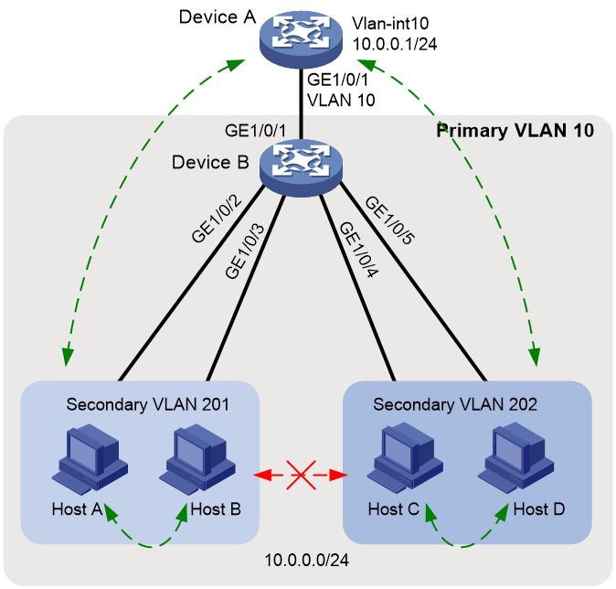
As shown in Figure 3:
· Device A on the aggregation layer assigns VLAN 10 to Device B on the access layer. The gateway interface (VLAN-interface 10) can communicate with all users, so that users can access Internet through Device A. All users attached to Device B are on the subnet 10.0.0.0/24.
· Hosts A and B belong to the sales department. Hosts C and D belong to the financial department. To ensure security, isolate different departments at Layer 2, and allow users in the same department to communicate with each other.
Because Device A cannot allocate more VLANs to Device B, configure the private VLAN feature to meet the following requirements:
· Device A only needs to recognize VLAN 10.
· In primary VLAN 10, Device B allocates different secondary VLANs to different departments, so these departments are isolated at Layer 2.
Restrictions and guidelines
· Configure the private VLAN feature only on the access device, Device B.
· The system default VLAN (VLAN 1) does not support private VLAN settings.
Procedures
Configuring Device B
# Configure VLAN 10 as the primary VLAN.
<DeviceB> system-view
[DeviceB] vlan 10
[DeviceB-vlan10] private-vlan primary
[DeviceB-vlan10] quit
# Create secondary VLANs 201 and 202.
[DeviceB] vlan 201 to 202
# Associate secondary VLANs 201 and 202 with the primary VLAN 10.
[DeviceB] vlan 10
[DeviceB-vlan10] private-vlan secondary 201 to 202
[DeviceB-vlan10] quit
# Configure the uplink port GigabitEthernet 1/0/1 to operate in promiscuous mode in VLAN 10.
[DeviceB] interface gigabitethernet 1/0/1
[DeviceB-GigabitEthernet1/0/1] port private-vlan 10 promiscuous
[DeviceB-GigabitEthernet1/0/1] quit
# Assign the downlink ports GigabitEthernet 1/0/2 and GigabitEthernet 1/0/3 to VLAN 201, and assign GigabitEthernet 1/0/4 and GigabitEthernet 1/0/5 to VLAN 202. Configure them to operate in host mode.
[DeviceB] interface range gigabitethernet 1/0/2 to gigabitethernet 1/0/3
[DeviceB-if-range] port access vlan 201
[DeviceB-if-range] port private-vlan host
[DeviceB-if-range] quit
[DeviceB] interface range gigabitethernet 1/0/4 to gigabitethernet 1/0/5
[DeviceB-if-range] port access vlan 202
[DeviceB-if-range] port private-vlan host
[DeviceB-if-range] quit
# Save the configuration.
[DeviceB] save force
Configuring Device A
# Create VLAN 10. Assign GigabitEthernet 1/0/1 to VLAN 10.
<DeviceA> system-view
[DeviceA] vlan 100
[DeviceA-vlan10] quit
[DeviceA] interface gigabitethernet 1/0/1
[DeviceA-GigabitEthernet1/0/1] port access vlan 10
[DeviceA-GigabitEthernet1/0/1] quit
# Configure VLAN-interface 10, which is to act as the gateway.
[DeviceA] interface vlan-interface 10
[DeviceA-Vlan-interface10] ip address 10.0.0.1 24
[DeviceA-Vlan-interface10] quit
# Save the configuration.
[DeviceA] save force
Verifying the configuration
# Verify that you can ping any user from Device A. View the ARP table to verify that all users belong to VLAN 10.
[DeviceA] display arp
Type: S-Static D-Dynamic O-Openflow R-Rule M-Multiport I-Invalid
IP address MAC address VLAN/VSI name Interface Aging Type
10.0.0.2 0e9e-0671-0302 10 GE1/0/1 1062 D
10.0.0.3 0e9e-09f7-0402 10 GE1/0/1 1052 D
10.0.0.4 0e9e-0d94-0502 10 GE1/0/1 1164 D
10.0.0.5 0e9e-1263-0602 10 GE1/0/1 1109 D
# Display the private VLAN configuration on Device B.
<DeviceB> display private-vlan
Primary VLAN ID: 10
Secondary VLAN ID: 201-202
VLAN ID: 10
VLAN type: Static
Private VLAN type: Primary
Route interface: Not configured
Description: VLAN 0010
Name: VLAN 0010
Tagged ports:
None
Untagged ports:
GigabitEthernet1/0/1(U) GigabitEthernet1/0/2(U)
GigabitEthernet1/0/3(U) GigabitEthernet1/0/4(U)
GigabitEthernet1/0/5(U)
VLAN ID: 201
VLAN type: Static
Private VLAN type: Secondary
Route interface: Not configured
Description: VLAN 0201
Name: VLAN 0201
Tagged ports:
None
Untagged ports:
GigabitEthernet1/0/1(U) GigabitEthernet1/0/2(U)
GigabitEthernet1/0/3(U)
VLAN ID: 202
VLAN type: Static
Private VLAN type: Secondary
Route interface: Not configured
Description: VLAN 0202
Name: VLAN 0202
Tagged ports:
None
Untagged ports:
GigabitEthernet1/0/1(U) GigabitEthernet1/0/4(U)
GigabitEthernet1/0/5(U)
The output shows that GigabitEthernet 1/0/1 in promiscuous mode and GigabitEthernet 1/0/2 through GigabitEthernet 1/0/5 in host mode all allow packets to pass through untagged.
# Verify that Host A and Host B can ping each other, and Host C and Host D can ping each other. Verify that Host A or B cannot ping Host C or D.
Configuration files
· Device A:
#
vlan 10
#
interface Vlan-interface10
ip address 10.0.0.1 255.255.255.0
#
interface GigabitEthernet1/0/1
port link-mode bridge
port access vlan 10
#
· Device B:
#
vlan 10
private-vlan primary
private-vlan secondary 201 to 202
#
vlan 201 to 202
#
interface GigabitEthernet1/0/1
port link-mode bridge
port link-type hybrid
undo port hybrid vlan 1
port hybrid vlan 10 201 to 202 untagged
port hybrid pvid vlan 10
port private-vlan 10 promiscuous
#
interface GigabitEthernet1/0/2
port link-mode bridge
port link-type hybrid
undo port hybrid vlan 1
port hybrid vlan 10 201 untagged
port hybrid pvid vlan 201
port private-vlan host
#
interface GigabitEthernet1/0/3
port link-mode bridge
port link-type hybrid
undo port hybrid vlan 1
port hybrid vlan 10 201 untagged
port hybrid pvid vlan 201
port private-vlan host
#
interface GigabitEthernet1/0/4
port link-mode bridge
port link-type hybrid
undo port hybrid vlan 1
port hybrid vlan 10 202 untagged
port hybrid pvid vlan 202
port private-vlan host
#
interface GigabitEthernet1/0/5
port link-mode bridge
port link-type hybrid
undo port hybrid vlan 1
port hybrid vlan 10 202 untagged
port hybrid pvid vlan 202
port private-vlan host
#
Related documentation
· Private VLAN configuration in the Layer 2—Ethernet switching configuration guide for the device.
· Private VLAN commands in the Layer 2—Ethernet switching command reference for the device.