- Table of Contents
-
- H3C Campus Fixed-Port Switches CLI-Based Quick Start Configuration Guide-6W101
- 01-H3C Devices CLI Reference
- 02-Login Management Quick Start Configuration Guide
- 03-Configuration File Management Quick Start Configruation Guide
- 04-Software Upgrade Quick Start Configuration Guide
- 05-Device Management Quick Start Configuration Guide
- 06-NTP Quick Start Configuration Guide
- 07-RBAC Quick Start Configuration Guide
- 08-IRF Quick Start Configuration Guide
- 09-Ethernet Interface Quick Start Configuration Guide
- 10-VLAN Quick Start Configuration Guide
- 11-Port Isolation Quick Start Configuration Guide
- 12-Loop Detection Quick Start Configuration Guide
- 13-QinQ Quick Start Configuration Guide
- 14-MAC Address Table Quick Start Configuration Guide
- 15-Ethernet Link Aggregation Quick Start Configuration Guide
- 16-Spanning Tree Quick Start Configuration Guide
- 17-DHCP Quick Start Configuration Guide
- 18-OSPF Quick Start Configuration Guide
- 19-Static Routing Quick Start Configuration Guide
- 20-Basic RIP Quick Start Configuration Guide
- 21-PBR Quick Start Configuration Guide
- 22-IGMP Snooping Quick Start Configuration Guide
- 23-Packet Filtering Quick Start Configuration Guide
- 24-QoS Quick Start Configuration Guide
- 25-IP Source Guard Quick Start Configuration Guide
- 26-SSH Quick Start Configuration Guide
- 27-Port Security Quick Start Configuration Guide
- 28-VRRP Quick Start Configuration Guide
- 29-PoE Quick Start Configuration Guide
- 30-Mirroring Quick Start Configuration Guide
- 31-Information Center Quick Start Configuration Guide
- 32-SNMP Quick Start Configuration Guide
- 33-LAN Networks Quick Start Configuration Guide
- Related Documents
-
| Title | Size | Download |
|---|---|---|
| 18-OSPF Quick Start Configuration Guide | 166.14 KB |
OSPF Quick Start Configuration Guide
Copyright © 2022 New H3C Technologies Co., Ltd. All rights reserved.
No part of this manual may be reproduced or transmitted in any form or by any means without prior written consent of New H3C Technologies Co., Ltd.
Except for the trademarks of New H3C Technologies Co., Ltd., any trademarks that may be mentioned in this document are the property of their respective owners.
The information in this document is subject to change without notice.
Contents
Configuring OSPF route redistribution
Configuring basic OSPF in a single area
Configuring basic OSPF across multiple areas
Configuring OSPF route redistribution
Introduction
The following example describes the basic procedure to configure OSPF route redistribution.
Network configuration
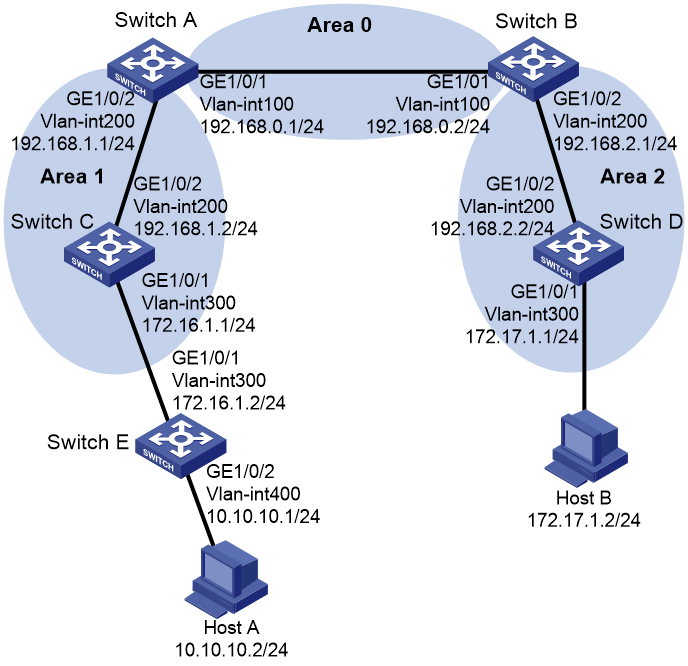
As shown in Figure 1, Switch A, Switch B, Switch C, and Switch D run OSPF. Switch C and Switch E are configured with static routes. The AS is split into three areas. Configure the network to meet the following requirements:
· Switch A and Switch B act as ABRs.
· Switch C acts as an ASBR to redistribute external routes (static routes) and correctly advertise routes within the AS.
Data preparation
|
Device |
Router ID |
Interface and IP address |
Subnet and OSPF area |
|
Switch A |
1.1.1.1 |
Physical interface: GE1/0/1 VLAN: 100 IP address: 192.168.0.1/24 |
Subnet: 192.168.0.0/24 OSPF area: area 0 |
|
Physical interface: GE1/0/2 VLAN: 200 IP address: 192.168.1.1/24 |
Subnet: 192.168.1.0/24 OSPF area: area 1 |
||
|
Switch B |
2.2.2.2 |
Physical interface: GE1/0/1 VLAN: 100 IP address: 192.168.0.2/24 |
Subnet: 192.168.0.0/24 OSPF area: area 0 |
|
Physical interface: GE1/0/2 VLAN: 200 IP address: 192.168.2.1/24 |
Subnet: 192.168.2.0/24 OSPF area: area 2 |
||
|
Switch C |
3.3.3.3 |
Physical interface: GE1/0/1 VLAN: 300 IP address: 172.16.1.1/24 |
Subnet: 172.16.1.0/24 OSPF area: area 1 |
|
Physical interface: GE1/0/2 VLAN: 200 IP address: 192.168.1.2/24 |
Subnet: 192.168.1.0/24 OSPF area: area 1 |
||
|
Switch D |
4.4.4.4 |
Physical interface: GE1/0/1 VLAN: 300 IP address: 172.17.1.1/24 |
Subnet: 172.17.1.0/24 OSPF area: area 2 |
|
Physical interface: GE1/0/2 VLAN: 200 IP address: 192.168.2.2/24 |
Subnet: 192.168.2.0/24 OSPF area: area 2 |
||
|
Switch E |
N/A |
Physical interface: GE1/0/1 VLAN: 300 IP address: 172.16.1.2/24 |
Subnet: 172.16.1.0/24 |
|
Physical interface: GE1/0/2 VLAN: 400 IP address: 10.10.10.1/24 |
Subnet: 10.10.10.0/24 |
||
|
Host A |
N/A |
IP address: 10.10.10.2/24 |
Subnet: 10.10.10.0/24 |
|
Host B |
N/A |
IP address: 172.17.1.2/24 |
Subnet: 172.17.1.0/24 |
Procedure
1. Configure Switch A.
# Create VLAN 100 and assign GE1/0/1 to VLAN 100.
<Switch A> system-view
[Switch A] vlan 100
[Switch A-vlan100] port gigabitethernet 1/0/1
[Switch A-vlan100] quit
# Create VLAN 200 and assign GE1/0/2 to VLAN 200.
[Switch A] vlan 200
[Switch A-vlan200] port gigabitethernet 1/0/2
[Switch A-vlan200] quit
# Assign IP address 192.168.0.1/24 to VLAN-interface 100 and IP address 192.168.1.1/24 to VLAN-interface 200.
[Switch A] interface vlan 100
[Switch A-Vlan-interface100] ip address 192.168.0.1 255.255.255.0
[Switch A-Vlan-interface100] quit
[Switch A] interface vlan 200
[Switch A-Vlan-interface200] ip address 192.168.1.1 255.255.255.0
[Switch A-Vlan-interface200] quit
# Configure 1.1.1.1 as the global router ID for Switch A.
[Switch A] router id 1.1.1.1
# Enable OSPF process 1, create area 0, and then advertise subnet 192.168.0.0/24.
[Switch A] ospf 1
[Switch A-ospf-1] area 0
[Switch A-ospf-1-area-0.0.0.0] network 192.168.0.0 0.0.0.255
[Switch A-ospf-1-area-0.0.0.0] quit
# Create area 1, and then advertise subnet 192.168.1.0/24.
[Switch A-ospf-1] area 1
[Switch A-ospf-1-area-0.0.0.1] network 192.168.1.0 0.0.0.255
[Switch A-ospf-1] quit
# Save the configuration.
[Switch A] save force
# Create VLAN 100 and assign GE1/0/1 to VLAN 100.
<Switch B> system-view
[Switch B] vlan 100
[Switch B-vlan100] port gigabitethernet 1/0/1
[Switch B-vlan100] quit
# Create VLAN 200 and assign GE1/0/2 to VLAN 200.
[Switch B] vlan 200
[Switch B-vlan200] port gigabitethernet 1/0/2
[Switch B-vlan200] quit
# Assign IP address 192.168.0.2/24 to VLAN-interface 100 and IP address 192.168.2.1/24 to VLAN-interface 200.
[Switch B] interface vlan 100
[Switch B-Vlan-interface100] ip address 192.168.0.2 255.255.255.0
[Switch B-Vlan-interface100] quit
[Switch B] interface vlan 200
[Switch B-Vlan-interface200] ip address 192.168.2.1 255.255.255.0
[Switch B-Vlan-interface200] quit
# Configure 2.2.2.2 as the global router ID for Switch B.
[Switch B] router id 2.2.2.2
# Enable OSPF process 1, create area 0, and then advertise subnet 192.168.0.0/24.
[Switch B] ospf 1
[Switch B-ospf-1] area 0
[Switch B-ospf-1-area-0.0.0.0] network 192.168.0.0 0.0.0.255
[Switch B-ospf-1-area-0.0.0.0] quit
# Create area 2, and then advertise subnet 192.168.2.0/24.
[Switch B-ospf-1] area 2
[Switch B-ospf-1-area-0.0.0.2] network 192.168.2.0 0.0.0.255
[Switch B-ospf-1-area-0.0.0.2] quit
[Switch B-ospf-1] quit
# Save the configuration.
[Switch B] save force
3. Configure Switch C.
# Create VLAN 300 and assign GE1/0/1 to VLAN 300.
<Switch C> system-view
[Switch C] vlan 300
[Switch C-vlan300] port gigabitethernet 1/0/1
[Switch C-vlan300] quit
# Create VLAN 200 and assign GE1/0/2 to VLAN 200.
[Switch C] vlan 200
[Switch C-vlan200] port gigabitethernet 1/0/2
[Switch C-vlan200] quit
# Assign IP address 172.16.1.1/24 to VLAN-interface 300 and IP address 192.168.1.2/24 to VLAN-interface 200.
[Switch C] interface vlan 300
[Switch C-Vlan-interface300] ip address 172.16.1.1 255.255.255.0
[Switch C-Vlan-interface300] quit
[Switch C] interface vlan 200
[Switch C-Vlan-interface200] ip address 192.168.1.2 255.255.255.0
[Switch C-Vlan-interface200] quit
# Configure a static route destined for subnet 10.10.10.0/24 and the next hop of the route is 172.16.1.2.
[Switch C] ip route-static 10.10.10.0 24 172.16.1.2
# Configure 3.3.3.3 as the global router ID for Switch C.
[Switch C] router id 3.3.3.3
# Enable OSPF process 1, create area 1, and then advertise subnet 192.168.1.0/24 and subnet 172.16.1.0/24.
[Switch C] ospf 1
[Switch C-ospf-1] area 1
[Switch C-ospf-1-area-0.0.0.1] network 192.168.1.0 0.0.0.255
[Switch C-ospf-1-area-0.0.0.1] network 172.16.1.0 0.0.0.255
[Switch C-ospf-1-area-0.0.0.1] quit
# Enable OSPF to redistribute static routes.
[Switch C-ospf-1] import-route static
[Switch C-ospf-1] quit
# Save the configuration.
[Switch C] save force
4. Configure Switch D.
# Create VLAN 300 and assign GE1/0/1 to VLAN 300.
<Switch D> system-view
[Switch D] vlan 300
[Switch D-vlan300] port gigabitethernet 1/0/1
[Switch D-vlan300] quit
# Create VLAN 200 and assign GE1/0/2 to VLAN 200.
[Switch D] vlan 200
[Switch D-vlan200] port gigabitethernet 1/0/2
[Switch D-vlan200] quit
# Assign IP address 172.17.1.1/24 to VLAN-interface 300 and IP address 192.168.2.2/24 to VLAN-interface 200.
[Switch D] interface vlan 300
[Switch D-Vlan-interface300] ip address 172.17.1.1 255.255.255.0
[Switch D-Vlan-interface300] quit
[Switch D] interface vlan 200
[Switch D-Vlan-interface200] ip address 192.168.2.2 255.255.255.0
[Switch D-Vlan-interface200] quit
# Configure 4.4.4.4 as the global router ID for Switch D.
[Switch D] router id 4.4.4.4
# Enable OSPF process 1, create area 2, and then advertise subnet 192.168.2.0/24 and subnet 172.17.1.0/24.
[Switch D] ospf 1
[Switch D-ospf-1] area 2
[Switch D-ospf-1-area-0.0.0.2] network 192.168.2.0 0.0.0.255
[Switch D-ospf-1-area-0.0.0.2] network 172.17.1.0 0.0.0.255
[Switch D-ospf-1-area-0.0.0.2] quit
[Switch D-ospf-1] quit
# Save the configuration.
[Switch D] save force
5. Configure Switch E.
# Create VLAN 300 and assign GE1/0/1 to VLAN 300.
<Switch E> system-view
[Switch E] vlan 300
[Switch E-vlan300] port gigabitethernet 1/0/1
[Switch E-vlan300] quit
# Create VLAN 400 and assign GE1/0/2 to VLAN 400.
[Switch E] vlan 400
[Switch E-vlan400] port gigabitethernet 1/0/2
[Switch E-vlan400] quit
# Assign IP address 172.16.1.2/24 to VLAN-interface 300 and IP address 10.10.10.1/24 to VLAN-interface 400.
[Switch E] interface vlan 300
[Switch E-Vlan-interface300] ip address 172.16.1.2 255.255.255.0
[Switch E-Vlan-interface300] quit
[Switch E] interface vlan 400
[Switch E-Vlan-interface400] ip address 10.10.10.1 255.255.255.0
[Switch E-Vlan-interface400] quit
# Configure the default route and the next hop of the route is 172.16.1.1
[Switch E] ip route-static 0.0.0.0 0 172.16.1.1
# Save the configuration.
[Switch E] save force
Verifying the configuration
# Use the display ip routing-table command to view the routing table of Switch A.
[Switch A] display ip routing-table
Destinations : 20 Routes : 20
Destination/Mask Proto Pre Cost NextHop Interface
0.0.0.0/32 Direct 0 0 127.0.0.1 InLoop0
10.10.10.0/24 O_ASE2 150 1 192.168.1.2 Vlan200
127.0.0.0/8 Direct 0 0 127.0.0.1 InLoop0
127.0.0.0/32 Direct 0 0 127.0.0.1 InLoop0
127.0.0.1/32 Direct 0 0 127.0.0.1 InLoop0
127.255.255.255/32 Direct 0 0 127.0.0.1 InLoop0
172.16.1.0/24 O_INTRA 10 2 192.168.1.2 Vlan200
172.17.1.0/24 O_INTER 10 3 192.168.0.2 Vlan100
192.168.0.0/24 Direct 0 0 192.168.0.1 Vlan100
192.168.0.0/32 Direct 0 0 192.168.0.1 Vlan100
192.168.0.1/32 Direct 0 0 127.0.0.1 InLoop0
192.168.0.255/32 Direct 0 0 192.168.0.1 Vlan100
192.168.1.0/24 Direct 0 0 192.168.1.1 Vlan200
192.168.1.0/32 Direct 0 0 192.168.1.1 Vlan200
192.168.1.1/32 Direct 0 0 127.0.0.1 InLoop0
192.168.1.255/32 Direct 0 0 192.168.1.1 Vlan200
192.168.2.0/24 O_INTER 10 2 192.168.0.2 Vlan100
224.0.0.0/4 Direct 0 0 0.0.0.0 NULL0
224.0.0.0/24 Direct 0 0 0.0.0.0 NULL0
255.255.255.255/32 Direct 0 0 127.0.0.1 InLoop0
The output shows that Switch A has routes to 172.16.1.0, 172.17.1.0, and 192.168.2.0 and has static routes that are redistributed from other routing protocols.
# Check whether Host A can ping Host B successfully.
C:\Users\HostA>ping 172.17.1.2
The output shows that Host A can ping Host B successfully.
Configuration files
#
router id 1.1.1.1
#
ospf 1
area 0.0.0.0
network 192.168.0.0 0.0.0.255
area 0.0.0.1
network 192.168.1.0 0.0.0.255
#
interface Vlan-interface100
ip address 192.168.0.1 255.255.255.0
#
interface Vlan-interface200
ip address 192.168.1.1 255.255.255.0
#
interface GigabitEthernet1/0/1
port access vlan 100
#
interface GigabitEthernet1/0/2
port access vlan 200
#
· Switch B:
#
router id 2.2.2.2
#
ospf 1
area 0.0.0.0
network 192.168.0.0 0.0.0.255
area 0.0.0.2
network 192.168.2.0 0.0.0.255
#
interface Vlan-interface100
ip address 192.168.0.2 255.255.255.0
#
interface Vlan-interface200
ip address 192.168.2.1 255.255.255.0
#
interface GigabitEthernet1/0/1
port access vlan 100
#
interface GigabitEthernet1/0/2
port access vlan 200
#
· Switch C:
#
router id 3.3.3.3
#
ospf 1
area 0.0.0.1
network 192.168.1.0 0.0.0.255
network 172.16.1.0 0.0.0.255
#
interface Vlan-interface200
ip address 192.168.1.2 255.255.255.0
#
interface Vlan-interface300
ip address 172.16.1.1 255.255.255.0
#
interface GigabitEthernet1/0/1
port access vlan 300
#
interface GigabitEthernet1/0/2
port access vlan 200
#
· Switch D:
#
router id 4.4.4.4
#
ospf 1
area 0.0.0.2
network 192.168.2.0 0.0.0.255
network 172.17.1.0 0.0.0.255
#
interface Vlan-interface200
ip address 192.168.2.2 255.255.255.0
#
interface Vlan-interface300
ip address 172.17.1.1 255.255.255.0
#
interface GigabitEthernet1/0/1
port access vlan 300
#
interface GigabitEthernet1/0/2
port access vlan 200
#
· Switch E:
#
interface Vlan-interface200
ip address 10.10.10.1 255.255.255.0
#
interface Vlan-interface300
ip address 172.16.1.2 255.255.255.0
#
interface GigabitEthernet1/0/1
port access vlan 300
#
interface GigabitEthernet1/0/2
port access vlan 200
#
ip route-static 0.0.0.0 0 172.16.1.1
#
Related documentation
· OSPF configuration in the Layer 3—IP routing configuration guide for the device.
· OSPF commands in the Layer 3—IP routing command reference for the device.
Configuring basic OSPF in a single area
Introduction
The following example describes the procedure to configure basic OSPF in a single area.
Network configuration
As shown in Figure 2, Switch A and Switch B run OSPF. Configure the network to ensure that Host A and Host B can access each other through Switch A and Switch B.

Procedure
1. Configure Switch A.
# Create VLAN 10 and assign GE1/0/1 to VLAN 10.
<Switch A> system-view
[Switch A] vlan 10
[Switch A-vlan10] port gigabitethernet 1/0/1
[Switch A-vlan10] quit
# Create VLAN 20 and assign GE1/0/2 to VLAN 20.
[Switch A] vlan 20
[Switch A-vlan20] port gigabitethernet 1/0/2
[Switch A-vlan20] quit
# Assign IP address 192.168.10.1/24 to VLAN-interface 10 and IP address 192.168.20.1/24 to VLAN-interface 20.
[Switch A] interface vlan 10
[Switch A-Vlan-interface10] ip address 192.168.10.1 255.255.255.0
[Switch A-Vlan-interface10] quit
[Switch A] interface vlan 20
[Switch A-Vlan-interface20] ip address 192.168.20.1 255.255.255.0
[Switch A-Vlan-interface20] quit
# Configure 1.1.1.1 as the global router ID for Switch A.
[Switch A] router id 1.1.1.1
# Enable OSPF process 1, create area 0, and then advertise subnet 192.168.10.0/24 and subnet 192.168.20.0/24.
[Switch A] ospf 1
[Switch A-ospf-1] area 0
[Switch A-ospf-1-area-0.0.0.0] network 192.168.10.0 0.0.0.255
[Switch A-ospf-1-area-0.0.0.0] network 192.168.20.0 0.0.0.255
[Switch A-ospf-1-area-0.0.0.0] quit
[Switch A-ospf-1] quit
# Save the configuration.
[Switch A] save force
2. Configure Switch B.
# Create VLAN 30 and assign GE1/0/1 to VLAN 30.
<Switch B> system-view
[Switch B] vlan 30
[Switch B-vlan30] port gigabitethernet 1/0/1
[Switch B-vlan30] quit
# Create VLAN 20 and assign GE1/0/2 to VLAN 20.
[Switch B] vlan 20
[Switch B-vlan20] port gigabitethernet 1/0/2
[Switch B-vlan20] quit
# Assign IP address 192.168.30.1/24 to VLAN-interface 30 and IP address 192.168.20.2/24 to VLAN-interface 20.
[Switch B] interface vlan 30
[Switch B-Vlan-interface30] ip address 192.168.30.1 255.255.255.0
[Switch B-Vlan-interface30] quit
[Switch B] interface vlan 20
[Switch B-Vlan-interface20] ip address 192.168.20.2 255.255.255.0
[Switch B-Vlan-interface20] quit
# Configure 2.2.2.2 as the global router ID for Switch B.
[Switch B] router id 2.2.2.2
# Enable OSPF process 1, create area 0, and then advertise subnet 192.168.20.0/24 and subnet 192.168.30.0/24.
[Switch B] ospf 1
[Switch B-ospf-1] area 0
[Switch B-ospf-1-area-0.0.0.0] network 192.168.20.0 0.0.0.255
[Switch B-ospf-1-area-0.0.0.0] network 192.168.30.0 0.0.0.255
[Switch B-ospf-1-area-0.0.0.0] quit
[Switch B-ospf-1] quit
# Save the configuration.
[Switch B] save force
Verifying the configuration
# Use the display ospf peer command to view the OSPF neighbors of Switch A.
[Switch A] display ospf peer
OSPF Process 1 with Router ID 1.1.1.1
Neighbor Brief Information
Area: 0.0.0.0
Router ID Address Pri Dead-Time State Interface
2.2.2.2 192.168.20.2 1 30 Full/DR - Vlan20
# Use the display ospf routing command to view the OSPF routes of Switch A.
[Switch A] display ospf routing
OSPF Process 1 with Router ID 1.1.1.1
Routing Table
Topology base (MTID 0)
Routing for network
Destination Cost Type NextHop AdvRouter Area
192.168.10.0/24 1 Stub 0.0.0.0 192.168.20.1 0.0.0.0
192.168.30.0/24 2 Stub 192.168.20.2 192.168.20.2 0.0.0.0
192.168.20.0/24 1 Transit 0.0.0.0 192.168.20.1 0.0.0.0
# Use the display ip routing-table command to view the routing table of Switch A.
[Switch A] display ip routing-table
Destinations : 17 Routes : 17
Destination/Mask Proto Pre Cost NextHop Interface
0.0.0.0/32 Direct 0 0 127.0.0.1 InLoop0
127.0.0.0/8 Direct 0 0 127.0.0.1 InLoop0
127.0.0.0/32 Direct 0 0 127.0.0.1 InLoop0
127.0.0.1/32 Direct 0 0 127.0.0.1 InLoop0
127.255.255.255/32 Direct 0 0 127.0.0.1 InLoop0
192.168.10.0/24 Direct 0 0 192.168.10.1 Vlan10
192.168.10.0/32 Direct 0 0 192.168.10.1 Vlan10
192.168.10.1/32 Direct 0 0 127.0.0.1 InLoop0
192.168.10.255/32 Direct 0 0 192.168.10.1 Vlan10
192.168.20.0/24 Direct 0 0 192.168.20.1 Vlan20
192.168.20.0/32 Direct 0 0 192.168.20.1 Vlan20
192.168.20.1/32 Direct 0 0 127.0.0.1 InLoop0
192.168.20.255/32 Direct 0 0 192.168.20.1 Vlan20
192.168.30.0/24 O_INTRA 10 2 192.168.20.2 Vlan20
224.0.0.0/4 Direct 0 0 0.0.0.0 NULL0
224.0.0.0/24 Direct 0 0 0.0.0.0 NULL0
255.255.255.255/32 Direct 0 0 127.0.0.1 InLoop0
The output shows that Switch A has a route to 192.168.30.0/24.
# Check whether Host A can ping Host B successfully.
C:\Users\HostA>ping 192.168.30.2
The output shows that Host A can ping Host B successfully.
Configuration files
· Switch A:
#
router id 1.1.1.1
#
ospf 1
area 0.0.0.0
network 192.168.10.0 0.0.0.255
network 192.168.20.0 0.0.0.255
#
interface Vlan-interface10
ip address 192.168.10.1 255.255.255.0
#
interface Vlan-interface20
ip address 192.168.20.1 255.255.255.0
#
interface GigabitEthernet1/0/1
port access vlan 10
#
interface GigabitEthernet1/0/2
port access vlan 20
#
· Switch B:
#
router id 2.2.2.2
#
ospf 1
area 0.0.0.0
network 192.168.20.0 0.0.0.255
network 192.168.30.0 0.0.0.255
#
interface Vlan-interface20
ip address 192.168.20.2 255.255.255.0
#
interface Vlan-interface30
ip address 192.168.30.1 255.255.255.0
#
interface GigabitEthernet1/0/1
port access vlan 30
#
interface GigabitEthernet1/0/2
port access vlan 20
#
Related documentation
· OSPF configuration in the Layer 3—IP routing configuration guide for the device.
· OSPF commands in the Layer 3—IP routing command reference for the device.
Configuring basic OSPF across multiple areas
Introduction
The following example describes the procedure to configure basic OSPF across multiple areas.
Network configuration
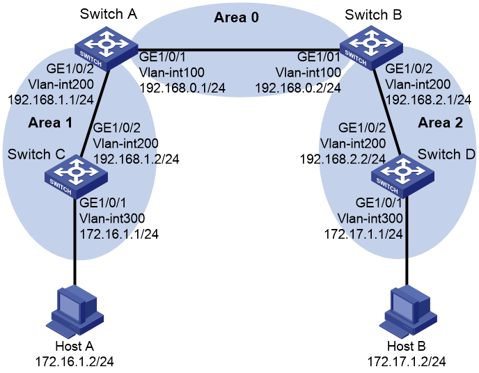
As shown in Figure 3, Switch A, Switch B, Switch C, and Switch D run OSPF. The AS is split into three areas. Switch A and Switch B act as ABRs. Configure the network to ensure that each switch can learn all of the routes in the AS.
Data preparation
|
Device |
Router ID |
Interface and IP address |
Subnet and OSPF area |
|
Switch A |
1.1.1.1 |
Physical interface: GE1/0/1 VLAN: 100 IP address: 192.168.0.1/24 |
Subnet: 192.168.0.0/24 OSPF area: area 0 |
|
Physical interface: GE1/0/2 VLAN: 200 IP address: 192.168.1.1/24 |
Subnet: 192.168.1.0/24 OSPF area: area 1 |
||
|
Switch B |
2.2.2.2 |
Physical interface: GE1/0/1 VLAN: 100 IP address: 192.168.0.2/24 |
Subnet: 192.168.0.0/24 OSPF area: area 0 |
|
Physical interface: GE1/0/2 VLAN: 200 IP address: 192.168.2.1/24 |
Subnet: 192.168.2.0/24 OSPF area: area 2 |
||
|
Switch C |
3.3.3.3 |
Physical interface: GE1/0/1 VLAN: 300 IP address: 172.16.1.1/24 |
Subnet: 172.16.1.0/24 OSPF area: area 1 |
|
Physical interface: GE1/0/2 VLAN: 200 IP address: 192.168.1.2/24 |
Subnet: 192.168.1.0/24 OSPF area: area 1 |
||
|
Switch D |
4.4.4.4 |
Physical interface: GE1/0/1 VLAN: 300 IP address: 172.17.1.1/24 |
Subnet: 172.17.1.0/24 OSPF area: area 2 |
|
Physical interface: GE1/0/2 VLAN: 200 IP address: 192.168.2.2/24 |
Subnet: 192.168.2.0/24 OSPF area: area 2 |
||
|
Host A |
N/A |
IP address: 172.16.1.2/24 |
Subnet: 172.16.1.0/24 |
|
Host B |
N/A |
IP address: 172.17.1.2/24 |
Subnet: 172.17.1.0/24 |
Procedure
1. Configure Switch A.
# Create VLAN 100 and assign GE1/0/1 to VLAN 100.
<Switch A> system-view
[Switch A] vlan 100
[Switch A-vlan100] port gigabitethernet 1/0/1
[Switch A-vlan100] quit
# Create VLAN 200 and assign GE1/0/2 to VLAN 200.
[Switch A] vlan 200
[Switch A-vlan200] port gigabitethernet 1/0/2
[Switch A-vlan200] quit
# Assign IP address 192.168.0.1/24 to VLAN-interface 100 and IP address 192.168.1.1/24 to VLAN-interface 200.
[Switch A] interface vlan 100
[Switch A-Vlan-interface100] ip address 192.168.0.1 255.255.255.0
[Switch A-Vlan-interface100] quit
[Switch A] interface vlan 200
[Switch A-Vlan-interface200] ip address 192.168.1.1 255.255.255.0
[Switch A-Vlan-interface200] quit
# Configure 1.1.1.1 as the global router ID for Switch A.
[Switch A] router id 1.1.1.1
# Enable OSPF process 1, create area 0, and then advertise subnet 192.168.0.0/24.
[Switch A] ospf 1
[Switch A-ospf-1] area 0
[Switch A-ospf-1-area-0.0.0.0] network 192.168.0.0 0.0.0.255
[Switch A-ospf-1-area-0.0.0.0] quit
# Create area 1, and then advertise subnet 192.168.1.0/24.
[Switch A-ospf-1] area 1
[Switch A-ospf-1-area-0.0.0.1] network 192.168.1.0 0.0.0.255
[Switch A-ospf-1-area-0.0.0.1] quit
[Switch A-ospf-1] quit
# Save the configuration.
[Switch A] save force
2. Configure Switch B.
# Create VLAN 100 and assign GE1/0/1 to VLAN 100.
<Switch B> system-view
[Switch B] vlan 100
[Switch B-vlan100] port gigabitethernet 1/0/1
[Switch B-vlan100] quit
# Create VLAN 200 and assign GE1/0/2 to VLAN 200.
[Switch B] vlan 200
[Switch B-vlan200] port gigabitethernet 1/0/2
[Switch B-vlan200] quit
# Assign IP address 192.168.0.2/24 to VLAN-interface 100 and IP address 192.168.2.1/24 to VLAN-interface 200.
[Switch B] interface vlan 100
[Switch B-Vlan-interface100] ip address 192.168.0.2 255.255.255.0
[Switch B-Vlan-interface100] quit
[Switch B] interface vlan 200
[Switch B-Vlan-interface200] ip address 192.168.2.1 255.255.255.0
[Switch B-Vlan-interface200] quit
# Configure 2.2.2.2 as the global router ID for Switch B.
[Switch B] router id 2.2.2.2
# Enable OSPF process 1, create area 0, and then advertise subnet 192.168.0.0/24.
[Switch B] ospf 1
[Switch B-ospf-1] area 0
[Switch B-ospf-1-area-0.0.0.0] network 192.168.0.0 0.0.0.255
[Switch B-ospf-1-area-0.0.0.0] quit
# Create area 2, and then advertise subnet 192.168.2.0/24.
[Switch B-ospf-1] area 2
[Switch B-ospf-1-area-0.0.0.2] network 192.168.2.0 0.0.0.255
[Switch B-ospf-1-area-0.0.0.2] quit
[Switch B-ospf-1] quit
# Save the configuration.
[Switch B] save force
3. Configure Switch C.
# Create VLAN 300 and assign GE1/0/1 to VLAN 300.
<Switch C> system-view
[Switch C] vlan 300
[Switch C-vlan300] port gigabitethernet 1/0/1
[Switch C-vlan300] quit
# Create VLAN 200 and assign GE1/0/2 to VLAN 200.
[Switch C] vlan 200
[Switch C-vlan200] port gigabitethernet 1/0/2
[Switch C-vlan200] quit
# Assign IP address 172.16.1.1/24 to VLAN-interface 300 and IP address 192.168.1.2/24 to VLAN-interface 200.
[Switch C] interface vlan 300
[Switch C-Vlan-interface300] ip address 172.16.1.1 255.255.255.0
[Switch C-Vlan-interface300] quit
[Switch C] interface vlan 200
[Switch C-Vlan-interface200] ip address 192.168.1.2 255.255.255.0
[Switch C-Vlan-interface200] quit
# Configure 3.3.3.3 as the global router ID for Switch C.
[Switch C] router id 3.3.3.3
# Enable OSPF process 1, create area 1, and then advertise subnet 192.168.1.0/24 and subnet 172.16.1.0/24.
[Switch C] ospf 1
[Switch C-ospf-1] area 1
[Switch C-ospf-1-area-0.0.0.1] network 192.168.1.0 0.0.0.255
[Switch C-ospf-1-area-0.0.0.1] network 172.16.1.0 0.0.0.255
[Switch C-ospf-1-area-0.0.0.1] quit
[Switch C-ospf-1] quit
# Save the configuration.
[Switch C] save force
4. Configure Switch D.
# Create VLAN 300 and assign GE1/0/1 to VLAN 300.
<Switch D> system-view
[Switch D] vlan 300
[Switch D-vlan300] port gigabitethernet 1/0/1
[Switch D-vlan300] quit
# Create VLAN 200 and assign GE1/0/2 to VLAN 200.
[Switch D] vlan 200
[Switch D-vlan200] port gigabitethernet 1/0/2
[Switch D-vlan200] quit
# Assign IP address 172.17.1.1/24 to VLAN-interface 300 and IP address 192.168.2.2/24 to VLAN-interface 200.
[Switch D] interface vlan 300
[Switch D-Vlan-interface300] ip address 172.17.1.1 255.255.255.0
[Switch D-Vlan-interface300] quit
[Switch D] interface vlan 200
[Switch D-Vlan-interface200] ip address 192.168.2.2 255.255.255.0
[Switch D-Vlan-interface200] quit
# Configure 4.4.4.4 as the global router ID for Switch D.
[Switch D] router id 4.4.4.4
# Enable OSPF process 1, create area 2, and then advertise subnet 192.168.2.0/24 and subnet 172.17.1.0/24.
[Switch D] ospf 1
[Switch D-ospf-1] area 2
[Switch D-ospf-1-area-0.0.0.2] network 192.168.2.0 0.0.0.255
[Switch D-ospf-1-area-0.0.0.2] network 172.17.1.0 0.0.0.255
[Switch D-ospf-1-area-0.0.0.2] quit
[Switch D-ospf-1] quit
# Save the configuration.
[Switch D] save force
Verifying the configuration
# Use the display ospf peer command to view the OSPF neighbors of Switch A.
[Switch A] display ospf peer
OSPF Process 1 with Router ID 1.1.1.1
Neighbor Brief Information
Area: 0.0.0.0
Router ID Address Pri Dead-Time State Interface
2.2.2.2 192.168.0.2 1 33 Full/DR Vlan100
Area: 0.0.0.1
Router ID Address Pri Dead-Time State Interface
3.3.3.3 192.168.1.2 1 34 Full/DR Vlan200
# Use the display ip routing-table command to view the routing table of Switch A.
[Switch A] display ip routing-table
Destinations : 19 Routes : 19
Destination/Mask Proto Pre Cost NextHop Interface
0.0.0.0/32 Direct 0 0 127.0.0.1 InLoop0
127.0.0.0/8 Direct 0 0 127.0.0.1 InLoop0
127.0.0.0/32 Direct 0 0 127.0.0.1 InLoop0
127.0.0.1/32 Direct 0 0 127.0.0.1 InLoop0
127.255.255.255/32 Direct 0 0 127.0.0.1 InLoop0
172.16.1.0/24 O_INTRA 10 2 192.168.1.2 Vlan200
172.17.1.0/24 O_INTER 10 3 192.168.0.2 Vlan100
192.168.0.0/24 Direct 0 0 192.168.0.1 Vlan100
192.168.0.0/32 Direct 0 0 192.168.0.1 Vlan100
192.168.0.1/32 Direct 0 0 127.0.0.1 InLoop0
192.168.0.255/32 Direct 0 0 192.168.0.1 Vlan100
192.168.1.0/24 Direct 0 0 192.168.1.1 Vlan200
192.168.1.0/32 Direct 0 0 192.168.1.1 Vlan200
192.168.1.1/32 Direct 0 0 127.0.0.1 InLoop0
192.168.1.255/32 Direct 0 0 192.168.1.1 Vlan200
192.168.2.0/24 O_INTER 10 2 192.168.0.2 Vlan100
224.0.0.0/4 Direct 0 0 0.0.0.0 NULL0
224.0.0.0/24 Direct 0 0 0.0.0.0 NULL0
255.255.255.255/32 Direct 0 0 127.0.0.1 InLoop0
The output shows that Switch A has routes to 172.16.1.0, 172.17.1.0, and 192.168.2.0.
# Check whether Host A can ping Host B successfully.
C:\Users\HostA>ping 172.17.1.2
The output shows that Host A can ping Host B successfully.
Configuration files
· Switch A:
#
router id 1.1.1.1
#
ospf 1
area 0.0.0.0
network 192.168.0.0 0.0.0.255
area 0.0.0.1
network 192.168.1.0 0.0.0.255
#
interface Vlan-interface100
ip address 192.168.0.1 255.255.255.0
#
interface Vlan-interface200
ip address 192.168.1.1 255.255.255.0
#
interface GigabitEthernet1/0/1
port access vlan 100
#
interface GigabitEthernet1/0/2
port access vlan 200
#
· Switch B:
#
router id 2.2.2.2
#
ospf 1
area 0.0.0.0
network 192.168.0.0 0.0.0.255
area 0.0.0.2
network 192.168.2.0 0.0.0.255
#
interface Vlan-interface100
ip address 192.168.0.2 255.255.255.0
#
interface Vlan-interface200
ip address 192.168.2.1 255.255.255.0
#
interface GigabitEthernet1/0/1
port access vlan 100
#
interface GigabitEthernet1/0/2
port access vlan 200
#
· Switch C:
#
router id 3.3.3.3
#
ospf 1
area 0.0.0.1
network 192.168.1.0 0.0.0.255
network 172.16.1.0 0.0.0.255
#
interface Vlan-interface200
ip address 192.168.1.2 255.255.255.0
#
interface Vlan-interface300
ip address 172.16.1.1 255.255.255.0
#
interface GigabitEthernet1/0/1
port access vlan 300
#
interface GigabitEthernet1/0/2
port access vlan 200
#
· Switch D:
#
router id 4.4.4.4
#
ospf 1
area 0.0.0.2
network 192.168.2.0 0.0.0.255
network 172.17.1.0 0.0.0.255
#
interface Vlan-interface200
ip address 192.168.2.2 255.255.255.0
#
interface Vlan-interface300
ip address 172.17.1.1 255.255.255.0
#
interface GigabitEthernet1/0/1
port access vlan 300
#
interface GigabitEthernet1/0/2
port access vlan 200
#
Related documentation
· OSPF configuration in the Layer 3—IP routing configuration guide for the device.
· OSPF commands in the Layer 3—IP routing command reference for the device.
