- Table of Contents
-
- H3C S9500 Operation Manual-Release1648[v1.24]-08 System Volume
- 00-1Cover
- 01-Command Line Interface Configuration
- 02-Login and User Interface Configuration
- 03-FTP and TFTP Configuration
- 04-HA Configuration
- 05-NQA Configuration
- 06-NetStream Configuration
- 07-NTP Configuration
- 08-RMON Configuration
- 09-SNMP Configuration
- 10-Packet Statistics Accounting Configuration
- 11-Device Management Configuration
- 12-Configuration File Management Configuration
- 13-File System Management Configuration
- 14-Cluster Management Configuration
- 15-System Maintenance and Debugging Configuration
- 16-Information Center Configuration
- 17-PoE Configuration
- 18-Clock Module Configuration
- 19-ACSEI Server Configuration
- 20-OAP Module Configuration
- Related Documents
-
| Title | Size | Download |
|---|---|---|
| 07-NTP Configuration | 253.75 KB |
Table of Contents
1.1.2 Basic Operating Principle of NTP
1.2.1 Configuring NTP Operating Mode
1.2.2 Configuring NTP ID Authentication
1.2.3 Setting NTP Authentication Key
1.2.4 Setting Specified Key as Reliable
1.2.5 Designating an Interface to Transmit NTP Messages
1.2.6 Setting NTP Master Clock
1.2.7 Disabling an Interface from Receiving NTP Messages
1.2.8 Setting Authority to Access a Local Switch
1.2.9 Setting Maximum Local Sessions
1.3 Displaying and Debugging NTP
1.4 NTP Configuration Examples
1.4.1 Configuring an NTP Server
1.4.2 NTP Peer Configuration Example
1.4.3 Configure NTP Broadcast Mode
1.4.4 Configure NTP Multicast Mode
1.4.5 Configure Authentication-Enabled NTP Server Mode
Chapter 1 NTP Configuration
When configuring NTP, go to these sections for information you are interested in:
l Introduction to NTP
l Displaying and Debugging NTP
1.1 Introduction to NTP
1.1.1 NTP Functions
As the network topology gets more and more complex, it becomes important to synchronize the clocks of the equipment on the whole network. Network Time Protocol (NTP) is the TCP/IP that advertises the accurate time throughout the network.
NTP ensures the consistency of the following applications:
l For the increment backup between the server and the client, NTP ensures the clock synchronization between the two systems.
l For multiple systems that coordinate to process a complex event, NTP ensures them to reference the same clock and guarantee the right order of the event.
l Guarantee the normal operation of the inter-system Remote Procedure Call (RPC).
l Record for an application when a user logs in to a system, a file is modified, or some other operation is performed.
1.1.2 Basic Operating Principle of NTP
The following figure illustrates the basic operating principle of NTP:
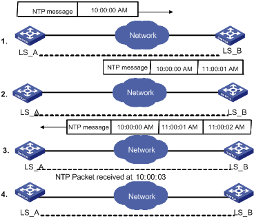
Figure 1-1 Basic operating principle of NTP
In the figure above, Switch A and Switch B are connected through the Ethernet port. They have independent system clocks. Before implement automatic clock synchronization on both switches, we assume that:
l Before synchronizing the system clocks on Switch A and B, the clock on Switch A is set to 10:00:00am, and that on B is set to 11:00:00am.
l Switch B serves as an NTP time server. That is, Switch A synchronizes the local clock with the clock of B.
l It takes one second to transmit a data packet from either A or B to the opposite end.
The system clocks are synchronized as follows:
l Switch A sends an NTP packet to Switch B. The packet carries the timestamp 10:00:00am (T1) that tells when it left Switch A.
l When the NTP packet arrives at Switch B, Switch B adds a local timestamp 11:00:01am (T2) to it.
l When the NTP packet leaves Switch B, Switch B adds another local timestamp 11:00:02am (T3) to it.
l When Switch A receives the acknowledgement packet, it adds a new timestamp 10:00:03am (T4) to it.
Now, Switch A collects enough information to calculate the following two important parameters:
l The delay for a round trip of an NTP packet traveling between Switch A and B: Delay= (T4-T1) - (T3-T2).
l Offset of Switch A clock relative to Switch B clock: offset= ( (T2-T1) + (T4-T3) ) /2.
In this way, Switch A uses the above-mentioned information to set the local clock and synchronize it with the clock on Switch B.
The operating principle of NTP is briefly introduced above. For details, refer to RFC1305.
1.2 NTP Configuration
NTP is used for time synchronization throughout a network. The following sections describe the NTP configuration tasks.
l Configuring NTP Operating Mode
l Configuring NTP ID Authentication
l Setting NTP Authentication Key
l Setting Specified Key as Reliable
l Designating an Interface to Transmit NTP Messages
l Disabling an Interface from Receiving NTP Messages
l Setting Authority to Access a Local Switch
l Setting Maximum Local Sessions
1.2.1 Configuring NTP Operating Mode
You can set the NTP operating mode of a Switch according to its location in the network and the network structure. The following settings are for your reference:
l If you set a remote server as the time server of the local equipment, the local Switch works as an NTP Client.
l If you set a remote server as a peer of the local Switch, the local equipment operates in Symmetric Active mode.
l If you configure an interface on the local Switch to transmit NTP broadcast packets, the local Switch will operate in Broadcast mode.
l If you configure an interface on the local Switch to receive NTP broadcast packets, the local Switch will operate in Broadcast Client mode.
l If you configure an interface on the local Switch to transmit NTP multicast packets, the local Switch will operate in Multicast mode.
l If you configure an interface on the local Switch to receive NTP multicast packets, the local Switch will operate in Multicast Client mode.
To configure NTP:
l Configure NTP server mode
l Configure NTP peer mode
l Configure NTP broadcast server mode
l Configure NTP broadcast client mode
l Configure NTP multicast server mode
l Configure NTP multicast client mode
I. Configuring NTP server mode
Set a remote server whose ip address is ip-address as the local time server. ip-address specifies a host address other than a broadcast, multicast or reference clock IP address. In this case, the local Switch operates in Client mode. In this mode, only the local client synchronizes its clock with the clock of the remote server, while the reverse synchronization will not happen.
Perform the following configuration in system view:
|
To do… |
Use the command… |
|
Configure NTP time server |
ntp-service unicast-server ip-address [ version number | authentication-keyid keyid | source-interface interface-type interface-number | priority ]* |
|
Cancel NTP server mode |
undo ntp-service unicast-server ip-address |
NTP version number number ranges from 1 to 3 and defaults to 3. By default, authentication is not supported, and the time server is not a preferred one.
II. Configuring NTP peer mode
Set a remote server whose ip address is ip-address as the peer of the local equipment. In this case, the local equipment operates in Symmetric Active mode. ip-address specifies a host address other than a broadcast, multicast or reference clock IP address. In this mode, both the local Switch and the remote server can synchronize their clocks with the clock of opposite end.
Perform the following configuration in system view:
|
To do… |
Use the command… |
|
Configure NTP peer mode |
ntp-service unicast-peer ip-address [ version number | authentication-keyid keyid | source-interface interface-type interface-number | priority ]* |
|
Cancel NTP peer mode |
undo ntp-service unicast-peer ip-address |
NTP version number number ranges from 1 to 3 and defaults to 3. By default, authentication is not supported, and the time server is not a preferred one.
III. Configuring NTP broadcast server mode
Designate an interface on the local Switch to transmit NTP broadcast packets. In this case, the local equipment operates in broadcast mode and serves as a broadcast server to broadcast messages to its clients regularly.
Perform the following configuration in VLAN interface view:
|
To do… |
Use the command… |
|
Configure NTP broadcast server mode |
ntp-service broadcast-server [ authentication-keyid keyid version number ]* |
|
Cancel NTP broadcast server mode |
undo ntp-service broadcast-server |
By default, no broadcast service is configured and the version number number defaults to 3.
This command can only be configured on the interface where the NTP broadcast packets will be transmitted.
IV. Configuring NTP broadcast client mode
Designate an interface on the local Switch to receive NTP broadcast messages and operate in broadcast client mode. The local Switch listens to the broadcast from the server. When it receives the first broadcast packets, it starts a brief client/server mode to switch messages with a remote server for estimating the network delay. Thereafter, the local Switch enters broadcast client mode and continues listening to the broadcast and synchronizes the local clock according to the broadcast message that arrived.
Perform the following configuration in VLAN interface view:
|
To do… |
Use the command… |
|
Configure NTP broadcast client mode |
ntp-service broadcast-client |
|
Disable NTP broadcast client mode |
undo ntp-service broadcast-client |
This command can only be configured on the interface where the NTP broadcast packets will be received.
V. Configuring NTP multicast server mode
Designate an interface on the local Switch to transmit NTP multicast packets. In this case, the local equipment operates in Multicast mode and serves as a Multicast server to multicast messages to its clients regularly.
Perform the following configuration in VLAN interface view:
|
To do… |
Use the command… |
|
Configure NTP Multicast server mode |
ntp-service multicast-server [ ip-address ] [ authentication-keyid keyid | ttl ttl-number | version number ]* |
|
Cancel NTP Multicast server mode |
undo ntp-service multicast-server [ ip-address ] |
NTP version number number ranges from 1 to 3 and defaults to 3; the authentication key ID keyid ranges from 1 to 4294967295; ttl-number of the multicast packets ranges from 1 to 255; And the multicast IP address defaults to 224.0.1.1. Actually, for the S9500 series, you can set 224.0.1.1 as the multicast IP address only.
This command can only be configured on the interface where the NTP multicast packet will be transmitted.
VI. Configuring NTP multicast client mode
Designate an interface on the local Switch to receive NTP multicast messages and operate in multicast client mode. The local Switch listens to the multicast from the server. When it receives the first multicast packets, it starts a brief client/server mode to switch messages with a remote server for estimating the network delay. Thereafter, the local Switch enters multicast client mode and continues listening to the multicast and synchronizes the local clock by the multicast message that arrived.
Perform the following configuration in VLAN interface view:
|
To do… |
Use the command… |
|
Configure NTP multicast client mode |
ntp-service multicast-client [ ip-address ] |
|
Cancel NTP multicast client mode |
undo ntp-service multicast-client [ ip-address ] |
Multicast IP address ip-address defaults to 224.0.1.1; this command can only be configured on the interface where the NTP multicast packets will be received. Actually, for the S9500 series, you can set 224.0.1.1 as the multicast IP address only.
1.2.2 Configuring NTP ID Authentication
Enable NTP authentication, set MD5 authentication key, and specify the reliable key. A client will synchronize itself by a server only if the serve can provide a reliable key.
Perform the following configuration in system view:
|
To do… |
Use the command… |
|
Enable NTP authentication |
ntp-service authentication enable |
|
Disable NTP authentication |
undo ntp-service authentication enable |
1.2.3 Setting NTP Authentication Key
Perform the following configuration in system view:
|
To do… |
Use the command… |
|
Configure NTP authentication key |
ntp-service authentication-keyid number authentication-mode md5 value |
|
Remove NTP authentication key |
undo ntp-service authentication-keyid number |
Key number number ranges from 1 to 4294967295; the key value contains 1 to 16 ASCII characters.
1.2.4 Setting Specified Key as Reliable
Perform the following configuration in system view:
|
To do… |
Use the command… |
|
Set the specified key as reliable |
ntp-service reliable authentication-keyid key-number |
|
Cancel the specified reliable key |
undo ntp-service reliable authentication-keyid key-number |
Key number key-number ranges from 1 to 4294967295
1.2.5 Designating an Interface to Transmit NTP Messages
If the local equipment is configured to transmit all the NTP messages, these packets will have the same source IP address, which is taken from the IP address of the designated interface.
Perform the following configuration in system view:
|
To do… |
Use the command… |
|
Designate an interface to transmit NTP messages |
ntp-service source-interface interface-type interface-number |
|
Cancel the interface to transmit NTP messages |
undo ntp-service source-interface |
An interface is specified by interface- type interface-number. The source address of the packets will be taken from the IP address of the interface. If the ntp-service unicast-server or ntp-service unicast-peer command also designates a transmitting interface, use the one designated by them.
1.2.6 Setting NTP Master Clock
Perform the following configuration in system view:
|
To do… |
Use the command… |
|
Set the external reference clock or the local clock as the NTP master clock. |
ntp-service refclock-master [ ip-address ] [ stratum ] |
|
Cancel the NTP master clock settings |
undo ntp-service refclock-master [ ip-address ] |
ip-address specifies the IP address 127.127.1.u of a reference clock, in which u ranges from 0 to 3. stratum specifies how many stratums the local clock belongs to and ranges from 1 to 15.
The IP address defaults to 127.127.1.0, and the stratum defaults to 8.
1.2.7 Disabling an Interface from Receiving NTP Messages
After NTP is enabled on the device, all the interfaces can receive NTP messages by default. You can use this function to disable an interface from receiving NTP messages.
Perform the following configuration in VLAN interface view:
|
To do… |
Use the command… |
|
Disable an interface from receiving NTP messages |
ntp-service in-interface disable |
|
Cancel the settings of disabling an interface from receiving NTP messages |
undo ntp-service in-interface disable |
1.2.8 Setting Authority to Access a Local Switch
This is a basic and brief security measure, compared to authentication. An access request will be matched with peer, server, server only, and query only in an ascending order of the limitation. The first matched authority will be given.
Perform the following configuration in system view:
|
To do… |
Use the command… |
|
Set authority to access a local switch |
ntp-service access { query | synchronization | server | peer } acl-number |
|
Cancel settings of the authority to access a local switch |
undo ntp-service access { query | synchronization | server | peer } |
IP address ACL number is specified through the acl-number parameter and ranges from 2000 to 2999. The meanings of other authority levels are as follows:
query: Allow control query for the local NTP service only.
synchronization: Allow request for local NTP time service only.
server: Allow local NTP time service request and control query. However, the local clock will not be synchronized by a remote server.
peer: Allow local NTP time service request and control query. And the local clock will also be synchronized by a remote server.
1.2.9 Setting Maximum Local Sessions
Perform the following configuration in system view:
|
To do… |
Use the command… |
|
Set the maximum local sessions |
ntp-service max-dynamic-sessions number |
|
Resume the maximum number of local sessions |
undo ntp-service max-dynamic-sessions |
number specifies the maximum number of local sessions, ranges from 0 to 100, and defaults to 100.
1.3 Displaying and Debugging NTP
|
To do… |
Use the command… |
Remarks |
|
Display the status of NTP service |
display ntp-service status |
Available in any view |
|
Display the status of sessions maintained by NTP service |
display ntp-service sessions [ verbose ] |
Available in any view |
|
Display the brief information about every NTP time server on the way from the local equipment to the reference clock source. |
display ntp-service trace |
Available in any view |
|
Enable NTP debugging |
debugging ntp-service { access | adjustment | authentication | event | filter | packet | parameter | refclock | selection | synchronization | validity | all } |
Available in user view |
1.4 NTP Configuration Examples
1.4.1 Configuring an NTP Server
I. Network requirements
On H3C 1, set local clock as the NTP master clock at stratum 2. On H3C 2, configure H3C 1 as the time server in server mode and set the local equipment as in client mode. (Note: H3C 1 supports to configure the local clock as the master clock)
II. Network diagram

Figure 1-2 Typical NTP configuration network diagram
III. Configuration procedure
Configure Switch H3C 1:
# Enter system view.
<H3C1> system-view
# Set the local clock as the NTP master clock at stratum 2.
[H3C1] ntp-service refclock-master 2
Configure Switch H3C 2:
# Enter system view.
<H3C2> system-view
# Set H3C 1 as the NTP server.
[H3C2] ntp-service unicast-server 1.0.1.11
The above examples synchronized H3C 2 by H3C 1. Before the synchronization, the H3C 2 is shown in the following status:
[H3C2] display ntp-service status
clock status: unsynchronized
clock stratum: 16
reference clock ID: none
nominal frequency: 100.0000 Hz
actual frequency: 100.0000 Hz
clock precision: 2^17
clock offset: 0.0000 ms
root delay: 0.00 ms
root dispersion: 0.00 ms
peer dispersion: 0.00 ms
reference time: 00:00:00.000 UTC Jan 1 1900(00000000.00000000)
After the synchronization, H3C 2 turns into the following status:
[H3C2] display ntp-service status
Clock status: synchronized
Clock stratum: 3
Reference clock ID: 1.0.1.11
Nominal frequency: 60.0002 Hz
Actual frequency: 60.0002 Hz
Clock precision: 2^17
Clock offset: -9.8258 ms
Root delay: 27.10 ms
Root dispersion: 49.29 ms
Peer dispersion: 10.94 ms
Reference time: 19:21:32.287 UTC Oct 24 2004(C5267F3C.49A61E0C)
By this time, H3C 2 has been synchronized by H3C 1 and is at stratum 3, higher than H3C 1 by 1.
Display the sessions of H3C 2 and you will see H3C 2 has been connected with H3C 1.
[H3C2] display ntp-service sessions
source reference stra reach poll now offset delay disper
********************************************************************
[12345]1.0.1.11 LOCAL(0) 3 377 64 16 -0.4 0.0 0.9
note: 1 source(master),2 source(peer),3 selected,4 candidate,5 configured
1.4.2 NTP Peer Configuration Example
I. Network requirements
On H3C 3, set local clock as the NTP master clock at stratum 2. On H3C 2, configure H3C 1 as the time server in server mode and set the local equipment as in client mode. At the same time, H3C 5 sets H3C 4 as its peer. (Note: H3C 3 supports to configure the local clock as the master clock)
II. Network diagram
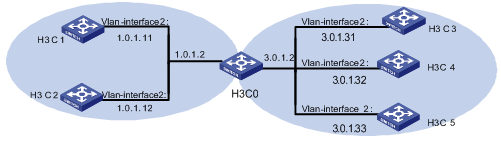
Figure 1-3 Network diagram for NTP configuration
III. Configuration procedure
Configure Switch H3C 3.
# Enter system view.
<H3C3> system-view
# Set the local clock as the NTP master clock at stratum 2.
[H3C3] ntp-service refclock-master 2
Configure Switch H3C 4.
# Enter system view.
<H3C4> system-view
# Set H3C 1 as the NTP server at stratum 3 after synchronization.
[H3C4] ntp-service unicast-server 3.0.1.31
# Set H3C 5 as peer
[H3C4] ntp-service unicast-peer 3.0.1.33
Configure Switch H3C 5.(H3C 4 has been synchronized by H3C 3)
# Enter system view.
<H3C5> system-view
# Set the local clock as the NTP master clock at stratum 1.
[H3C5] ntp-service refclock-master 1
# After performing local synchronization, set H3C 4 as a peer.
[H3C5] ntp-service unicast-peer 3.0.1.32
The above examples configure H3C 4 and H3C 5 as peers and configure H3C 5 as in active peer mode and H3C 4 in passive peer mode. Since H3C 5 is at stratum 1 and H3C 4 is at stratum 3, synchronize H3C 4 by H3C 5.
After synchronization, H3C 4 status is shown as follows:
[H3C4] display ntp-service status
Clock status: synchronized
Clock stratum: 2
Reference clock ID: 3.0.1.31
Nominal frequency: 60.0002 Hz
Actual frequency: 60.0002 Hz
Clock precision: 2^17
Clock offset: -9.8258 ms
Root delay: 27.10 ms
Root dispersion: 49.29 ms
Peer dispersion: 10.94 ms
Reference time: 19:21:32.287 UTC Oct 24 2004(C5267F3C.49A61E0C)
By this time, H3C 4 has been synchronized by H3C 5 and it is at stratum 2, or higher than H3C 5 by 1.
Display the sessions of H3C 4 and you will see H3C 4 has been connected with H3C 5.
[H3C4] display ntp-service sessions
source reference stra reach poll now offset delay disper
********************************************************************
[12345]3.0.1.33 LOCAL(0) 2 377 64 16 0.0 0.0 0.9
note: 1 source(master),2 source(peer),3 selected,4 candidate,5 configured
1.4.3 Configure NTP Broadcast Mode
I. Network requirements
On H3C 3, set local clock as the NTP master clock at stratum 2 and configure to broadcast packets from VLAN-interface 2. Configure H3C 4 and H3C 1 to listen to the broadcast from their VLAN-interface 2 respectively. (Note: H3C 3 supports to configure the local clock as the master clock)
II. Network diagram

Figure 1-4 Network diagram for NTP configuration
III. Configuration procedure
Configure Switch H3C 3:
# Enter system view.
<H3C3> system-view
# Set the local clock as the NTP master clock at stratum 2.
[H3C3] ntp-service refclock-master 2
# Enter VLAN-interface 2 view.
[H3C3] interface vlan-interface 2
# Set it as broadcast server.
[H3C3-Vlan-Interface2] ntp-service broadcast-server
Configure Switch H3C 4:
# Enter system view.
<H3C4> system-view
# Enter VLAN-interface 2 view.
[H3C4] interface vlan-interface 2
[H3C4-Vlan-Interface2] ntp-service broadcast-client
Configure Switch H3C 1:
# Enter system view.
<H3C1> system-view
# Enter VLAN-interface 2 view.
[H3C1] interface vlan-interface 2
[H3C1-Vlan-Interface2] ntp-service broadcast-client
The above examples configured H3C 4 and H3C 1 to listen to the broadcast through VLAN-interface 2, H3C 3 to broadcast packets from VLAN-interface 2. Since H3C 1 and H3C 3 are not located on the same segment, they cannot receive any broadcast packets from H3C 3, while H3C 4 is synchronized by H3C 3 after receiving its broadcast packet.
After the synchronization, you can find the state of H3C 4 as follows:
[H3C4] display ntp-service status
clock status: synchronized
clock stratum: 3
reference clock ID: LOCAL(0)
nominal frequency: 100.0000 Hz
actual frequency: 100.0000 Hz
clock precision: 2^17
clock offset: 0.0000 ms
root delay: 0.00 ms
root dispersion: 10.94 ms
peer dispersion: 10.00 ms
reference time: 20:54:25.156 UTC Mar 7 2002(C0325201.2811A112)
By this time, H3C 4 has been synchronized by H3C 3 and it is at stratum 3, higher than H3C 3 by 1.
Display the status of H3C 4 sessions and you will see H3C 4 has been connected to H3C 3.
[H3C4] display ntp-service sessions
source reference stra reach poll now offset delay disper
********************************************************************************
[1234]3.0.1.31 127.127.1.0 2 1 64 - 0.0 38.1 0.1
note: 1 source(master),2 source(peer),3 selected,4 candidate,5 configured
1.4.4 Configure NTP Multicast Mode
I. Network requirements
H3C 3 sets the local clock as the master clock at stratum 2 and multicast packets from VLAN-interface 2. Set H3C 4 and H3C 1 to receive multicast messages from their respective VLAN-interface 2. (Note: H3C 3 supports to configure the local clock as the master clock)
II. Network diagram
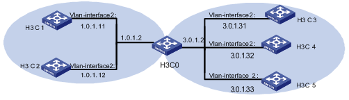
Figure 1-5 Network diagram for NTP configuration example
III. Configuration procedure
Configure Switch H3C 3:
# Enter system view.
<H3C3> system-view
# Set the local clock as a master NTP clock at stratum 2.
[H3C3] ntp-service refclock-master 2
# Enter VLAN-interface 2 view.
[H3C3] interface vlan-interface 2
# Set it as a multicast server.
[H3C3-Vlan-Interface2] ntp-service multicast-server
Configure Switch H3C 4:
# Enter system view.
<H3C4> system-view
# Enter VLAN-interface 2 view.
[H3C4] interface vlan-interface 2
# Enable multicast client mode.
[H3C4-Vlan-Interface2] ntp-service multicast-client
Configure Switch H3C 1:
# Enter system view.
<H3C1> system-view
# Enter VLAN-interface 2 view.
[H3C1] interface vlan-interface 2
# Enable multicast client mode.
[H3C1-Vlan-Interface2] ntp-service multicast-client
The above examples configure H3C 4 and H3C 1 to receive multicast messages from VLAN-interface2, H3C 3 multicast messages from VLAN-interface2. Since H3C 1 and H3C 3 are not located on the same segments, H3C 1 cannot receive the multicast packets from H3C 3, while H3C 4 is synchronized by H3C 3 after receiving the multicast packet.
1.4.5 Configure Authentication-Enabled NTP Server Mode
I. Network requirements
H3C 1 sets the local clock as the NTP master clock at stratum 2. H3C 2 sets H3C 1 as its time server in Server mode and itself in Client mode and enables authentication. (Note: H3C 1 supports to configure the local clock as the master clock)
II. Network diagram
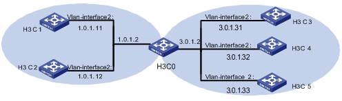
Figure 1-6 Network diagram for NTP configuration example
III. Configuration procedure
Configure Switch H3C 1.
# Enter system view.
<H3C1> system-view
# Set the local clock as the master NTP clock at stratum 2.
[H3C1] ntp-service refclcok-master 2
Configure Switch H3C 2.
# Enter system view.
<H3C2> system-view
# Set H3C 1 as time server.
[H3C2 [ntp-service unicast-server 1.0.1.11
# Enable authentication.
[H3C2] ntp-service authentication enable
# Set the key.
[H3C2] ntp-service authentication-keyid 42 authentication-mode md5 aNiceKey
# Set the key as reliable.
[H3C2] ntp-service reliable authentication-keyid 42
[H3C2] ntp-service unicast-server 1.0.1.11 authentication-keyid 42
The above examples synchronized H3C 2 by H3C 1. Since H3C 1 has not been enabled authentication, it cannot synchronize H3C 2. And now let us do the following additional configurations on H3C 1.
# Enable authentication.
[H3C1] ntp-service authentication enable
# Set the key.
[H3C1] ntp-service authentication-keyid 42 authentication-mode md5 aNiceKey
# Configure the key as reliable.
[H3C1] ntp-service reliable authentication-keyid 42