- Table of Contents
-
- H3C S9500 Operation Manual-Release1648[v1.24]-08 System Volume
- 00-1Cover
- 01-Command Line Interface Configuration
- 02-Login and User Interface Configuration
- 03-FTP and TFTP Configuration
- 04-HA Configuration
- 05-NQA Configuration
- 06-NetStream Configuration
- 07-NTP Configuration
- 08-RMON Configuration
- 09-SNMP Configuration
- 10-Packet Statistics Accounting Configuration
- 11-Device Management Configuration
- 12-Configuration File Management Configuration
- 13-File System Management Configuration
- 14-Cluster Management Configuration
- 15-System Maintenance and Debugging Configuration
- 16-Information Center Configuration
- 17-PoE Configuration
- 18-Clock Module Configuration
- 19-ACSEI Server Configuration
- 20-OAP Module Configuration
- Related Documents
-
| Title | Size | Download |
|---|---|---|
| 18-Clock Module Configuration | 86.09 KB |
Chapter 1 Configuring Clock Module
1.1 Introduction to Clock Module
1.4 Clock Module Configuration Example
Chapter 1 Configuring Clock Module
When configuring clock module, go to these sections for information you are interested in:
l Introduction to Clock Module
l Clock Module Configuration Example
1.1 Introduction to Clock Module
The clock module is responsible for providing high-precision and high-reliability synchronous 38.88 MHz SDH clock signals for all LPUs. The clock module selects an input clock source automatically, performs software phase-lock function, and monitors the board status in real time. As a branch of system operation management module on the SRPU, the clock module is responsible for passing the clock commands sent out by the network management system and the command line to the clock board of the SRPU, and for processing the responses from the clock board, as well as the messages reported by the clock board.
The clock module supports the hard reset of the clock board, and supports 18 clock sources. Every clock source matches a corresponding slot, dependent on the hardware configuration. The following figure shows the matching relationship between the clock source and the slot of the S9500 series switches:
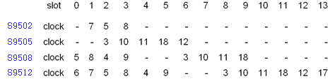
Figure 1-1 Mapping between the line clock source and the slot
1.2 Configuring Clock Module
Follow these steps to configure clock module:
|
To do… |
Use the command… |
Remarks |
|
Enter system view |
system-view |
— |
|
Set the working mode of the clock module on the SRPU |
clock { auto | manual source source-no } |
Optional By default, the working mode of the clock module on the SRPU is auto mode. |
|
Set the priority of the reference source |
clock priority value source source-no |
Optional 255 by default |
|
Set the SSM level |
clock ssm { dnu | lnc | prc | sets | tnc | unknown } source source-no |
Optional By default, the SSM level of all clock sources is unknown. |
|
Set the time slot of Bits clock source |
clock sa-bit { sa4 | sa5 | sa6 | sa7 | sa8 } source source-no |
Optional By default, the time slot of Bits clock source is sa4. |
|
Set SSM extraction flag |
clock forcessm { on | off } source source-no |
Optional |
|
Force the clock module to stop warming up the local oscillator |
clock stop warm-up |
Optional |
|
Set SSM to participate in control |
clock ssmcontrol { on | off } |
Optional By default, the SSM function of the clock does not participate in control. |
|
Set the output port of the line clock source |
clock lpuport slot slotid card cardid port portid |
Optional |
1.3 Displaying Clock Module
|
To do… |
Use the command… |
Remarks |
|
Display detailed information on clock device |
display clock device |
Available in any view |
|
Display version information of clock device |
display clock version |
Available in any view |
|
Display D/A value of clock device |
display clock d/a |
Available in any view |
|
Display base phase of clock device |
display clock basephase |
Available in any view |
|
Display output port of clock source on LPU |
display clock lpuport |
Available in any view |
|
Display the status of 18 clock sources |
display clock source |
Available in any view |
|
Display the self test result of clock |
display clock self-test-result |
Available in any view |
|
Display the priorities of 18 clock sources |
display clock priority |
Available in any view |
|
Display SSM levels of 18 clock sources |
display clock ssm-level |
Available in any view |
|
Display SSM output level of clock |
display clock ssm-output |
Available in any view |
|
Display phase lock status of clock |
display clock phase-lock-state |
Available in any view |
|
Display clock working mode |
display clock work-mode |
Available in any view |
|
Display current configuration of clock module |
display clock config |
Available in any view |
1.4 Clock Module Configuration Example
I. Network requirements
l Two S9508 switches Switch A and Switch B are connected by POS interfaces. Switch A equipped with clock monitoring module on its SRPU, but Switch B not.
l The synchronized clock of Switch A is provided by the clock monitoring module on its SRPU.
l Switch B adopts the line clock from Switch A to synchronize with the SDH line of Switch A.
II. Network diagram
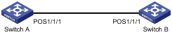
Figure 1-2 Diagram for the system clock configuration
III. Configuration procedure
l Configurations on the Switch A (configure the master clock).
# Set the interface POS 1/1/1 to work in master clock mode, using local clock signals.
<Sysname> system-view
[Sysname] interface pos 1/1/1
[Sysname-Pos1/1/1] clock master
l Configurations on the Switch B (configure the slave clock).
# Set the line clock source input interface on Switch B to POS 1/1/1.
<Sysname> system-view
[Sysname] clock lpuport pos 1/1/1
# Set the interface POS 1/1/1 to work in slave clock mode.
[Sysname] interface pos 1/1/1
[Sysname-Pos1/1/1] clock slave
# Enable the clock source from POS 1/1/1; set the clock to work in manual mode and adopt clock source 8, which corresponds to slot 1 (refer to Figure 1-1).
[Sysname] clock manual source 8
Through the above configurations, all the other POS interface cards get the same clock frequency derived by the clock monitoring module from the port 1 line clock of the POS interface card in slot 1. In this way, all the service cards on the device can get precise, reliable, synchronized SDH line interface clock signals.
