- Table of Contents
-
- H3C S9500 Operation Manual-Release1648[v1.24]-08 System Volume
- 00-1Cover
- 01-Command Line Interface Configuration
- 02-Login and User Interface Configuration
- 03-FTP and TFTP Configuration
- 04-HA Configuration
- 05-NQA Configuration
- 06-NetStream Configuration
- 07-NTP Configuration
- 08-RMON Configuration
- 09-SNMP Configuration
- 10-Packet Statistics Accounting Configuration
- 11-Device Management Configuration
- 12-Configuration File Management Configuration
- 13-File System Management Configuration
- 14-Cluster Management Configuration
- 15-System Maintenance and Debugging Configuration
- 16-Information Center Configuration
- 17-PoE Configuration
- 18-Clock Module Configuration
- 19-ACSEI Server Configuration
- 20-OAP Module Configuration
- Related Documents
-
| Title | Size | Download |
|---|---|---|
| 11-Device Management Configuration | 70.99 KB |
Table of Contents
1.1 Device Management Overview
1.2 Device Management Configuration
1.2.2 Enabling the Timing Reboot Function
1.2.3 Specifying the Bootstrap Programs for the Switch
1.2.5 Setting Slot Temperature Limit
1.3 Displaying and Debugging Device Management
1.4 Device Management Configuration Example
1.4.1 Using the Switch as an FTP Client to Implement the Remote Upgrade
1.4.2 Using the Switch as an FTP Server to Implement the Remote Upgrade
Chapter 1 Device Management
When configuring device management, go to these sections for information you are interested in:
l Device Management Configuration
l Displaying and Debugging Device Management
l Device Management Configuration Example
1.1 Device Management Overview
With the device management function, the switch can display the current running state and event debugging information about the slots, thereby implementing the maintenance and management of the state and communication of the physical devices. In addition, there is a command available for rebooting the system, when some function failure occurs.
1.2 Device Management Configuration
The main device management tasks are to check the status of the boards, CPU, and the memory usage of the switch.
The following sections describe the configuration tasks for device management:
l Enabling the Timing Reboot Function
l Specifying the Bootstrap Programs for the Switch
l Setting Slot Temperature Limit
1.2.1 Rebooting the Switch
It would be necessary for users to reboot the switch when failure occurs.
Perform the following configuration in user view.
|
To do… |
Use the command… |
|
Root the switch |
reboot [ slot slot-no ] |
1.2.2 Enabling the Timing Reboot Function
After you enable the timing reboot function on the switch, the switch will be rebooted on the specified time.
Perform the following configuration in user view, and display schedule reboot command can be performed in any view.
|
To do… |
Use the command… |
|
Enable the timing reboot function of the switch, and set specified time and date |
schedule reboot at hh:mm [ yyyy/mm/dd ] |
|
Enable the timing reboot function of the switch, and set waiting time |
schedule reboot delay { hhh:mm | mmm } |
|
Cancel the parameter configuration of timing reboot function of the switch |
undo schedule reboot |
|
Check the parameter configuration of the reboot terminal service of the current switch |
display schedule reboot |
& Note:
l The precision of the rebooting timer is 1 minute. When you configure the timing reboot function, the system prompts a waiting time. The device will be rebooted within one minute at the expiry of the waiting time.
l If you are performing file operations when the device is to be rebooted, the system does not execute the command for the sake of security.
1.2.3 Specifying the Bootstrap Programs for the Switch
You can specify two bootstrap programs for both active and standby SRPUs of the switch, with one used as the primary program and the other as the backup program.
Follow the step below to specify a bootstrap program for the switch:
|
To do… |
Use the command… |
Remarks |
|
Specify the bootstrap program for the switch |
boot boot-loader { primary | backup } file-url [ slot slot-number ] |
Available in user view |
If the switch fails to boot up through the specified bootstrap program, it retries to boot up by using a program in the flash memory or the CF card. If it fails again, the switch fails to start.
The switch selects one application program as a bootstrap program from Flash or CF card according to different values of flag BootDev. The detail is as follows:
l There are two primary bootstrap programs: one is in the Flash card (assume it is A); the other is in the CF card (assume it is B).
l There are two backup programs too: one is in the Flash card (assume it is C); the other is in the CF card (assume it is D).
l There is one flag BootDev.
You can view or modify the names of the bootstrap programs and enable equipment flag BootDev.
The detailed rules that the switch follows in selecting a bootstrap program are as follows in Table 1-1.
Table 1-1 The sequence of bootstrap program selection by the switch
|
BootDev Value of for boot from primary bootstrap program |
BootDev value for boot from backup bootstrap program |
Bootstrap program selection sequence |
|
0 |
0 |
A, C, B, D |
|
0 |
1 |
A, D, B, C |
|
1 |
1 |
B, D, A, C |
|
1 |
0 |
B, C, A, D |
& Note:
l The H3C S9500 series switches (hereinafter referred to as S9500 series) support active/standby SRPU switchover. Both the active and standby SRPUs have a program system. The program user can operate the programs on both SRPUs. When you specify the bootstrap APP program for use by the standby SRPU at the next startup, make sure that the URL of the program starts with “slot[No.]#[flash: | cf:]/”, where [No.] is the slot number of the standby SRPU, and [flash: | cf:] is the name of the equipment, which can be a flash card of CR card. For example, if the standby SRPU is on slot 1, the URL of 9500.app program on the standby SRPU is “slot1#flash:/9500.app”.
l You must configure the boot file in the CF card or the root directory of the Flash memory. Otherwise, your configuration will be failed.
1.2.4 Upgrading Boot ROM
You can use followed command to upgrade the Boot ROM with the Boot ROM program in the Flash Memory. This configuration task facilitates the remote upgrade. You can upload the Boot ROM program file from a remote end to the switch by FTP and then use this command to upgrade the Boot ROM.
Perform the following configuration in user view.
|
To do… |
Use the command… |
|
Upgrade BootROM |
boot bootrom file-url slot slot-num-list |
& Note:
l During Boot ROM upgrade process, do not power off or reboot the switch or the card being upgraded.
l You can use the boot bootrom command to upgrade the Boot ROM of an SRPU (active or standby) with the file on the SRPU only.
l You cannot use the boot bootrom command to upgrade the Boot ROM of the SRPU and that of the interface card simultaneously.
1.2.5 Setting Slot Temperature Limit
The switch system alarms when the temperature on a slot exceeds the preset limit.
Perform the following configuration in user view.
|
To do… |
Use the command |
|
Set slot temperature limit |
temperature-limit slot-no down-value up-value |
|
Restore temperature limit to default value |
undo temperature-limit slot-no |
1.2.6 Updating LPUs
The size of the flash for an SRPU in an S9500 series routing switch is 16 MB, while the size of current host software including the host applications of the line processor unit (LPU) reaches over 15 MB. If a compact flash (CF) card is not added, the current flash cannot provide enough room to save loading files. Therefore for S9500 series routing switches (whose SRPU is with a 16 MB flash), the LPU cannot be updated according to the original procedure. To update it, you need to execute the following command to download the APP file containing the LPU host application to the system’s synchronous dynamic random access memory (SDRAM).
& Note:
If you use a CF card or the flash room of a subsequent SRPU expands to 64 MB, you need not to change the method to update cards. When loading files you only need to choose the APP files containing the application file of LPUs to update common interface cards and LPUs.
Perform the following configuration in system view.
|
To do… |
Use the command… |
|
Download the host applications of LPUs to the system memory |
update l3plus slot slot-no filename file-name ftpserver server-name username user-name password password [ port port-num ] |
![]() Caution:
Caution:
l When you use the update l3plus command to update LPUs, you must use the switch host APP file which includes the load program of L3PLUS LPUs.
l The maximum size of L3PLUS update file loaded by the update l3plus command is 24 M.
1.3 Displaying and Debugging Device Management
|
To do… |
Use the command… |
Remarks |
|
Display the module types and running states of each card |
display device [ detail | [ shelf shelf-no ] [ frame frame-no ] [ slot slot-no ] ] |
Available in any view |
|
Display the application deployed on next startup |
display boot-loader |
Available in any view |
|
Display the running state of the built-in fans |
display fan [ fan-id ] |
Available in any view |
|
Display the status of switch memory use |
display memory [ slot slot-no ] |
Available in any view |
|
Display the state of the power |
display power [ power-id ] |
Available in any view |
|
Display CPU occupancy |
display cpu [slot slot-no ] |
Available in any view |
1.4 Device Management Configuration Example
1.4.1 Using the Switch as an FTP Client to Implement the Remote Upgrade
I. Network requirements
The user logs in to the switch using Telnet, downloads the application from the FTP server to the flash memory of the switch, and implements remote upgrade using the right commands.
The switch serves as an FTP client and the remote PC as an FTP server. The configuration on the FTP server is as follows: an FTP user is configured with the name “switch”, the password “hello” and the read & write authority over the Switch root directory on the PC. The IP address of a VLAN interface on the switch is 1.1.1.1, and the IP address of the PC is 2.2.2.2. The switch and PC are reachable with each other.
The switch applications switch.app and boot.app are stored on the PC. Using FTP, these files can be downloaded from the remote FTP server to the switch.
II. Network diagram
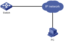
Figure 1-1 Network diagram for FTP configuration
III. Configuration procedure
1) Configure FTP server parameters on the PC: a user named as switch, password hello, read & write authority over the Switch directory on the PC. No further details are provided here
2) Configure the switch
# The switch has been configured with a Telnet user named as user, as 3-level user, with password hello, requiring username and password authentication.
# Use the telnet command to log into the switch.
![]() Caution:
Caution:
If the Flash Memory of the switch is not enough, you need to first delete the existing programs in the flash memory and then download the new ones to the memory.
# Enter the corresponding command in user view to establish FTP connection. Then enter correct username and password to log into the FTP server.
<H3C> ftp 2.2.2.2
Trying ...
Press CTRL+K to abort
Connected.
220 WFTPD 2.0 service (by Texas Imperial Software) ready for new user
User(none):switch
331 Give me your password, please
Password:*****
230 Logged in successfully
[ftp]
# Use the get command to download the switch.app and boot.app files from the FTP server to the flash directory on the FTP client.
[ftp] get switch.app
[ftp] get boot.app
# Use the quit command to release FTP connection and return to user view.
[ftp] quit
<H3C>
# Upgrade the Boot ROM of SRPU 0.
<H3C> boot bootrom boot.app slot 0
# Use the boot boot-loader command to specify the downloaded program as the application at the next login and reboot the switch.
<H3C> boot boot-loader primary flash:/switch.app slot 0
<H3C> display boot-loader
The primary app to boot of board 0 at the next time is: flash:/switch.app
The backup app to boot of board 0 at the next time is: flash:/switch.app
The app to boot of board 0 at this time is: flash:/switch.app
<H3C>
1.4.2 Using the Switch as an FTP Server to Implement the Remote Upgrade
I. Network requirements
The switch serves as an FTP server and the PC as an FTP client. The configuration on the FTP server is as follows: an FTP user is configured with the name “switch”, the password “hello” and the read & write authority over the root directory of the switch. The IP address of a VLAN interface on the switch is 1.1.1.1, and the IP address of the PC is 2.2.2.2. The switch and PC are reachable with each other.
The switch application switch.app is stored on the PC. Using FTP, this file can be uploaded from the PC to the switch remotely, and the configuration file switch20080101.cfg on the switch can be downloaded to the PC as a backup.
II. Network diagram
Figure 1-2 Network diagram for FTP configuration
III. Configuration procedure
1) Configure the switch
# Log in to the switch
Log in to the switch through the console port locally or through telnet remotely (refer to Login and User Interface Configuration of this manual for details about the login modes).
# Enable FTP on the switch; configure a username, password and path.
<H3C> system-view
[H3C] ftp server enable
[H3C] local-user switch
[H3C-luser-switch] service-type ftp ftp-directory flash:
[H3C-luser-switch] password simple hello
2) Run the FTP client program on the PC to set up an FTP connection with the switch. Then upload the switch program switch.app to the flash root directory on the switch and download the configuration file switch20080101.cfg from the switch. The FTP client program is not provided along with the switch, so, it is for you to purchase and install it.
![]() Caution:
Caution:
If the Flash Memory on the switch is not sufficient, delete the original application program in the flash before uploading the new one into the flash of the switch.
3) After uploading, performs upgrading on the switch.
<H3C>
# You can use the boot boot-loader command to specify the new file as the application program on the next booting and reboot the switch to implement the upgrading of the application program.
<H3C> boot boot-loader primary flash:/switch.app slot 0
<H3C> reboot
